RU2736607C2 - Valve drive unit with shape memory alloy actuator - Google Patents
Valve drive unit with shape memory alloy actuator Download PDFInfo
- Publication number
- RU2736607C2 RU2736607C2 RU2018146114A RU2018146114A RU2736607C2 RU 2736607 C2 RU2736607 C2 RU 2736607C2 RU 2018146114 A RU2018146114 A RU 2018146114A RU 2018146114 A RU2018146114 A RU 2018146114A RU 2736607 C2 RU2736607 C2 RU 2736607C2
- Authority
- RU
- Russia
- Prior art keywords
- valve
- sma
- drive
- pump
- sma wire
- Prior art date
Links
Images
Classifications
-
- A—HUMAN NECESSITIES
- A61—MEDICAL OR VETERINARY SCIENCE; HYGIENE
- A61M—DEVICES FOR INTRODUCING MEDIA INTO, OR ONTO, THE BODY; DEVICES FOR TRANSDUCING BODY MEDIA OR FOR TAKING MEDIA FROM THE BODY; DEVICES FOR PRODUCING OR ENDING SLEEP OR STUPOR
- A61M5/00—Devices for bringing media into the body in a subcutaneous, intra-vascular or intramuscular way; Accessories therefor, e.g. filling or cleaning devices, arm-rests
- A61M5/14—Infusion devices, e.g. infusing by gravity; Blood infusion; Accessories therefor
- A61M5/168—Means for controlling media flow to the body or for metering media to the body, e.g. drip meters, counters ; Monitoring media flow to the body
- A61M5/16804—Flow controllers
- A61M5/16813—Flow controllers by controlling the degree of opening of the flow line
-
- A—HUMAN NECESSITIES
- A61—MEDICAL OR VETERINARY SCIENCE; HYGIENE
- A61M—DEVICES FOR INTRODUCING MEDIA INTO, OR ONTO, THE BODY; DEVICES FOR TRANSDUCING BODY MEDIA OR FOR TAKING MEDIA FROM THE BODY; DEVICES FOR PRODUCING OR ENDING SLEEP OR STUPOR
- A61M5/00—Devices for bringing media into the body in a subcutaneous, intra-vascular or intramuscular way; Accessories therefor, e.g. filling or cleaning devices, arm-rests
- A61M5/14—Infusion devices, e.g. infusing by gravity; Blood infusion; Accessories therefor
- A61M5/142—Pressure infusion, e.g. using pumps
- A61M5/14244—Pressure infusion, e.g. using pumps adapted to be carried by the patient, e.g. portable on the body
- A61M5/14248—Pressure infusion, e.g. using pumps adapted to be carried by the patient, e.g. portable on the body of the skin patch type
-
- A—HUMAN NECESSITIES
- A61—MEDICAL OR VETERINARY SCIENCE; HYGIENE
- A61M—DEVICES FOR INTRODUCING MEDIA INTO, OR ONTO, THE BODY; DEVICES FOR TRANSDUCING BODY MEDIA OR FOR TAKING MEDIA FROM THE BODY; DEVICES FOR PRODUCING OR ENDING SLEEP OR STUPOR
- A61M5/00—Devices for bringing media into the body in a subcutaneous, intra-vascular or intramuscular way; Accessories therefor, e.g. filling or cleaning devices, arm-rests
- A61M5/14—Infusion devices, e.g. infusing by gravity; Blood infusion; Accessories therefor
- A61M5/142—Pressure infusion, e.g. using pumps
- A61M5/145—Pressure infusion, e.g. using pumps using pressurised reservoirs, e.g. pressurised by means of pistons
- A61M5/1452—Pressure infusion, e.g. using pumps using pressurised reservoirs, e.g. pressurised by means of pistons pressurised by means of pistons
-
- F—MECHANICAL ENGINEERING; LIGHTING; HEATING; WEAPONS; BLASTING
- F16—ENGINEERING ELEMENTS AND UNITS; GENERAL MEASURES FOR PRODUCING AND MAINTAINING EFFECTIVE FUNCTIONING OF MACHINES OR INSTALLATIONS; THERMAL INSULATION IN GENERAL
- F16K—VALVES; TAPS; COCKS; ACTUATING-FLOATS; DEVICES FOR VENTING OR AERATING
- F16K1/00—Lift valves or globe valves, i.e. cut-off apparatus with closure members having at least a component of their opening and closing motion perpendicular to the closing faces
- F16K1/16—Lift valves or globe valves, i.e. cut-off apparatus with closure members having at least a component of their opening and closing motion perpendicular to the closing faces with pivoted closure-members
- F16K1/18—Lift valves or globe valves, i.e. cut-off apparatus with closure members having at least a component of their opening and closing motion perpendicular to the closing faces with pivoted closure-members with pivoted discs or flaps
- F16K1/22—Lift valves or globe valves, i.e. cut-off apparatus with closure members having at least a component of their opening and closing motion perpendicular to the closing faces with pivoted closure-members with pivoted discs or flaps with axis of rotation crossing the valve member, e.g. butterfly valves
- F16K1/221—Lift valves or globe valves, i.e. cut-off apparatus with closure members having at least a component of their opening and closing motion perpendicular to the closing faces with pivoted closure-members with pivoted discs or flaps with axis of rotation crossing the valve member, e.g. butterfly valves specially adapted operating means therefor
-
- F—MECHANICAL ENGINEERING; LIGHTING; HEATING; WEAPONS; BLASTING
- F16—ENGINEERING ELEMENTS AND UNITS; GENERAL MEASURES FOR PRODUCING AND MAINTAINING EFFECTIVE FUNCTIONING OF MACHINES OR INSTALLATIONS; THERMAL INSULATION IN GENERAL
- F16K—VALVES; TAPS; COCKS; ACTUATING-FLOATS; DEVICES FOR VENTING OR AERATING
- F16K31/00—Actuating devices; Operating means; Releasing devices
- F16K31/02—Actuating devices; Operating means; Releasing devices electric; magnetic
- F16K31/025—Actuating devices; Operating means; Releasing devices electric; magnetic actuated by thermo-electric means
-
- A—HUMAN NECESSITIES
- A61—MEDICAL OR VETERINARY SCIENCE; HYGIENE
- A61M—DEVICES FOR INTRODUCING MEDIA INTO, OR ONTO, THE BODY; DEVICES FOR TRANSDUCING BODY MEDIA OR FOR TAKING MEDIA FROM THE BODY; DEVICES FOR PRODUCING OR ENDING SLEEP OR STUPOR
- A61M2205/00—General characteristics of the apparatus
- A61M2205/02—General characteristics of the apparatus characterised by a particular materials
- A61M2205/0266—Shape memory materials
-
- A—HUMAN NECESSITIES
- A61—MEDICAL OR VETERINARY SCIENCE; HYGIENE
- A61M—DEVICES FOR INTRODUCING MEDIA INTO, OR ONTO, THE BODY; DEVICES FOR TRANSDUCING BODY MEDIA OR FOR TAKING MEDIA FROM THE BODY; DEVICES FOR PRODUCING OR ENDING SLEEP OR STUPOR
- A61M2205/00—General characteristics of the apparatus
- A61M2205/33—Controlling, regulating or measuring
- A61M2205/3327—Measuring
Abstract
Description
Область техники, к которой относится настоящее изобретениеThe technical field to which the present invention relates
Настоящее раскрытие относится к области амбулаторных инфузионных насосов. Конкретно, оно относится к блокам привода для таких устройств, а также к дозирующим устройствам. Амбулаторные инфузионные насосы предназначены для инфузии жидкого лекарственного средства в организм пациента в течение продолжительного периода времени, и пациент носит их по существу непрерывно.The present disclosure relates to the field of ambulatory infusion pumps. More specifically, it relates to drive units for such devices as well as metering devices. Ambulatory infusion pumps are designed to infuse a liquid drug into a patient over an extended period of time and the patient wears them substantially continuously.
Предшествующий уровень техники настоящего изобретенияPrior art of the present invention
Амбулаторные инфузионные насосы хорошо известны в данной области, например, при лечении сахарного диабета путем постоянной подкожной инфузии инсулина (csii), а также при лечении боли или лечении рака, и поставляются рядом поставщиков.Ambulatory infusion pumps are well known in the art, for example, in the treatment of diabetes mellitus by continuous subcutaneous insulin infusion (csii), as well as in the treatment of pain or cancer treatment, and are available from a number of suppliers.
Согласно классической и общепринятой конструкции, такие амбулаторные инфузионные насосы или системы обычно относятся к типу шприцевых инфузионных насосов. В данной области известен ряд недостатков таких устройств. В частности, они имеют ограниченную точность, потому что они выполняют доставку очень маленьких количеств лекарственных средств, обычно в диапазоне нанолитров, непосредственно из картриджа для лекарственного средства в качестве основного резервуара для лекарственного средства, имеющего общий объем лекарственного средства в диапазоне миллилитров. Вследствие этого были предложены дополнительные концепции и архитектуры, в которых на выходе из основного резервуара для лекарственного средства используется выделенное дозирующее устройство, содержащее, например, микромембранный насос или микропоршень. Такие дозирующие устройства разработаны для точного дозирования малых объемов. Хотя в данной области известно несколько конструкций таких дозирующих устройств, они являются достаточно сложными. Большинство из них дорогие и/или рискованные с точки зрения крупномасштабного производства.According to the classic and conventional design, such ambulatory infusion pumps or systems are usually of the syringe infusion pump type. Several disadvantages of such devices are known in the art. In particular, they have limited accuracy because they deliver very small quantities of drugs, typically in the nanoliter range, directly from the drug cartridge as a primary drug reservoir having a total drug volume in the milliliter range. Consequently, additional concepts and architectures have been proposed that utilize a dedicated dispensing device at the outlet of the primary drug reservoir comprising, for example, a micromembrane pump or micropiston. These dispensers are designed to accurately dispense small volumes. Although several designs of such dispensing devices are known in the art, they are quite complex. Most of them are expensive and / or risky in terms of large scale production.
В ep1970677a1 раскрыта система с миниатюрным дозирующим поршневым насосом с дозирующим цилиндром, который многократно соединяют с большим основным резервуаром для лекарственного средства и наполняют из него с последующим соединением дозирующего цилиндра с местом инфузии и поэтапной инфузией жидкого лекарственного средства из дозирующего цилиндра обычно в диапазоне нанолитров или микролитров и в течение продолжительного периода времени, например, от нескольких часов до более чем суток, в зависимости от конкретных терапевтических потребностей пациента. Когда дозирующий цилиндр опорожняют, его снова наполняют из основного резервуара для лекарственного средства. После опорожнения основного резервуара для лекарственного средства и дозирующий насос, и основной резервуар для лекарственного средства можно выбросить и заменить. Альтернативно для соединения дозирующего цилиндра с резервуаром и местом инфузии предложена клапанная система. Настоящий документ основан на конструкции устройства инфузомата в соответствии с ep1970677a1.EP1970677a1 discloses a system with a miniature piston dosing pump with a dosing cylinder that is repeatedly connected to and refilled from a large primary drug reservoir, followed by connection of the dosing cylinder to the infusion site and staged infusion of the liquid drug from the dosing cylinder, usually in the nanoliter or microliter range and over an extended period of time, for example, from several hours to more than a day, depending on the particular therapeutic needs of the patient. When the dispensing cylinder is emptied, it is refilled from the main drug reservoir. After the main medication tank has been emptied, both the metering pump and the main medication tank can be discarded and replaced. Alternatively, a valve system is provided for connecting the dispensing cylinder to the reservoir and the infusion site. This document is based on the design of the infusion pump device in accordance with ep1970677a1.
Краткое раскрытие настоящего изобретенияSummary of the present invention
В ep2163273a1 раскрыто дозирующее устройство согласно принципам, установленным в ep1970677a1. Согласно ep2163273a1 дозирующее устройство соединено - обычно с возможностью отсоединения - с единственным блоком привода, который используют как для движения поршня, так и для переключения клапана в зависимости от положения поршня. Переключение клапана достигается за счет передвижения, например, вращения, дозирующего цилиндра дозирующего устройства относительно неподвижного элемента клапана, устанавливая таким образом поочередное жидкостное сообщение дозирующего цилиндра либо со впуском, либо с выпуском. Переключение клапана в частности не включает введение пациенту жидкости, которое достигается за счет перемещения поршня.Ep2163273a1 discloses a dispensing device according to the principles set out in ep1970677a1. According to ep2163273a1, the metering device is connected - usually detachably - to a single actuator block, which is used to both move the piston and switch the valve depending on the position of the piston. The switching of the valve is achieved by movement, for example, rotation, of the metering cylinder of the metering device relative to the stationary valve element, thus establishing alternate fluid communication of the metering cylinder with either the inlet or the outlet. Valve switching in particular does not include fluid delivery to the patient, which is achieved by piston movement.
В ep2881128a1 раскрыта в соответствии с ep1970677a1 конструкция, где переключение клапана и движение поршня выполняют посредством отдельных приводов с отдельными выделенными исполнительными механизмами, а не с общим исполнительным механизмом. Несмотря на то, что требуется некоторое дополнительное действие аппаратных средств, устранены критические вопросы разработки и упрощается общая структура управления.Ep2881128a1 discloses, in accordance with ep1970677a1, a design where valve switching and piston movement are performed by separate actuators with separate dedicated actuators rather than a common actuator. While some additional hardware action is required, critical design issues are eliminated and the overall control structure is simplified.
Поскольку дозирующее устройство обычно является одноразовым со значительно меньшим сроком службы по сравнению с устройствами привода и дополнительными функциональными блоками, такими как пользовательский интерфейс и контур управления, по соображениям затрат требуется модульная конструкция, где отдельно можно заменять дозирующее устройство. Для такой модульной конструкции, которая также предполагается в контексте настоящего раскрытия, требуется простое и отказоустойчивое соединение и отсоединение для неподготовленного в значительной степени пользователя, возможно со зрительными и/или двигательными нарушениями.Since the dispenser is typically disposable with a significantly shorter life span than drive devices and additional functional blocks such as user interface and control loop, for cost reasons a modular design is required where the dispenser can be separately replaced. Such a modular design, which is also contemplated in the context of the present disclosure, requires a simple and resilient connection and disconnection for a largely untrained user, possibly with visual and / or movement impairments.
Необходимо обеспечить безопасное и заданное соединение клапана, соответственно, поршня с соответствующим блоком привода клапана, соответственно, блоком привода насоса без необходимости нахождения задействованных интерфейсных систем в конкретном и четко заданном контрольном состоянии. В этом контексте в ep2881128a1 раскрыта конструкция, где клапан и блок привода клапана соединены посредством механизма ступенчатого переключения.It is necessary to ensure a safe and specified connection of the valve, respectively, the piston with the corresponding valve drive unit, respectively, the pump drive unit, without the need for the interface systems involved in a specific and well-defined control state. In this context, ep2881128a1 discloses a structure where the valve and the valve actuator are connected by a step change mechanism.
Общая цель настоящего изобретения состоит в улучшении состояния области техники, связанной с блоками привода и в частности с блоками привода клапанов для дозирующего устройства, как объяснялось ранее. Конкретная цель состоит в предоставлении блока привода клапана, который имеет компактную и жесткую конструкцию и который можно предпочтительно изготавливать экономичным способом.The general object of the present invention is to improve the state of the art related to drive units, and in particular to valve drive units for a metering device, as previously explained. A particular aim is to provide a valve drive unit that is compact and rigid in structure and which can be advantageously manufactured in an economical manner.
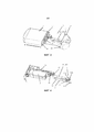
В общем смысле общая цель достигается посредством объектов независимых пунктов формулы изобретения. Иллюстративные и подходящие варианты осуществления определены в зависимой формуле изобретения и в общем раскрытии настоящего документа. Общая цель в частности достигается на основании использования в качестве исполнительных механизмов блока привода клапана с проводами sma (сплав с памятью формы). Провода sma воздействуют на поворотный элемент, который преобразует изменение длины (сокращая, соответственно, удлинение проводов sma) во вращательное движение, которое передается посредством интерфейсной системы в клапанный блок дозирующего устройства.In a general sense, the overall objective is achieved by the subjects of the independent claims. Illustrative and suitable embodiments are defined in the dependent claims and in the general disclosure of this document. The overall objective is particularly achieved through the use of an sma (shape memory alloy) valve drive unit as actuators. The sma wires act on a pivot element, which converts the change in length (thus reducing the elongation of the sma wires) into a rotary movement, which is transmitted via the interface system to the valve block of the metering device.
Использование исполнительных механизмов sma в контексте амбулаторных инфузионных насосов, например, инсулиновых помп, широко известно, например, из us20130197438a1, us7226278b2, us6656158b2, us20110319862a1, us20110009814a1 и w09938551a1. Согласно этим документам, исполнительный механизм sma используют непосредственно для дозирования лекарственного средства. В некоторых случаях дозирующий клапан открывают и закрывают посредством исполнительного механизма sma, при этом лекарственное средство вводят при условии открытого клапана.The use of sma actuators in the context of ambulatory infusion pumps, such as insulin pumps, is widely known, for example from us20130197438a1, us7226278b2, us6656158b2, us20110319862a1, us20110009814a1 and w09938551a1. According to these documents, the sma actuator is used directly for drug dispensing. In some cases, the metering valve is opened and closed by the sma actuator and the drug is administered under the condition that the valve is open.
В отличие от этого, согласно настоящему изобретению, исполнительный механизм sma используют для управления, соответственно, переключением клапана управления, который соединяет дозирующий цилиндр дозирующего устройства поочередно с пациентом, например, через инфузионную систему или с картриджем для лекарственного средства или вообще с основным резервуаром для лекарственного средства. Однако переключение клапана и, соответственно, приведение в действие исполнительного механизма sma само по себе не приводит к введению какого-либо лекарственного средства. Вместо этого введением лекарственного средства управляют посредством отдельного блока привода насоса, причем дозирующий цилиндр и поршень образуют объемный дозирующий насос в качестве признанной и проверенной конструкции.In contrast, according to the present invention, the sma actuator is used to control, respectively, the switching of the control valve, which connects the dosing cylinder of the dosing device alternately with the patient, for example, via an infusion system or with a cartridge for a medication or in general with a main reservoir for a medication. facilities. However, switching the valve and thus actuating the sma actuator does not in itself lead to the administration of any medication. Instead, drug delivery is controlled by a separate pump drive unit, with the metering cylinder and piston forming a positive displacement metering pump as a recognized and proven design.
В аспекте общая цель достигается посредством блока привода клапана. Блок привода клапана может быть выполнен специально для использования в качестве части блока привода и в сочетании с дозирующим устройством, как объяснено дополнительно ниже. Блок привода клапана содержит первый провод sma и второй провод sma, при этом первый и второй провод sma можно активировать поочередно.In an aspect, the overall objective is achieved by a valve actuator assembly. The valve drive unit can be designed specifically for use as part of the drive unit and in combination with a metering device, as explained further below. The valve actuator assembly contains a first sma wire and a second sma wire, whereby the first and second sma wires can be activated alternately.
Блок привода клапана дополнительно содержит поворотный элемент. Поворотный элемент выполнен с возможностью поворота вокруг оси поворотного элемента. Поворотный элемент содержит привод клапана. Привод клапана расположен на расстоянии от оси поворотного элемента.The valve drive unit additionally contains a rotary element. The rotary element is made with the possibility of rotation around the axis of the rotary element. The rotary element contains a valve drive. The valve drive is located at a distance from the axis of the rotary element.
Первый и второй провод sma соединены с поворотным элементом таким образом, что приведение в действие первого провода sma вызывает/обеспечивает поворот поворотного элемента в первом направлении, а приведение в действие второго провода sma вызывает/обеспечивает поворот поворотного элемента во втором направлении, причем второе направление противоположно первому направлению. Для соединения первого и второго проводов sma поворотный элемент содержит первую и вторую соединительную конструкцию sma.The first and second sma wires are connected to the pivot so that the actuation of the first sma wire causes / allows the pivot to rotate in the first direction, and the actuation of the second sma wire causes / allows the pivot to rotate in the second direction, the second direction being opposite the first direction. To connect the first and second sma wires, the pivot contains the first and second sma connecting structure.
Привод клапана выполнен с возможностью разъемного зацепления соединительного элемента привода клапана клапанного блока таким образом, что в зацепленном состоянии поворот поворотного элемента передается на соединительный элемент привода клапана через привод клапана. Как дополнительно объяснено более подробно ниже, разъемным зацеплением в частности может быть разъемное координирующее зацепление. Соединение между приводом клапана и соединительным элементом привода клапана таково, что функция передачи между приводом клапана и соединительным элементом привода клапана является непрерывной, т.е. непрерывное (поворачивающее) движение привода клапана приводит к соответствующему непрерывному движению соединительного элемента привода клапана в отличие от механизма ступенчатого переключения с разрывной функцией передачи.The valve drive is configured to detachably engage the valve drive connector of the valve unit so that in the engaged state the rotation of the rotary member is transmitted to the valve drive connector via the valve drive. As further explained in more detail below, the releasable engagement may in particular be a releasable coordinating engagement. The connection between the valve drive and the valve drive connection is such that the transfer function between the valve drive and the valve drive connection is continuous, i.e. the continuous (rotary) movement of the valve actuator results in a corresponding continuous movement of the valve actuator coupling, as opposed to a staggered mechanism with a burst transmission function.
Как будет дополнительно объяснено более подробно ниже, поворотный элемент преобразует прямолинейное движение, в частности укорачивание, соответственно, растяжение проводов sma в соответствующий поворот поворотного элемента. Поворотный элемент, соответственно, служит в качестве преобразующего элемента. Вследствие того, что привод клапана представляет собой неотъемлемую часть поворотного элемента, поворот поворотного элемента также приводит к повороту привода клапана вокруг оси поворотного элемента на (круговой) траектории, которая определяется расстоянием между осью поворотного элемента и приводом клапана.As will be further explained in more detail below, the pivot element converts the rectilinear movement, in particular the shortening or stretching of the sma wires, into a corresponding pivot element. The pivot element accordingly serves as a conversion element. Due to the fact that the valve actuator is an integral part of the rotary member, rotation of the rotary member also causes the valve actuator to rotate about the axis of the rotary member on a (circular) path that is determined by the distance between the axis of the rotary member and the valve actuator.
Провода sma обеспечивают генерирование большого (тянущего) усилия, когда они укорачиваются при нагревании (обычно за счет их электрического сопротивления, когда по проводу протекает ток возбуждения), но могут пассивно натягиваться или удлиняться за счет небольшого усилия ниже температуры активации/приведения в действие. Во многих вариантах применения недостаток исполнительных механизмов sma состоит в маленькой используемой длине хода при укорачивании, самое большее в диапазоне нескольких процентов длины провода. По этой причине использование исполнительных механизмов sma невозможно во многих вариантах применения, или для увеличения длины хода необходимо сложное механическое кинематическое устройство. В отличие от этого блок привода клапана в соответствии с настоящим раскрытием можно осуществить компактно и с небольшим количеством компонентов.Sma wires generate a large (pulling) force when they are shortened when heated (usually by their electrical resistance when field current flows through the wire), but can be passively pulled or lengthened by a small force below the activation / actuation temperature. In many applications, sma actuators have the disadvantage of a small usable shortening stroke, at most in the range of a few percent of the wire length. For this reason, the use of sma actuators is not possible in many applications, or a complex mechanical kinematic arrangement is required to increase the stroke length. In contrast, a valve actuator assembly according to the present disclosure can be implemented in a compact manner and with few components.
Каждый из первого и второго проводов sma укорачивается после предшествующего пассивного растяжения при активации посредством нагревания электрическим током провода sma, стремящегося вернуться к своей запомненной форме и длине. Во время работы ток подается в первый и второй провода sma таким образом, что в любой момент времени активирован только первый провод sma, только второй провод sma или ни один из первого и второго проводов sma, но не оба. С этой целью привод клапана может содержать соответствующий контур управления приводом клапана. В этом документе выражения «запомненная форма» и «запомненная длина» относятся к конструктивно заданной форме и длине, к которой провода sma стремятся вернуться при нагревании до температуры активации. Хотя и не важно, запомненная форма проводов sma обычно прямая или близкая к прямой.Each of the first and second sma wires is shortened after previous passive stretching when activated by electrical heating of the sma wire, tending to return to its memorized shape and length. During operation, current is supplied to the first and second sma wires in such a way that at any given time, only the first sma wire, only the second sma wire, or neither of the first and second sma wires but not both are activated. For this purpose, the valve actuator can comprise a corresponding valve actuator control loop. In this document, the expressions "shape memorized" and "memorized length" refer to the design-defined shape and length to which the sma wires tend to return when heated to the activation temperature. Although not important, the memorized shape of sma wires is usually straight or nearly straight.
В дополнение к поворотному элементу каждый из первого и второго проводов sma соединен с неподвижной опорной конструкцией и, соответственно, действует между поворотным элементом и опорной конструкцией.In addition to the pivot member, each of the first and second wires sma is connected to the stationary support structure, and accordingly acts between the pivot member and the support structure.
В контексте работы клапанного блока дозирующего устройства, как дополнительно обсуждается более подробно ниже, поворот поворотного элемента и привода клапана в первом направлении приводит к передвижению корпуса отключения клапанного блока в положение наполнения. Аналогично, поворот поворотного элемента и привода клапана во втором направлении приводит к передвижению корпуса отключения в положение опорожнения. Переключение между положением наполнения и положением опорожнения, соответственно, достигается посредством выборочного приведения в действие/активации первого, соответственно, второго провода sma. В варианте осуществления привод клапана представляет собой зацепляющий штифт.In the context of dispensing valve block operation, as discussed further in more detail below, rotation of the pivot member and valve actuator in the first direction moves the valve block shut-off body to the fill position. Likewise, pivoting the rotary member and valve actuator in the second direction moves the shut-off body to the empty position. Switching between the filling position and the emptying position, respectively, is achieved by selectively driving / activating the first or second sma wire. In an embodiment, the valve actuator is an engaging pin.
Первый и второй провод sma можно изготовить из любого подходящего материала sma, известного в данной области, в частности меди-алюминия-никеля или никеля-титана, но также можно изготовить путем получения сплава других материалов, таких как цинк, медь, золото и железо. Обычно первый и второй провод sma имеют идентичную конструкцию и размеры, что приводит к симметричной системе.The first and second sma wire can be made from any suitable sma material known in the art, such as copper-aluminum-nickel or nickel-titanium, but can also be made by alloying other materials such as zinc, copper, gold and iron. Usually, the first and second sma wires are identical in design and dimensions, resulting in a symmetrical system.
В варианте осуществления привод клапана сам по себе не содержит стопоров, которые ограничивали бы поворот поворотного элемента в конечном положении. Вместо этого поворот поворотного элемента во время работы ограничен стопорами клапанов клапанного блока. Аналогично, в обычных вариантах осуществления для удерживания поворотного элемента в заданном положении не нужны никакие захваты, запоры и тому подобное.In an embodiment, the valve actuator itself does not include stops that would restrict the rotation of the pivot member in the end position. Instead, rotation of the pivot during operation is limited by the valve block valve stoppers. Likewise, in conventional embodiments, no grips, locks or the like are needed to hold the pivot member in position.
В варианте осуществления устройство первого и второго проводов sma таково, что приведение в действие первого провода sma удлиняет второй провод sma, а приведение в действие второго провода sma удлиняет первый провод sma. В таком варианте осуществления один из первого и второго проводов sma в стационарной ситуации, когда не активирован ни один из проводов sma, находится в укороченном состоянии (с минимальной длиной), тогда как другой из первого и второго проводов sma находится в удлиненном или натянутом состоянии (с максимальной длиной). Во время работы состояние первого и второго проводов sma с каждым переключением клапана между положением впуска и положением опорожнения корпуса отключения изменяется на обратное. Такое устройство является предпочтительным, поскольку для удлинения проводов sma не нужны дополнительные противодействующие элементы, такие как пружины.In an embodiment, the arrangement of the first and second sma wires is such that driving the first sma wire lengthens the second sma wire and driving the second sma wire lengthens the first sma wire. In such an embodiment, one of the first and second sma wires in a stationary situation, when none of the sma wires is activated, is in a shortened state (with a minimum length), while the other of the first and second sma wires is in an extended or tense state ( with maximum length). During operation, the state of the first and second sma wires is reversed each time the valve switches between the inlet position and the empty position of the shut-off body. Such a device is preferred since no additional opposing elements such as springs are required to lengthen the sma wires.
В варианте осуществления поворотный элемент содержит первую соединительную конструкцию sma и вторую соединительную конструкцию sma. Первая соединительная конструкция sma соединена с первым проводом sma, а вторая соединительная конструкция sma соединена со вторым проводом sma. Первая, соответственно, вторая соединительные конструкции sma, кроме того, расположены на противоположных сторонах оси поворотного элемента.In an embodiment, the pivot member comprises a first connecting structure sma and a second connecting structure sma. The first sma connector is connected to the first sma wire and the second sma connector is connected to the second sma wire. The first or second connecting structures sma are also located on opposite sides of the axis of the pivot element.
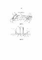
В варианте осуществления каждый из первого и второго провода sma является u-образным. В таком варианте осуществления основание u-образных проводов sma (область, где встречаются оба ответвления «u») соединено с поворотным элементом, тогда как свободные концы обоих ответвлений соединены с опорной конструкцией. Посредством первой и второй соединительной конструкции sma первый и второй провод sma, соответственно, отклоняют или складывают назад, например, на 180°. Обычно для каждого из первого и второго проводов sma оба ответвления параллельны. Кроме того, обычно параллельны ответвления обоих u-образных проводов sma. Кроме того, обычно u-форма является симметричной, причем оба ответвления имеют одинаковую длину.In an embodiment, each of the first and second sma wires is u-shaped. In such an embodiment, the base of the sma u-wires (the area where both “u” branches meet) are connected to the pivot member, while the free ends of both branches are connected to the support structure. By means of the first and second connecting structure sma, the first and second sma wires are respectively deflected or folded back, for example by 180 °. Usually, for each of the first and second sma wires, both taps are parallel. In addition, the taps of both sma u-wires are usually parallel. In addition, the u-shape is usually symmetrical, with both arms being the same length.
U-образная форма этого типа варианта осуществления приводит к «складыванию» первого и второго проводов sma пополам. Таким образом, общие усилия, которые прикладывают ответвления, суммируются, и общее тянущее усилие, соответственно, для u-образной конфигурации удваивается по сравнению с проводом sma, имеющим длину одного ответвления. Для данного требуемого общего усилия, соответственно, можно использовать более тонкие провода sma, причем электрическое сопротивление увеличивается с уменьшением диаметра. Кроме того, поскольку электрическое сопротивление зависит от общей длины проводов sma, электрическое сопротивление u-образной конфигурации, соответственно, имеет двойное электрическое сопротивление одного ответвления идентичного диаметра. Сложенная конструкция, соответственно, приводит к сравнительно высокому электрическому сопротивлению, которое подходит для того, чтобы ограничить требуемый ток для нагревания. В принципе, также возможно иное складывание, например, тройное складывание (которое приводит к «форме n») или четверное складывание (которое приводит к «форме m»). Однако такие конфигурации обычно являются менее предпочтительными с точки зрения общего требуемого пространства для установки и общих ограничений конструкции.The U-shape of this type of embodiment causes the first and second sma wires to "fold" in half. Thus, the total forces applied by the branches add up and the total pulling force, respectively, for the u-shaped configuration is doubled compared to the sma wire having one branch length. For a given required total force, accordingly, thinner sma wires can be used, the electrical resistance increasing with decreasing diameter. In addition, since the electrical resistance depends on the total length of the sma wires, the electrical resistance of the u-shaped configuration accordingly has twice the electrical resistance of one branch of the same diameter. The folded structure accordingly results in a relatively high electrical resistance which is suitable for limiting the required heating current. In principle, other folding is also possible, for example triple folding (which leads to "n-shape") or quadruple-folding (which leads to "m" shape). However, such configurations are generally less preferred in terms of overall installation space requirements and general design constraints.
Во всех этих конфигурациях, когда первый, соответственно, второй провод sma отклоняется или складывается поворотным элементом назад, поворотный элемент полностью или в области соединения с проводами sma предпочтительно сделан из металла, имеет металлическое покрытие или в общем является электропроводным. Преимущественный эффект этого состоит в том, что происходит электрическое короткое замыкание поворотным элементом значительно деформированной части проводов sma, когда они отклоняются, соответственно, складываются назад. Следовательно, по меньшей мере большая часть тока нагревания проходит не через эту часть проводов sma, но через поворотный элемент. Для u-образной конструкции проводов sma основное прохождение тока происходит, соответственно, из одного из ответвлений через поворотный элемент в другое ответвление, а не через основание u. Соответственно, деформированное основание в отличие от ответвлений не нагревается до температуры активации. Таким образом, механическая нагрузка на провода sma значительно уменьшается.In all of these configurations, when the first or second sma wire is tilted or folded back by the pivot element, the pivot element is preferably made entirely of or in the area of connection with the sma wires, made of metal, has a metal coating or is generally electrically conductive. The advantageous effect of this is that the pivot element will electrically short-circuit the significantly deformed part of the sma wires when they are deflected or folded back. Therefore, at least most of the heating current does not pass through this part of the sma wires, but through the pivot element. For the u-shaped design of sma wires, the main current flow, respectively, from one of the branches through the rotary element to the other branch, and not through the base u. Accordingly, the deformed base, in contrast to the branches, does not heat up to the activation temperature. Thus, the mechanical stress on the sma wires is significantly reduced.
В одном варианте два ответвления u-образного провода sma можно заменить на две отдельные части провода sma. Аналогично, конфигурацию с формой n или формой m можно заменить на три, соответственно, четыре отдельные части провода sma.In one embodiment, the two branches of the sma u-wire can be replaced with two separate sma wire pieces. Likewise, the shape n or shape m configuration can be replaced with three or four separate pieces of sma wire.
В варианте осуществления первый провод sma соединен с опорной конструкцией посредством первой пружинной конструкции, а второй провод sma соединен с опорной конструкцией посредством второй пружинной конструкции. Как будет объяснено более подробно далее соединение через пружинную конструкцию предпочтительно для предотвращения избыточной нагрузки и, соответственно, повреждения исполнительного механизма клапана, которое в противном случае может произойти в неблагоприятных обстоятельствах.In an embodiment, the first sma wire is connected to the support structure by the first spring structure and the second sma wire is connected to the support structure by the second spring structure. As will be explained in more detail below, the connection through the spring structure is preferable to prevent overloading and thus damage to the valve actuator, which could otherwise occur under unfavorable circumstances.
В варианте осуществления, где первый и второй провод sma являются u-образными, как объяснялось ранее, каждая из первой и второй пружинной конструкции может состоять из двух отдельных пружинных элемента, причем каждый пружинный элемент отдельно соединяет одно ответвление провода sma с опорной конструкцией. В одном примере пружинные элементы представляют собой листовые пружины, которые на конце прочно соединены с опорной конструкцией, например, посредством винтов или заклепок.In an embodiment where the first and second sma wires are u-shaped as previously explained, the first and second spring structures may each be composed of two separate spring members, each spring member separately connecting one branch of the sma wire to the support structure. In one example, the spring elements are leaf springs that are end-firmly connected to the support structure, for example by screws or rivets.
Обычно, первая и вторая пружинная конструкция, и в варианте осуществления с четырьмя пружинными элементами, как объяснялось ранее, все четыре пружинных элемента имеют идентичную конструкцию и размеры, что приводит к симметричной системе.Typically, the first and second spring structures, and in the four spring member embodiment, as previously explained, all four spring members are of identical design and dimensions, resulting in a symmetrical system.
В варианте осуществления первая пружинная конструкция выполнена с возможностью сохранения соединения между первым проводом sma и первой пружинной конструкции в постоянном положении для усилия, которое прикладывает первый провод sma, ниже первого порогового усилия. Также, вторая пружинная конструкция выполнена с возможностью сохранения соединения между вторым проводом sma и второй пружинной конструкцией в постоянном положении для усилия, которое прикладывает второй провод sma, ниже второго порогового усилия. За пределами тянущего усилия, которое прикладывает первый, соответственно, второй sma, превышающего первое, соответственно, второе пороговое усилие, первый, соответственно, второй пружинный элемент отклоняется. В обычном варианте осуществления первое и второе пороговое усилие выбирают идентичными.In an embodiment, the first spring structure is configured to keep the connection between the first sma wire and the first spring structure in a constant position for the force exerted by the first sma wire below the first threshold force. Also, the second spring structure is configured to keep the connection between the second sma wire and the second spring structure in a constant position for the force exerted by the second sma wire below the second threshold force. Outside of the pulling force exerted by the first or second sma exceeding the first or second threshold force, the first or second spring element is deflected. In a typical embodiment, the first and second threshold forces are selected to be identical.
В варианте осуществления первая пружинная конструкция ограничивает усилие, которое может прикладывать первый провод sma, а вторая пружинная конструкция ограничивает усилие, которое может прикладывать второй провод sma.In an embodiment, the first spring structure limits the force that the first sma wire can apply, and the second spring structure limits the force that the second sma wire can apply.
Должно быть понятно, что запомненная длина провода sma, которая соответствует запомненной форме, имеет производственные допуски. Также, требуемое укорачивание первого, соответственно, второго провода sma определяется рядом параметров, которые имеют допуски. Чтобы справиться с этой ситуацией запомненную длину проводов sma необходимо выбирать таким образом, чтобы она была меньше, чем минимальная длина, которую можно практически принять во время работы. В рабочем состоянии дальнейшее движение поворотного элемента блокируется, когда корпус отключения клапанного блока принимает какое-либо из своих конечных положений, т.е. положение наполнения, соответственно, положение опорожнения. Поскольку выше температуры активации провода sma кроме того стремятся, соответственно, принять свою запомненную длину, жесткое соединение проводов sma с опорной конструкцией приводит к резкому увеличению усилия, возможно даже в целом повреждая провод sma и блок привода клапана. Такую ситуацию избыточной нагрузки предотвращает соединение через пружинные конструкции в том, что соединение между проводами sma и пружинными конструкциями имеет возможность двигаться, если усилие превышает пороговое усилие.It should be understood that the memorized length of the sma wire that matches the memorized shape has manufacturing tolerances. Also, the required shortening of the first or second sma wire is determined by a number of parameters that have tolerances. To cope with this situation, the memorized length of sma wires must be selected so that it is less than the minimum length that can be practically accepted during operation. In working condition, further movement of the pivot element is blocked when the valve block shut-off body assumes any of its end positions, i.e. the filling position or the emptying position. Since, above the activation temperature, the sma wires also tend to accordingly assume their memorized length, rigidly connecting the sma wires to the support structure leads to a dramatic increase in force, possibly even damaging the sma wire and the valve drive assembly altogether. This overload situation is prevented by the connection via the spring structures in that the connection between the sma wires and the spring structures is able to move if the force exceeds the threshold force.
Ситуация избыточной нагрузки, в которой необходимо ограничивать усилие, в дополнение к обсуждавшейся ранее ситуации, когда дальнейшее движение блокируется, может произойти особенно в неблагоприятных окружающих условиях, в частности при высоких температурах, например, при температурах хранения, которые могут быть выше температуры активации проводов sma, что приводит к укорачиванию как первого, так и второго провода sma. Получающаяся в результате избыточная нагрузка может повредить весь привод клапана и вызвать, например, разрыв провода sma. В такой ситуации усилие предпочтительно ограничивает упругое соединение посредством пружинной конструкции.An overload situation in which it is necessary to limit the force, in addition to the previously discussed situation where further movement is blocked, can occur especially in unfavorable environments, in particular at high temperatures, for example, at storage temperatures that can be higher than the activation temperature of sma wires , which shortens both the first and second sma wires. The resulting overload can damage the entire valve actuator and cause, for example, a break in the sma wire. In such a situation, the force preferably limits the resilient connection by means of a spring structure.
Предпочтительно, для каждого пружинного элемента предоставлен неподвижный опорный элемент, и пружинные элементы выполнены с возможностью опоры на неподвижную опору и подъема с опорного элемента при отклонении. Опорные элементы могут быть частью или жестко прикреплены к опорной конструкции. В нейтральном состоянии каждый из пружинных элементов опирается на свой опорный элемент с заданным номинальным усилием контакта, которое соответствует пороговому усилию, как упоминалось ранее. При активации одного из первого и второго проводов sma и, вследствие этого, при укорачивании, усилие контакта соответствующих пружинных элементов уменьшается за счет тянущего усилия, которое прикладывают активированные провода sma, причем пружинные элементы все еще опираются на их опорные элементы без отклонения. Только, когда усилие контакта становится нулевым, соответствующие пружинные элементы поднимаются и, соответственно, отклоняются. Отклонение происходит в сторону поворотного элемента, уменьшая таким образом расстояние между соединением и поворотным элементом. Во время работы эта ситуация происходит в отношении либо первого, либо второго проводов sma, когда корпус отключения клапанного блока принимает какое-либо свое конечное положение, а дальнейшее движение поворотного элемента, соответственно, блокируется. Кроме того, это происходит в отношении как первого, так и второго провода sma, если окружающая температура превышает температуру активации проводов sma.Preferably, a stationary support element is provided for each spring element, and the spring elements are configured to be supported on the stationary support and rise from the support element upon deflection. The support members can be part of or rigidly attached to the support structure. In the neutral state, each of the spring elements is supported on its support element with a predetermined nominal contact force, which corresponds to the threshold force, as previously mentioned. When one of the first and second sma wires is activated and, as a consequence, when shortened, the contact force of the respective spring elements is reduced by the pulling force exerted by the activated sma wires, the spring elements still resting on their support elements without deflection. It is only when the contact force becomes zero that the respective spring elements are lifted and thus deflected. The deflection occurs towards the pivot element, thus reducing the distance between the joint and the pivot element. During operation, this situation occurs with respect to either the first or the second sma wires, when the shut-off body of the valve block assumes any of its end positions, and further movement of the pivot element is accordingly blocked. In addition, this occurs for both the first and second sma wires if the ambient temperature exceeds the activation temperature of the sma wires.
В варианте осуществления первая пружинная конструкция служит в качестве элемента переключателя для прерывания подачи тока первого провода sma при усилии, которое прикладывает первый провод sma к опорной конструкции, превышающем первое переключающее усилие. Аналогично, вторая пружинная конструкция служит в качестве элемента переключателя для прерывания подачи тока второго провода sma при усилии, которое прикладывает второй провод sma к опорной конструкции, превышающем второе переключающее усилие. В варианте осуществления первое и второе переключающее усилие соответствуют первому и второму пороговому усилию, как объяснялось ранее.In an embodiment, the first spring structure serves as a switch element for interrupting the current flow of the first wire sma when a force that is applied by the first wire sma to the support structure in excess of the first switching force. Likewise, the second spring structure serves as a switch element for interrupting the current flow of the second sma wire when the force applied by the second sma wire to the support structure exceeds the second switching force. In an embodiment, the first and second switching force correspond to the first and second threshold force, as previously explained.
Первое и второе переключающее усилие задаются конструктивно, и обычно являются идентичными. Первое и второе переключающее усилие выбирают немного больше по сравнению с усилием, которое нужно приложить посредством проводов sma для приведения в действие клапана, но меньше чем максимальное тянущее усилие, которое могут прикладывать провода sma без повреждения. Как обсуждалось выше и дополнительно более подробно ниже, обычно предоставляют стопоры клапанов, которые ограничивают движение корпуса отключения диапазоном между положением наполнения и положением опорожнения, соответственно, в качестве конечных положений. Как объяснялось ранее, усилие контакта становится нулевым, если достигается какое-либо из конечных положений, причем дальнейшее укорачивание активированного провода sma приводит к подъему соответствующих пружинных элементов, соответственно, ослаблению контакта с их опорным элементом (элементами). Для обсуждаемого в данном описании варианта осуществления ток подается в первый и второй провод sma посредством первой и второй пружинной конструкции, соответственно, пружинных элементов и соответствующих опор. Пружинный элемент с ослабленным контактом со своей соответствующей опорой, соответственно, приводит к прерыванию подачи тока по проводу sma. Предпочтительно, прерывание подачи тока впоследствии выявляется контуром управления приводом клапана, которая, в свою очередь, выключает, соответственно, прерывает ток, соответственно, подачу энергии на провода sma. Первое и второе переключающее усилие для варианта осуществления этого типа задается номинальными усилиями контакта между пружинными элементами и опорными элементами, как объяснялось ранее.The first and second switching forces are set constructively and are usually identical. The first and second switching forces are selected slightly more than the force that must be applied by the sma wires to operate the valve, but less than the maximum pulling force that the sma wires can apply without damage. As discussed above and further in more detail below, it is common to provide valve stops that restrict the movement of the shut-off body to a range between the fill position and the empty position, respectively, as end positions. As previously explained, the contact force becomes zero if any of the end positions are reached, with further shortening of the activated sma wire causing the respective spring elements to rise, thereby loosening contact with their support element (s). For the embodiment discussed herein, current is supplied to the first and second wire sma through the first and second spring structures, respectively, the spring members and their respective supports. The loose contact spring element with its corresponding bearing accordingly interrupts the current flow through the sma wire. Preferably, the interruption of the current supply is subsequently detected by the control circuit of the valve drive, which in turn switches off or interrupts the current or the supply of power to the sma wires. The first and second switching forces for an embodiment of this type are given by the nominal contact forces between the spring elements and the support elements, as previously explained.
Поскольку основанные на sma исполнительные механизмы активируются за счет нагревания элементов sma, в настоящем контексте проводов sma энергоэффективность является общей темой вызывающей озабоченность, и в частности в контексте вариантов применения с питанием от аккумуляторов, наподобие амбулаторных инфузионных насосов. Для приемлемой степени эффективности для того, чтобы ограничить потери тепла, обычно желателен быстрый нагрев проводов sma до или за пределы температуры активации. Быстрый нагрев вызывает большой ток. При блокировке дальнейшего движения и предотвращении дальнейшего укорачивания провода sma до запомненной длины электроэнергия, которая подается в провода sma, полностью преобразуется в потерю тепловой энергии. Упоминавшийся выше тип варианта осуществления с пружинной конструкцией, служащей в качестве переключателя, обеспечивает быстрое прерывание подачи энергии в конечных положениях. Вследствие этого, предпочтительно можно использовать большой ток не вызывая лишних потерь. Кроме того, автоматическое выключение предотвращает повреждение проводов sma при нагревании за пределы температурного ограничения, где они теряют свои подходящие свойства материала.Since sma-based actuators are activated by heating the sma elements, energy efficiency is a general topic of concern in the current sma wiring context, and in particular in the context of battery-powered applications like ambulatory infusion pumps. For an acceptable degree of efficiency to limit heat loss, it is generally desirable to quickly heat the sma wires to or beyond the activation temperature. Rapid heating causes high current. By blocking further movement and preventing further shortening of the sma wire to the memorized length, the electrical energy supplied to the sma wires is completely converted into heat energy loss. The aforementioned type of embodiment with a spring structure serving as a switch allows for rapid interruption of the power supply at the end positions. Consequently, it is preferable to use a large current without causing unnecessary losses. In addition, the automatic shutdown prevents sma wires from being damaged when heated beyond the temperature limit where they lose their suitable material properties.
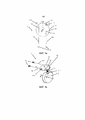
В дополнительном аспекте общая цель достигается посредством блока привода для использования в комбинации с дозирующим устройством, которое содержит дозирующий насосный блок и клапанный блок. Блок привода содержит блок привода насоса. Блок привода насоса содержит исполнительный механизм насоса и привод насоса, который соединен с исполнительным механизмом насоса. Привод насоса выполнен с возможностью зацепления с возможностью отсоединения поршня дозирующего насосного блока для передачи приводного усилия насоса и/или крутящего момента на валу привода насоса от исполнительного механизма насоса на поршень, перемещая таким образом поршень в дозирующем цилиндре дозирующего насосного блока. Блок привода дополнительно содержит блок привода клапана, как обсуждалось выше и дополнительно ниже. Выражение «дозирующий насосный блок» указывает, что блок подходит и выполнен для введения четко определенных объемов регулируемым образом. В обычной конструкции, которая предполагается далее, насосный блок представляет собой объемный насос шприцевого типа, где вводимый объем задан в виде результата (регулируемого и/или измеряемого) смещения поршня и площади поперечного сечения поршня.In a further aspect, the overall objective is achieved by a drive unit for use in combination with a dosing device that includes a dosing pump unit and a valve unit. The drive unit contains the pump drive unit. The pump drive unit contains a pump actuator and a pump drive, which is connected to the pump actuator. The pump drive is designed to engage with the possibility of detaching the piston of the metering pump unit to transfer the driving force of the pump and / or torque on the pump drive shaft from the pump actuator to the piston, thus moving the piston in the metering cylinder of the metering pump unit. The actuator assembly further comprises a valve actuator assembly as discussed above and further below. The expression "dosing pump unit" indicates that the unit is suitable and configured to deliver well-defined volumes in a controlled manner. In a conventional design, which is contemplated hereinafter, the pumping unit is a syringe-type positive displacement pump where the volume to be delivered is given as a result of (controlled and / or measurable) piston displacement and piston cross-sectional area.
Соединение привода насоса и поршня таково, что в зависимости от приводного усилия насоса и/или крутящего момента на валу привода насоса поршень смещается в проксимальном или противоположном дистальном направлении.The connection between the pump drive and the piston is such that, depending on the driving force of the pump and / or the torque on the pump drive shaft, the piston is displaced in the proximal or opposite distal direction.
Разъемное соединение дозирующего устройства и блока привода снабжает конструкцию модульного амбулаторного инфузионного насоса блоком длительного использования, который содержит блок привода и может содержать пользовательский интерфейс, контур управления и тому подобное и отдельный одноразовый блок, который выполнен для разового использования, например, только несколько дней, и может содержать дозирующее устройство и резервуар для жидкого лекарственного средства. Здесь и далее предполагается такой вариант осуществления. В отличие от одноразового блока блок длительного использования - также называемый дальше ниже насосное устройство - обычно выполняют для продолжительного срока службы, обычно несколько месяцев или даже лет.The detachable connection of the dispensing device and the drive unit provides the structure of the modular ambulatory infusion pump with a long-term unit, which contains the drive unit and may contain a user interface, a control loop and the like, and a separate disposable unit that is made for one-time use, for example, only a few days, and may contain a dispensing device and a reservoir for a liquid medication. Hereinafter, such an embodiment is assumed. In contrast to the disposable unit, the long-term unit - also referred to below as the pumping device - is usually made for a long service life, usually several months or even years.
Выражение «разъемное соединение», соответственно, относится к конструкции, которая обеспечивает механическое соединение и отсоединение дозирующего устройства и блока привода, причем отсоединение не вызывает повреждение по меньшей мере блока привода. С этой целью как на дозирующем устройстве, так и на блоке привода можно предоставить соответствующие механические установочные конструкции, как будет иллюстративно описано дополнительно ниже.The expression “detachable connection” accordingly refers to a structure that allows for mechanical connection and disconnection of the dispenser and the drive unit, the disconnection not causing damage to at least the drive unit. For this purpose, both on the metering device and on the drive unit, appropriate mechanical mounting structures can be provided, as will be illustrated further below.
Блок привода насоса и блок привода клапана функционально разделены в том, что приведение в действие не затрагивает блок привода клапана и наоборот. Исполнительный механизм насоса двигает только привод насоса, а первый и второй провод sma в качестве исполнительного механизма клапана двигают только поворотный элемент и привод клапана. Другими словами, блок привода выполнен с возможностью отдельного управления клапанным блоком и дозирующим насосным блоком дозирующего устройства.The pump drive unit and the valve drive unit are functionally separate in that actuation does not affect the valve drive unit and vice versa. The pump actuator only moves the pump drive, and the first and second sma wires as a valve actuator move only the pivot and valve drive. In other words, the drive unit is configured to separately control the valve unit and the metering pump unit of the metering device.
Блок привода может дополнительно содержать контур управления приводом клапана и приводом насоса. Хотя и не важно, исполнительный механизм насоса обычно представляет собой вращающийся исполнительный механизм, такой как стандартный двигатель постоянного тока, шаговый двигатель или бесщеточный двигатель постоянного тока. Контур управления может быть выполнен с возможностью управления блоком привода насоса и блоком привода клапана для управления многократным выполнением:The drive unit may further comprise a valve drive and pump drive control loop. Although not important, the pump actuator is usually a rotary actuator such as a standard DC motor, stepper motor, or brushless DC motor. The control loop can be configured to control the pump drive unit and the valve drive unit to control multiple executions:
A) управления передвижением блоком привода клапана корпуса отключения клапанного блока дозирующего устройства в положение наполнения;A) controlling the movement of the valve drive unit of the dispenser valve block shut-off body to the filling position;
B) управления, с корпусом отключения в положении наполнения, передвижением блоком привода насоса поршня внутри дозирующего цилиндра дозирующего насосного блока в дистальном направлении, увеличивая таким образом объем наполнения дозирующего цилиндра и наполнение дозирующего цилиндра жидким лекарственным средством;B) control, with the shut-off body in the filling position, by moving the piston pump drive unit inside the dosing cylinder of the dosing pump unit in the distal direction, thus increasing the filling volume of the dosing cylinder and filling the dosing cylinder with liquid medicine;
C) управления передвижением блоком привода клапана корпуса отключения из положение наполнения в положение опорожнения;C) controlling the movement of the shut-off body valve actuator assembly from the filling position to the empty position;
D) управления, с корпусом отключения в положении опорожнения, передвижением блоком привода насоса поршня внутри дозирующего цилиндра дозирующего насосного блока с рядом отдельных или поэтапных стадий дозирования в проксимальном направлении, уменьшая таким образом объем наполнения дозирующего цилиндра и введение дозы жидкого лекарственного средства из дозирующего цилиндра.D) control, with the shut-off body in the emptying position, by moving the piston pump drive unit inside the dosing cylinder of the dosing pump unit with a number of separate or staged dosing steps in the proximal direction, thus reducing the filling volume of the dosing cylinder and the introduction of a dose of liquid medicine from the dosing cylinder.
В такой последовательности в соответствии с требованиями терапевтического дозирования выполняют стадии дозирования, которые могут включать введение дозированного количества лекарственного средства по требованию за короткий период времени и/или введение дозированных возрастающих количеств лекарственного средства в течение продолжительного периода времени согласно, например, предварительно запрограммированному или непрерывно изменяемому графику дозирования. Кроме того, логика управления такова, что движения поршня (приведение в действие исполнительного механизма насоса) и движения корпуса отключения (приведение в действие либо первого, либо второго провода sma) не происходят параллельно, но только последовательно.In such a sequence, in accordance with the requirements of therapeutic dosing, dosing steps are performed, which may include administering a dosage amount of a drug on demand in a short period of time and / or administering dosed increasing amounts of a drug over an extended period of time according to, for example, a preprogrammed or continuously variable dosing schedule. In addition, the control logic is such that the movements of the piston (actuating the pump actuator) and the movements of the shutdown body (actuating either the first or second sma wire) do not occur in parallel, but only in series.
В варианте осуществления способ включает на стадии (b1), которая выполняется между стадиями (b) и (c), управление, с корпусом отключения в положении наполнения; передвижением блоком привода насоса поршня внутри дозирующего цилиндра дозирующего насосного блока в проксимальном направлении, заранее натягивая таким образом систему привода клапана. Посредством этой стадии компенсируют существенное ослабление, которое может произойти в системе.In an embodiment, the method comprises, in step (b1), which is performed between steps (b) and (c), operating with the shut-off body in a filling position; by moving the piston pump drive unit inside the dosing cylinder of the dosing pump unit in the proximal direction, thus pretensioning the valve drive system. This stage compensates for the significant weakening that can occur in the system.
В варианте осуществления конструкция блока привода такова, что привод насоса зацепляет поршень, а привод клапана зацепляет соединительный элемент привода клапана через общее относительное зацепляющее движение между блоком привода и дозирующим устройством. Зацепляющим движением может быть особенно прямолинейное относительное движение между блоком привода и дозирующим устройством.In an embodiment, the design of the drive unit is such that the pump drive engages the piston and the valve drive engages the valve drive connector via a common relative engaging movement between the drive unit and the metering device. The engaging movement can be a particularly rectilinear relative movement between the drive unit and the metering device.
Отсоединение блока привода и дозирующего устройства предпочтительно выполняется за счет прямолинейного относительного перемещающего движения в противоположном направлении. Такие отсоединяющее движение предпочтительно расцепляет привод насоса и поршень, а также привод клапана и соединительный элемент привода клапана.The disconnection of the drive unit and the dispensing device is preferably accomplished by a rectilinear relative movement in the opposite direction. Such a disengaging movement preferably disengages the pump drive and the piston as well as the valve drive and the valve drive connector.
Блок привода может дополнительно содержать и/или быть функционально соединен с другими компонентами, которые обычно имеются в амбулаторном инфузионном насосе, такими как общий контур управления и источник энергии. Блок привода может в частности содержать и/или быть функционально соединен с контрольным контуром и/или одним или более контрольными датчиками для отслеживания состояния блока привода насоса и/или блока привода клапана, такого как состояние клапана. Блок привода может дополнительно содержать и/или быть функционально соединен с контрольным контуром и/или одним или более контрольными датчиками для отслеживания состояния поршня и/или состояния клапана дозирующего устройства во время работы. Контур управления обычно основан на одном или более микроконтроллере (микроконтроллерах) и/или микрокомпьютере (микрокомпьютерах) с соответствующей прошивкой и/или программным кодом. Контур управления также может содержать, например, интерфейс беспроводной связи, дисплей, устройство звукового и/или тактильного предупреждения и один или более элементов ввода, таких как нажимные кнопки. Контур управления может быть выполнен специально для управления многократным выполнением последовательности, как объяснялось ранее.The drive unit can further comprise and / or be operatively connected to other components that are typically found in an ambulatory infusion pump, such as a common control loop and a power source. The drive unit may in particular comprise and / or be operatively connected to a monitoring loop and / or one or more monitoring sensors to monitor the status of the pump drive unit and / or the valve drive unit, such as the status of a valve. The drive unit may further comprise and / or be operatively connected to a control loop and / or one or more control sensors to monitor the piston state and / or the valve state of the dispensing device during operation. The control loop is typically based on one or more microcontroller (s) and / or microcomputer (s) with associated firmware and / or program code. The control loop may also comprise, for example, a wireless communication interface, a display, an audible and / or tactile warning device, and one or more input elements such as push buttons. The control loop can be designed specifically to control multiple executions of the sequence, as explained earlier.
Согласно дополнительному аспекту общая цель достигается посредством дозирующего устройства. Дозирующее устройство выполнено с возможностью соединения с блоком привода с возможностью отсоединения, как объяснено выше и дополнительно ниже. Дозирующее устройство содержит дозирующий насосный блок. Дозирующий насосный блок содержит дозирующий цилиндр и поршень. Поршень расположен в зацеплении внутри дозирующего цилиндра с уплотнением и с возможностью скольжения. Поршень дополнительно выполнен с возможностью зацепления в соединенном состоянии с приводом насоса блока привода. С этой целью поршень может специально содержать соединительный элемент привода насоса.In a further aspect, the overall objective is achieved by the dispensing device. The dispensing device is removably coupled to the drive unit as explained above and further below. The dosing device contains a dosing pump unit. The dosing pump unit contains a dosing cylinder and a piston. The piston is sealed and slidably engaged within the metering cylinder. The piston is additionally configured to engage in a connected state with the pump drive of the drive unit. For this purpose, the piston can specially comprise a pump drive connection.
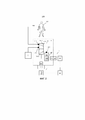
Дозирующее устройство дополнительно содержит клапанный блок, причем клапанный блок имеет заливной порт, при этом заливной порт выполнен с возможностью жидкостного соединения с резервуаром для жидкого лекарственного средства, сливной порт, при этом сливной порт выполнен с возможностью жидкостного соединения с контактной поверхностью места инфузии, и корпус отключения, причем корпус отключения может поворачиваться между положением наполнения, где он соединяет с возможностью прохождения жидкости заливной порт с дозирующим цилиндром, и альтернативным положением опорожнения, где он соединяет с возможностью прохождения жидкости дозирующий цилиндр со сливным портом.The dispensing device further comprises a valve block, wherein the valve block has a filling port, wherein the filling port is fluidly connected to the reservoir for a liquid drug, a drain port, wherein the drain port is fluidly connected to the contact surface of the infusion site, and a housing shut-off, the shut-off body being pivotable between a filling position where it fluidly connects the filler port to the dosing cylinder and an alternative emptying position where it fluidly connects the dosing cylinder to the drain port.
Дозирующее устройство дополнительно содержит соединительный элемент привода клапана. Соединительный элемент привода клапана соединен или представляет единое целое с корпусом отключения и выполнен с возможностью зацепления в соединенном состоянии с приводом клапанного блока привода таким образом, что поворот поворотного элемента передается на соединительный элемент привода клапана через привод клапана.The dosing device additionally contains a connecting element for the valve drive. The connecting element of the valve drive is connected or is integral with the shut-off body and is configured to engage in the connected state with the drive of the valve unit of the drive so that the rotation of the rotary member is transmitted to the connecting member of the valve drive through the valve drive.
Соединением между приводом клапана и соединительным элементом привода клапана таково, что функция передачи между приводом клапана и соединительным элементом привода клапана является непрерывной, т.е. непрерывное (поворачивающее) движение привода клапана приводит к соответствующему непрерывному движению соединительного элемента привода клапана и, соответственно, непрерывному движению корпуса отключения.The connection between the valve drive and the valve drive connection is such that the transfer function between the valve drive and the valve drive connection is continuous, i.e. the continuous (rotary) movement of the valve drive results in a corresponding continuous movement of the valve drive coupling and, accordingly, a continuous movement of the shut-off body.
Дополнительные аспекты дозирующего устройства обсуждаются выше и/или дополнительно ниже в контексте иллюстративных вариантов осуществления. Важно, что соединительный элемент привода насоса и соединительный элемент привода клапана в качестве интерфейсной системы блока привода насоса и блока привода клапана конструктивно и функционально отличаются, и движение поршня не вызывает движение корпуса отключения и наоборот. Кроме того, клапанный блок выполнен таким образом, что между положением наполнения и положением опорожнения не происходит движение, соответственно, перемещение жидкости. Переключение клапана, соответственно, не сопровождается перемещением.Additional aspects of the dispensing device are discussed above and / or further below in the context of illustrative embodiments. It is important that the pump drive connector and the valve drive connector as an interface system of the pump drive unit and the valve drive unit are structurally and functionally different, and the movement of the piston does not cause movement of the shut-off body and vice versa. In addition, the valve block is designed in such a way that no movement or movement of liquid occurs between the filling position and the emptying position. The valve switching, accordingly, is not accompanied by movement.
В варианте осуществления соединительный элемент привода клапана содержит воронкообразную конструкцию зацепления. Конструкция зацепления выравнивает соединительный элемент привода клапана и привод клапана друг относительно друга во время относительного зацепляющего движения между блоком привода и дозирующим устройством.In an embodiment, the valve actuator connector comprises a funnel-shaped engagement structure. The engagement design aligns the valve actuator coupling and the valve actuator with each other during a relative engaging movement between the actuator assembly and the dispenser.
Во время зацепляющего движения между блоком привода и дозирующим устройством привод клапана блока привода клапана, например, зацепляющий штифт, как объяснялось ранее, сперва входит в воронкообразную конструкцию зацепления в ее самой широкой секции. При зацепляющем движении вперед зацепляющий штифт двигается во все более узкую секцию конструкции зацепления, и просвет между зацепляющим штифтом и стенками конструкции зацепления сужается. Если требуется для относительных положений зацепляющего штифта и конструкции зацепления, зацепляющий штифт автоматически располагается и выравнивается конструкцией зацепления. В концевой секции воронкообразная конструкция зацепления может иметь параллельные стенки на расстоянии друг от друга таким образом, чтобы зацепляющий штифт в конце зацепляющего движения находился между боковыми стенками конструкции зацепления с небольшим зазором или люфтом. Соответственно, зацепляющее движение одновременно служит в качестве выравнивающего движения, которое выравнивает привод клапана и соединительный элемент привода клапана друг относительно друга. Во время последующей работы соединительный элемент привода клапана следует за движением привода клапана.During an engaging movement between the drive unit and the metering device, the valve drive of the valve drive unit, for example the engagement pin, as previously explained, first engages the funnel-shaped engagement structure at its widest section. With the engaging movement forward, the engaging pin moves into an increasingly narrow section of the engagement structure, and the gap between the engaging pin and the walls of the engaging structure is narrowed. If required by the relative positions of the engagement pin and the engagement design, the engagement pin is automatically positioned and aligned by the engagement design. In the end section, the funnel-shaped engagement structure may have parallel walls at a distance from each other so that the engaging pin at the end of the engaging movement is between the side walls of the engagement structure with little clearance or play. Accordingly, the engaging movement simultaneously serves as an alignment movement that aligns the valve actuator and the valve actuator coupling with each other. During subsequent operation, the valve drive connector follows the movement of the valve drive.
Любое движение зацепляющего штифта во время зацепляющего движения связано с соответствующим изменением длины первого и второго проводов sma. В этот момент предпочтительно, чтобы активированный (нагретый) провод sma мог прикладывать большое тянущее усилие, тогда как неактивированный провод sma мог пассивно деформироваться и в частности удлиняться, соответственно, растягиваться с небольшим усилием.Any movement of the engaging pin during the engaging movement is associated with a corresponding change in the length of the first and second sma wires. At this point, it is preferable that the activated (heated) sma wire can apply a large pulling force, whereas the non-activated sma wire can passively deform and in particular lengthen, respectively, stretch with little force.
В варианте осуществления клапанный блок содержит стопоры клапанов, причем стопоры клапанов блокируют дополнительный поворот корпуса отключения при приеме положения наполнения, соответственно, положения опорожнения.In an embodiment, the valve block comprises valve stoppers, the valve stoppers blocking further rotation of the shut-off body when receiving a filling position or an emptying position.
Альтернативно или дополнительно, в качестве части блока привода клапана можно предоставить стопоры привода клапана, которые ограничивают движение привода клапана, в частности в случае, когда он не соединен с дозирующим устройством.Alternatively or additionally, as part of the valve drive unit, it is possible to provide valve drive stoppers which restrict the movement of the valve drive, in particular when it is not connected to the metering device.
В дополнительном аспекте общая цель достигается посредством амбулаторного инфузионного насоса, в частности амбулаторной инсулиновой помпы. Амбулаторный инфузионный насос содержит блок привода и дозирующее устройство, как обсуждалось выше и дополнительно ниже. В обычном варианте осуществления инсулиновой помпы, амбулаторный инфузионный насос дополнительно содержит резервуар для лекарственного средства с объемом наполнения, например, от 1,5 мл до 3 мл жидкой готовой формы инсулина. В одном примере инсулиновой помпы дозирующее устройство имеет обычный объем наполнения (максимальный объем наполнения дозирующего цилиндра) в диапазоне от 0,05 мл до 0,2 мл, например, 0,075 мл в конкретном примере.In a further aspect, the overall goal is achieved by an ambulatory infusion pump, in particular an ambulatory insulin pump. The ambulatory infusion pump comprises a drive unit and a dispensing device as discussed above and further below. In a typical embodiment of an insulin pump, the ambulatory infusion pump further comprises a medicament reservoir with a fill volume of, for example, 1.5 ml to 3 ml of liquid formulated insulin. In one example of an insulin pump, the dispensing device has a typical fill volume (maximum fill volume of the dosing cylinder) in the range of 0.05 ml to 0.2 ml, such as 0.075 ml in a particular example.
КTO раткое описание фигурshort description of figures
На фиг. 1a, 1b представлен иллюстративный вариант осуществления блока привода клапана;FIG. 1a, 1b show an illustrative embodiment of a valve actuator assembly;
На фиг. 2 представлен амбулаторный инфузионный насос в функциональном видеFIG. 2 shows the ambulatory infusion pump in functional form
На фиг. 3 представлен вариант осуществления насосного устройства и дозирующего устройства на виде в перспективе;FIG. 3 is a perspective view of an embodiment of a pumping device and a dispensing device;
На фиг. 4 представлено устройство фиг. 3 с удаленным кожухом на виде в перспективе;FIG. 4 shows the device of FIG. 3 with shroud removed in perspective view;
На фиг. 5 представлен дополнительный вариант осуществления блока привода клапана в рабочем соединении с дозирующим устройством на виде в перспективе;FIG. 5 is a perspective view of a further embodiment of a valve drive unit in operative connection with a dispensing device;
На фиг. 6 представлена секция блока привода клапана;FIG. 6 shows a section of the valve drive unit;
На фиг. 7 представлен вид спереди насосного устройства и дозирующего устройства;FIG. 7 is a front view of the pumping device and the metering device;
На фиг. 8 представлено дозирующее устройство на виде в перспективе.FIG. 8 is a perspective view of the dispensing device.
Подробное раскрытие настоящего изобретенияDetailed Disclosure of the Present Invention
Далее иллюстративные варианты осуществления обсуждаются более подробно с дополнительной ссылкой на фигуры.In the following, illustrative embodiments are discussed in more detail with additional reference to the figures.
Следует заметить, что в следующем описании термины, обозначающие направление, положение или ориентацию, такие как «левый», «правый», «верхний», нижний», «верх», «низ», «проксимальный», «дистальный» предназначены исключительно для улучшения понимания читателя и относятся к исключительно к фигурам. Они не подразумевают какие-либо конкретные направления или ориентации для применения.It should be noted that in the following description, terms denoting direction, position, or orientation such as "left", "right", "upper", lower "," up "," down "," proximal "," distal "are intended solely to improve understanding of the reader and refer exclusively to figures. They do not imply any particular direction or orientation for use.
Далее сперва сделана ссылка на фиг. 1a и фиг. 1b, показывающие иллюстративный вариант осуществления блока 1 привода клапана на схематичном виде сверху (фиг. 1a) и виде в перспективе (фиг. 1b), соответственно.Next, reference is first made to FIG. 1a and FIG. 1b showing an illustrative embodiment of the
Блок 1 привода клапана содержит первый провод 10a sma и второй провод 10b sma, которые оба иллюстративно расположены вдоль прямой линии и параллельно друг другу и в комбинации образуют исполнительный механизм клапана. Один конец первого, соответственно, второго провода 10a, 10b sma соединен с поворотным элементом 12 через соответствующую соединительную конструкцию 14a, 14b sma соответственно. Иллюстративно, соединительные конструкции 14a, 14b sma выполнены в виде штифтов, которые выступают из (иллюстративно дискообразного) главного корпуса 12' поворотного элемента 12. Поворотный элемент 12 расположен с возможностью поворота вокруг неподвижной оси a поворотного элемента, а соединительные конструкции 14a, 14b sma расположены на противоположных сторонах оси a поворотного элемента, причем каждое расстояние до оси a поворотного элемента образует плечо рычага. (тянущее) усилие, которое прикладывают к первой, соответственно, второй соединительной конструкции 14a, соответственно, 14b sma, соответственно заставляет поворотный элемент 12 поворачиваться вокруг оси a поворотного элемента в противоположных направлениях, преобразуя таким образом прямолинейное движение проводов 10a, 10b sma в поворотное движение. Противоположный конец каждого первого провода 10a sma и второго провода 10b sma соединен с неподвижной опорной конструкцией 11. Иллюстративно стержнеобразный привод 13 клапана расположен на расстоянии от оси a поворотного элемента и выступает параллельно оси a поворотного элемента из главного корпуса 12'. Главный корпус 12' и привод 13 клапана в комбинации образуют коронную шестерню с приводом 13 клапана в качестве единственного зуба. Привод 13 клапана и соединительные конструкции 14a, 14b sma образованы в виде единого целого с главным корпусом 12' или жестко прикреплены к нему, образуя таким образом общий конструктивный блок.The
Вместе с блоком 1 привода клапана показан соединительный элемент 312 привода клапана клапанного блока. Соединительный элемент 312 привода клапана иллюстративно исполнен в виде диска, который выполнен с возможностью поворота вокруг оси b корпуса отключения. Ось b корпуса отключения может совпадать с осью дозирующего устройства (не показано). Соединительный элемент 312 привода клапана содержит конструкцию 313 зацепления привода клапана. Конструкция зацепления привода клапана исполнена в виде паза в окружности соединительного элемента 312 привода клапана и выполнена с возможностью разъемного зацепления с приводом 13 клапана с небольшим люфтом. Ось b корпуса отключения иллюстративно перпендикулярна и пересекается с осью a поворотного элемента.Together with the
В показанной конфигурации второй провод 10b sma иллюстративно активирован (нагрет) и, таким образом, укорочен. Следовательно, поворотный элемент 12 поворачивается вокруг оси a поворотного элемента в указанном направлении. По причине зацепления между приводом 13 клапана и конструкцией 313 зацепления привода клапана соединительный элемент 312 привода клапана также вращается вокруг оси b корпуса отключения, как указано. В то же самое время (на активированный) первый провод 10a sma пассивно удлинен. Чередующаяся приведение в действие первого провода 10a sma с не активированным вторым проводом 10b sma будет приводить к повороту элемента 12 и соединительного элемента 312 привода клапана в противоположных направлениях, причем второй провод 10b sma пассивно удлиняется.In the configuration shown, the
Далее сделана дополнительная ссылка на фиг. 2. На фиг. 2 представлено амбулаторное инфузионное насосное устройство, функционально соединенное с пациентом на симметричном функциональном виде.Further reference is now made to FIG. 2. In FIG. 2 shows an outpatient infusion pumping device functionally connected to a patient in a symmetrical functional view.
Амбулаторное инфузионное насосное устройство содержит дозирующее устройство 3 и блок привода, причем блок привода содержит блок 2 привода насоса и блок 1 привода клапана. Амбулаторное инфузионное насосное устройство в рабочем состоянии содержит резервуар 5 для жидкого лекарственного средства. Следует заметить, что показаны только те конструктивные и функциональные блоки, которые имеют особое значение с точки зрения настоящего раскрытия. Также обычно имеются другие блоки, такие как источник энергии, пользовательский интерфейс и т.д.The outpatient infusion pump device comprises a
Дозирующее устройство 3 содержит дозирующий насосный блок 30 и клапанный блок 31. Дозирующий насосный блок 30 содержит дозирующий цилиндр 300 и поршень 302, расположенный с уплотнением и с возможностью скольжения внутри дозирующего цилиндра 300 наподобие шприца. В проксимальной передней стенке дозирующего цилиндра 300 расположено отверстие в виде порта 301 насоса, которое соединяет по текучей среде внутренний объем дозирующего цилиндра 300 с клапанным блоком 31. Клапанный блок 31 может быть поочередно в состоянии 315b наполнения (корпус 315 отключения в положении наполнения) или в состоянии 315a опорожнения (корпус 315 отключения в положении опорожнения). Во время работы клапанный блок 31 многократно переключается между этими состояниями. Резервуар 5 соединен по текучей среде с клапанным блоком 31 через заливной порт 310. Пациент 900 соединен по текучей среде с клапанным блоком 31 через сливной порт 311 и контактную поверхность 890 места инфузии. Следует заметить, что контактная поверхность 890 места инфузии иллюстративно показана в виде единого целого с инфузионной системой, например, катетером. Альтернативно, инфузионным насосным устройством может быть насос с пластырем, который прикрепляют непосредственно к телу пациента, например, посредством липкой подкладки. В данном случае контактной поверхностью места инфузии может быть непосредственно канюля.The
Клапанный блок 31 содержит корпус 315 отключения, который расположен с уплотнением и с возможностью вращения в подшипнике клапана. Корпус 315 отключения содержит конфигурацию с проточным каналом, который принимает в зависимости от углового положения корпуса отключения либо состояние 315b наполнения, либо состояние 315a опорожнения, соответственно. Клапанный блок 31 обычно расположен на одной линии с дозирующим устройством 30 и проксимально от него. В обычной конфигурации, которая также предполагается далее, ось корпуса отключения параллельна и необязательно совпадает с продольной осью дозирующего цилиндра 300, вдоль которой перемещается поршень 302. Однако, такое расположение не является существенным.The
Дозирующее устройство 3 в качестве части клапанного блока 31 дополнительно содержит соединительный элемент 312 привода клапана для переключения клапанного блока 31 между положением 315b наполнения и положением 315a опорожнения. Аналогично, дозирующее устройство 3 в качестве части дозирующего насосного блока 30 содержит соединительный элемент 303 привода насоса для перемещения поршня 302 внутри дозирующего цилиндра 300, как объяснялось ранее. Соединительный элемент 303 привода насоса полностью или частично может составлять единое целое с поршнем 302.The
Работа дозирующего насосного блока 30 и клапанного блока 31 происходит независимо друг от друга. То есть поршень 302 может перемещаться внутри дозирующего цилиндра 300, не влияя на состояние клапанного блока 31. Также, состояние клапанного блока 31 можно изменять, соответственно, переключать, не влияя на положение поршня 302 внутри дозирующего цилиндра 300. Кроме того, переключение клапана между состоянием наполнения и состоянием опорожнения не включает перемещение жидкости между заливным портом 310 и сливным портом 311, обусловленное движением корпуса 315 отключения. Следовательно, переключение клапана не включает введение дозы жидкости пациенту. Этот аспект имеет особое значение, потому что регулируемое введение отмеренной дозы выполняется исключительно за счет регулируемого перемещения поршня 302. Для сильно концентрированных лекарственных средств, таких как обычные жидкие готовые формы инсулина, непреднамеренное введение лекарственного средства, обусловленное переключением клапана, может приводить к нежелательным и возможно тяжелым медицинским осложнениям.The
В обычной конфигурации дозирующее устройство 3 с дозирующим насосным блоком 30 и клапанным блоком 31 образовано в виде компактного устройства и в виде единого целого. Вследствие этого, порт 301 насоса в отличие от заливного порта 310 и сливного порта 311 не доступен снаружи дозирующего устройства 3.In a typical configuration, the
Что касается клапанного блока 31 кроме того следует заметить, что на фиг. 2 представлены только состояния 315a, 315b, когда либо заливной порт 310, либо сливной порт 311 соединен с портом 301 насоса. Однако, в дополнительном промежуточном состоянии все три порта 301, 310, 311 закрыты, что приводит к гидравлической изоляции.As regards the
Блок 2 привода насоса содержит привод 21 насоса, который выполнен с возможностью разъемного зацепления соединительного элемента 303 привода насоса для перемещения поршня внутри дозирующего цилиндра 300, как объяснялось ранее. Блок 2 привода насоса дополнительно содержит исполнительный механизм 20 насоса, обычно двигатель, как упоминалось ранее. Исполнительный механизм насоса может дополнительно содержать редуктор и/или механизм преобразования вращения в прямолинейное движение. В целом блок 2 привода насоса обычно выполняют в виде шпиндельного привода или винтового привода, который преобразует вращательное движение исполнительного механизма в реверсивное прямолинейное поступательное движение привода 21 насоса и поршня 302 через соединительный элемент 303 привода насоса. Привод 21 насоса может быть реализован в виде плунжера. Соединительный элемент 303 привода насоса может быть прочно прикреплен или встроен на дистальной части поршня 302. Привод 21 насоса и соединительный элемент 303 привода насоса разработаны для возвратно-поступательного соединения, например, в виде байонетного соединения, замкового соединения и тому подобное. Возвратно-поступательное движение привода 21 насоса приводит к соответствующему возвратно-поступательному движению поршня в проксимальном или дистальном направление, соответственно.The
Блок 1 привода клапана выполнен в соответствии с настоящим раскрытием и содержит поворотный элемент 12 и привод 13 клапана и первый и второй провод 10a, 10b sma, которые в комбинации образуют исполнительный механизм клапана.The
Исполнительный механизм 20 насоса и первый и второй провод 10a, 10b sma в качестве исполнительного механизма клапана соединены с блоком управления или контуром 40 управления, который управляет их работой.The
Блок 2 привода насоса, блок 1 привода клапана и контур 40 управления обычно относятся к обычному компактному устройству, которое также называется «насосное» устройство» и образует часть амбулаторного инфузионного насосного устройства, которое выполнено для продолжительного срока службы в течение ряда месяцев, например, шести месяцев, или лет, тогда как дозирующее устройство 3 и резервуар 5 являются одноразовыми с существенно меньшим сроком службы.The
Далее сделана дополнительная ссылка на фиг. 3 и фиг. 4. На фиг. 3 представлены основные компоненты иллюстративного варианта осуществления амбулаторного инфузионного насоса на схематичном виде в перспективе. Амбулаторное инфузионное насосное устройство выполнено в соответствии с фиг. 2, как обсуждалось ранее.Further reference is now made to FIG. 3 and FIG. 4. In FIG. 3 depicts the main components of an illustrative embodiment of an ambulatory infusion pump in a schematic perspective view. The ambulatory infusion pump device is configured in accordance with FIG. 2, as discussed earlier.
На фигурах проксимальное направление обозначено «p», а дистальное направление обозначено «d». Амбулаторный инфузионный насос содержит многоразовое насосное устройство 4, которое выполнено для продолжительного срока службы, составляющего обычно ряд лет, и, вследствие этого, также называемое «блок длительного использования». В качестве примера амбулаторным инфузионным насосом является инсулиновая помпа, которую человек с диабетом носит по существу непрерывно день и ночь. Общий размер инфузионного насоса такой, что его можно носить скрытно от глаз, например, в кармане брюк с зажимом для крепления к ремню и тому подобное, или можно прикреплять к телу в виде насоса с пластырем.In the figures, the proximal direction is indicated by "p" and the distal direction is indicated by "d". The ambulatory infusion pump comprises a reusable pumping device 4 that is designed for a long service life, usually a number of years, and therefore also referred to as a "long-term unit". As an example, an outpatient infusion pump is an insulin pump that is worn by a person with diabetes substantially continuously day and night. The overall size of the infusion pump is such that it can be worn discreetly, for example, in a trouser pocket with a belt clip and the like, or can be attached to the body as a pump with a patch.
Насосное устройство 4 имеет кожух (не показан), который несет такие компоненты, как источник энергии и пользовательский интерфейс. Насосное устройство 4 в частности имеет встроенный блок 1 привода клапана, блок 2 привода насоса и контур управления или блок 40 управления, как обсуждалось ранее со ссылкой на фиг. 2. Амбулаторный инфузионный насос дополнительно содержит дозирующее устройство 3, которое выполнено для срока службы, обычно составляющем от нескольких дней до, например, двух недель. Обусловленное их разным временем применения, насосное устройство 4 и в частности блок 2 привода насоса с одной стороны и дозирующее устройство 3 с другой стороны разработаны для разъемного механического и функционального соединения.The pumping device 4 has a casing (not shown) that carries components such as a power source and a user interface. The pumping device 4 in particular has an integral
На фиг. 3 и фиг. 4 представлен амбулаторный инфузионный насос с насосным устройством 4 и дозирующим устройством 3, немного отстоящими друг от друга, т.е. в несоединенном состоянии, но с относительной ориентацией, которая соответствует ориентации во время применения. В отличие от фиг. 4 компоненты кожуха насосного устройства 4 и одноразового блока 3 удалены.FIG. 3 and FIG. 4 shows an ambulatory infusion pump with pumping device 4 and
В дополнение к компонентам, которые показаны на фиг. 2, 3, амбулаторный инфузионный насос в рабочем состоянии содержит резервуар 5 для лекарственного средства. Показанный вариант осуществления разработан для использования в комбинации с цилиндрическим картриджем для лекарственного средства, например, с объемом наполнения от 1,5 мл до 3 мл. Картридж для лекарственного средства соединен с дозирующим устройством 3 посредством соединительного элемента 32 картриджа, который содержит механическую и гидравлическую интерфейсную систему. В соединенном состоянии картридж проходит вдоль проксимально-дистального направления. Гидравлическая интерфейсная система содержит полую канюлю (не показано) для прокалывания перемычки картриджа для лекарственного средства, соединяя по текучей среде таким образом внутренний объем картриджа для лекарственного средства с впускным портом 310 дозирующего устройства 3.In addition to the components shown in FIG. 2, 3, the ambulatory infusion pump in working order contains a
Соединение насосного устройства 4 и дозирующего устройства 3 достигается за счет прямолинейного движения дозирующего устройства 3 относительно насосного устройства 4 в дистальном направлении, которое показано пунктирной стрелкой. Насосное устройство 4 содержит гнездо 41 картриджа, которое принимает картридж для лекарственного средства, и гнездо 41a дозирующего цилиндра, которое принимает дозирующий насосный блок 30 дозирующего устройства 3 на время применения дозирующего устройства 3 и картриджа.The connection of the pumping device 4 and the
Для механического соединения или установки насосное устройство 4 и дозирующее устройство 3 снабжены конструкцией 42 для установки насосного устройства, которое выполнено с возможностью приема цилиндра 300 насоса и необязательного блока 33 датчиков. В собранном состоянии насосное устройство 4 и дозирующее устройство 3 в комбинации образуют водонепроницаемый или водостойкий узел во время применения. Отсоединение выполняют за счет соответствующего прямолинейного движения в противоположном направлении дозирующего устройства 3 относительно насосного устройства 4 в проксимальном направлении, которое возможно включает разблокировку с высвобождением защелкивающихся элементов, захватов. Необязательный блок 33 датчиков содержит вытянутую пластину, которая проходит параллельно дозирующему цилиндру 300 и может содержать, например, передающую гидравлическое давление мембрану, датчик расхода или расходомер и/или пневмодатчик. В качестве противоэлемента сопряжения с конструкцией 42 установки насосного устройства дозирующее устройство 3 содержит соответствующую конструкцию установки дозирующего устройства. В этом варианте осуществления проксимальный конец блока 33 датчиков соединен с другими компонентами дозирующего устройства 3, в частности с дозирующим насосным блоком 30 и с одноразовым кожухом 35. Одноразовый кожух 35 содержит на своем дистальном конце кольцевое уплотнение 34.For mechanical connection or installation, the pumping device 4 and the
В дополнение к упомянутым ранее элементам дозирующее устройство 3 содержит дозирующий насосный блок 30 и клапанный блок 31. Все дозирующее устройство 3 предпочтительно выполнено и предоставлено в виде общего единого блока. Дозирующее устройство 3 выполнено в виде встроенного устройства с клапанным блоком 31, расположенным проксимально от дозирующего насосного блока 30. Резервуар для лекарственного средства, в частности картридж для лекарственного средства может быть предоставлен, уже соединенным с соединительным элементом 32 картриджа, или может быть отдельным, и его соединяет пользователь. Общая конфигурация и конструкция дозирующего устройства 30 выполнена в соответствии с фиг. 2 и соответствующим описанием.In addition to the previously mentioned elements, the
Далее сделана дополнительная ссылка на фиг. 5, иллюстрирующую взаимодействие между блоком 1 привода клапана и клапанным блоком 31. Соединительный элемент 312 привода клапана содержит щелеобразную конструкцию 313 зацепления привода клапана, которая обсуждается еще более подробно ниже и зацепляет в соединенном состоянии, как показано на фиг. 5, стержнеобразный привод 13 клапана, который выступает из корпуса поворотного элемента 12 в конструкцию 313 зацепления привода клапана. Корпус 315 отключения клапанного блока 31 образован в виде единого целого с соединительным элементом 312 привода клапана, а сам на фиг. 3, 4 не показан.Further reference is now made to FIG. 5 illustrating the interaction between the
В этом показанном примере дозирующее устройство 3 выполнено в виде встроенной конструкции с совпадающей осью перемещения поршня (соответствующей продольной оси дозирующего цилиндра 300 и проходящей между дистальным и проксимальным концом), соответственно, идентичной оси b корпуса отключения (см. Также фиг. 1, 7), как объяснялось ранее в контексте фиг. 2.In this example shown, the
В отличие от варианта осуществления фиг. 1a, 1b каждый из первого провода 10a sma и второго провода 10b sma по существу u-образный. Для каждого из первого провода 10a sma и второго провода 10b sma основание u-образных проводов sma (область, где встречаются оба ответвления «u») соединено с поворотным элементом 12 через соединяющий элемент 14a, 14b sma в виде крюков, на которые опираются основания первого провода 10a sma и второго провода sma. Крюки, как и штифты варианта осуществления фиг. 1a, 1b, расположены на противоположных сторонах оси a поворотного элемента, преобразуя таким образом укорачивание первого провода 10a sma, соответственно, второго провода 10b sma в поворотные движения в противоположных направлениях, причем другой из первого провода 10a sma и второго провода 10b sma пассивно удлиняется. За счет зацепления между приводом 13 клапана и соединительным элементом 312 привода клапана, соответственно, конструкции 313 зацепления, поворотное движение поворотного элемента 12 приводит к соответствующему повороту соединительного элемента 312 привода клапана и корпуса 315 отключения вокруг оси b корпуса отключения.In contrast to the embodiment of FIG. 1a, 1b each of the
От поворотного элемента 12 ответвления проводов 10a, 10b sma продолжаются параллельно в дистальном направлении и отдельно соединены с опорной конструкцией 11, которая иллюстративно выполнена в виде печатной платы. Опорная конструкция 11 может быть частью или жестко соединена с другими частями конструкции насоса и в частности жестко соединена с кожухом 4 насосного устройства. Опорная конструкция является достаточно жесткой для поглощения усилий, которые прикладывают первый и второй провод 10a, 10b sma без существенной деформации.From the
Поворотный элемент 12 в целом или по меньшей мере соединительные конструкции 14a, 14b sma предпочтительно сделаны из металла или покрыты металлом таким образом, что ток нагревания в проводах 10a, 10b sma укорачивается, как объяснялось ранее в общем описании.The
Далее сделана дополнительная ссылка на фиг. 6. На фиг. 6 в подробном изображении показана дистальная концевая секция первого провода 10a sma и опорная конструкция 11. Близко к свободным концам каждое ответвление провода 10a, 10b sma имеет утолщение, которое иллюстративно выполнено в виде втулки 15, которая прочно соединена с соответствующим проводом sma, например, путем опрессовки или пайки. Посредством втулки 15 каждое ответвление первого провода 10a sma зацеплено в иллюстративном щелеобразном пазу (не показано), который расположен на свободной концевой секции первой листовой пружины 16a. Противоположный конец первой листовой пружины 16a прочно прикрепляют к опорной конструкции 11, например, посредством прикручивания, клепания, зажима и тому подобное. Близко к свободному концу каждая из двух листовых пружин опирается на опорный элемент, который иллюстративно выполнен в виде куполообразной заклепки 17. Как лучше всего видно на фиг. 4, такой же принцип применим ко второму проводу 10b sma, который соединен с опорной конструкцией посредством вторых листовых пружин 16b.Further reference is now made to FIG. 6. In FIG. 6 shows in detail the distal end section of the
В невытянутом состоянии провода 10a sma первые листовые пружины 16a опираются на соответствующие заклепки 17 с номинальным усилием контакта, которое действует в дистальном направлении и в то же самое время является пороговым усилием и переключающим усилием, как объяснялось ранее в общем описании. В комбинации первые листовые пружины 16a, соответственно, служат в качестве первой пружинной конструкции, которая растягивает первый провод 10a sma за счет приложения усилия в дистальном направлении. Аналогично, вторые листовые пружины 16b служат в качестве второй пружинной конструкции, которая растягивает второй провод 10b sma.In the unstretched state of the
Первая и вторая листовые пружины 16a, 16b и заклепки 17 обычно сделаны из металла и, вследствие этого, являются электропроводными и/или имеют электропроводное покрытие. Контур управления приводом клапана (функциональный компонент блока управления или контура 40 управления, см. Фиг. 2) соединен с заклепками 17. Для активации/приведения в действие первого провода 10a sma источник электроэнергии соединен с заклепками 17, устанавливая таким образом прохождение тока из источника энергии через одну из заклепок 17 и соответствующую первую листовую пружину 16a, первый провод 10a sma, другую первую листовую пружину 16a и соответствующую заклепку 17 и назад в источник энергии.The first and
Как объяснялось ранее, укорачивание активированного первого провода 10a sma приводит к поворотному движению блока поворотного элемента 12, дальнейшее движение блокируется. В то же самое время усилие контакта между первыми листовыми пружинами 16a и соответствующими заклепками 17 уменьшается вследствие тянущего усилия, которое прикладывает первый провод 10a sma. Дополнительное уменьшение длины активированного первого провода 10a sma приводит к подъему первых листовых пружин 16a и ослаблению контакта с соответствующими заклепками 17, что приводит к прерыванию прохождения тока и прекращению нагревания первого провода 10a sma. То же самое аналогичным образом применимо ко второму проводу 10b sma. Листовые пружины 16a, 16b, соответственно, служат в качестве переключателей конечного положения или датчиков конечного положения, которые выявляют, принял ли корпус 315 отключения какое-либо из конечных положений.As previously explained, shortening the activated
Дополнительный предпочтительный результат показанной конфигурации возникает, когда все насосное устройство 4 (или блок привода в виде заранее собранного подблока) подвергают действию высокой температуры, например, во время хранения или транспортировки, за пределами температуры активации/приведения в действие. Как объяснялось ранее, и первый провод 10a sma и второй провод 10b sma будут активированы и, соответственно, будут укорачиваться. Как ясно, например, из фиг. 4, такая ситуация приводит к существенному механическому напряжению на всю опорную конструкцию 11, провода 10a sma и поворотный элемент 12, содержащий подшипник. Без упругости листовых пружин 16a, 16b в этой ситуации конструкцию можно сильно повредить. Однако, и первая и вторая листовые пружины 16a, 16b в этом случае будут вытягиваться и подниматься с заклепок 17, ограничивая таким образом тянущее усилие, которое прикладывает первый и второй провода 10a, 10b sma до приемлемого значения в пределах ограничений конструкции.A further advantageous result of the shown configuration occurs when the entire pumping device 4 (or a pre-assembled subunit drive unit) is exposed to a high temperature, for example during storage or transportation, outside the activation / actuation temperature. As previously explained, both the first 10a sma wire and the second 10b sma wire will be activated and shortened accordingly. As is clear from, for example, FIG. 4, this situation results in significant mechanical stress on the
Далее сделана дополнительная ссылка на фиг. 7. На фиг. 7 представлена конфигурация фиг. 4 на виде спереди (если смотреть в направлении от проксимального к дистальному концу), причем привод 13 клапана зацепляет конструкцию 313 зацепления соединительного элемента 312 привода клапана.Further reference is now made to FIG. 7. In FIG. 7 shows the configuration of FIG. 4 in a front view (viewed from the proximal to the distal end), with the
Дозирующее устройство 3 содержит стопорную конструкцию, которая иллюстративно выполнена в виде кольцевой секции 314 с единым центром с дозирующим цилиндром 300 и осью b корпуса отключения (иллюстративно идентичную с осью дозирующего цилиндра и осью перемещения поршня). Концы 314a, 314b кольцевой секции 314 служат в качестве стопоров клапанов, которые блокируют дальнейшее движение соединительного элемента 312 привода клапана - а в зацепленном состоянии поворотного элемента 12 с приводом 13 клапана - при соответствующей поверхности соединительного элемента 312 привода клапана ударяют стопор. На фиг. 7 соединительный элемент 312 привода клапана показан в конфигурации, где он ударяет стопор 314a верхнего клапана.The
Далее сделана дополнительная ссылка на фиг. 8. На фиг. 8 представлено дозирующее устройство 3 на виде в перспективе. Можно видеть, что конструкция 313 зацепления представляет собой воронкообразный паз, имеющий проксимальную часть 313a с параллельными боковыми стенками и трапециевидную дистальную часть 313b со сходящимися боковыми стенками. На дистальном конце ширина дистальной части 313b самая широкая. На проксимальном конце дистальной части 313b ее ширина соответствует ширине проксимальной части 313a. При соединении дозирующего устройства 3 с насосным устройством 4 путем вставки дозирующего устройства 3, содержащего гнездо 41a дозирующего цилиндра (см. Фиг. 3), соединительный элемент 13 привода клапана (не показано на фиг. 8) сперва вводят в трапециевидную дистальную часть 313b и направляют в проксимальную часть 313a, где он остается для последующей работы. Во время этой вставки и процесса соединения поворотный элемент 12 с приводом 13 клапана и соединительный элемент 312 привода клапана выравнивают друг относительно друга, как объяснялось ранее.Further reference is now made to FIG. 8. In FIG. 8 shows a
Когда соединение завершают (а дозирующий цилиндр 300 располагают в гнезде 41a дозирующего цилиндра), привод 12 клапана и соединительный элемент 312 привода клапана находятся в правильном зацеплении и относительном выравнивании, но обычно в неопределенном состоянии. То есть корпус отключения (и, соответственно, привод 12 клапана и соединительный элемент 312 привода клапана) могут быть в любом положении между положением наполнения и положением опорожнения. При активации привода 1 клапана в первый раз потребуется, соответственно, меньше чем полный ход до тех пор, пока корпус отключения не примет положение наполнения или положение опорожнения в качестве какого-либо из его конечных положений, и дальнейшее движение блокируется. В описанном здесь варианте осуществления достижение какого-либо из конечных положений автоматически приводит к прерыванию подачи энергии. Альтернативно или дополнительно, однако, контрольный датчик, который отслеживает положение корпуса 315 отключения (или эквивалентно соединительного элемента 312 привода клапана), такой как световой барьер выделенных концевых переключателей и тому подобное, может присутствовать в качестве части блока управления или контура 40 управления.When the connection is complete (and the
Claims (27)
Applications Claiming Priority (3)
| Application Number | Priority Date | Filing Date | Title |
|---|---|---|---|
| EP16173361.3 | 2016-06-07 | ||
| EP16173361 | 2016-06-07 | ||
| PCT/EP2017/063440 WO2017211711A1 (en) | 2016-06-07 | 2017-06-02 | Valve drive unit with shape memory alloy actuator |
Publications (3)
| Publication Number | Publication Date |
|---|---|
| RU2018146114A RU2018146114A (en) | 2020-07-10 |
| RU2018146114A3 RU2018146114A3 (en) | 2020-07-10 |
| RU2736607C2 true RU2736607C2 (en) | 2020-11-19 |
Family
ID=56112886
Family Applications (1)
| Application Number | Title | Priority Date | Filing Date |
|---|---|---|---|
| RU2018146114A RU2736607C2 (en) | 2016-06-07 | 2017-06-02 | Valve drive unit with shape memory alloy actuator |
Country Status (7)
| Country | Link |
|---|---|
| US (1) | US11071819B2 (en) |
| EP (1) | EP3463504A1 (en) |
| JP (1) | JP6920353B2 (en) |
| AU (1) | AU2017277381B2 (en) |
| BR (1) | BR112018073547A2 (en) |
| RU (1) | RU2736607C2 (en) |
| WO (1) | WO2017211711A1 (en) |
Cited By (1)
| Publication number | Priority date | Publication date | Assignee | Title |
|---|---|---|---|---|
| RU207605U1 (en) * | 2021-01-11 | 2021-11-03 | Российская Федерация, от имени которой выступает Государственная корпорация по атомной энергии "Росатом" | ROTARY DRIVE EXECUTIVE MECHANISM WITH ALLOY ELEMENTS WITH SHAPE MEMORY EFFECT |
Families Citing this family (3)
| Publication number | Priority date | Publication date | Assignee | Title |
|---|---|---|---|---|
| EP3335746B1 (en) | 2016-12-14 | 2020-05-06 | Roche Diabetes Care GmbH | Ambulatory infusion device |
| US20220118176A1 (en) * | 2019-05-17 | 2022-04-21 | Medtrum Technologies Inc. | Bilaterally driven drug infusion device with multiple infusion modes |
| US20210154401A1 (en) * | 2019-11-27 | 2021-05-27 | Fluid-O-Tech S.R.L. | Device for the administration of liquids, drugs or nutrients to a patient |
Citations (3)
| Publication number | Priority date | Publication date | Assignee | Title |
|---|---|---|---|---|
| WO2011101641A2 (en) * | 2010-02-22 | 2011-08-25 | The University Of Nottingham | Microfluidic delivery systems |
| RU2447905C2 (en) * | 2006-02-09 | 2012-04-20 | Дека Продактс Лимитед Партнершип | Pump systems for fluid delivery and methods for using stress application devices |
| EP2881128A1 (en) * | 2013-12-04 | 2015-06-10 | F. Hoffmann-La Roche AG | Ambulatory infusion system including a step switching mechanism for valve control |
Family Cites Families (17)
| Publication number | Priority date | Publication date | Assignee | Title |
|---|---|---|---|---|
| DE69907427T2 (en) | 1998-02-02 | 2004-03-18 | Medtronic, Inc., Minneapolis | IMPLANTABLE INFUSION DEVICE WITH A SAFETY VALVE |
| WO2002057627A1 (en) * | 2001-01-17 | 2002-07-25 | M 2 Medical A/S | Shape memory alloy actuator |
| US7052251B2 (en) | 2002-04-22 | 2006-05-30 | Medtronic Minimed, Inc. | Shape memory alloy wire driven positive displacement micropump with pulsatile output |
| US6656158B2 (en) | 2002-04-23 | 2003-12-02 | Insulet Corporation | Dispenser for patient infusion device |
| US7905868B2 (en) | 2006-08-23 | 2011-03-15 | Medtronic Minimed, Inc. | Infusion medium delivery device and method with drive device for driving plunger in reservoir |
| EP1993633B1 (en) | 2006-02-09 | 2016-11-09 | Deka Products Limited Partnership | Pumping fluid delivery systems and methods using force application assembly |
| EP1970677B1 (en) | 2007-03-15 | 2009-10-07 | F. Hoffmann-La Roche AG | Intravenous infusion system with dosing device |
| US7632585B2 (en) | 2007-04-11 | 2009-12-15 | Eveready Battery Co., Inc. | Battery having fluid regulator with pressure equalization |
| US20090221986A1 (en) | 2007-10-04 | 2009-09-03 | Baxter International Inc. | Method and apparatus for a fluid delivery system with controlled fluid flow rate |
| US7828792B2 (en) * | 2008-07-25 | 2010-11-09 | Medasys Incorporated | MRI compatible programmable valve pump |
| EP2361646B1 (en) * | 2008-09-12 | 2013-03-20 | Roche Diagnostics GmbH | Dosing unit and ambulatory infusion device comprising dosing unit |
| US8250782B2 (en) * | 2009-03-26 | 2012-08-28 | Reebok International Limited | Valve for regulating pressure in a fluid system |
| GB2469298B (en) * | 2009-04-08 | 2012-12-12 | Kohler Mira Ltd | Valves |
| GR20090100384A (en) | 2009-07-08 | 2011-02-18 | Αχιλλεας Τσουκαλης | Insulin pump |
| US20110319862A1 (en) | 2010-06-25 | 2011-12-29 | Medavie Technologies | Delivery device and method |
| US8876579B2 (en) * | 2011-01-14 | 2014-11-04 | GM Global Technology Operations LLC | Shape memory alloy actuated HVAC outlet airflow baffle controllers |
| ITTO20121038A1 (en) * | 2012-12-03 | 2014-06-04 | Elbi Int Spa | VALVE DEVICE FOR THE CONTROL OF A FLUID FLOW, IN PARTICULAR FOR THE CHECK OF THE COLD AIR FLOW IN A APPLIANCE APPLIANCE, AS A REFRIGERATOR. |
-
2017
- 2017-06-02 JP JP2018563432A patent/JP6920353B2/en active Active
- 2017-06-02 AU AU2017277381A patent/AU2017277381B2/en not_active Ceased
- 2017-06-02 BR BR112018073547-7A patent/BR112018073547A2/en unknown
- 2017-06-02 EP EP17727872.8A patent/EP3463504A1/en active Pending
- 2017-06-02 WO PCT/EP2017/063440 patent/WO2017211711A1/en unknown
- 2017-06-02 RU RU2018146114A patent/RU2736607C2/en active
-
2018
- 2018-11-20 US US16/196,435 patent/US11071819B2/en active Active
Patent Citations (3)
| Publication number | Priority date | Publication date | Assignee | Title |
|---|---|---|---|---|
| RU2447905C2 (en) * | 2006-02-09 | 2012-04-20 | Дека Продактс Лимитед Партнершип | Pump systems for fluid delivery and methods for using stress application devices |
| WO2011101641A2 (en) * | 2010-02-22 | 2011-08-25 | The University Of Nottingham | Microfluidic delivery systems |
| EP2881128A1 (en) * | 2013-12-04 | 2015-06-10 | F. Hoffmann-La Roche AG | Ambulatory infusion system including a step switching mechanism for valve control |
Cited By (1)
| Publication number | Priority date | Publication date | Assignee | Title |
|---|---|---|---|---|
| RU207605U1 (en) * | 2021-01-11 | 2021-11-03 | Российская Федерация, от имени которой выступает Государственная корпорация по атомной энергии "Росатом" | ROTARY DRIVE EXECUTIVE MECHANISM WITH ALLOY ELEMENTS WITH SHAPE MEMORY EFFECT |
Also Published As
| Publication number | Publication date |
|---|---|
| RU2018146114A (en) | 2020-07-10 |
| US20190083706A1 (en) | 2019-03-21 |
| BR112018073547A2 (en) | 2019-03-19 |
| WO2017211711A1 (en) | 2017-12-14 |
| JP2019517329A (en) | 2019-06-24 |
| JP6920353B2 (en) | 2021-08-18 |
| RU2018146114A3 (en) | 2020-07-10 |
| AU2017277381A1 (en) | 2018-11-29 |
| AU2017277381B2 (en) | 2019-12-05 |
| US11071819B2 (en) | 2021-07-27 |
| EP3463504A1 (en) | 2019-04-10 |
Similar Documents
| Publication | Publication Date | Title |
|---|---|---|
| RU2736607C2 (en) | Valve drive unit with shape memory alloy actuator | |
| US20220054741A1 (en) | Drug delivery device and method | |
| EP2163273B1 (en) | Dosing unit and ambulatory infusion device comprising dosing unit | |
| RU2673861C2 (en) | Ambulatory infusion system including step switching mechanism for hydraulic distribution valve control | |
| RU2754196C9 (en) | Ambulatory infusion device | |
| JP6998897B2 (en) | Injection device drive unit with block device | |
| EP1545656A1 (en) | An infusion pump system, an infusion pump unit and an infusion pump | |
| RU2707169C2 (en) | Coupling joint of hydraulic distributor and dispensing device containing thereof | |
| US20190290842A1 (en) | Dual Latching Microvalves | |
| JP6963544B2 (en) | Administration unit with low radial sealing during storage | |
| AU2019251796A1 (en) | Method and devices for delivering insulin | |
| CN116829833A (en) | Hard seal compact positive displacement pump with reciprocating motion | |
| CN110882445A (en) | Micro-drug delivery device |