RU2733242C2 - Storage system, cover plate and method of making cover plate - Google Patents
Storage system, cover plate and method of making cover plate Download PDFInfo
- Publication number
- RU2733242C2 RU2733242C2 RU2018119537A RU2018119537A RU2733242C2 RU 2733242 C2 RU2733242 C2 RU 2733242C2 RU 2018119537 A RU2018119537 A RU 2018119537A RU 2018119537 A RU2018119537 A RU 2018119537A RU 2733242 C2 RU2733242 C2 RU 2733242C2
- Authority
- RU
- Russia
- Prior art keywords
- strip
- support surface
- projections
- rail
- length
- Prior art date
Links
Images


Classifications
-
- A—HUMAN NECESSITIES
- A47—FURNITURE; DOMESTIC ARTICLES OR APPLIANCES; COFFEE MILLS; SPICE MILLS; SUCTION CLEANERS IN GENERAL
- A47B—TABLES; DESKS; OFFICE FURNITURE; CABINETS; DRAWERS; GENERAL DETAILS OF FURNITURE
- A47B95/00—Fittings for furniture
- A47B95/04—Keyplates; Ornaments or the like
- A47B95/043—Protecting rims, buffers or the like
-
- A—HUMAN NECESSITIES
- A47—FURNITURE; DOMESTIC ARTICLES OR APPLIANCES; COFFEE MILLS; SPICE MILLS; SUCTION CLEANERS IN GENERAL
- A47B—TABLES; DESKS; OFFICE FURNITURE; CABINETS; DRAWERS; GENERAL DETAILS OF FURNITURE
- A47B96/00—Details of cabinets, racks or shelf units not covered by a single one of groups A47B43/00 - A47B95/00; General details of furniture
- A47B96/14—Bars, uprights, struts, or like supports, for cabinets, brackets, or the like
- A47B96/1408—Bars, uprights, struts, or like supports, for cabinets, brackets, or the like regularly perforated
-
- A—HUMAN NECESSITIES
- A47—FURNITURE; DOMESTIC ARTICLES OR APPLIANCES; COFFEE MILLS; SPICE MILLS; SUCTION CLEANERS IN GENERAL
- A47B—TABLES; DESKS; OFFICE FURNITURE; CABINETS; DRAWERS; GENERAL DETAILS OF FURNITURE
- A47B57/00—Cabinets, racks or shelf units, characterised by features for adjusting shelves or partitions
- A47B57/06—Cabinets, racks or shelf units, characterised by features for adjusting shelves or partitions with means for adjusting the height of the shelves
- A47B57/16—Cabinets, racks or shelf units, characterised by features for adjusting shelves or partitions with means for adjusting the height of the shelves consisting of hooks coacting with openings
-
- A—HUMAN NECESSITIES
- A47—FURNITURE; DOMESTIC ARTICLES OR APPLIANCES; COFFEE MILLS; SPICE MILLS; SUCTION CLEANERS IN GENERAL
- A47B—TABLES; DESKS; OFFICE FURNITURE; CABINETS; DRAWERS; GENERAL DETAILS OF FURNITURE
- A47B57/00—Cabinets, racks or shelf units, characterised by features for adjusting shelves or partitions
- A47B57/30—Cabinets, racks or shelf units, characterised by features for adjusting shelves or partitions with means for adjusting the height of detachable shelf supports
- A47B57/32—Cabinets, racks or shelf units, characterised by features for adjusting shelves or partitions with means for adjusting the height of detachable shelf supports consisting of grooved or notched ledges, uprights or side walls
- A47B57/34—Cabinets, racks or shelf units, characterised by features for adjusting shelves or partitions with means for adjusting the height of detachable shelf supports consisting of grooved or notched ledges, uprights or side walls the grooved or notched parts being the side walls or uprights themselves
-
- A—HUMAN NECESSITIES
- A47—FURNITURE; DOMESTIC ARTICLES OR APPLIANCES; COFFEE MILLS; SPICE MILLS; SUCTION CLEANERS IN GENERAL
- A47B—TABLES; DESKS; OFFICE FURNITURE; CABINETS; DRAWERS; GENERAL DETAILS OF FURNITURE
- A47B57/00—Cabinets, racks or shelf units, characterised by features for adjusting shelves or partitions
- A47B57/30—Cabinets, racks or shelf units, characterised by features for adjusting shelves or partitions with means for adjusting the height of detachable shelf supports
- A47B57/40—Cabinets, racks or shelf units, characterised by features for adjusting shelves or partitions with means for adjusting the height of detachable shelf supports consisting of hooks coacting with openings
- A47B57/42—Cabinets, racks or shelf units, characterised by features for adjusting shelves or partitions with means for adjusting the height of detachable shelf supports consisting of hooks coacting with openings the shelf supports being cantilever brackets
-
- A—HUMAN NECESSITIES
- A47—FURNITURE; DOMESTIC ARTICLES OR APPLIANCES; COFFEE MILLS; SPICE MILLS; SUCTION CLEANERS IN GENERAL
- A47B—TABLES; DESKS; OFFICE FURNITURE; CABINETS; DRAWERS; GENERAL DETAILS OF FURNITURE
- A47B95/00—Fittings for furniture
- A47B95/04—Keyplates; Ornaments or the like
-
- A—HUMAN NECESSITIES
- A47—FURNITURE; DOMESTIC ARTICLES OR APPLIANCES; COFFEE MILLS; SPICE MILLS; SUCTION CLEANERS IN GENERAL
- A47B—TABLES; DESKS; OFFICE FURNITURE; CABINETS; DRAWERS; GENERAL DETAILS OF FURNITURE
- A47B96/00—Details of cabinets, racks or shelf units not covered by a single one of groups A47B43/00 - A47B95/00; General details of furniture
- A47B96/14—Bars, uprights, struts, or like supports, for cabinets, brackets, or the like
-
- A—HUMAN NECESSITIES
- A47—FURNITURE; DOMESTIC ARTICLES OR APPLIANCES; COFFEE MILLS; SPICE MILLS; SUCTION CLEANERS IN GENERAL
- A47F—SPECIAL FURNITURE, FITTINGS, OR ACCESSORIES FOR SHOPS, STOREHOUSES, BARS, RESTAURANTS OR THE LIKE; PAYING COUNTERS
- A47F5/00—Show stands, hangers, or shelves characterised by their constructional features
- A47F5/10—Adjustable or foldable or dismountable display stands
- A47F5/101—Display racks with slotted uprights
-
- A—HUMAN NECESSITIES
- A47—FURNITURE; DOMESTIC ARTICLES OR APPLIANCES; COFFEE MILLS; SPICE MILLS; SUCTION CLEANERS IN GENERAL
- A47B—TABLES; DESKS; OFFICE FURNITURE; CABINETS; DRAWERS; GENERAL DETAILS OF FURNITURE
- A47B95/00—Fittings for furniture
- A47B95/04—Keyplates; Ornaments or the like
- A47B95/043—Protecting rims, buffers or the like
- A47B2095/046—Protecting rims, buffers or the like of the snap-on type
-
- A—HUMAN NECESSITIES
- A47—FURNITURE; DOMESTIC ARTICLES OR APPLIANCES; COFFEE MILLS; SPICE MILLS; SUCTION CLEANERS IN GENERAL
- A47B—TABLES; DESKS; OFFICE FURNITURE; CABINETS; DRAWERS; GENERAL DETAILS OF FURNITURE
- A47B47/00—Cabinets, racks or shelf units, characterised by features related to dismountability or building-up from elements
- A47B47/02—Cabinets, racks or shelf units, characterised by features related to dismountability or building-up from elements made of metal only
Abstract
Description
Область техникиTechnology area
Изобретение относится к системе хранения, в конструкцию которой входит несущая рейка, имеющая U-образное поперечное сечение в виде первого и второго отогнутых плеч, соединенных между собой передним участком. В данном участке выполнены первый и второй параллельные ряды удлиненных прорезей, используемые для прикрепления подвешиваемого компонента, такого как кронштейн, корзина или другой подобный объект. Кроме того, изобретение относится к покрывающей накладке (далее - накладка) и к способу ее изготовления.The invention relates to a storage system, the design of which includes a carrier rail having a U-shaped cross-section in the form of first and second bent arms, connected to each other by a front section. In this area, there are first and second parallel rows of elongated slots used to attach a suspended component such as a bracket, basket, or the like. In addition, the invention relates to a cover patch (hereinafter referred to as a patch) and to a method for its manufacture.
Уровень техникиState of the art
В подобной системе, описанной, в частности, в ЕР 1635670 А1, несущая рейка удерживает на себе комплект крючков или корзину. Предусмотрена возможность выполнить данную рейку, а также прикрепленные к ней устройства из листового металла. Одна из проблем, связанных с системами такого типа, состоит в том, что процесс прикрепления устройства к рейке может сопровождаться некоторым уровнем шума.In a similar system, described in particular in EP 1 635 670 A1, the carrier rail supports a set of hooks or a basket. It is possible to make this rail, as well as sheet metal devices attached to it. One problem with this type of system is that the process of attaching the device to the rail can be accompanied by some noise.
Раскрытие изобретенияDisclosure of invention
Соответственно, задача, на решение которой направлено изобретение, состоит в создании системы, в которой этот шум может быть в какой-то степени подавлен, что улучшит восприятие системы пользователем. Поставленная задача решена посредством системы хранения, охарактеризованной в п. 1 формулы изобретения. Более конкретно, в системе упомянутого типа предусмотрено наличие гибкой накладки, имеющей опорную и наружную поверхности. В данной накладке выполнено множество выступов, удлиненных в ее продольном направлении и выступающих от опорной поверхности накладки, образуя первый и второй параллельные ряды. При этом у каждого выступа длина проксимального конца меньше длины прорези несущей рейки или равна ей, а ширина меньше ширины данной прорези или равна ей. Расположенные на накладке выступы образуют паттерн, который совпадает с прорезями, выполненными на переднем участке рейки. В результате накладка может быть установлена на этом переднем участке посредством введения выступов в прорези, причем по меньшей мере некоторые выступы у своих дистальных концов снабжены защелками, перекрывающими прорези и предотвращающими падение накладки с рейки. Относительно более мягкая накладка такого типа может способствовать гашению звука, распространяющегося вдоль несущей рейки, т.е. уровень шума в какой-то степени снижается. В добавление к этому, поскольку предусмотрена возможность выполнить переднюю сторону накладки гладкой, внешний вид рейки с накладкой становится визуально привлекательным, в том числе и из-за возможности более легкого очищения наружной поверхности.Accordingly, the problem to which the invention is directed is to provide a system in which this noise can be suppressed to some extent, which will improve the user's perception of the system. The problem is solved by means of the storage system described in claim 1 of the claims. More specifically, a system of the type mentioned provides for a flexible pad having a support and an outer surface. This strip has a plurality of protrusions, elongated in its longitudinal direction and protruding from the support surface of the strip, forming the first and second parallel rows. Moreover, at each protrusion, the length of the proximal end is less than or equal to the length of the slot of the carrier rail, and the width is less than or equal to the width of this slot. The lugs on the cover form a pattern that matches the slots in the front section of the rail. As a result, the patch can be installed in this front section by inserting the projections into the slots, and at least some of the projections at their distal ends are provided with latches that overlap the slots and prevent the patch from falling off the rail. A relatively softer pad of this type can help dampen sound propagating along the DIN rail, i.e. the noise level is reduced to some extent. In addition, since it is possible to make the front side of the strip smooth, the appearance of the strip with the strip becomes visually attractive, also due to the possibility of easier cleaning of the outer surface.
Защелка может быть шире, чем выступ у его проксимального конца, причем предусмотрена возможность выполнить ее с краевыми участками, выступающими в сторону опорной поверхности. Расстояние между концом такого краевого участка и опорной поверхностью может быть меньше толщины переднего участка несущей рейки. В такой конструкции накладка в определенной степени зажимает рейку вблизи прорези, что может улучшить эффект гашения звука.The latch can be wider than the protrusion at its proximal end, and it is possible to make it with edge portions projecting towards the support surface. The distance between the end of such an edge portion and the supporting surface can be less than the thickness of the front portion of the carrier rail. With this design, the pad clamps the rail near the slot to a certain extent, which can improve the sound damping effect.
В альтернативном варианте или в комбинации с ним выступы могут выступать от опорной поверхности с наклоном. Эту конфигурацию можно использовать для того, чтобы накладку удерживали на месте сами выступы.Alternatively, or in combination therewith, the projections can protrude from the support surface at an angle. This configuration can be used to hold the lugs in place.
Предусмотрена возможность выполнить вдоль средней линии опорной поверхности продольную линию отрыва в форме надреза, проходящую вдоль всей накладки. В результате облегчается удаление участков накладки, осуществляемое для получения доступа к прорезям несущей рейки, выбранным для использования. Кроме того, выступы могут располагаться попарно, а в опорной поверхности между смежными парами выступов можно выполнить поперечные линии отрыва в форме надрезов, облегчающие удаление выбранных выступов.It is possible to make a longitudinal cut-off line along the center line of the support surface in the form of a notch, running along the entire pad. As a result, the removal of the patch sections is facilitated in order to gain access to the slots of the carrier rail selected for use. In addition, the projections can be arranged in pairs, and transverse tear lines in the form of notches can be provided in the support surface between adjacent pairs of projections to facilitate removal of the selected projections.
Наружная поверхность накладки может быть выпуклой, причем кривизна этой поверхности является постоянной по всей длине накладки.The outer surface of the patch may be convex, the curvature of this surface being constant over the entire length of the patch.
Кроме того, предлагается гибкая накладка, имеющая опорную и наружную поверхности. Она содержит два параллельных ряда выступов, удлиненных в продольном направлении накладки, выступающих от ее опорной поверхности и расположенных попарно. Дистальный конец каждого выступа снабжен защелкой, которая шире проксимального конца выступа. Вдоль средней линии опорной поверхности по длине накладки между выступами каждой пары прорезана продольная линия отрыва, а между смежными парами выступов в опорной поверхности прорезаны поперечные линии отрыва.In addition, a flexible pad is provided with a support and an outer surface. It contains two parallel rows of protrusions elongated in the longitudinal direction of the pad, protruding from its supporting surface and arranged in pairs. The distal end of each projection is provided with a latch that is wider than the proximal end of the projection. A longitudinal tear line is cut along the center line of the support surface along the length of the pad between the protrusions of each pair, and transverse tear lines are cut between the adjacent pairs of protrusions in the support surface.
Предложен также способ изготовления гибкой накладки из эластомерного материала, включающий экструдирование полосы, которая имеет первое и второе ребра, выступающие из плоской поверхности по длине полосы, и прорезание данных ребер в поперечном направлении относительно длины полосы и внутрь, т.е. в сторону плоской поверхности, с получением пар выступов с промежутками между ними. Данный способ позволяет получать накладки требуемой длины при умеренной стоимости.There is also proposed a method for manufacturing a flexible strip of elastomeric material, including extruding a strip that has first and second ribs protruding from a flat surface along the length of the strip, and cutting these ribs in the transverse direction relative to the length of the strip and inward, i.e. towards a flat surface, to obtain pairs of protrusions with spaces between them. This method allows you to obtain pads of the required length at a reasonable cost.
Процесс экструдирования может также включать выполнение, вдоль средней линии плоской поверхности, продольной линии отрыва в виде надреза, а также надрезов в виде поперечных линий отрыва в участках поверхности, расположенных между смежными парами выступов.The extrusion process may also include making, along the centerline of the flat surface, a longitudinal score line as a notch as well as a transverse tear line notch in the surface areas located between adjacent pairs of protrusions.
Краткое описание чертежейBrief Description of Drawings
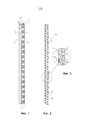
На фиг. 1 представлена, в перспективном изображении, несущая рейка.FIG. 1 is a perspective view of a carrier rail.
На фиг. 2 представлена, в перспективном изображении, накладка, пригодная для использования в комбинации с несущей рейкой по фиг. 1.FIG. 2 is a perspective view of a strip suitable for use in combination with the carrier rail of FIG. 1.
На фиг. 3 участок накладки по фиг. 2 показан в увеличенном масштабе.FIG. 3, the patch section of FIG. 2 is shown on an enlarged scale.
На фиг. 4 представлена, в перспективном изображении, накладка, прикрепленная к несущей рейке и показанная на виде с обратной стороны передней поверхности данной рейки.FIG. 4 is a perspective view of a strip attached to a carrier rail and shown from the rear side of the front surface of this rail.
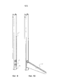
На фиг. 5 накладка показана на виде сбоку.FIG. 5, the cover is shown in a side view.
На фиг. 6 представлена несущая рейка с закрепленной на ней накладкой, причем доступ к крепежным прорезям закрыт.FIG. 6 shows a carrier rail with a pad attached to it, and access to the fastening slots is closed.
На фиг. 7 на виде по фиг. 6 представлена ситуация, когда открыт доступ к двум прорезям, расположенным одна над другой.FIG. 7 in the view of FIG. 6 shows a situation when access to two slots, located one above the other, is open.
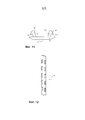
На фиг. 8 представлена несущая рейка по фиг. 7, к которой с использованием двух раскрытых прорезей прикреплена полка.FIG. 8 shows the carrier rail of FIG. 7, to which a shelf is attached using two open slots.
На фиг. 9 приведен пример, в котором открыт доступ к двум смежным парам прорезей.FIG. 9 shows an example in which two adjacent pairs of slots are accessed.
На фиг. 10 представлена несущая рейка по фиг. 9, к которой с использованием четырех раскрытых прорезей прикреплен кронштейн.FIG. 10 shows the carrier rail of FIG. 9 to which a bracket is attached using four open slots.
На фиг. 11 представлен, на виде сбоку, альтернативный вариант накладки.FIG. 11 shows, in side view, an alternative patch.
На фиг. 12 накладка по фиг. 11 показана в перспективном изображении.FIG. 12 the patch of FIG. 11 is shown in perspective view.
Осуществление изобретенияImplementation of the invention
Изобретение относится к системе хранения, в состав которой входит несущая рейка 1, проиллюстрированная на фиг. 1. Несущую рейку (несущий компонент) 1 можно изготовить из цельного удлиненного куска листового металла, в котором посредством штамповки выполнены первый ряд 3 и второй ряд 5 удлиненных прорезей 7. После этого данная рейка 1 может быть окончательно сформирована путем отгибания удлиненного участка, ориентированного по длине листа. В результате, как показано на фиг. 1, образуется несущая рейка 1 с U-образным поперечным сечением, сформированным первым отогнутым плечом 9, вторым отогнутым плечом 11 и передним участком 10 (перемычкой, имеющей переднюю поверхность 13 и соединяющей плечи 9, 11). Такие несущие рейки 1 сами по себе хорошо известны (см., в частности, ЕР 1635670 А1), причем их можно, используя, например, винты, прикреплять к стене или к другой вертикальной поверхности таким образом, чтобы плечи 9, 11 рейки упирались в стену. Кроме того, предусмотрена возможность прикрепления таких реек к комплекту ножек, стоящих на полу. Обычно несущую рейку 1 располагают вертикально. Полки, корзины, кронштейны и другие подобные объекты можно прикреплять к рейке крючками, которые вводятся в выбранные для этого прорези 7 рейки (такой способ крепления хорошо известен сам по себе). Например, можно использовать две несущих рейки и к каждой из них прикрепить кронштейн. На кронштейны может опираться полка, в результате чего хорошо известным способом образуется приемная поверхность.The invention relates to a storage system which includes a carrier rail 1 illustrated in FIG. 1. The carrier rail (carrier component) 1 can be made from a single elongated piece of sheet metal, in which the first row 3 and the
На фиг. 2 проиллюстрирована накладка 15, выполненная согласно варианту изобретения. Она может быть изготовлена из цельного куска эластомерного материала, например такого, как простой полифениленовый эфир (Polyphenylene Ether, РРЕ), статистический сополимер (рандом-сополимер) полипропилена (Polypropylene Random, PP-R) или мягкий поливинилхлорид (Polyvinyl Chloride, PVC). В общем случае, как показано на фиг. 3 в увеличенном масштабе, накладка имеет опорную поверхность 17, обеспечивающую опору на переднюю поверхность 13 несущей рейки 1. От опорной поверхности 17 выступает множество выступов 19. Как показано на фиг. 2, выступы 19 расположены попарно в виде двух рядов, образуя конфигурацию, отвечающую конфигурации расположения прорезей 7, выполненных в передней поверхности несущей рейки. В результате выступы могут быть вставлены в прорези (см. далее). Однако предусмотрена возможность некоторые выступы из данной конфигурации исключить, так что в таком варианте не каждой прорези рейки 1 соответствует ответный выступ. Как показано на фиг. 2, по длине накладки, по ее средней линии (продольной оси) проходит продольная линия 21 отрыва, представляющая собой продольный надрез.FIG. 2 illustrates a
Аналогичным образом, как наиболее наглядно показано на фиг. 3, накладка имеет поперечные линии 23 отрыва в форме надрезов, разделяющие следующие друг за другом пары 25 выступов 19. Продольная линия 21 отрыва и поперечные линии 23 отрыва облегчают удаление некоторых выступов 19 вместе с участком накладки, окружающим каждый удаляемый выступ, так что после установки накладки на несущую рейку можно открыть доступ только к требуемым прорезям рейки 1. Как наиболее наглядно показано на фиг. 3, каждый выступ 19 у своего дистального конца (т.е. у части выступа, расположенной на максимальном расстоянии от опорной поверхности 17) может быть снабжен защелкой 27. В общем случае каждый выступ 19 выполнен удлиненным вдоль опорной поверхности, т.е. в продольном направлении накладки как единого целого. Его длина может быть равна длине прорези 7 или немного короче ее, а ширина - меньше ширины прорези или равна этой ширине, что позволяет установить выступ в прорезь. Однако защелка 27, имеющаяся у дистального конца выступа, может быть шире прорези 7. Как показано, например, на фиг. 3, между каждой парой 25 выступов 19 предусмотрен зазор 29.Likewise, as most clearly shown in FIG. 3, the patch has transverse notch-shaped
На фиг. 4 проиллюстрирована, в перспективном изображении, несущая рейка 1 с установленной на нее накладкой 15, представленная на виде со стороны, обратной по отношению к передней поверхности 13. Как показано на фиг. 4, выступы введены в каждую прорезь, а защелки 27, после их продавливания через прорези, упруго расширились, удерживая накладку на месте. Установленная таким образом накладка 15 выполняет функцию гашения звука. Это означает, например, что, когда к некоторым из прорезей прикрепляют кронштейн, т.е. соединяют две детали из листового металла, возникающий в результате шум в какой-то степени гасится накладкой. В добавление к этому эффекту, посредством накладки 15 можно обеспечить наличие однородной и легко очищаемой наружной поверхности, не имеющей лишних отверстий, как это показано, в частности, на фиг. 6.FIG. 4 is a perspective view of a carrier rail 1 with a
На фиг. 5 накладка 15 проиллюстрирована на виде сбоку. Как показано на фиг. 5, предусмотрена возможность выполнить ее наружную поверхность 31 слегка выпуклой, а опорную поверхность 17, по существу, плоской, если не считать выступающих из нее выступов 19. Как показано на фиг. 5, защелка 27 у дистального конца выступа 19 может быть выполнена с первым и вторым краевыми участками 33, выступающими на некоторое расстояние в сторону опорной поверхности 17. Это означает, что, когда накладка 15 прикреплена к несущей рейке, у которой толщина листового металла больше расстояния между краевыми участками 33 и опорной поверхностью 17, передняя поверхность 13 листового металла рейки, оказавшегося между краевыми участками 33 и поверхностью 17, в определенной степени будет зажата, что уменьшит распространение какого-либо звука. Однако приемлемы также и варианты, в которых защелка просто шире, чем выступ 19 у его проксимального конца 18.FIG. 5, trim 15 is illustrated in a side view. As shown in FIG. 5, it is possible to make its
Как показано на фиг. 5, продольная линия отрыва проникает в накладку 15 на расстояние, которое меньше половины толщины накладки, хотя это расстояние можно увеличить. В любом случае данная линия отрыва облегчает удаление некоторых участков накладки. Данное удаление может быть выполнено посредством отрезания с помощью ножниц или острого ножа. Если линия отрыва выполнена достаточно глубокой, обеспечивается возможность просто оторвать требуемые участки. Как будет показано далее, накладка может быть изготовлена экструдированием эластичной полимерной полосы, которая имеет однородное поперечное сечение, показанное на фиг. 5 (на виде сбоку).As shown in FIG. 5, the longitudinal tear line penetrates the
На фиг. 6 проиллюстрирован вариант, в котором на несущую рейку 1 установлена накладка, не имеющая удаленных участков.FIG. 6 illustrates a variant in which an overlay is installed on the carrier rail 1, which does not have remote sections.
На фиг. 7 проиллюстрирован вариант, в котором, чтобы открыть доступ к соответствующим прорезям, два смежных выступа одного ряда вместе с окружающими их участками удалены посредством разрезания накладки 15 вдоль соответствующих линий отрыва. Разрезана половина каждой из двух поперечных линий отрыва, а продольная линия отрыва разрезана на участке между этими двумя поперечными линиями. Как показано на фиг. 8, это позволяет прикрепить полку 35 из листового металла, используя две прорези 7 несущей рейки, к которым открыт доступ.FIG. 7 illustrates an embodiment in which, in order to provide access to the respective slots, two adjacent protrusions of the same row, together with their surrounding regions, are removed by cutting the
На фиг. 9 проиллюстрирован другой вариант, в котором, посредством разрезания накладки 15 в двух местах вдоль поперечной линии отрыва, открыт доступ к двум смежным парам прорезей. Это позволяет прикрепить кронштейн 37, используя все четыре раскрытые прорези 7, как это показано на фиг. 10.FIG. 9, another embodiment is illustrated in which, by cutting the
На фиг. 11 проиллюстрирован, на виде сбоку, альтернативный вариант накладки 15', представленный также, в перспективном изображении, на фиг. 12. В данной накладке 15' выступы 19' выступают от опорной поверхности 17 с наклоном. У своих проксимальных концов 18 выступы могут иметь ту же конфигурацию, что и на фиг. 5. Они совмещены с прорезями 7 несущей рейки, но выступают в направлении, наклоненном от средней линии накладки 15'. В то же время, как показано на фиг. 11, их дистальные концы могут быть сформированы так, что при нажатии в сторону несущей рейки выступы 19' отгибаются внутрь. Когда каждая защелка 27 проходит в прорезь на достаточное расстояние, выступы 19' переходят скачком в исходное состояние. В прикрепленном положении выступы 19' могут немного отжиматься к боковой стороне своей прорези, что помогает отцентрировать накладку на рейке. Следует отметить, что выступы сами по себе способствуют удерживанию накладки на месте в замкнутом положении. Тем не менее, можно снабдить защелки краевыми участками 33.FIG. 11 illustrates, in a side view, an alternative patch 15 ', also shown in perspective in FIG. 12. In this strip 15 ', the projections 19' project from the
Предусмотрена возможность изготавливать накладки согласно описанным выше вариантам посредством инжекционного формования. Однако накладки длиннее 40 см потребовали бы применения относительно дорогого формовочного оборудования. Поэтому был разработан альтернативный технологический способ, согласно которому на первой операции экструдируют накладку, однородную по всей своей длине и имеющую поперечное сечение, соответствующее профилю по фиг. 5. Чтобы удалить, в частности, материал 39, показанный пунктиром на фиг. 3, на второй операции прорезают ребра поперек продольной оси накладки, формируя отдельные выступы. В случае использования продольной линии отрыва ее можно сформировать на стадии экструдирования, в то время как поперечные линии отрыва могут быть прорезаны на второй или более поздней стадии. Таким способом можно изготовить накладку любой длины.It is possible to manufacture the patches according to the above-described embodiments by injection molding. However, overlays longer than 40 cm would require relatively expensive molding equipment. Therefore, an alternative technological method has been developed, according to which, in a first step, a strip is extruded, uniform along its entire length and having a cross-section corresponding to the profile in FIG. 5. To remove, in particular, the material 39 shown in broken lines in FIG. 3, in a second step, the ribs are cut across the longitudinal axis of the pad, forming separate projections. If a longitudinal tear-off line is used, it can be formed in the extrusion step, while the transverse tear-off lines can be cut in a second or later step. In this way, you can make a patch of any length.
Приведенными примерами изобретение не ограничено. В него могут быть внесены различные изменения и модификации, не выходящие за границы прилагаемой формулы.The invention is not limited to these examples. It may be subject to various changes and modifications that do not go beyond the scope of the attached formula.
Claims (10)
Applications Claiming Priority (3)
| Application Number | Priority Date | Filing Date | Title |
|---|---|---|---|
| SE1551570-3 | 2015-12-01 | ||
| SE1551570A SE539372C2 (en) | 2015-12-01 | 2015-12-01 | A storage system comprising a cover strip for a carrier rail |
| PCT/SE2016/051192 WO2017095312A1 (en) | 2015-12-01 | 2016-11-30 | Storage system, cover strip, and method for producing a cover strip |
Publications (3)
| Publication Number | Publication Date |
|---|---|
| RU2018119537A3 RU2018119537A3 (en) | 2020-01-09 |
| RU2018119537A RU2018119537A (en) | 2020-01-09 |
| RU2733242C2 true RU2733242C2 (en) | 2020-09-30 |
Family
ID=58797421
Family Applications (1)
| Application Number | Title | Priority Date | Filing Date |
|---|---|---|---|
| RU2018119537A RU2733242C2 (en) | 2015-12-01 | 2016-11-30 | Storage system, cover plate and method of making cover plate |
Country Status (7)
| Country | Link |
|---|---|
| US (2) | US10610016B2 (en) |
| EP (1) | EP3383228B1 (en) |
| DK (1) | DK3383228T3 (en) |
| PL (1) | PL3383228T3 (en) |
| RU (1) | RU2733242C2 (en) |
| SE (1) | SE539372C2 (en) |
| WO (1) | WO2017095312A1 (en) |
Families Citing this family (13)
| Publication number | Priority date | Publication date | Assignee | Title |
|---|---|---|---|---|
| CN106049692B (en) * | 2016-07-29 | 2018-02-27 | 浙江飞屋建筑科技有限公司 | A kind of light steel house connecting structure |
| RU2764970C2 (en) | 2017-10-27 | 2022-01-24 | Элфа Интернешенел Аб | Wall-mounted configurable storage system |
| US10415873B2 (en) | 2017-12-08 | 2019-09-17 | Electrolux Home Products, Inc. | Dual asymmetrical and symmetrical architecture cantilever positioning |
| USD914406S1 (en) * | 2018-06-21 | 2021-03-30 | The Ondrasik Family Trust | Wire receiving shelf post |
| USD932656S1 (en) * | 2018-07-09 | 2021-10-05 | Shenter Enterprise Co., Ltd. | Post |
| KR20210027913A (en) * | 2019-09-03 | 2021-03-11 | 엘지전자 주식회사 | A refrigerator |
| SE543835C2 (en) | 2019-12-23 | 2021-08-10 | Elfa Int Ab | Shelf storage system comprising hang standards with screw holes at distances corresponding to desired bracket to bracket distances |
| SE544174C2 (en) | 2020-04-30 | 2022-02-22 | Elfa Int Ab | Hang standard and storage system including the hang standard |
| WO2021221555A1 (en) * | 2020-04-30 | 2021-11-04 | Elfa International Ab | Suspension system comprising a rear rail arranged with flanges at least partially extending in different directions and a hangstandard arrangable thereto |
| KR102494300B1 (en) * | 2021-01-14 | 2023-02-06 | (주)서전산업 | Horizontal bar of prefabricated angle display stand and manufacturing method thereof |
| MX2022005436A (en) * | 2021-02-05 | 2022-11-07 | Hangzhou Great Star Ind Co Ltd | Trim, vertical beam assembly and storage system. |
| SE545432C2 (en) * | 2022-01-26 | 2023-09-12 | Elfa Int Ab | Suspension system comprising a rear rail, a hang standard, an inner locking member and an outer locking member |
| US11759010B2 (en) * | 2022-01-28 | 2023-09-19 | Delta Cycle Corporation | Supportive and aesthetically pleasing adjustable shelf system |
Citations (7)
| Publication number | Priority date | Publication date | Assignee | Title |
|---|---|---|---|---|
| US3532212A (en) * | 1968-11-18 | 1970-10-06 | Streater Ind Inc | Plug buttons for vertically adjustable shelf assemblies |
| US5370249A (en) * | 1993-11-09 | 1994-12-06 | Russell-William, Ltd. | Display fixture assembly |
| US6644609B1 (en) * | 2002-09-11 | 2003-11-11 | Gene Scott | Wall mounted shelving system |
| US20050284586A1 (en) * | 2004-06-28 | 2005-12-29 | Wayne-Dalton Corp. | Breakaway track system for an overhead door |
| US20070089819A1 (en) * | 2005-09-01 | 2007-04-26 | Raymond Zenkich | Shelf Cover Apparatus |
| DE102010039533A1 (en) * | 2010-07-05 | 2012-01-05 | Bohnacker Systeme Gmbh | Covering strip for rail of shelf system, has fastening device for fastening at rail, where strip is divided into portions through predetermined breaking point passing along transverse direction of strip |
| RU126913U1 (en) * | 2012-04-18 | 2013-04-20 | Андрей Владимирович Зобнин | HIGH STRENGTH RACK RACK |
Family Cites Families (19)
| Publication number | Priority date | Publication date | Assignee | Title |
|---|---|---|---|---|
| US2261956A (en) * | 1938-02-16 | 1941-11-11 | C Steel Equipment Co Inc Ab | Demountable shelving |
| US3342095A (en) * | 1965-03-05 | 1967-09-19 | Nat Lock Co | Snap-in fastener |
| US3933102A (en) * | 1974-09-23 | 1976-01-20 | Brunette Frederick F | Display rack extension |
| US4453641A (en) * | 1980-04-01 | 1984-06-12 | Interlake, Inc. | Gravity-feed storage and delivery system |
| ZA822552B (en) * | 1981-04-22 | 1983-03-30 | Dexion Comino Int Ltd | Framework connection means |
| US4513669A (en) * | 1983-01-03 | 1985-04-30 | Lyon Metal Products, Incorporated | Shelving structure and clip used therein |
| US5004201A (en) * | 1989-07-14 | 1991-04-02 | Knape & Vogt Manufacturing Company | Interlock shelving bracket and standard cover |
| DE4013989A1 (en) * | 1990-05-01 | 1991-11-07 | Schaefer Gmbh Fritz | CARRIER DEVICE FOR INSTALLATION ON SHELVES |
| US5253835A (en) | 1992-02-18 | 1993-10-19 | Herron Iii Warren L | Shelf bracket assembly |
| US5423510A (en) * | 1993-07-28 | 1995-06-13 | Almoslino; Hans | Decorative covering for shelf brackets and standards |
| DE9409923U1 (en) * | 1994-06-22 | 1994-12-22 | Rosberg Franz | Support frame for shelves |
| US6182933B1 (en) * | 1999-05-22 | 2001-02-06 | Daniel T. Rapp | Friction-mountable hanger |
| ES2347565T3 (en) * | 2003-11-18 | 2010-11-02 | Innovation Central Pty Ltd | ELASTIC PROTECTOR TO PROTECT A STRUCTURE OF AN IMPACT. |
| US20050184415A1 (en) * | 2004-02-06 | 2005-08-25 | Masaki Ohashi | Method for producing extruded products |
| CA2504113A1 (en) * | 2005-04-08 | 2006-10-08 | Steve Vaskuthy | Box spring structure |
| US8365928B1 (en) * | 2009-06-02 | 2013-02-05 | Design Display Group, Inc. | Gondola standard cover |
| US8561953B2 (en) * | 2011-02-24 | 2013-10-22 | Thorco Industries Llc | Upright adapter for shelving systems |
| US9989206B2 (en) * | 2013-03-11 | 2018-06-05 | Inception Innovations, Llc | Architectural lighting methods and apparatus |
| US10668955B2 (en) * | 2018-07-25 | 2020-06-02 | Trim-Lok, Inc. | Fender flare for vehicles |
-
2015
- 2015-12-01 SE SE1551570A patent/SE539372C2/en unknown
-
2016
- 2016-11-30 WO PCT/SE2016/051192 patent/WO2017095312A1/en active Application Filing
- 2016-11-30 RU RU2018119537A patent/RU2733242C2/en active
- 2016-11-30 US US15/780,630 patent/US10610016B2/en active Active
- 2016-11-30 DK DK16871154.7T patent/DK3383228T3/en active
- 2016-11-30 EP EP16871154.7A patent/EP3383228B1/en active Active
- 2016-11-30 PL PL16871154T patent/PL3383228T3/en unknown
-
2020
- 2020-03-02 US US16/807,144 patent/US11044995B2/en active Active
Patent Citations (7)
| Publication number | Priority date | Publication date | Assignee | Title |
|---|---|---|---|---|
| US3532212A (en) * | 1968-11-18 | 1970-10-06 | Streater Ind Inc | Plug buttons for vertically adjustable shelf assemblies |
| US5370249A (en) * | 1993-11-09 | 1994-12-06 | Russell-William, Ltd. | Display fixture assembly |
| US6644609B1 (en) * | 2002-09-11 | 2003-11-11 | Gene Scott | Wall mounted shelving system |
| US20050284586A1 (en) * | 2004-06-28 | 2005-12-29 | Wayne-Dalton Corp. | Breakaway track system for an overhead door |
| US20070089819A1 (en) * | 2005-09-01 | 2007-04-26 | Raymond Zenkich | Shelf Cover Apparatus |
| DE102010039533A1 (en) * | 2010-07-05 | 2012-01-05 | Bohnacker Systeme Gmbh | Covering strip for rail of shelf system, has fastening device for fastening at rail, where strip is divided into portions through predetermined breaking point passing along transverse direction of strip |
| RU126913U1 (en) * | 2012-04-18 | 2013-04-20 | Андрей Владимирович Зобнин | HIGH STRENGTH RACK RACK |
Also Published As
| Publication number | Publication date |
|---|---|
| SE539372C2 (en) | 2017-08-22 |
| US10610016B2 (en) | 2020-04-07 |
| EP3383228A1 (en) | 2018-10-10 |
| US20200196757A1 (en) | 2020-06-25 |
| PL3383228T3 (en) | 2021-04-06 |
| US11044995B2 (en) | 2021-06-29 |
| WO2017095312A1 (en) | 2017-06-08 |
| EP3383228B1 (en) | 2020-09-30 |
| SE1551570A1 (en) | 2017-06-02 |
| RU2018119537A3 (en) | 2020-01-09 |
| RU2018119537A (en) | 2020-01-09 |
| EP3383228A4 (en) | 2019-08-07 |
| DK3383228T3 (en) | 2020-12-21 |
| US20180352953A1 (en) | 2018-12-13 |
Similar Documents
| Publication | Publication Date | Title |
|---|---|---|
| RU2733242C2 (en) | Storage system, cover plate and method of making cover plate | |
| US7019213B1 (en) | Cable management system | |
| US7417188B2 (en) | Cable management system | |
| RU2733364C2 (en) | Suspension system | |
| US7987799B2 (en) | Adjustable shelf | |
| US7121417B2 (en) | Fastening device | |
| BE1021263B1 (en) | SUPPORT BRACKET FOR SUPPORTING A SLATE OF A GARDEN WIRE PANEL | |
| US20140197121A1 (en) | Width-adjustable storage module for cabinets | |
| RU2001121482A (en) | CABLE ACCOMMODATION SYSTEM, INSTALLATION AND CABLE INSTALLATION | |
| US11064808B2 (en) | Rack system | |
| FI122353B (en) | Lockable Shelf Bracket | |
| RU2008123851A (en) | STORAGE DEVICE FOR DISHWASHING MACHINE | |
| US9603468B2 (en) | Holding device for a bracket in a storage system | |
| US20170215579A1 (en) | Shelving System | |
| CA2942201A1 (en) | Modular hooking device for a cloth for a tensioned false ceiling | |
| KR20020042679A (en) | Bracket system for shelving | |
| US20040020884A1 (en) | System for detachable suspension of shelves, drawers or the like | |
| AU2017246237A1 (en) | Basket | |
| WO2004112541A1 (en) | A system for storing objects | |
| EP1547503A1 (en) | Sheet edge support | |
| KR200484181Y1 (en) | Anti-sound and vibration-absobing steel grating | |
| KR101511123B1 (en) | Clothes rack on closet | |
| JP5897586B2 (en) | Transport rail for drawer base | |
| RU2231277C1 (en) | Shelf | |
| KR101475485B1 (en) | Cable lead-out device installed at tray side |