RU2728103C2 - Aerosol-generating system comprising a variable air inlet - Google Patents
Aerosol-generating system comprising a variable air inlet Download PDFInfo
- Publication number
- RU2728103C2 RU2728103C2 RU2018126636A RU2018126636A RU2728103C2 RU 2728103 C2 RU2728103 C2 RU 2728103C2 RU 2018126636 A RU2018126636 A RU 2018126636A RU 2018126636 A RU2018126636 A RU 2018126636A RU 2728103 C2 RU2728103 C2 RU 2728103C2
- Authority
- RU
- Russia
- Prior art keywords
- air inlet
- mouthpiece
- cartridge
- aerosol generating
- generating system
- Prior art date
Links
Images
Classifications
-
- A—HUMAN NECESSITIES
- A24—TOBACCO; CIGARS; CIGARETTES; SIMULATED SMOKING DEVICES; SMOKERS' REQUISITES
- A24F—SMOKERS' REQUISITES; MATCH BOXES; SIMULATED SMOKING DEVICES
- A24F40/00—Electrically operated smoking devices; Component parts thereof; Manufacture thereof; Maintenance or testing thereof; Charging means specially adapted therefor
- A24F40/30—Devices using two or more structurally separated inhalable precursors, e.g. using two liquid precursors in two cartridges
-
- A—HUMAN NECESSITIES
- A24—TOBACCO; CIGARS; CIGARETTES; SIMULATED SMOKING DEVICES; SMOKERS' REQUISITES
- A24F—SMOKERS' REQUISITES; MATCH BOXES; SIMULATED SMOKING DEVICES
- A24F47/00—Smokers' requisites not otherwise provided for
-
- A—HUMAN NECESSITIES
- A24—TOBACCO; CIGARS; CIGARETTES; SIMULATED SMOKING DEVICES; SMOKERS' REQUISITES
- A24B—MANUFACTURE OR PREPARATION OF TOBACCO FOR SMOKING OR CHEWING; TOBACCO; SNUFF
- A24B15/00—Chemical features or treatment of tobacco; Tobacco substitutes, e.g. in liquid form
- A24B15/10—Chemical features of tobacco products or tobacco substitutes
- A24B15/16—Chemical features of tobacco products or tobacco substitutes of tobacco substitutes
- A24B15/167—Chemical features of tobacco products or tobacco substitutes of tobacco substitutes in liquid or vaporisable form, e.g. liquid compositions for electronic cigarettes
-
- A—HUMAN NECESSITIES
- A24—TOBACCO; CIGARS; CIGARETTES; SIMULATED SMOKING DEVICES; SMOKERS' REQUISITES
- A24D—CIGARS; CIGARETTES; TOBACCO SMOKE FILTERS; MOUTHPIECES OF CIGARS OR CIGARETTES; MANUFACTURE OF TOBACCO SMOKE FILTERS OR MOUTHPIECES
- A24D1/00—Cigars; Cigarettes
- A24D1/002—Cigars; Cigarettes with additives, e.g. for flavouring
-
- A—HUMAN NECESSITIES
- A24—TOBACCO; CIGARS; CIGARETTES; SIMULATED SMOKING DEVICES; SMOKERS' REQUISITES
- A24F—SMOKERS' REQUISITES; MATCH BOXES; SIMULATED SMOKING DEVICES
- A24F40/00—Electrically operated smoking devices; Component parts thereof; Manufacture thereof; Maintenance or testing thereof; Charging means specially adapted therefor
- A24F40/10—Devices using liquid inhalable precursors
-
- A—HUMAN NECESSITIES
- A24—TOBACCO; CIGARS; CIGARETTES; SIMULATED SMOKING DEVICES; SMOKERS' REQUISITES
- A24F—SMOKERS' REQUISITES; MATCH BOXES; SIMULATED SMOKING DEVICES
- A24F40/00—Electrically operated smoking devices; Component parts thereof; Manufacture thereof; Maintenance or testing thereof; Charging means specially adapted therefor
- A24F40/40—Constructional details, e.g. connection of cartridges and battery parts
- A24F40/42—Cartridges or containers for inhalable precursors
-
- A—HUMAN NECESSITIES
- A24—TOBACCO; CIGARS; CIGARETTES; SIMULATED SMOKING DEVICES; SMOKERS' REQUISITES
- A24F—SMOKERS' REQUISITES; MATCH BOXES; SIMULATED SMOKING DEVICES
- A24F40/00—Electrically operated smoking devices; Component parts thereof; Manufacture thereof; Maintenance or testing thereof; Charging means specially adapted therefor
- A24F40/40—Constructional details, e.g. connection of cartridges and battery parts
- A24F40/46—Shape or structure of electric heating means
- A24F40/465—Shape or structure of electric heating means specially adapted for induction heating
-
- A—HUMAN NECESSITIES
- A24—TOBACCO; CIGARS; CIGARETTES; SIMULATED SMOKING DEVICES; SMOKERS' REQUISITES
- A24F—SMOKERS' REQUISITES; MATCH BOXES; SIMULATED SMOKING DEVICES
- A24F40/00—Electrically operated smoking devices; Component parts thereof; Manufacture thereof; Maintenance or testing thereof; Charging means specially adapted therefor
- A24F40/40—Constructional details, e.g. connection of cartridges and battery parts
- A24F40/48—Fluid transfer means, e.g. pumps
- A24F40/485—Valves; Apertures
-
- A—HUMAN NECESSITIES
- A24—TOBACCO; CIGARS; CIGARETTES; SIMULATED SMOKING DEVICES; SMOKERS' REQUISITES
- A24F—SMOKERS' REQUISITES; MATCH BOXES; SIMULATED SMOKING DEVICES
- A24F7/00—Mouthpieces for pipes; Mouthpieces for cigar or cigarette holders
- A24F7/02—Mouthpieces for pipes; Mouthpieces for cigar or cigarette holders with detachable connecting members
Landscapes
- Chemical & Material Sciences (AREA)
- Chemical Kinetics & Catalysis (AREA)
- General Chemical & Material Sciences (AREA)
- Medicinal Preparation (AREA)
- Nozzles (AREA)
- Containers And Packaging Bodies Having A Special Means To Remove Contents (AREA)
Abstract
Description
Настоящее изобретение относится к системе, генерирующей аэрозоль, содержащей картридж и мундштук, при этом мундштук имеет изменяемое впускное отверстие для воздуха. Настоящее изобретение находит конкретное применение в качестве системы, генерирующей аэрозоль, содержащей источник никотина и источник кислоты для генерирования аэрозоля, содержащего частицы соли никотина.The present invention relates to an aerosol generating system comprising a cartridge and a mouthpiece, the mouthpiece having a variable air inlet. The present invention finds particular application as an aerosol generating system comprising a nicotine source and an acid source for generating an aerosol containing nicotine salt particles.
Известны устройства для доставки никотина пользователю, содержащие источник никотина и источник летучего соединения, ускоряющего доставку. Например, в WO 2008/121610 A1 раскрыты устройства, в которых никотин и летучая кислота, такая как пировиноградная кислота, вступают в реакцию друг с другом в газовой фазе с образованием аэрозоля из частиц соли никотина, который вдыхается пользователем.Devices for delivering nicotine to a user are known comprising a nicotine source and a volatile delivery accelerating compound source. For example, WO 2008/121610 A1 discloses devices in which nicotine and a volatile acid, such as pyruvic acid, react with each other in the gas phase to form an aerosol of nicotine salt particles that is inhaled by the user.
При использовании системы, генерирующей аэрозоль, описанного в WO 2008/121610 A1 типа, впечатление пользователя может зависеть от реакции стехиометрии между никотином и источником соединения, ускоряющего доставку. Впечатление пользователя может зависеть от общей доставки частиц соли никотина с каждой затяжкой. Впечатление пользователя может зависеть от сопротивления втягиванию (RTD) через систему, генерирующую аэрозоль.When using an aerosol generating system of the type described in WO 2008/121610 A1, the user experience may depend on the stoichiometric response between nicotine and the source of the delivery accelerating compound. The user experience may be affected by the overall delivery of nicotine salt particles with each puff. The user experience may be influenced by the retract resistance (RTD) through the aerosol generating system.
Желательно предоставить систему, генерирующую аэрозоль, которая обеспечивает улучшенные возможности предугадывания или регулирования стехиометрии реакции, общей доставки частиц соли никотина или RTD через систему, генерирующую аэрозоль.It is desirable to provide an aerosol generating system that provides improved predictability or control of reaction stoichiometry, overall delivery of nicotine salt particles or RTDs through the aerosol generating system.
Согласно настоящему изобретению предложена система, генерирующая аэрозоль, содержащая картридж, при этом картридж содержит первое отделение, содержащее источник никотина, и второе отделение, содержащее источник кислоты. Первое отделение имеет первое впускное отверстие для воздуха и первое выпускное отверстие для воздуха, а второе отделение имеет второе впускное отверстие для воздуха и второе выпускное отверстие для воздуха. Система, генерирующая аэрозоль, дополнительно содержит мундштук, выполненный с возможностью зацепления с картриджем для образования камеры, находящейся в сообщении по текучей среде с первым выпускным отверстием для воздуха и вторым выпускным отверстием для воздуха. Мундштук содержит третье впускное отверстие для воздуха, находящееся в сообщении по текучей среде с камерой, и третье выпускное отверстие для воздуха, находящееся в сообщении по текучей среде с камерой, при этом третье впускное отверстие для воздуха определяет площадь поперечного сечения потока, и при этом мундштук выполнен таким образом, что площадь сечения потока через третье впускное отверстие для воздуха является изменяемой.The present invention provides an aerosol generating system comprising a cartridge, wherein the cartridge comprises a first compartment containing a nicotine source and a second compartment containing an acid source. The first compartment has a first air inlet and a first air outlet, and the second compartment has a second air inlet and a second air outlet. The aerosol generating system further comprises a mouthpiece adapted to engage the cartridge to form a chamber in fluid communication with the first air outlet and the second air outlet. The mouthpiece comprises a third air inlet in fluid communication with the chamber and a third air outlet in fluid communication with the chamber, the third air inlet defining the cross-sectional area of the flow, and the mouthpiece is configured such that the cross-sectional area of the flow through the third air inlet is variable.
Термин «впускное отверстие для воздуха», используемый в данном документе применительно к изобретению, используется для описания одного или нескольких отверстий, через которые воздух может втягиваться в компонент или часть компонента системы, генерирующей аэрозоль.The term "air inlet" as used herein in relation to the invention is used to describe one or more openings through which air can be drawn into a component or part of a component of an aerosol generating system.
Термин «выпускное отверстие для воздуха», используемый в данном документе применительно к изобретению, используется для описания одного или нескольких отверстий, через которые воздух может выпускаться из компонента или части компонента системы, генерирующей аэрозоль.The term "air outlet" as used herein in relation to the invention is used to describe one or more openings through which air can be discharged from a component or part of a component of an aerosol generating system.
Термин «площадь сечения потока», используемый в данном документе применительно к изобретению, используется для описания общей площади впускного отверстия для воздуха или выпускного отверстия для воздуха, через которые воздух проходит во время использования. В вариантах осуществления, в которых впускное отверстие для воздуха или выпускное отверстие для воздуха представляет собой множество отверстий, площадь сечения потока впускного отверстия для воздуха или выпускного отверстия для воздуха представляет собой общую площадь сечения потока множества отверстий. В вариантах осуществления, где площадь поперечного сечения впускного отверстия для воздуха или выпускного отверстия для воздуха меняется в направлении потока воздуха, площадь сечения потока впускного отверстия для воздуха или выпускного отверстия для воздуха представляет собой минимальную площадь поперечного сечения в направлении потока воздуха. В системах, генерирующих аэрозоль, согласно настоящему изобретению площадь сечения потока третьего впускного отверстия для воздуха является изменяемой. То есть, система, генерирующая аэрозоль, может преобразовываться в несколько конфигураций, при этом в разных конфигурациях площадь сечения потока третьего впускного отверстия для воздуха разная. В заданной конфигурации системы, генерирующей аэрозоль, площадь сечения потока третьего впускного отверстия для воздуха представляет собой минимальную площадь поперечного сечения третьего впускного отверстия для воздуха, в направлении потока воздуха, для указанной конфигурации системы, генерирующей аэрозоль. По меньшей мере одна конфигурация может определять максимальную площадь сечения потока третьего впускного отверстия для воздуха. По меньшей мере одна конфигурация может определять минимальную площадь сечения потока третьего впускного отверстия для воздуха. Остальные конфигурации могут определять одну или несколько площадей сечения потока третьего впускного отверстия для воздуха, находящихся между максимальной площадью сечения потока третьего впускного отверстия для воздуха и минимальной площадью сечения потока третьего впускного отверстия для воздуха.The term “flow area” as used herein in connection with the invention is used to describe the total area of an air inlet or air outlet through which air passes during use. In embodiments in which the air inlet or air outlet is a plurality of holes, the flow area of the air inlet or air outlet is the total flow area of the plurality of holes. In embodiments where the cross-sectional area of the air inlet or air outlet changes in the air flow direction, the flow area of the air inlet or air outlet is the minimum cross-sectional area in the air flow direction. In aerosol generating systems according to the present invention, the flow area of the third air inlet is variable. That is, the aerosol generating system can be converted into several configurations, with different configurations having different flow cross-sectional areas of the third air inlet. In a given configuration of the aerosol generating system, the flow area of the third air inlet is the minimum cross-sectional area of the third air inlet, in the air flow direction, for the specified configuration of the aerosol generating system. At least one configuration can define the maximum flow area of the third air inlet. The at least one configuration can define a minimum flow area of the third air inlet. The remaining configurations may define one or more flow areas of the third air inlet between the maximum flow area of the third air inlet and the minimum flow area of the third air inlet.
Преимущественно за счет предоставления источника никотина и источника кислоты в отдельных первом и втором отделениях с отдельными впускными отверстиями для воздуха и отдельными выпускными отверстиями для воздуха, системы, генерирующие аэрозоль, согласно настоящему изобретению предпочтительно улучшают регулирование стехиометрии реакции никотина и кислоты. Например, стехиометрию реакции можно регулировать и уравновешивать, изменяя объемный поток воздуха через первое отделение картриджа по отношению к объемному потоку воздуха через второе отделение картриджа.Advantageously by providing a nicotine source and an acid source in separate first and second compartments with separate air inlets and separate air outlets, the aerosol generating systems of the present invention preferably improve stoichiometry control of the nicotine and acid reaction. For example, the stoichiometry of the reaction can be adjusted and balanced by varying the volumetric airflow through the first compartment of the cartridge relative to the volumetric airflow through the second compartment of the cartridge.
Преимущественно за счет предоставления мундштука, образующего камеру, находящуюся в сообщении по текучей среде с первым выпускным отверстием для воздуха и вторым выпускным отверстием для воздуха, и содержащего третье впускное отверстие для воздуха, находящееся в сообщении по текучей среде с камерой и имеющее изменяющуюся площадь сечения потока, системы, генерирующие аэрозоль, согласно настоящему изобретению способствуют регулированию общей доставки частиц соли никотина на единицу объема потока воздуха через третье выпускное отверстие для воздуха. То есть, изменение площади сечения потока третьего впускного отверстия для воздуха регулирует общую доставку частиц соли никотина на единицу объема потока воздуха через третье выпускное отверстие для воздуха. За счет увеличения площади сечения потока третьего впускного отверстия для воздуха увеличивается объемный поток воздуха через третье впускное отверстие для воздуха по сравнению с общим объемным потоком воздуха через первое и второе выпускные отверстия для воздуха, что снижает общую доставку частиц соли никотина на единицу объема потока воздуха через третье выпускное отверстие для воздуха. За счет уменьшения площади сечения потока третьего впускного отверстия для воздуха уменьшается объемный поток воздуха через третье впускное отверстие для воздуха по сравнению с общим объемным потоком воздуха через первое и второе выпускные отверстия для воздуха, что увеличивает общую доставку частиц соли никотина на единицу объема потока воздуха через третье выпускное отверстие для воздуха.Advantageously by providing a mouthpiece defining a chamber in fluid communication with a first air outlet and a second air outlet, and comprising a third air inlet in fluid communication with the chamber and having a variable flow area aerosol generating systems of the present invention help to control the overall delivery of nicotine salt particles per unit volume of air flow through the third air outlet. That is, changing the flow area of the third air inlet controls the overall delivery of nicotine salt particles per unit volume of air flow through the third air outlet. By increasing the flow area of the third air inlet, the volumetric airflow through the third air inlet is increased compared to the total volumetric airflow through the first and second air outlets, which reduces the overall delivery of nicotine salt particles per unit volume of airflow through third air outlet. By reducing the flow area of the third air inlet, the volumetric airflow through the third air inlet is reduced compared to the total volumetric airflow through the first and second air outlets, which increases the overall delivery of nicotine salt particles per unit volume of airflow through third air outlet.
Преимущественно за счет предоставления мундштука, содержащего третье впускное отверстие для воздуха, имеющее изменяющуюся площадь сечения потока, может также обеспечиваться регулирование пользователем RTD через системы, генерирующие аэрозоль, согласно настоящему изобретению. За счет увеличения площади сечения потока третьего впускного отверстия для воздуха может снижаться RTD системы, генерирующей аэрозоль. За счет уменьшения площади сечения потока третьего впускного отверстия для воздуха может увеличиваться RTD системы, генерирующей аэрозоль.Advantageously, by providing a mouthpiece comprising a third air inlet having a variable flow area, user control of the RTD through the aerosol generating systems of the present invention can also be achieved. By increasing the flow area of the third air inlet, the RTD of the aerosol generating system can be reduced. By reducing the flow area of the third air inlet, the RTD of the aerosol generating system can be increased.
Предпочтительно каждое из первого впускного отверстия для воздуха, первого выпускного отверстия для воздуха, второго впускного отверстия для воздуха и второго выпускного отверстия для воздуха образовано одним или несколькими отверстиями. Отношение объемного потока воздуха через первое отделение к объемному потоку воздуха через второе отделение может регулироваться за счет изменения одного или нескольких из количества, размеров и местоположения отверстий, образующих по меньшей мере одно из первого впускного отверстия для воздуха, первого выпускного отверстия для воздуха, второго впускного отверстия для воздуха и второго выпускного отверстия для воздуха. Такие изменения по отношению к количеству, размерам и местоположению отверстий могут быть определены во время изготовления картриджа для обеспечения необходимого отношения объемного потока воздуха через первое отделение к объемному потоку воздуха через второе отделение с обеспечением необходимой стехиометрии реакции между никотином и кислотой.Preferably, each of the first air inlet, the first air outlet, the second air inlet, and the second air outlet is formed by one or more openings. The ratio of the volumetric airflow through the first compartment to the volumetric airflow through the second compartment can be adjusted by varying one or more of the number, size and location of the openings forming at least one of the first air inlet, the first air outlet, the second inlet. air holes and a second air outlet. Such variations with respect to the number, size and location of the holes can be determined during manufacture of the cartridge to provide the desired ratio of the volumetric air flow through the first compartment to the volumetric airflow through the second compartment, providing the necessary stoichiometry of the reaction between nicotine and acid.
Предпочтительно мундштук содержит первую часть мундштука и вторую часть мундштука, выполненную с возможностью перемещения по отношению к первой части мундштука, при этом относительное перемещение между первой частью мундштука и второй частью мундштука изменяет площадь сечения потока через третье впускное отверстие для воздуха. Первая часть мундштука может быть зафиксирована по отношению к картриджу. Первая часть мундштука может быть образована цельной по меньшей мере с частью картриджа. Первая часть мундштука может содержать трубчатую часть, проходящую от расположенного ниже по потоку конца картриджа.Preferably, the mouthpiece comprises a first mouthpiece portion and a second mouthpiece portion movable with respect to the first mouthpiece portion, the relative movement between the first mouthpiece portion and the second mouthpiece portion changing the flow area through the third air inlet. The first part of the mouthpiece can be fixed in relation to the cartridge. The first portion of the mouthpiece may be formed in one piece with at least a portion of the cartridge. The first mouthpiece portion may include a tubular portion extending from the downstream end of the cartridge.
Вторая часть мундштука может быть выполнена с возможностью скольжения по отношению к первой части мундштука. Вторая часть мундштука может быть выполнена с возможностью поворота по отношению к первой части мундштука. Вторая часть мундштука может быть выполнена для перемещения по спирали по отношению к первой части мундштука.The second part of the mouthpiece may be slidable with respect to the first part of the mouthpiece. The second part of the mouthpiece may be rotatable with respect to the first part of the mouthpiece. The second part of the mouthpiece can be configured to move in a spiral with respect to the first part of the mouthpiece.
Третье впускное отверстие для воздуха может быть образовано одним или несколькими отверстиями. В первой части мундштука может быть предусмотрено одно или несколько отверстий. Во второй части мундштука может быть предусмотрено одно или несколько отверстий. Одно или несколько отверстий могут содержать одно или несколько отверстий в первой части мундштука и одно или несколько отверстий во второй части мундштука. Предпочтительно вторая часть мундштука выполнена с возможностью перемещения по отношению к первой части мундштука между первым положением, в котором одно или несколько отверстий не заблокированы, и вторым положением, в котором по меньшей мере одно или несколько отверстий заблокированы. Когда вторая часть мундштука находится во втором положении, одно или несколько отверстий могут быть только частично заблокированы. Вторая часть мундштука может быть выполнена с возможностью перемещения по отношению к первой части мундштука в третье положение, в котором одно или несколько отверстий полностью заблокированы.The third air inlet can be formed by one or more openings. One or more holes may be provided in the first part of the mouthpiece. One or more holes can be provided in the second part of the mouthpiece. One or more openings may comprise one or more openings in the first part of the mouthpiece and one or more openings in the second part of the mouthpiece. Preferably, the second part of the mouthpiece is movable with respect to the first part of the mouthpiece between a first position in which one or more holes are not blocked and a second position in which at least one or more holes are blocked. When the second part of the mouthpiece is in the second position, one or more of the holes may only be partially blocked. The second part of the mouthpiece may be movable with respect to the first part of the mouthpiece to a third position in which one or more holes are completely blocked.
Выражение «не заблокированный», используемое в данном документе применительно к изобретению, означает, что отверстие, образующее по меньшей мере часть впускного отверстия для воздуха или выпускного отверстия для воздуха, не перекрыто, таким образом воздух может свободно проходить через всю область отверстия.The expression "not blocked" as used herein in relation to the invention means that the opening forming at least a portion of the air inlet or air outlet is not blocked, so that air can freely flow through the entire region of the opening.
Выражение «заблокированный», используемое в данном документе применительно к изобретению, означает, что отверстие, образующее по меньшей мере часть впускного отверстия для воздуха или выпускного отверстия для воздуха, перекрыто, таким образом поток воздуха через отверстие по существу предотвращен. Отверстие может быть частично заблокировано, таким образом воздух может проходить только через часть отверстия, которое не заблокировано.The expression "blocked" as used herein in relation to the invention means that the opening forming at least a portion of the air inlet or air outlet is closed so that air flow through the opening is substantially prevented. The hole can be partially blocked, so air can only pass through the part of the hole that is not blocked.
Третье впускное отверстие для воздуха может быть образовано множеством отверстий. Когда вторая часть мундштука находится в первом положении, предпочтительно все отверстия, образующие третье впускное отверстие для воздуха, не заблокированы. Когда вторая часть мундштука находится во втором положении, каждое из отверстий, образующих третье впускное отверстие для воздуха, может быть только частично заблокировано. Когда вторая часть мундштука находится втором положении, некоторые из отверстий, образующих третье впускное отверстие для воздуха, могут быть не заблокированы, а остальные отверстия, образующие третье впускное отверстие для воздуха, могут быть полностью заблокированы. Когда вторая часть мундштука находится во втором положении, все отверстия, образующие третье впускное отверстие для воздуха, могут быть полностью заблокированы.The third air inlet may be formed by a plurality of openings. When the second part of the mouthpiece is in the first position, preferably all openings forming the third air inlet are not blocked. When the second part of the mouthpiece is in the second position, each of the openings forming the third air inlet can only be partially blocked. When the second part of the mouthpiece is in the second position, some of the holes forming the third air inlet may not be blocked, and the rest of the holes forming the third air inlet may be completely blocked. When the second part of the mouthpiece is in the second position, all openings forming the third air inlet can be completely blocked.
В тех вариантах осуществления, в которых третье впускное отверстие для воздуха образовано множеством отверстий и вторая часть мундштука выполнена с возможностью перемещения в третье положение по отношению к первой части мундштука, все отверстия, образующие третье впускное отверстие для воздуха, могут быть полностью заблокированы, когда вторая часть мундштука находится в третьем положении.In embodiments in which the third air inlet is formed by a plurality of holes and the second mouthpiece portion is movable to a third position with respect to the first mouthpiece portion, all of the openings forming the third air inlet can be completely blocked when the second part of the mouthpiece is in the third position.
В любом из вариантов осуществления, описанных выше, максимальная площадь сечения потока третьего впускного отверстия для воздуха предпочтительно составляет от приблизительно 1,5 квадратных миллиметров до приблизительно 2 квадратных миллиметров. В вариантах осуществления, в которых мундштук содержит первую часть мундштука и вторую часть мундштука, выполненную с возможностью перемещения по отношению к первой части мундштука между первым положением и вторым положением, обеспечена предпочтительно максимальная площадь сечения потока третьего впускного отверстия для воздуха, когда вторая часть мундштука находится в первом положении.In any of the embodiments described above, the maximum flow area of the third air inlet is preferably from about 1.5 square millimeters to about 2 square millimeters. In embodiments in which the mouthpiece comprises a first mouthpiece portion and a second mouthpiece portion movable relative to the first mouthpiece portion between the first position and the second position, preferably the maximum flow area of the third air inlet is provided when the second mouthpiece portion is located in the first position.
Третье впускное отверстие для воздуха может быть образовано из множества отверстий. В таких вариантах осуществления общая максимальная площадь сечения потока через отверстия, образующие третье впускное отверстие для воздуха, предпочтительно составляет от приблизительно 1,5 квадратных миллиметров до приблизительно 2 квадратных миллиметров. Отверстия, образующие третье впускное отверстие для воздуха, могут иметь одну и ту же максимальную площадь сечения потока, таким образом общая максимальная площадь сечения потока третьего впускного отверстия для воздуха разделяется в равной степени между отверстиями, образующими третье впускное отверстие для воздуха. Отверстия, образующие третье впускное отверстие для воздуха, могут иметь разные максимальные площади сечения потока, таким образом общая максимальная площадь сечения потока третьего впускного отверстия для воздуха разделяется в неравной степени между отверстиями, образующими третье впускное отверстие для воздуха. В вариантах осуществления, в которых мундштук содержит первую часть мундштука и вторую часть мундштука, выполненную с возможностью перемещения по отношению к первой части мундштука между первым положением и вторым положением, обеспечена предпочтительно максимальная площадь сечения потока третьего впускного отверстия для воздуха, когда вторая часть мундштука находится в первом положении и все из отверстий, образующих третье впускное отверстие для воздуха, не заблокированы.The third air inlet may be formed from a plurality of holes. In such embodiments, the total maximum flow area through the openings defining the third air inlet is preferably from about 1.5 square millimeters to about 2 square millimeters. The openings forming the third air inlet may have the same maximum flow area, so the total maximum flow area of the third air inlet is divided equally between the openings forming the third air inlet. The openings forming the third air inlet may have different maximum flow areas, so that the total maximum flow area of the third air inlet is unevenly divided between the openings forming the third air inlet. In embodiments in which the mouthpiece comprises a first mouthpiece portion and a second mouthpiece portion movable relative to the first mouthpiece portion between the first position and the second position, preferably the maximum flow area of the third air inlet is provided when the second mouthpiece portion is located in the first position and all of the holes forming the third air inlet are not blocked.
В любом из вариантов осуществления, описанном выше, минимальная площадь сечения потока третьего впускного отверстия для воздуха составляет предпочтительно менее чем приблизительно 0,6 квадратных миллиметров. Минимальная площадь сечения потока третьего впускного отверстия для воздуха может быть равна приблизительно нулю. То есть, минимальная площадь сечения потока третьего впускного отверстия для воздуха может соответствовать полной блокировке третьего впускного отверстия для воздуха. В вариантах осуществления, в которых мундштук содержит первую часть мундштука и вторую часть мундштука, выполненную с возможностью перемещения по отношению к первой части мундштука между первым положением и вторым положением, может быть обеспечена минимальная площадь сечения потока третьего впускного отверстия для воздуха, когда вторая часть мундштука находится во втором положении. В тех вариантах осуществления, в которых вторая часть мундштука выполнена с возможностью перемещения в третье положение, может быть обеспечена минимальная площадь сечения потока третьего впускного отверстия для воздуха, когда вторая часть мундштука находится в третьем положении.In any of the embodiments described above, the minimum flow area of the third air inlet is preferably less than about 0.6 square millimeters. The minimum flow area of the third air inlet can be approximately zero. That is, the minimum flow area of the third air inlet can correspond to the complete blocking of the third air inlet. In embodiments in which the mouthpiece comprises a first mouthpiece portion and a second mouthpiece portion movable relative to the first mouthpiece portion between the first position and the second position, a minimum flow area of the third air inlet may be provided when the second mouthpiece portion is in the second position. In embodiments in which the second mouthpiece portion is movable to a third position, a minimum flow area of the third air inlet can be provided when the second mouthpiece portion is in the third position.
Третье впускное отверстие для воздуха может быть образовано из множества отверстий. В таких вариантах осуществления общая минимальная площадь сечения потока через отверстия, образующие третье впускное отверстие для воздуха, составляет предпочтительно менее чем приблизительно 0,6 квадратных миллиметров. Общая минимальная площадь сечения потока через отверстия, образующие третье впускное отверстие для воздуха, может быть равна приблизительно нулю. То есть, минимальная площадь сечения потока третьего впускного отверстия для воздуха может соответствовать полной блокировке отверстий, образующих третье впускное отверстие для воздуха. В вариантах осуществления, в которых мундштук содержит первую часть мундштука и вторую часть мундштука, выполненную с возможностью перемещения по отношению к первой части мундштука между первым положением и вторым положением, может быть обеспечена минимальная площадь сечения потока третьего впускного отверстия для воздуха, когда вторая часть мундштука находится во втором положении и по меньшей мере некоторые из отверстий, образующих третье впускное отверстие для воздуха, по меньшей мере частично заблокированы. В тех вариантах осуществления, в которых вторая часть мундштука выполнена с возможностью перемещения в третье положение, может быть обеспечена минимальная площадь сечения потока третьего впускного отверстия для воздуха, когда вторая часть мундштука находится в третьем положении.The third air inlet may be formed from a plurality of holes. In such embodiments, the total minimum flow area through the openings defining the third air inlet is preferably less than about 0.6 square millimeters. The total minimum flow area through the holes forming the third air inlet may be approximately zero. That is, the minimum flow area of the third air inlet can correspond to complete blocking of the openings forming the third air inlet. In embodiments in which the mouthpiece comprises a first mouthpiece portion and a second mouthpiece portion movable relative to the first mouthpiece portion between the first position and the second position, a minimum flow area of the third air inlet may be provided when the second mouthpiece portion is in a second position and at least some of the openings forming the third air inlet are at least partially blocked. In embodiments in which the second mouthpiece portion is movable to a third position, a minimum flow area of the third air inlet can be provided when the second mouthpiece portion is in the third position.
В любом из вариантов осуществления, описанном выше, третье впускное отверстие для воздуха может быть образовано из одного или нескольких отверстий. Предпочтительно общее количество отверстий, образующих третье впускное отверстие для воздуха, составляет от 2 до 10. В некоторых вариантах осуществления по меньшей мере часть мундштука имеет по существу круглую форму поперечного сечения, вокруг которой предусмотрены отверстия, образующие третье впускное отверстие для воздуха. Предпочтительно отверстия, образующие третье впускное отверстие для воздуха, разнесены на одинаковое расстояние вокруг мундштука.In any of the embodiments described above, the third air inlet may be formed from one or more openings. Preferably, the total number of holes forming the third air inlet is 2 to 10. In some embodiments, at least a portion of the mouthpiece has a substantially circular cross-sectional shape around which holes are provided to define the third air inlet. Preferably, the openings defining the third air inlet are equally spaced around the mouthpiece.
В вариантах осуществления, в которых третье впускное отверстие для воздуха образовано из одного или нескольких отверстий, каждое отверстие может иметь любую подходящую форму поперечного сечения. Например, форма поперечного сечения каждого отверстия может быть квадратной, прямоугольной, круглой или эллиптической. Предпочтительно каждое отверстие имеет по существу круглую форму поперечного сечения. Предпочтительно диаметр каждого отверстия составляет от приблизительно 0,4 миллиметра до приблизительно 0,6 миллиметра.In embodiments in which the third air inlet is formed from one or more openings, each opening may have any suitable cross-sectional shape. For example, the cross-sectional shape of each hole can be square, rectangular, circular, or elliptical. Preferably, each opening has a substantially circular cross-sectional shape. Preferably, the diameter of each hole is from about 0.4 millimeters to about 0.6 millimeters.
В вариантах осуществления, в которых третье впускное отверстие для воздуха образовано из одного или нескольких отверстий, одно или несколько отверстий могут быть удлиненными. В вариантах осуществления, в которых мундштук содержит первую часть мундштука и вторую часть мундштука, выполненную с возможностью перемещения по отношению к первой части мундштука, предпочтительно длина каждого удлиненного отверстия проходит по существу в направлении относительного перемещения между первой частью мундштука и второй частью мундштука. Преимущественно за счет образования третьего впускного отверстия для воздуха из одного или нескольких удлиненных отверстий, обеспечивается постоянное изменение площади сечения потока через третье впускное отверстие для воздуха, поскольку одно или несколько удлиненных отверстий постепенно блокируются или разблокируются. Например, в вариантах осуществления, в которых мундштук содержит первую часть мундштука и вторую часть мундштука, выполненную с возможностью перемещения по отношению к первой части мундштука, площадь сечения потока одного или нескольких удлиненных отверстий может постоянно изменяться, поскольку вторая часть мундштука перемещается относительно первой части мундштука.In embodiments in which the third air inlet is formed from one or more openings, the one or more openings may be elongated. In embodiments in which the mouthpiece comprises a first mouthpiece portion and a second mouthpiece portion movable relative to the first mouthpiece portion, preferably the length of each elongated opening extends substantially in the direction of relative movement between the first mouthpiece portion and the second mouthpiece portion. Advantageously, by forming a third air inlet from one or more of the elongated openings, a constant change in the cross-sectional area of the flow through the third air inlet is achieved as one or more of the elongated openings are gradually blocked or unlocked. For example, in embodiments in which the mouthpiece comprises a first mouthpiece portion and a second mouthpiece portion movable relative to the first mouthpiece portion, the flow area of one or more elongated openings may constantly change as the second mouthpiece portion moves relative to the first mouthpiece portion. ...
Каждое из одного или нескольких удлиненных отверстий может иметь любую подходящую форму поперечного сечения. Например, форма поперечного сечения каждого удлиненного отверстия может быть по существу прямоугольной или по существу эллиптической.Each of the one or more elongated holes can have any suitable cross-sectional shape. For example, the cross-sectional shape of each elongated hole may be substantially rectangular or substantially elliptical.
Третье впускное отверстие для воздуха может быть образовано из одного удлиненного отверстия. Третье впускное отверстие для воздуха может содержать множество удлиненных отверстий. Третье впускное отверстие для воздуха может содержать два или три удлиненных отверстия.The third air inlet can be formed from one elongated hole. The third air inlet may include a plurality of elongated openings. The third air inlet may contain two or three elongated openings.
Первое отделение и второе отделение картриджа могут быть расположены симметрично относительно друг друга внутри картриджа. Предпочтительно картридж является по существу цилиндрическим, и первое отделение и второе отделение картриджа расположены симметрично относительно главной оси картриджа.The first compartment and the second compartment of the cartridge may be arranged symmetrically with respect to each other within the cartridge. Preferably, the cartridge is substantially cylindrical and the first compartment and the second compartment of the cartridge are disposed symmetrically about the major axis of the cartridge.
Картридж и мундштук могут быть образованы из любого подходящего материала или комбинации материалов. Подходящие материалы включают, но без ограничения, алюминий, полиэфирэфиркетон (PEEK), полиимиды, такие как Kapton®, полиэтилентерефталат (PET), полиэтилен (PE), полиэтилен высокой плотности (HDPE), полипропилен (PP), полистирол (PS), фторированный этилен-пропилен (FEP), политетрафторэтилен (PTFE), полиоксиметилен (POM), эпоксидные смолы, полиуретановые смолы, виниловые смолы, жидкокристаллический полимер (LCP) и модифицированный LCP, такой как LCP с графитовым волокном или стекловолокном.The cartridge and mouthpiece can be formed from any suitable material or combination of materials. Suitable materials include, but are not limited to, aluminum, polyetheretherketone (PEEK), polyimides such as Kapton®, polyethylene terephthalate (PET), polyethylene (PE), high density polyethylene (HDPE), polypropylene (PP), polystyrene (PS), fluorinated ethylene propylene (FEP), polytetrafluoroethylene (PTFE), polyoxymethylene (POM), epoxy resins, polyurethane resins, vinyl resins, liquid crystal polymer (LCP) and modified LCP such as LCP with graphite fiber or glass fiber.
Картридж может быть выполнен из одного или нескольких материалов, которые являются стойкими к никотину и кислоте.The cartridge can be made of one or more materials that are resistant to nicotine and acid.
Преимущественно картридж и мундштук образованы из одного или нескольких материалов, выбранных из группы, состоящей из полиэфирэфиркетона (РЕЕК), полиоксиметилена (РОМ), высокоплотного полиэтилена (HDPE) и других полукристаллических термопластичных полимеров.Advantageously, the cartridge and the mouthpiece are formed from one or more materials selected from the group consisting of polyetheretherketone (PEEK), polyoxymethylene (POM), high density polyethylene (HDPE) and other semi-crystalline thermoplastic polymers.
Картридж и мундштук могут быть образованы любым подходящим способом. Подходящие способы включают, но без ограничения, глубокую вытяжку, литье под давлением, вспучивание, дутьевое формование и экструзию.The cartridge and mouthpiece can be formed in any suitable manner. Suitable methods include, but are not limited to, deep drawing, injection molding, swelling, blow molding, and extrusion.
Картридж может быть выполнен с возможностью удаления после того, как в первом и втором отделениях закончатся никотин и кислота.The cartridge may be removable after the first and second compartments run out of nicotine and acid.
Картридж может быть выполнен с возможностью заправки.The cartridge can be refillable.
Мундштук может быть выполнен с возможностью удаления после того, как в первом и втором отделениях картриджа закончатся никотин и кислота.The mouthpiece may be removable after the first and second compartments of the cartridge are empty of nicotine and acid.
Мундштук может быть выполнен с возможностью повторного использования.The mouthpiece can be made reusable.
Картридж может иметь любую подходящую форму. Предпочтительно картридж является по существу цилиндрическим. Термины «цилиндр» и «цилиндрический», используемые в данном документе применительно к настоящему изобретению, относятся по существу к прямому цилиндру круглого сечения с парой противоположных по существу плоских торцевых поверхностей.The cartridge can be in any suitable shape. Preferably, the cartridge is substantially cylindrical. The terms "cylinder" and "cylindrical" as used herein in relation to the present invention refer to a substantially straight cylinder of circular cross-section with a pair of opposite substantially flat end surfaces.
Картридж может иметь любой подходящий размер. Картридж может иметь длину, например, от приблизительно 5 мм до приблизительно 50 мм. Например, картридж может иметь длину приблизительно 20 мм. Картридж может иметь диаметр, например, от приблизительно 4 мм до приблизительно 10 мм. Например, картридж может иметь диаметр от приблизительно 7 мм до приблизительно 8 мм.The cartridge can be of any suitable size. The cartridge may have a length of, for example, about 5 mm to about 50 mm. For example, the cartridge can be approximately 20 mm long. The cartridge may have a diameter of, for example, about 4 mm to about 10 mm. For example, the cartridge can have a diameter of about 7 mm to about 8 mm.
Комбинация картриджа и мундштука может симулировать форму и размеры сгораемого курительного изделия, такого как сигарета, сигара или сигарилла. Предпочтительно комбинация картриджа и мундштука симулирует форму и размеры сигареты.The combination of cartridge and mouthpiece can simulate the shape and dimensions of a combustible smoking article such as a cigarette, cigar or cigarillo. Preferably, the combination of cartridge and mouthpiece simulates the shape and dimensions of a cigarette.
Как дополнительно описано ниже, картридж может содержать полость для вмещения нагревателя, выполненного с возможностью нагрева первого отделения и второго отделения. Картридж может содержать полость, содержащую токоприемник для индуктивного нагрева первого отделения и второго отделения.As described further below, the cartridge may include a cavity for receiving a heater configured to heat the first compartment and the second compartment. The cartridge may include a cavity containing a pantograph for inductively heating the first compartment and the second compartment.
Предпочтительно картридж является по существу цилиндрическим, и полость проходит вдоль главной оси картриджа. В таких вариантах осуществления полость предпочтительно расположена между первым и вторым отделениями, так что первое и второе отделения предпочтительно расположены с обеих сторон полости.Preferably, the cartridge is substantially cylindrical and the cavity extends along the major axis of the cartridge. In such embodiments, the cavity is preferably located between the first and second compartments, such that the first and second compartments are preferably located on both sides of the cavity.
Источник никотина может содержать одно или несколько из следующего: никотин, никотиновое основание, никотиновая соль, такая как никотин-HCl, никотин-тартрат или никотин-дитартрат, или производное никотина.The nicotine source may contain one or more of the following: nicotine, nicotine base, nicotine salt such as nicotine HCl, nicotine tartrate or nicotine ditartrate, or a nicotine derivative.
Источник никотина может содержать натуральный никотин или синтетический никотин.The nicotine source can contain natural nicotine or synthetic nicotine.
Источник никотина может содержать чистый никотин, раствор никотина в водном или неводном растворителе или жидкий табачный экстракт.The nicotine source may contain pure nicotine, a solution of nicotine in an aqueous or non-aqueous solvent, or a liquid tobacco extract.
Источник никотина может дополнительно содержать образующее электролит соединение. Образующее электролит соединение может быть выбрано из группы, состоящей из гидроксидов щелочных металлов, оксидов щелочных металлов, солей щелочных металлов, оксидов щелочноземельных металлов, гидроксидов щелочноземельных металлов и их комбинаций.The nicotine source may further comprise an electrolyte-forming compound. The electrolyte-forming compound may be selected from the group consisting of alkali metal hydroxides, alkali metal oxides, alkali metal salts, alkaline earth metal oxides, alkaline earth metal hydroxides, and combinations thereof.
Например, источник никотина может содержать образующее электролит соединение, выбранное из группы, состоящей из гидроксида калия, гидроксида натрия, оксида лития, оксида бария, хлорида калия, хлорида натрия, карбоната натрия, цитрата натрия, сульфата аммония и их комбинаций.For example, the nicotine source may contain an electrolyte-forming compound selected from the group consisting of potassium hydroxide, sodium hydroxide, lithium oxide, barium oxide, potassium chloride, sodium chloride, sodium carbonate, sodium citrate, ammonium sulfate, and combinations thereof.
В определенных вариантах осуществления источник никотина может содержать водный раствор никотина, никотиновое основание, никотиновую соль или производное никотина и образующее электролит соединение.In certain embodiments, the nicotine source may comprise an aqueous solution of nicotine, nicotine base, nicotine salt, or a nicotine derivative, and an electrolyte-forming compound.
Источник никотина может дополнительно содержать другие компоненты, в том числе, но без ограничения, натуральные ароматизаторы, искусственные ароматизаторы и антиоксиданты.The nicotine source may further contain other components, including, but not limited to, natural flavors, artificial flavors, and antioxidants.
Источник никотина может содержать сорбционный элемент и никотин, сорбированный на этом сорбционном элементе.The nicotine source may contain a sorption element and nicotine sorbed on this sorption element.
Сорбционный элемент может быть образован из любого подходящего материала или комбинации материалов. Например, сорбционный элемент может содержать одно или несколько из следующего: стекло, целлюлоза, керамика, нержавеющая сталь, алюминий, полиэтилен (PE), полипропилен, полиэтилентерефталат (PET), поли(циклогександиметилентерефталат) (PCT), полибутилентерефталат (PBT), политетрафторэтилен (PTFE), вспененный политетрафторэтилен (ePTFE) и BAREX®.The sorption element can be formed from any suitable material or combination of materials. For example, the sorption element may contain one or more of the following: glass, cellulose, ceramic, stainless steel, aluminum, polyethylene (PE), polypropylene, polyethylene terephthalate (PET), poly (cyclohexane dimethylene terephthalate) (PCT), polybutylene terephthalate (PBT), polytetrafluoroethylene ( PTFE), expanded polytetrafluoroethylene (ePTFE) and BAREX ®.
Сорбционный элемент может представлять собой пористый сорбционный элемент. Например, сорбционный элемент может представлять собой пористый сорбционный элемент, содержащий один или несколько материалов, выбранных из группы, состоящей из пористых пластмассовых материалов, пористых полимерных волокон и пористых стеклянных волокон.The sorption element can be a porous sorption element. For example, the sorption element can be a porous sorption element containing one or more materials selected from the group consisting of porous plastic materials, porous polymer fibers, and porous glass fibers.
Сорбционный элемент предпочтительно является химически инертным по отношению к никотину.The sorption element is preferably chemically inert with respect to nicotine.
Сорбционный элемент может иметь любые подходящие размеры и форму.The sorption element can be of any suitable size and shape.
В некоторых вариантах осуществления сорбционный элемент может представлять собой по существу цилиндрическую заглушку. Например, сорбционный элемент может представлять собой пористую по существу цилиндрическую заглушку.In some embodiments, the sorption element may be a substantially cylindrical plug. For example, the sorption element can be a porous, substantially cylindrical plug.
В других вариантах осуществления сорбционный элемент может представлять собой по существу цилиндрическую полую трубку. Например, сорбционный элемент может представлять собой пористую по существу цилиндрическую полую трубку.In other embodiments, the sorption element may be a substantially cylindrical hollow tube. For example, the sorption element can be a porous, substantially cylindrical, hollow tube.
Размер, форма и состав сорбционного элемента могут быть выбраны таким образом, чтобы обеспечить возможность сорбции требуемого количества никотина на этом сорбционном элементе.The size, shape and composition of the sorption element can be selected so as to provide the possibility of sorption of the required amount of nicotine on this sorption element.
Сорбционный элемент предпочтительно действует как резервуар для никотина.The sorption element preferably acts as a nicotine reservoir.
Источник кислоты может содержать органическую кислоту или неорганическую кислоту. Предпочтительно источник кислоты содержит органическую кислоту, более предпочтительно ― карбоновую кислоту, наиболее предпочтительно ― молочную кислоту или альфа-кетокислоту или 2-оксокислоту.The acid source can contain organic acid or inorganic acid. Preferably, the acid source contains an organic acid, more preferably a carboxylic acid, most preferably lactic acid or an alpha-keto acid or a 2-oxo acid.
Преимущественно источник кислоты содержит кислоту, выбранную из группы, состоящей из молочной кислоты, 3-метил-2-оксопентановой кислоты, пировиноградной кислоты, 2-оксопентановой кислоты, 4-метил-2-оксопентановой кислоты, 3-метил-2-оксобутановой кислоты, 2-оксооктановой кислоты и их комбинаций. Преимущественно источник кислоты содержит молочную кислоту или пировиноградную кислоту.Preferably, the acid source contains an acid selected from the group consisting of lactic acid, 3-methyl-2-oxopentanoic acid, pyruvic acid, 2-oxopentanoic acid, 4-methyl-2-oxopentanoic acid, 3-methyl-2-oxopentanoic acid, 2-oxooctanoic acid and combinations thereof. Preferably, the acid source contains lactic acid or pyruvic acid.
Источник кислоты может содержать сорбционный элемент и кислоту, сорбированную на этом сорбционном элементе.The acid source may contain a sorption element and an acid sorbed on this sorption element.
Сорбционный элемент может быть образован из любого подходящего материала или комбинации материалов, например из тех, которые перечислены выше.The sorption element can be formed from any suitable material or combination of materials, such as those listed above.
Сорбционный элемент предпочтительно химически инертен по отношению к кислоте.The sorption element is preferably chemically inert with respect to acid.
Сорбционный элемент может иметь любые подходящие размеры и форму.The sorption element can be of any suitable size and shape.
В некоторых вариантах осуществления сорбционный элемент может представлять собой по существу цилиндрическую заглушку. Например, сорбционный элемент может представлять собой пористую по существу цилиндрическую заглушку.In some embodiments, the sorption element may be a substantially cylindrical plug. For example, the sorption element can be a porous, substantially cylindrical plug.
В других вариантах осуществления сорбционный элемент может представлять собой по существу цилиндрическую полую трубку. Например, сорбционный элемент может представлять собой пористую по существу цилиндрическую полую трубку.In other embodiments, the sorption element may be a substantially cylindrical hollow tube. For example, the sorption element can be a porous, substantially cylindrical, hollow tube.
Размер, форма и состав сорбционного элемента могут быть выбраны таким образом, чтобы обеспечить возможность сорбции требуемого количества кислоты на этом сорбционном элементе.The size, shape and composition of the sorption element can be selected in such a way as to provide the possibility of sorption of the required amount of acid on this sorption element.
Сорбционный элемент предпочтительно действует как резервуар для кислоты.The sorption element preferably acts as a reservoir for acid.
В любом из вариантов осуществления, описанном выше, система, генерирующая аэрозоль, может дополнительно содержать устройство, генерирующее аэрозоль, при этом устройство, генерирующее аэрозоль, содержит корпус, определяющий полость для вмещения по меньшей мере части картриджа, и нагреватель для нагрева одного или обоих из первого отделения и второго отделения картриджа.In any of the embodiments described above, the aerosol generating system may further comprise an aerosol generating device, wherein the aerosol generating device comprises a housing defining a cavity to receive at least a portion of the cartridge, and a heater for heating one or both of the first compartment and the second compartment of the cartridge.
Преимущественно при использовании нагрев одного или обоих из первого отделения и второго отделения до температуры выше температуры окружающей среды позволяет регулировать и пропорционально уравновешивать концентрации паров никотина и кислоты в первом и втором отделениях соответственно, чтобы получить эффективную стехиометрию реакции между никотином и кислотой. Преимущественно это может улучшать эффективность образования частиц соли никотина и стабильность их доставки пользователю. Преимущественно это также может снижать доставку пользователю не вступившего в реакцию никотина и не вступившей в реакцию кислоты.Advantageously, in use, heating one or both of the first compartment and the second compartment to a temperature above ambient temperature allows the nicotine and acid vapor concentrations in the first and second compartments to be adjusted and proportionally balanced, respectively, to obtain an effective stoichiometry of the reaction between nicotine and acid. Advantageously, this can improve the efficiency of nicotine salt particle formation and the stability of their delivery to the user. Advantageously, this can also reduce the delivery of unreacted nicotine and unreacted acid to the user.
Мундштук может быть прикреплен к картриджу для удаления с картриджем, когда никотин и кислота в первом и втором отделениях закончились.The mouthpiece can be attached to the cartridge for removal with the cartridge when nicotine and acid in the first and second compartments have run out.
Мундштук может быть выполнен с возможностью съемного прикрепления по меньшей мере к одному из устройства, генерирующего аэрозоль, и картриджа.The mouthpiece may be removably attachable to at least one of the aerosol generating device and the cartridge.
Нагреватель предпочтительно выполнен с возможностью нагрева как источника никотина, так и источника кислоты. В определенных предпочтительных вариантах осуществления нагреватель выполнен с возможностью нагрева как источника никотина, так и источника кислоты до температуры ниже приблизительно 250 градусов по Цельсию (°С). Предпочтительно нагреватель выполнен с возможностью нагрева как источника никотина, так и источника кислоты до температуры от приблизительно 80°С до приблизительно 150°С или от приблизительно 100°C до приблизительно 120°C.The heater is preferably configured to heat both the nicotine source and the acid source. In certain preferred embodiments, the heater is configured to heat both the nicotine source and the acid source to a temperature below about 250 degrees Celsius (° C). Preferably, the heater is configured to heat both the nicotine source and the acid source to a temperature of from about 80 ° C to about 150 ° C, or from about 100 ° C to about 120 ° C.
Предпочтительно нагреватель выполнен с возможностью нагрева источника никотина и источника кислоты до по существу одинаковой температуры.Preferably, the heater is configured to heat the nicotine source and the acid source to substantially the same temperature.
Выражение «по существу одинаковая температура», используемое в данном документе применительно к настоящему изобретению, означает, что разность температур между источником никотина и источником кислоты, измеренных в соответствующих местах относительно нагревателя, составляет менее чем приблизительно 3°С.The expression "substantially the same temperature" as used herein in relation to the present invention means that the temperature difference between the nicotine source and the acid source, measured at respective locations relative to the heater, is less than about 3 ° C.
Нагревателем может быть электрический нагреватель.The heater can be an electric heater.
Нагреватель может быть расположен в пределах полости устройства, генерирующего аэрозоль, и картридж может содержать полость для нагревателя для вмещения нагревателя, как было описано выше. Нагревателем может быть резистивный нагреватель.The heater may be located within a cavity of the aerosol generating device and the cartridge may include a heater cavity for housing the heater as described above. The heater can be a resistive heater.
Нагреватель может быть расположен таким образом, чтобы окружать по меньшей мере часть картриджа, когда картридж помещен в полость. Нагревателем может быть резистивный нагреватель. Нагреватель может быть индуктивным нагревателем, и картридж может содержать токоприемник, помещенный в камеру, как было описано выше.The heater may be positioned to surround at least a portion of the cartridge when the cartridge is placed in the cavity. The heater can be a resistive heater. The heater may be an inductive heater and the cartridge may include a pantograph housed in the chamber as described above.
В вариантах осуществления, в которых нагреватель представляет собой электрический нагреватель, система, генерирующая аэрозоль, может дополнительно содержать источник питания для подачи питания на нагреватель и контроллер, выполненный с возможностью управления подачей питания от источника питания на нагреватель.In embodiments in which the heater is an electrical heater, the aerosol generating system may further comprise a power supply for supplying power to the heater and a controller configured to control the supply of power from the power supply to the heater.
Устройство, генерирующее аэрозоль, может дополнительно содержать один или несколько датчиков температуры, выполненных с возможностью измерения температуры нагревателя и первого и второго отделений картриджа. В таких вариантах осуществления контроллер может быть выполнен с возможностью управления подачей питания на нагреватель в зависимости от измеренной температуры.The aerosol generating device may further comprise one or more temperature sensors configured to measure the temperature of the heater and the first and second compartments of the cartridge. In such embodiments, the controller may be configured to control the supply of power to the heater based on the measured temperature.
Нагреватель может представлять собой неэлектрическое нагревательное средство, такое как химическое нагревательное средство.The heater can be a non-electric heating means such as a chemical heating means.
Нагреватель может содержать радиатор или теплообменник, выполненные с возможностью передачи тепловой энергии от внешнего источника тепла к одному или обоим из первого и второго отделений картриджа. Радиатор или теплообменник может быть образован из любого подходящего теплопроводного материала. Подходящие теплопроводные материалы включают, но без ограничения, металлы, такие как алюминий и медь.The heater may include a radiator or heat exchanger configured to transfer thermal energy from an external heat source to one or both of the first and second compartments of the cartridge. The radiator or heat exchanger can be formed from any suitable heat transfer material. Suitable thermally conductive materials include, but are not limited to, metals such as aluminum and copper.
Настоящее изобретение дополнительно описано исключительно на примерах, со ссылками на сопроводительные графические материалы, на которых:The present invention is further described solely by way of example, with reference to accompanying drawings, in which:
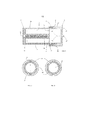
на фиг. 1 показан продольный вид в разрезе картриджа и мундштука согласно первому варианту осуществления настоящего изобретения;in fig. 1 is a longitudinal sectional view of a cartridge and a mouthpiece according to a first embodiment of the present invention;
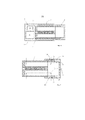
на фиг. 2 показан вид сбоку в разрезе картриджа и мундштука по фиг. 1 в первой конфигурации;in fig. 2 is a cross-sectional side view of the cartridge and mouthpiece of FIG. 1 in the first configuration;
на фиг. 3 показан вид сбоку в разрезе картриджа и мундштука по фиг. 1 во второй конфигурации;in fig. 3 is a side sectional view of the cartridge and mouthpiece of FIG. 1 in a second configuration;
на фиг. 4 показан продольный вид в разрезе картриджа и мундштука по фиг. 1 вместе с устройством, генерирующим аэрозоль;in fig. 4 is a longitudinal sectional view of the cartridge and mouthpiece of FIG. 1 together with an aerosol generating device;
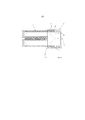
на фиг. 5 показан продольный вид в разрезе картриджа и мундштука согласно второму варианту осуществления настоящего изобретения и в первой конфигурации; иin fig. 5 is a longitudinal sectional view of a cartridge and a mouthpiece according to a second embodiment of the present invention and in a first configuration; and
на фиг. 6 показан продольный вид в разрезе картриджа и мундштука по фиг. 5 во второй конфигурации.in fig. 6 is a longitudinal sectional view of the cartridge and mouthpiece of FIG. 5 in the second configuration.
На фиг. 1 показан продольный вид в разрезе картриджа 2 и мундштука 4 согласно первому варианту осуществления настоящего изобретения. Картридж 2 содержит первое отделение 6, содержащее источник никотина, и второе отделение 8, содержащее источник кислоты. Источник никотина может содержать сорбционный элемент, такой как фитиль из PTFE, с адсорбированным на нем никотином, который размещается внутри первого отделения 6. Источник кислоты может содержать сорбционный элемент, такой как фитиль из PTFE, с адсорбированной на нем кислотой, который размещается внутри второго отделения 8. Кислота может представлять собой, например, молочную кислоту.FIG. 1 shows a longitudinal sectional view of a
Первое отделение 6 содержит первое впускное отверстие 10 для воздуха и первое выпускное отверстие 12 для воздуха, а второе отделение содержит второе впускное отверстие 14 для воздуха и второе выпускное отверстие 16 для воздуха. Во время использования воздух втягивается в картридж 2 через первое и второе впускные отверстия 10, 14 для воздуха и вытягивается из картриджа 2 через первое и второе выпускные отверстия 12, 16 для воздуха, как проиллюстрировано штрихпунктирными линиями на фиг. 1.The
Картридж 2 дополнительно содержит полость 18 для картриджа, проходящую между первым и вторым отделениями 6, 8, и токоприемник 20, расположенный внутри полости 18 для картриджа.The
Мундштук 4 содержит первую часть 22 мундштука и вторую часть 24 мундштука. Первая часть 22 мундштука содержит трубчатую часть, проходящую от расположенного ниже по потоку конца картриджа 2 и образованную цельно с ним. Вторая часть 24 мундштука соединена с возможностью поворота с первой частью 22 мундштука таким образом, что вторая часть 24 мундштука может поворачиваться по отношению к первой части 24 мундштука.The
Мундштук 4 определяет камеру 26, в которой размещается поток воздуха из первого и второго выпускных отверстий 12, 16 для воздуха. Во время использования пар никотина и пар кислоты, поступающие в камеру 26 из первого и второго отделений 6, 8, смешиваются вместе и вступают в реакцию с образованием аэрозоля из частиц соли никотина, который доставляется пользователю через третье выпускное отверстие 27 для воздуха в мундштуке 4.The
Первая часть 22 мундштука содержит первое множество отверстий 28, и вторая часть 24 мундштука содержит второе множество отверстий 30. Комбинация из первого множества отверстий 28 и второго множества отверстий 30 образует третье впускное отверстие 32 для воздуха, через которое воздух может поступать в камеру 26 непосредственно с внешней стороны мундштука 4.The
Вторая часть 24 мундштука выполнена с возможностью поворота по отношению к первой части 22 мундштука из первого положения, показанного на фиг. 2, через промежуточное второе положение, в третье положение, показанное на фиг. 3. В первом положении, показанном на фиг. 2, первое множество отверстий 28 полностью выровнено со вторым множеством отверстий 30 для обеспечения максимальной площади сечения потока третьего впускного отверстия 32 для воздуха. В третьем положении, показанном на фиг. 3, первое множество отверстий 28 не выравнивается с любой частью второго множества отверстий 30, таким образом третье впускное отверстие 32 для воздуха полностью заблокировано. Следовательно, третье положение, показанное на фиг. 3, представляет минимальную площадь сечения потока (нулевую) третьего впускного отверстия 32 для воздуха. В промежуточном втором положение (не показано) между первым и третьим положениями, первое множество отверстий 28 частично выровнено со вторым множеством отверстий 30, таким образом третье впускное отверстие 32 для воздуха только частично заблокировано. Следовательно, во втором положении третье впускное отверстие 32 для воздуха имеет площадь сечения потока, находящуюся между максимальной площадью сечения потока и минимальной площадью сечения потока. За счет изменения площади сечения потока третьего впускного отверстия 32 для воздуха, пользователь может изменять скорость потока воздуха, поступающего в камеру 26 через третье впускное отверстие 32 для воздуха, которая изменяет общую доставку частиц соли никотина на единицу объема потока воздуха через третье выпускное отверстие 27 для воздуха.The
На фиг. 4 показан картридж 2 и мундштук 4 по фиг. 1 вместе с устройством 40, генерирующим аэрозоль. Устройство 40, генерирующее аэрозоль, содержит корпус 42, определяющий полость 44 для вмещения картриджа 2 и индуктивный нагреватель 46, окружающий полость 44. Устройство 40 дополнительно содержит источник 48 питания и контроллер 50 для управления подачей питания от источника 48 питания до индуктивного нагревателя 46. Во время использования контроллер 50 управляет подачей питания от источника 48 питания до индуктивного нагревателя 46 для нагревания токоприемника 20, размещенного внутри полости 18 картриджа 2. Токоприемник 20 после нагревания нагревает первое отделение 6 и второе отделение 8 для испарения никотина и кислоты, размещенных внутри первого и второго отделений 6, 8.FIG. 4 shows
На фиг. 5 и 6 показан картридж 2 и мундштук 104 согласно второму согласно варианту осуществления настоящего изобретения. Картридж 2 идентичен с картриджем 2, описанным со ссылкой на фиг. 1. Мундштук 104 подобен мундштуку 4, описанному со ссылкой на фиг. 1 и одинаковые ссылочные позиции используются для обозначения одинаковых частей.FIG. 5 and 6 show a
Мундштук 104, показанный на фиг. 5 и 6, содержит первую часть 122 мундштука и вторую часть 124 мундштука. Первая часть 122 мундштука содержит трубчатую часть, проходящую от расположенного ниже по потоку конца картриджа 2 и образованную цельно с ним. Вторая часть 124 мундштука соединена с возможностью скольжения с первой частью 122 мундштука таким образом, что вторая часть 124 мундштука может скользить по отношению к первой части 124 мундштука.The
Мундштук 104 определяет камеру 26, в которой размещается поток воздуха из первого и второго выпускных отверстий 12, 16 для воздуха. Во время использования пар никотина и пар кислоты, поступающие в камеру 26 из первого и второго отделений 6, 8, смешиваются вместе и вступают в реакцию с образованием аэрозоля из частиц соли никотина, который доставляется пользователю через третье выпускное отверстие 27 для воздуха в мундштуке 104.The
Первая часть 122 мундштука содержит первое множество отверстий 28, и вторая часть 124 мундштука содержит второе множество отверстий 30. Комбинация из первого множества отверстий 28 и второго множества отверстий 30 образует третье впускное отверстие 32 для воздуха, через которое воздух может поступать в камеру 26 непосредственно с внешней стороны мундштука 104.The
Вторая часть 124 мундштука выполнена с возможностью скольжения по отношению к первой части 122 мундштука из первого положения, показанного на фиг. 5, через промежуточное второе положение, в третье положение, показанное на фиг. 6. В первом положении, показанном на фиг. 5, первое множество отверстий 28 полностью выровнено со вторым множеством отверстий 30 для обеспечения максимальной площади сечения потока третьего впускного отверстия 32 для воздуха. В третьем положении, показанном на фиг. 6, первое множество отверстий 28 не выравнивается с любой частью второго множества отверстий 30, таким образом третье впускное отверстие 32 для воздуха полностью заблокировано. Следовательно, третье положение, показанное на фиг. 6, представляет минимальную площадь сечения потока (нулевую) третьего впускного отверстия 32 для воздуха. В промежуточном втором положение (не показано) между первым и третьим положениями, первое множество отверстий 28 частично выровнено со вторым множеством отверстий 30, таким образом третье впускное отверстие 32 для воздуха только частично заблокировано. Следовательно, во втором положении третье впускное отверстие 32 для воздуха имеет площадь сечения потока, находящуюся между максимальной площадью сечения потока и минимальной площадью сечения потока. За счет изменения площади сечения потока третьего впускного отверстия 32 для воздуха, пользователь может изменять скорость потока воздуха, поступающего в камеру 26 через третье впускное отверстие 32 для воздуха, которая изменяет общую доставку частиц соли никотина на единицу объема потока воздуха через третье выпускное отверстие 27 для воздуха.The
Claims (21)
Applications Claiming Priority (3)
| Application Number | Priority Date | Filing Date | Title |
|---|---|---|---|
| EP15201767.9 | 2015-12-21 | ||
| EP15201767 | 2015-12-21 | ||
| PCT/EP2016/081807 WO2017108721A1 (en) | 2015-12-21 | 2016-12-19 | Aerosol-generating system comprising variable air inlet |
Publications (3)
| Publication Number | Publication Date |
|---|---|
| RU2018126636A RU2018126636A (en) | 2020-01-23 |
| RU2018126636A3 RU2018126636A3 (en) | 2020-05-27 |
| RU2728103C2 true RU2728103C2 (en) | 2020-07-28 |
Family
ID=54979528
Family Applications (1)
| Application Number | Title | Priority Date | Filing Date |
|---|---|---|---|
| RU2018126636A RU2728103C2 (en) | 2015-12-21 | 2016-12-19 | Aerosol-generating system comprising a variable air inlet |
Country Status (10)
| Country | Link |
|---|---|
| US (1) | US11252991B2 (en) |
| EP (1) | EP3393282B1 (en) |
| JP (1) | JP6818765B2 (en) |
| KR (1) | KR102657250B1 (en) |
| CN (2) | CN108289512A (en) |
| CA (1) | CA3003383A1 (en) |
| IL (1) | IL259235A (en) |
| MX (1) | MX2018007314A (en) |
| RU (1) | RU2728103C2 (en) |
| WO (1) | WO2017108721A1 (en) |
Cited By (1)
| Publication number | Priority date | Publication date | Assignee | Title |
|---|---|---|---|---|
| RU2857871C2 (en) * | 2021-12-02 | 2026-03-11 | Филип Моррис Продактс С.А. | Mouthpiece for aerosol-generating device with locking/unlocking of valve element |
Families Citing this family (50)
| Publication number | Priority date | Publication date | Assignee | Title |
|---|---|---|---|---|
| US20170055574A1 (en) | 2015-08-31 | 2017-03-02 | British American Tobacco (Investments) Limited | Cartridge for use with apparatus for heating smokable material |
| US20170119049A1 (en) | 2015-10-30 | 2017-05-04 | British American Tobacco (Investments) Limited | Article for Use with Apparatus for Heating Smokable Material |
| US20180317554A1 (en) | 2015-10-30 | 2018-11-08 | British American Tobacco (Investments) Limited | Article for use with apparatus for heating smokable material |
| US20170119051A1 (en) | 2015-10-30 | 2017-05-04 | British American Tobacco (Investments) Limited | Article for Use with Apparatus for Heating Smokable Material |
| US20170119050A1 (en) | 2015-10-30 | 2017-05-04 | British American Tobacco (Investments) Limited | Article for Use with Apparatus for Heating Smokable Material |
| CN109310157A (en) | 2016-04-22 | 2019-02-05 | 尤尔实验室有限公司 | Aerosol device with spacer material |
| KR102903953B1 (en) * | 2016-06-29 | 2025-12-23 | 니코벤처스 트레이딩 리미티드 | Apparatus for heating smokable material |
| CN109414072A (en) | 2016-06-29 | 2019-03-01 | 英美烟草(投资)有限公司 | For heating the device of smokeable material |
| EP3478102A1 (en) | 2016-06-29 | 2019-05-08 | British American Tobacco (Investments) Ltd | Apparatus for heating smokable material |
| CN109475187A (en) | 2016-07-29 | 2019-03-15 | 菲利普莫里斯生产公司 | Aerosol-generating system comprising a gel-containing cartridge and a device for heating the cartridge |
| MX2019001025A (en) * | 2016-07-29 | 2019-04-25 | Pax Labs Inc | Methods and apparatuses for concentrate vaporization. |
| MX2019005355A (en) * | 2016-11-14 | 2019-07-01 | Philip Morris Products Sa | Aerosol-generating system having variable airflow. |
| WO2018099999A1 (en) * | 2016-11-30 | 2018-06-07 | Philip Morris Products S.A. | Aerosol-generating system having an outer housing |
| JP7285391B2 (en) | 2017-03-17 | 2023-06-02 | アルトリア クライアント サーヴィシス,エルエルシー | closed bottom vaporizer pod |
| KR102719798B1 (en) | 2017-07-10 | 2024-10-21 | 필립모리스 프로덕츠 에스.에이. | Cartridge assembly with ventilation airflow |
| US11229235B2 (en) * | 2017-07-14 | 2022-01-25 | Philip Morris Products S.A. | Aerosol-generating system with concealed ventilation airflow |
| RU2763273C2 (en) * | 2017-07-14 | 2021-12-28 | Филип Моррис Продактс С.А. | Aerosol generating system with ventilation air flow |
| US11324257B2 (en) * | 2017-09-06 | 2022-05-10 | Tuanfang Liu | Electronic cigarette comprising meshed heating disc |
| MX2020002870A (en) | 2017-09-15 | 2020-07-24 | British American Tobacco Investments Ltd | Apparatus for heating smokable material. |
| EP3687320A1 (en) * | 2017-09-25 | 2020-08-05 | JT International SA | Consumable cartridge for an aerosol generation device |
| JP6921304B2 (en) * | 2018-03-05 | 2021-08-18 | 日本たばこ産業株式会社 | Non-combustion heating type smoking goods |
| TWI741161B (en) * | 2018-03-07 | 2021-10-01 | 日商日本煙草產業股份有限公司 | Non-burning heated smoking articles |
| WO2019234245A1 (en) * | 2018-06-07 | 2019-12-12 | Philip Morris Products S.A. | An aerosol generating system, aerosol forming device and a cartridge therefor |
| DE102019109079B4 (en) * | 2018-07-03 | 2020-06-04 | MO GmbH & Co. KG | Aerosol dispersion device |
| GB2576709B (en) * | 2018-08-23 | 2022-03-09 | All Vape Ltd | Vaporiser |
| US12075835B2 (en) | 2018-09-24 | 2024-09-03 | Imperial Tobacco Limited | Aerosol delivery device with support for maintaining position of aerosol generator portion |
| GB201815466D0 (en) * | 2018-09-24 | 2018-11-07 | Nerudia Ltd | Aerosol delivery device |
| WO2020097567A1 (en) | 2018-11-08 | 2020-05-14 | Juul Labs, Inc. | Vaporizer device with more than one heating element |
| US20220192252A1 (en) * | 2019-02-28 | 2022-06-23 | Philip Morris Products S.A. | Aerosol-generating system and aerosol-generating article comprising an aerosol-forming substrate |
| US12329201B2 (en) | 2019-03-22 | 2025-06-17 | Imperial Tobacco Limited | Smoking substitute system |
| EP3711573A1 (en) * | 2019-03-22 | 2020-09-23 | Nerudia Limited | Smoking substitute system |
| EP3711579A1 (en) * | 2019-03-22 | 2020-09-23 | Nerudia Limited | Smoking substitute system |
| EP3782485A1 (en) * | 2019-08-23 | 2021-02-24 | Nerudia Limited | Smoking substitute consumable |
| EP4030949A1 (en) * | 2019-09-19 | 2022-07-27 | Philip Morris Products, S.A. | Aerosol-generating device comprising separate air inlets |
| WO2021053216A1 (en) | 2019-09-20 | 2021-03-25 | Nerudia Limited | A smoking substitute apparatus with electrical contacts |
| KR102533742B1 (en) * | 2020-06-25 | 2023-05-17 | 주식회사 케이티앤지 | Aerosol generating device |
| US20240049791A1 (en) * | 2020-12-17 | 2024-02-15 | Philip Morris Products S.A. | A cartridge for use with an aerosol-generating device |
| US20240225105A9 (en) * | 2021-03-10 | 2024-07-11 | Jt International Sa | Consumable Article with Open Receptacle for an Aerosol Generation Device |
| KR20230071007A (en) * | 2021-11-15 | 2023-05-23 | 주식회사 이노아이티 | Aerosol generator having heating body and liquid absorbing body seperately |
| CN118401128A (en) * | 2021-12-02 | 2024-07-26 | 菲利普莫里斯生产公司 | Mouthpiece for aerosol-generating device with locking/unlocking of valve element |
| KR102728724B1 (en) * | 2022-07-26 | 2024-11-11 | 주식회사 케이티앤지 | Aerosol generating device |
| KR102800080B1 (en) * | 2022-08-25 | 2025-04-28 | 주식회사 케이티앤지 | Aerosol generating system and aerosol generating article |
| KR102751183B1 (en) * | 2022-09-16 | 2025-01-10 | 주식회사 케이티앤지 | Aerosol generating device |
| KR102824242B1 (en) * | 2022-11-02 | 2025-06-25 | 주식회사 케이티앤지 | Inhaler |
| KR102824247B1 (en) * | 2022-11-02 | 2025-06-24 | 주식회사 케이티앤지 | Inhaler |
| WO2024245963A1 (en) * | 2023-05-26 | 2024-12-05 | Philip Morris Products S.A. | Article for generating aerosol |
| CN121152574A (en) * | 2023-05-26 | 2025-12-16 | 菲利普莫里斯生产公司 | Articles for generating aerosols with movable tubes |
| KR20260015880A (en) * | 2023-05-26 | 2026-02-03 | 필립모리스 프로덕츠 에스.에이. | Articles having compartment sealing members |
| GB202313240D0 (en) * | 2023-08-31 | 2023-10-18 | Nicoventures Trading Ltd | An adapter |
| EP4702860A1 (en) * | 2024-08-30 | 2026-03-04 | JT International SA | Mouthpiece portion of an aerosol generating device |
Citations (5)
| Publication number | Priority date | Publication date | Assignee | Title |
|---|---|---|---|---|
| EA015651B1 (en) * | 2007-08-10 | 2011-10-31 | Филип Моррис Продактс С.А. | Distillation-based smoking article |
| RU2012101204A (en) * | 2009-06-17 | 2013-07-27 | Бритиш Америкэн Тобэкко (Инвестментс) Лимитед | AEROSOL GENERATOR |
| US20130192615A1 (en) * | 2012-01-31 | 2013-08-01 | Altria Client Services Inc. | Electronic cigarette |
| WO2015000974A1 (en) * | 2013-07-03 | 2015-01-08 | Philip Morris Products S.A. | Multiple use aerosol-generating system |
| US20150245654A1 (en) * | 2014-02-28 | 2015-09-03 | Beyond Twenty Ltd. | E-cigarette personal vaporizer |
Family Cites Families (18)
| Publication number | Priority date | Publication date | Assignee | Title |
|---|---|---|---|---|
| CN2400701Y (en) | 1999-11-26 | 2000-10-11 | 赵汉明 | Multi-air hole stove with one air intake |
| DE10356925B4 (en) * | 2003-12-05 | 2006-05-11 | Lts Lohmann Therapie-Systeme Ag | Inhaler for basic active pharmaceutical ingredients and process for its preparation |
| US20130071491A1 (en) | 2006-12-18 | 2013-03-21 | Jose De J. Berrios | Extruded Legume Food Products Containing Yeast Autolysate |
| JP2010532672A (en) | 2007-03-30 | 2010-10-14 | デューク ユニバーシティ | Apparatus and method for delivering medication |
| MX336432B (en) * | 2009-03-17 | 2016-01-19 | Philip Morris Products Sa | Tobacco-based nicotine aerosol generation system. |
| UA111630C2 (en) * | 2011-10-06 | 2016-05-25 | Сіс Рісорсез Лтд. | BURNING SYSTEM |
| KR102010104B1 (en) | 2011-12-08 | 2019-08-12 | 필립모리스 프로덕츠 에스.에이. | An aerosol generating device with air flow nozzles |
| RU2602053C2 (en) | 2012-01-03 | 2016-11-10 | Филип Моррис Продактс С.А. | Aerosol generating device and system with improved air flow |
| GB201215282D0 (en) | 2012-08-28 | 2012-10-10 | Kind Consumer Ltd | An inhaler |
| TW201427719A (en) | 2012-12-18 | 2014-07-16 | Philip Morris Products Sa | Encapsulated volatile liquid source for an aerosol-generating system |
| WO2014110119A1 (en) * | 2013-01-08 | 2014-07-17 | L. Perrigo Company | Electronic cigarette |
| ES2651129T3 (en) * | 2013-03-15 | 2018-01-24 | Philip Morris Products S.A. | Aerosol generator system with differential heating |
| CN203762303U (en) | 2014-04-01 | 2014-08-13 | 宁波晶辉光电有限公司 | Smoke-volume adjustable electronic cigarette |
| TWI669073B (en) | 2014-06-24 | 2019-08-21 | 瑞士商菲利浦莫里斯製品股份有限公司 | Aerosol-generating system, aerosol-generating article, aerosol-generating device and method of controlling the reaction stoichiometry |
| WO2016169063A1 (en) * | 2015-04-24 | 2016-10-27 | 深圳麦克韦尔股份有限公司 | Electronic cigarette and atomization device thereof |
| CA2987161A1 (en) | 2015-08-21 | 2017-03-02 | Philip Morris Products, S.A. | A cartridge assembly for an aerosol-generating system and an aerosol-generating system comprising a cartridge assembly |
| KR20150108340A (en) * | 2015-09-07 | 2015-09-25 | 주식회사 제이에프티 | Drip tip for electronic cigarette |
| TR201808893T4 (en) | 2015-12-22 | 2018-07-23 | Philip Morris Products Sa | An aerosol generating system comprising a cartridge and an cartridge for an aerosol generating system. |
-
2016
- 2016-12-19 RU RU2018126636A patent/RU2728103C2/en active
- 2016-12-19 KR KR1020187015304A patent/KR102657250B1/en active Active
- 2016-12-19 CN CN201680069593.4A patent/CN108289512A/en active Pending
- 2016-12-19 EP EP16822449.1A patent/EP3393282B1/en active Active
- 2016-12-19 JP JP2018551506A patent/JP6818765B2/en active Active
- 2016-12-19 WO PCT/EP2016/081807 patent/WO2017108721A1/en not_active Ceased
- 2016-12-19 US US16/061,110 patent/US11252991B2/en active Active
- 2016-12-19 CA CA3003383A patent/CA3003383A1/en not_active Abandoned
- 2016-12-19 MX MX2018007314A patent/MX2018007314A/en unknown
- 2016-12-19 CN CN202410430597.7A patent/CN118319062A/en active Pending
-
2018
- 2018-05-09 IL IL259235A patent/IL259235A/en unknown
Patent Citations (5)
| Publication number | Priority date | Publication date | Assignee | Title |
|---|---|---|---|---|
| EA015651B1 (en) * | 2007-08-10 | 2011-10-31 | Филип Моррис Продактс С.А. | Distillation-based smoking article |
| RU2012101204A (en) * | 2009-06-17 | 2013-07-27 | Бритиш Америкэн Тобэкко (Инвестментс) Лимитед | AEROSOL GENERATOR |
| US20130192615A1 (en) * | 2012-01-31 | 2013-08-01 | Altria Client Services Inc. | Electronic cigarette |
| WO2015000974A1 (en) * | 2013-07-03 | 2015-01-08 | Philip Morris Products S.A. | Multiple use aerosol-generating system |
| US20150245654A1 (en) * | 2014-02-28 | 2015-09-03 | Beyond Twenty Ltd. | E-cigarette personal vaporizer |
Cited By (1)
| Publication number | Priority date | Publication date | Assignee | Title |
|---|---|---|---|---|
| RU2857871C2 (en) * | 2021-12-02 | 2026-03-11 | Филип Моррис Продактс С.А. | Mouthpiece for aerosol-generating device with locking/unlocking of valve element |
Also Published As
| Publication number | Publication date |
|---|---|
| US20180360123A1 (en) | 2018-12-20 |
| CA3003383A1 (en) | 2017-06-29 |
| RU2018126636A3 (en) | 2020-05-27 |
| CN118319062A (en) | 2024-07-12 |
| EP3393282A1 (en) | 2018-10-31 |
| EP3393282B1 (en) | 2020-02-05 |
| JP6818765B2 (en) | 2021-01-20 |
| KR20180095803A (en) | 2018-08-28 |
| WO2017108721A1 (en) | 2017-06-29 |
| US11252991B2 (en) | 2022-02-22 |
| MX2018007314A (en) | 2018-09-11 |
| RU2018126636A (en) | 2020-01-23 |
| CN108289512A (en) | 2018-07-17 |
| JP2019506892A (en) | 2019-03-14 |
| KR102657250B1 (en) | 2024-04-15 |
| IL259235A (en) | 2018-07-31 |
Similar Documents
| Publication | Publication Date | Title |
|---|---|---|
| RU2728103C2 (en) | Aerosol-generating system comprising a variable air inlet | |
| RU2651452C1 (en) | Cartridge for aerosol-generating system and aerosol generating system comprising a cartridge | |
| KR102720306B1 (en) | Cartridge assembly including guide slot | |
| RU2644107C1 (en) | Cartridge for aerosol-generating system and system, generating aerosol, containing cartridge | |
| RU2717637C2 (en) | Cartridge assembly for aerosol generating system and aerosol generating system comprising cartridge assembly | |
| KR102654085B1 (en) | Cartridges for aerosol-generating systems and aerosol-generating systems including cartridges | |
| RU2729551C2 (en) | Spiral activation cartridge assembly | |
| CN108289509B (en) | Cartridge for an aerosol-generating system and aerosol-generating system comprising a cartridge | |
| JP6857194B2 (en) | Cartridge assembly with moving parts | |
| KR20210032949A (en) | Carrier material with inner channel | |
| KR20180103878A (en) | A cartridge assembly having a sliding cartridge body | |
| KR20210031895A (en) | Cartridges with non-uniform cavities | |
| KR102932738B1 (en) | A cartridge for an aerosol-generating system and an aerosol-generating system comprising a cartridge |