RU2725416C1 - Broadband of harmonic audio signal - Google Patents
Broadband of harmonic audio signal Download PDFInfo
- Publication number
- RU2725416C1 RU2725416C1 RU2017103506A RU2017103506A RU2725416C1 RU 2725416 C1 RU2725416 C1 RU 2725416C1 RU 2017103506 A RU2017103506 A RU 2017103506A RU 2017103506 A RU2017103506 A RU 2017103506A RU 2725416 C1 RU2725416 C1 RU 2725416C1
- Authority
- RU
- Russia
- Prior art keywords
- value
- gain
- frequency band
- band
- reconstructed
- Prior art date
Links
Images

Classifications
-
- G—PHYSICS
- G10—MUSICAL INSTRUMENTS; ACOUSTICS
- G10L—SPEECH ANALYSIS OR SYNTHESIS; SPEECH RECOGNITION; SPEECH OR VOICE PROCESSING; SPEECH OR AUDIO CODING OR DECODING
- G10L19/00—Speech or audio signals analysis-synthesis techniques for redundancy reduction, e.g. in vocoders; Coding or decoding of speech or audio signals, using source filter models or psychoacoustic analysis
- G10L19/02—Speech or audio signals analysis-synthesis techniques for redundancy reduction, e.g. in vocoders; Coding or decoding of speech or audio signals, using source filter models or psychoacoustic analysis using spectral analysis, e.g. transform vocoders or subband vocoders
- G10L19/0204—Speech or audio signals analysis-synthesis techniques for redundancy reduction, e.g. in vocoders; Coding or decoding of speech or audio signals, using source filter models or psychoacoustic analysis using spectral analysis, e.g. transform vocoders or subband vocoders using subband decomposition
-
- G—PHYSICS
- G10—MUSICAL INSTRUMENTS; ACOUSTICS
- G10L—SPEECH ANALYSIS OR SYNTHESIS; SPEECH RECOGNITION; SPEECH OR VOICE PROCESSING; SPEECH OR AUDIO CODING OR DECODING
- G10L19/00—Speech or audio signals analysis-synthesis techniques for redundancy reduction, e.g. in vocoders; Coding or decoding of speech or audio signals, using source filter models or psychoacoustic analysis
- G10L19/02—Speech or audio signals analysis-synthesis techniques for redundancy reduction, e.g. in vocoders; Coding or decoding of speech or audio signals, using source filter models or psychoacoustic analysis using spectral analysis, e.g. transform vocoders or subband vocoders
-
- G—PHYSICS
- G10—MUSICAL INSTRUMENTS; ACOUSTICS
- G10L—SPEECH ANALYSIS OR SYNTHESIS; SPEECH RECOGNITION; SPEECH OR VOICE PROCESSING; SPEECH OR AUDIO CODING OR DECODING
- G10L21/00—Processing of the speech or voice signal to produce another audible or non-audible signal, e.g. visual or tactile, in order to modify its quality or its intelligibility
- G10L21/02—Speech enhancement, e.g. noise reduction or echo cancellation
- G10L21/038—Speech enhancement, e.g. noise reduction or echo cancellation using band spreading techniques
- G10L21/0388—Details of processing therefor
-
- G—PHYSICS
- G10—MUSICAL INSTRUMENTS; ACOUSTICS
- G10L—SPEECH ANALYSIS OR SYNTHESIS; SPEECH RECOGNITION; SPEECH OR VOICE PROCESSING; SPEECH OR AUDIO CODING OR DECODING
- G10L19/00—Speech or audio signals analysis-synthesis techniques for redundancy reduction, e.g. in vocoders; Coding or decoding of speech or audio signals, using source filter models or psychoacoustic analysis
- G10L19/012—Comfort noise or silence coding
-
- G—PHYSICS
- G10—MUSICAL INSTRUMENTS; ACOUSTICS
- G10L—SPEECH ANALYSIS OR SYNTHESIS; SPEECH RECOGNITION; SPEECH OR VOICE PROCESSING; SPEECH OR AUDIO CODING OR DECODING
- G10L19/00—Speech or audio signals analysis-synthesis techniques for redundancy reduction, e.g. in vocoders; Coding or decoding of speech or audio signals, using source filter models or psychoacoustic analysis
- G10L19/02—Speech or audio signals analysis-synthesis techniques for redundancy reduction, e.g. in vocoders; Coding or decoding of speech or audio signals, using source filter models or psychoacoustic analysis using spectral analysis, e.g. transform vocoders or subband vocoders
- G10L19/028—Noise substitution, i.e. substituting non-tonal spectral components by noisy source
-
- G—PHYSICS
- G10—MUSICAL INSTRUMENTS; ACOUSTICS
- G10L—SPEECH ANALYSIS OR SYNTHESIS; SPEECH RECOGNITION; SPEECH OR VOICE PROCESSING; SPEECH OR AUDIO CODING OR DECODING
- G10L21/00—Processing of the speech or voice signal to produce another audible or non-audible signal, e.g. visual or tactile, in order to modify its quality or its intelligibility
- G10L21/02—Speech enhancement, e.g. noise reduction or echo cancellation
- G10L21/0208—Noise filtering
- G10L21/0216—Noise filtering characterised by the method used for estimating noise
- G10L21/0232—Processing in the frequency domain
-
- G—PHYSICS
- G10—MUSICAL INSTRUMENTS; ACOUSTICS
- G10L—SPEECH ANALYSIS OR SYNTHESIS; SPEECH RECOGNITION; SPEECH OR VOICE PROCESSING; SPEECH OR AUDIO CODING OR DECODING
- G10L21/00—Processing of the speech or voice signal to produce another audible or non-audible signal, e.g. visual or tactile, in order to modify its quality or its intelligibility
- G10L21/02—Speech enhancement, e.g. noise reduction or echo cancellation
- G10L21/0316—Speech enhancement, e.g. noise reduction or echo cancellation by changing the amplitude
- G10L21/0364—Speech enhancement, e.g. noise reduction or echo cancellation by changing the amplitude for improving intelligibility
-
- G—PHYSICS
- G10—MUSICAL INSTRUMENTS; ACOUSTICS
- G10L—SPEECH ANALYSIS OR SYNTHESIS; SPEECH RECOGNITION; SPEECH OR VOICE PROCESSING; SPEECH OR AUDIO CODING OR DECODING
- G10L21/00—Processing of the speech or voice signal to produce another audible or non-audible signal, e.g. visual or tactile, in order to modify its quality or its intelligibility
- G10L21/02—Speech enhancement, e.g. noise reduction or echo cancellation
- G10L21/038—Speech enhancement, e.g. noise reduction or echo cancellation using band spreading techniques
-
- G—PHYSICS
- G10—MUSICAL INSTRUMENTS; ACOUSTICS
- G10L—SPEECH ANALYSIS OR SYNTHESIS; SPEECH RECOGNITION; SPEECH OR VOICE PROCESSING; SPEECH OR AUDIO CODING OR DECODING
- G10L25/00—Speech or voice analysis techniques not restricted to a single one of groups G10L15/00 - G10L21/00
- G10L25/03—Speech or voice analysis techniques not restricted to a single one of groups G10L15/00 - G10L21/00 characterised by the type of extracted parameters
- G10L25/21—Speech or voice analysis techniques not restricted to a single one of groups G10L15/00 - G10L21/00 characterised by the type of extracted parameters the extracted parameters being power information
Abstract
Description
Область техники, к которой относится изобретениеFIELD OF THE INVENTION
Предлагаемая технология относится к кодированию и декодированию аудиосигналов, и, в частности, к поддержке расширения полосы частот (BWE) гармонических аудиосигналов.The proposed technology relates to the encoding and decoding of audio signals, and, in particular, to support the extension of the frequency band (BWE) of harmonic audio signals.
Уровень техникиState of the art
Кодирование на основе преобразования представляет собой наиболее часто используемую схему в современных системах сжатия/передачи аудиосигнала. Основные этапы в такой схеме состоят в том, что вначале преобразуют короткий блок колебаний сигнала в области частоты, используя соответствующее преобразование, например, DFT (дискретное преобразование Фурье), DCT (дискретное косинусное преобразование), или MDCT (модифицированное дискретное косинусное преобразование). Коэффициенты преобразования затем квантуют, передают или сохраняют и затем используют для реконструкции аудиосигнала. Такой подход хорошо работает для общих аудиосигналов, но требуют достаточно большой частоты передачи битов для формирования достаточно хорошего представления коэффициентов преобразования. Ниже будет представлен обзор на высоком уровне таких схем кодирования в области преобразования.Conversion-based coding is the most commonly used circuit in modern audio compression / transmission systems. The main steps in such a scheme are to first convert a short block of signal oscillations in the frequency domain using the appropriate transform, for example, DFT (discrete Fourier transform), DCT (discrete cosine transform), or MDCT (modified discrete cosine transform). The transform coefficients are then quantized, transmitted, or stored, and then used to reconstruct the audio signal. This approach works well for general audio signals, but requires a sufficiently high bit rate to form a sufficiently good representation of the conversion coefficients. A high-level overview of such transform coding schemes will be presented below.
На основе от блока к блоку форму колебаний, которая требуется для кодирования, преобразуют в область частоты. Одно обычно используемое преобразование, применяемое с этой целью, представляет собой, так называемое, модифицированное дискретное косинусное преобразование (MDCT). Полученный таким образом вектор преобразования области частоты разделяют на огибающую спектра (медленно изменяющаяся энергия) и спектральные остатки. Спектральный остаток получают путем нормализации полученного вектора в области частоты с упомянутой спектральной огибающей. Спектральную огибающую квантуют, и показатели квантования передают в декодер. Затем квантованную огибающую спектра используют, как входные данные для алгоритма распределения битов, и биты для кодирования остаточных векторов распределяют на основе характеристик спектральной огибающей. В качестве результата на этом этапе определенное количество битов назначают для разных частей остатка (остаточные векторы или "подвекторы"). Некоторые остаточные векторы не принимают какие-либо биты и должны быть заполнены шумами или расширены на полосу частот. Как правило, кодирование остаточных векторов представляет собой процедуры, выполняемые в два этапа; вначале кодируют амплитуду элементов векторов и затем кодируют знак (который не должен противоречить "фазе", которая ассоциирована, например, с преобразованиями Фурье) ненулевых элементов. Показатели квантования для остаточной амплитуды и знака передают в декодер, где остаточные данные и спектральную огибающую комбинируют и, в конечном итоге, преобразуют снова в область времени.Based on the block-to-block basis, the waveform that is required for encoding is converted into a frequency domain. One commonly used transform used for this purpose is the so-called modified discrete cosine transform (MDCT). The frequency domain transform vector thus obtained is divided into the spectral envelope (slowly varying energy) and spectral residues. The spectral residue is obtained by normalizing the resulting vector in the frequency domain with the mentioned spectral envelope. The spectral envelope is quantized, and quantization indicators are transmitted to the decoder. The quantized spectral envelope is then used as input to the bit allocation algorithm, and bits for encoding the residual vectors are allocated based on the characteristics of the spectral envelope. As a result, at this stage, a certain number of bits are assigned to different parts of the remainder (residual vectors or "subvectors"). Some residual vectors do not accept any bits and must be filled with noise or extended into the frequency band. As a rule, coding of residual vectors is a procedure performed in two stages; first, they encode the amplitude of the elements of the vectors and then encode the sign (which should not contradict the "phase", which is associated, for example, with Fourier transforms) of nonzero elements. The quantization indices for the residual amplitude and sign are transmitted to the decoder, where the residual data and the spectral envelope are combined and, ultimately, converted again to the time domain.
Пропускная способность в телекоммуникационных сетях постоянно повышается. Однако, несмотря на увеличение пропускной способности, все еще существует сильное побуждение для ограничения требуемой полосы пропускания для канала передачи данных. В мобильных сетях меньшая полоса пропускания для каждого вызова позволяет обеспечить меньшее потребление энергии, как в мобильном устройстве, так и в базовой станции, обслуживающей это устройство. Это можно перевести в экономию энергии и стоимости для оператора мобильной связи, в то время как конечный пользователь получит удлиненный срок службы батареи и увеличенное время на разговоры. Кроме того, чем меньше полоса пропускания, потребляемая каждым пользователем, тем большее количество пользователей может быть обслужено (параллельно) мобильной сетью.Throughput in telecommunication networks is constantly increasing. However, despite the increase in throughput, there is still a strong motivation to limit the required bandwidth for the data channel. In mobile networks, a smaller bandwidth for each call allows for lower energy consumption, both in the mobile device and in the base station serving this device. This can translate into energy and cost savings for the mobile operator, while the end user will get longer battery life and longer talk time. In addition, the smaller the bandwidth consumed by each user, the more users can be served (in parallel) by the mobile network.
Один из способов улучшения качества аудиосигнала, который требуется передать, используя низкую или умеренную частоту передачи битов, состоит в том, чтобы фокусировать доступные биты для точного представления низких частот в аудиосигнале. Затем технологии BWE могут использоваться для моделирования более высоких частот на основе более низких частот, для которых требуется только малое количество битов. Основа этих технологий состоит в том, что чувствительность слуховой системы человека зависит от частоты. В частности, слуховая система человека, то есть, наше слуховое восприятие в меньшей степени является точной для более высоких частот. One way to improve the quality of the audio signal to be transmitted using a low or moderate bit rate is to focus the available bits to accurately represent the low frequencies in the audio signal. BWE technologies can then be used to model higher frequencies based on lower frequencies, which require only a small number of bits. The basis of these technologies is that the sensitivity of the human auditory system depends on the frequency. In particular, the human auditory system, that is, our auditory perception is less accurate for higher frequencies.
В типичной схеме BWE в области частоты коэффициенты преобразования высокой частоты группируют по полосам. Усиление (энергию) для каждой частоты рассчитывают, квантуют и передают (в декодер сигнала). В декодере, перевернутую или транслированную и нормализованную по энергии версию принятых коэффициентов низкой частоты масштабируют с усилением высокой частоты. Таким образом, BWE не является "абсолютно слепым", поскольку, по меньшей мере, спектральная энергия напоминает целевой сигнал в полосе высокой частоты.In a typical BWE scheme in the frequency domain, high frequency transform coefficients are grouped into bands. The gain (energy) for each frequency is calculated, quantized, and transmitted (to a signal decoder). At the decoder, an inverted or translated and energy normalized version of the received low frequency coefficients is scaled with high frequency amplification. Thus, the BWE is not “completely blind” because at least the spectral energy resembles a target signal in a high frequency band.
Однако BWE определенных аудиосигналов может привести к тому, что аудиосигналы будут содержать дефекты, которые являются раздражающими для слушателя. However, the BWE of certain audio signals may cause the audio signals to contain defects that are annoying to the listener.
Сущность изобретенияSUMMARY OF THE INVENTION
Здесь предложена технология для поддержки и улучшения BWE гармонических аудиосигналов.It offers technology to support and improve BWE harmonic audio signals.
В соответствии с первым аспектом предложен способ преобразования аудиодекодера. Способ выполнен с возможностью поддержки расширения полосы частот BWE гармонического аудиосигнала. Предложенный способ может содержать прием множества значений усиления, ассоциированных с полосой b частот, и количества соседних полос частот для полосы b. Предложенный способ дополнительно содержит: определяют, содержит ли реконструированная соответствующая полоса b’ расширенной области частот полосы частот спектральный пик. Кроме того, если полоса частот содержит, по меньшей мере, один спектральный пик, способ содержит: устанавливают значение Gb усиления, ассоциированное с полосой b’ для первого значения на основе принятого множества значений усиления. Если полоса не содержит какой-либо спектральный пик, способ содержит: устанавливают значение Gb усиления, ассоциированное с полосой b’, до второго значения на основе принятого множества значений усиления. Таким образом, обеспечивается возможность сведения значений усиления, в соответствии с положениями пика в расширенной полосе частот спектра.In accordance with a first aspect, a method for converting an audio decoder is provided. The method is configured to support the extension of the frequency band of the BWE harmonic audio signal. The proposed method may comprise receiving a plurality of gain values associated with a frequency band b and the number of neighboring frequency bands for a band b. The proposed method further comprises: determining whether the reconstructed corresponding band b ’of the expanded frequency domain of the frequency band contains a spectral peak. In addition, if the frequency band contains at least one spectral peak, the method comprises: setting the gain value Gb associated with the band b ’for the first value based on the received plurality of gain values. If the band does not contain any spectral peak, the method contains: set the gain value Gb associated with the band b ’to a second value based on the received plurality of gain values. Thus, it is possible to reduce the gain values in accordance with the peak positions in the extended frequency band of the spectrum.
Кроме того, способ может содержать: принимают параметр или коэффициент б, отражающий взаимоотношения между энергией пика и энергией минимального уровня шума, по меньшей мере, участка для части высокой частоты исходного сигнала. Способ может дополнительно содержать: смешивают коэффициенты преобразования соответствующего реконструированного участка высокой частоты с шумами на основе принятого коэффициента б. Таким образом, обеспечивается возможность реконструкции/эмуляции шумовых характеристик части высокой частоты оригинального сигнала.In addition, the method may include: take a parameter or coefficient b, reflecting the relationship between the energy of the peak and the energy of the minimum noise level, at least a portion for part of the high frequency of the original signal. The method may further comprise: mixing the conversion coefficients of the corresponding reconstructed high frequency section with noise based on the received coefficient b. Thus, it is possible to reconstruct / emulate the noise characteristics of a part of the high frequency of the original signal.
В соответствии со вторым аспектом предложен аудиодекодер преобразования или кодек для поддержки расширения полосы пропускания BWE или гармонического аудиосигнала. Аудиокодек преобразования может содержать функциональные модули и выполнен с возможностью выполнения действий, описанных выше. Кроме того, предложен аудиокодер преобразования или кодек, содержащий функциональные блоки и выполненный с возможностью вывода и предоставления одного или больше параметров, обеспечивающих описанное здесь смешивание шумов, когда их предоставляют в аудиодекодер преобразования.In accordance with a second aspect, an audio conversion decoder or codec is provided to support BWE bandwidth extension or harmonic audio signal. The audio conversion codec may contain functional modules and is configured to perform the actions described above. In addition, an audio conversion encoder or codec is provided comprising functional blocks and configured to output and provide one or more parameters providing noise mixing described herein when provided in a conversion audio decoder.
В соответствии с третьим аспектом, предложен терминал пользователя, который содержит аудиокодек преобразования, в соответствии со вторым аспектом. Терминал пользователя может представлять собой устройство, такое как мобильный терминал, планшетный компьютер, компьютер, смартфон и т.п.In accordance with a third aspect, a user terminal is provided that comprises an audio conversion codec in accordance with a second aspect. A user terminal may be a device, such as a mobile terminal, a tablet computer, a computer, a smartphone, or the like.
Краткое описание чертежейBrief Description of the Drawings
Предложенная технология будет более подробно описана ниже со ссылкой на примерные варианты осуществления и со ссылкой на приложенные чертежи, на которых:The proposed technology will be described in more detail below with reference to exemplary embodiments and with reference to the attached drawings, in which:
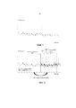
на фиг. 1 показан гармонический аудиоспектр, то есть, спектр гармонического аудиосигнала. Такой тип спектра является типичным для, например, звуков одного инструмента, вокальных звуков и т.д.; in FIG. 1 shows a harmonic audio spectrum, that is, a spectrum of a harmonic audio signal. This type of spectrum is typical for, for example, sounds of one instrument, vocal sounds, etc .;
на фиг. 2 показан гармонический аудио спектр с расширенной полосой частот;in FIG. 2 shows a harmonic audio spectrum with an extended frequency band;
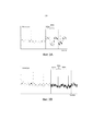
на фиг. 3a показан спектр BWE (также представленный на фиг. 2), масштабированный с соответствующими коэффициентами усиления ![]()
![]()
![]()
![]()
на фиг. 3b показан спектр BWE, масштабированный с модифицированными коэффициентами ![]()
![]()
![]()
![]()
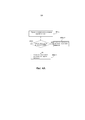
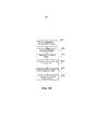
на фиг. 4a и 4b показаны блок-схемы последовательности операций, иллюстрирующие действия в процедуре аудиодекодера преобразовании, в соответствии с примерными вариантами осуществления;in FIG. 4a and 4b are flowcharts illustrating steps in an audio decoder decoder procedure in accordance with exemplary embodiments;
на фиг. 5 показана блок-схема, иллюстрирующая аудиодекодер преобразования, в соответствии с примерным вариантом осуществления;in FIG. 5 is a block diagram illustrating an audio conversion decoder in accordance with an exemplary embodiment;
на фиг. 6 показана блок-схема последовательности операций, иллюстрирующая действия в процедуре аудиокодера преобразовании, в соответствии с примерным вариантом осуществления;in FIG. 6 is a flowchart illustrating actions in an audio encoder transform procedure in accordance with an exemplary embodiment;
на фиг. 7 показана блок-схема, иллюстрирующая аудиокодер преобразования, в соответствии с примерным вариантом осуществления;in FIG. 7 is a block diagram illustrating an audio conversion encoder in accordance with an exemplary embodiment;
на фиг. 8 показана блок-схема, иллюстрирующая компоновку в аудиодекодере преобразования, в соответствии с примерным вариантом осуществления.in FIG. 8 is a block diagram illustrating a layout in an audio conversion decoder in accordance with an exemplary embodiment.
Подробное описание изобретенияDETAILED DESCRIPTION OF THE INVENTION
Расширение полосы частот гармонических аудиосигналов ассоциировано с некоторыми проблемами, как обозначено выше. В декодере, когда низкую полосу, то есть, часть полосы частот, которая была кодирована, передана и декодирована, переворачивают или транслируют в форму для высокой полосы, нет уверенности в том, что спектральные пики заканчиваются в тех же полосах, что и спектральные пики в оригинальном сигнале, или "истинной" высокой полосе. Спектральный пик из низкой полосы может заканчиваться в полосе, где оригинальный сигнал не имеет пика. Также возможен противоположный случай, то есть, когда часть сигнала низкой полосы, которая не имеет пика, заканчивается (после переворачивания или трансляции) в полосе, где оригинальный сигнал имеет пик. Пример гармонического спектра представлен на фиг. 1, и пример концепции BWE представлен на фиг. 2, которая будет дополнительно описана ниже.The bandwidth extension of harmonic audio signals is associated with some problems, as indicated above. In the decoder, when the low band, that is, the part of the frequency band that has been encoded, transmitted and decoded, is turned upside down or translated into a high band form, there is no certainty that the spectral peaks end in the same bands as the spectral peaks in original signal, or “true” high band. A spectral peak from a low band may end in a band where the original signal has no peak. The opposite case is also possible, that is, when the part of the low-band signal that does not have a peak ends (after flipping or broadcasting) in the band where the original signal has a peak. An example of a harmonic spectrum is shown in FIG. 1, and an example of a BWE concept is shown in FIG. 2, which will be further described below.
Эффект, описанный выше, может привести к серьезному снижению качества для сигналов с, в основном, гармоническим содержанием. Причина этого состоит в том, что такое рассогласование между положениями пиков и усиления приводит либо к ненужной аттенюации пика, или к усилению спектральных коэффициентов низкой энергии между двумя спектральными пиками.The effect described above can lead to a serious decrease in quality for signals with mainly harmonic content. The reason for this is that such a mismatch between the positions of the peaks and the gain leads either to unnecessary attenuation of the peak, or to an increase in the spectral coefficients of low energy between the two spectral peaks.
Описанное здесь решение относится к новому способу, для управления усилениями в полосах, в расширенной области полосы частот, на основе информации о положениях пиков. Кроме того, предложенный здесь алгоритм BWE может управлять "спектральными пиками по коэффициенту минимального уровня шума", используя переданные уровни соединения шумов. Это приводит к получению BWE, который сохраняет величину структуры в расширенных высоких частотах.The solution described here relates to a new method for controlling amplifications in the bands, in the extended region of the frequency band, based on information about the positions of the peaks. In addition, the BWE algorithm proposed here can control “spectral peaks in terms of the noise floor coefficient” using the transmitted noise coupling levels. This results in a BWE that preserves the magnitude of the structure at extended high frequencies.
Решение, описанное здесь, пригодно для использования с гармоническими аудиосигналами. На фиг. 1 показан частотный спектр гармонического аудиосигнала, который также может быть обозначен, как гармонические спектры. Как можно видеть на чертеже, спектр содержит пики. Такой тип спектра является типичным, например, для звуков одного инструмента, такого, как флейта, или вокальных звуков, и т.д.The solution described here is suitable for use with harmonic audio signals. In FIG. 1 shows the frequency spectrum of a harmonic audio signal, which can also be referred to as harmonic spectra. As can be seen in the drawing, the spectrum contains peaks. This type of spectrum is typical, for example, for sounds of one instrument, such as a flute, or vocal sounds, etc.
Здесь будут описаны две части спектра гармонического аудиосигнала. Одна нижняя часть, содержащая более низкие частоты, где "нижний" обозначает более нижний, чем часть, которая будет подвергнута расширению полосы частот; и одна верхняя часть, содержащая более высокие частоты, то есть, более высокие, чем нижняя часть. Выражения, такие как “нижняя часть” или “низкие/более низкие частоты”, используемые здесь, относятся к части гармонического аудиоспектра ниже частоты перехода BWE (см. фиг. 2). Аналогично, выражения, такие как “верхняя часть” или “высокие/более высокие частоты”, относятся к части гармонического аудиоспектра выше частоты перехода BWE (см. фиг. 2).Here, two parts of the spectrum of a harmonic audio signal will be described. One lower part containing lower frequencies, where “lower” means lower than the part to be expanded; and one upper part containing higher frequencies, that is, higher than the lower part. Expressions such as “lower” or “lower / lower frequencies” used here refer to the part of the harmonic audio spectrum below the BWE transition frequency (see FIG. 2). Similarly, expressions such as “upper” or “higher / higher frequencies” refer to the part of the harmonic audio spectrum above the BWE transition frequency (see FIG. 2).
На фиг. 2 показан спектр гармонического аудиосигнала. Здесь эти две части, описанные ниже, можно рассматривать, как более низкую часть, находящуюся слева от частоты перехода BWE, и верхнюю часть, находящуюся справа от частоты перехода BWE. На фиг. 2 оригинальный спектр, то есть, спектр оригинального аудиосигнала (как можно видеть на стороне кодера) представлен светло-серым цветом. Расширенная часть полосы частот спектра представлена темным/более темным серым цветом. Расширенная часть полосы частот спектра не кодируется кодером, но восстанавливается декодером, используя принятую нижнюю часть спектра, как описано выше. На фиг. 2 можно видеть, для сравнения, как оригинальный (светло-серый) спектр, так и спектр BWE (темно-серый) для более высоких частот. Оригинальный спектр для более высоких частот является неизвестным для декодера, за исключением величины усиления для каждой полосы BWE (или высокочастотной полосы). Полосы BWE разделены пунктирными линиями на фиг. 2.In FIG. 2 shows a spectrum of a harmonic audio signal. Here, these two parts, described below, can be considered as the lower part located to the left of the BWE transition frequency, and the upper part located to the right of the BWE transition frequency. In FIG. 2 the original spectrum, that is, the spectrum of the original audio signal (as can be seen on the encoder side) is represented in light gray. The extended portion of the spectrum bandwidth is represented by dark / darker gray. The extended part of the spectrum bandwidth is not encoded by the encoder, but is restored by the decoder using the received lower part of the spectrum, as described above. In FIG. 2, for comparison, both the original (light gray) spectrum and the BWE spectrum (dark gray) for higher frequencies can be seen. The original spectrum for higher frequencies is unknown to the decoder, except for the gain value for each BWE band (or high-frequency band). BWE strips are separated by dashed lines in FIG. 2.
Фиг. 3a можно рассмотреть для лучшего понимания проблемы рассогласования между значениями усиления, и положениями пика в расширенной части полосы частот спектра. В полосе 302a исходный спектр содержит пик, но восстановленный спектр BWE не содержит пик. Это можно видеть в полосе 202 на фиг. 2. Таким образом, когда коэффициент усиления, который рассчитывают для исходной полосы, содержащей пик, применяют для полосы BWE, которая не содержит пик, спектральные коэффициенты с низкой энергией в полосе BWE усиливают, как можно видеть в полосе 302a.FIG. 3a may be considered for a better understanding of the mismatch between gain values and peak positions in the extended portion of the spectrum bandwidth. In
Полоса 304a на фиг. 3a представляет противоположную ситуацию, то есть, когда соответствующая полоса исходного спектра не содержит пик, но соответствующая полоса восстановленного спектра BWE содержит пик. Таким образом, полученный коэффициент усиления для полосы (принятый из кодера) рассчитывают для полосы с низкой энергией. Когда этот коэффициент усиления применяют для соответствующей полосы, которая содержит пик, в результате получают ослабленный пик, как можно видеть в полосе 304a на фиг. 3a. С точки зрения перцепционного или психоакустического восприятия, ситуация, показанная в полосе 302a, хуже для слушателя, чем ситуация в полосе 304a, по различным причинам. Таким образом, для простоты описания; обычно для слушателя более неприятно испытывать ненормальное присутствие компонента звука, чем ненормальное отсутствие компонента звука.
Ниже будет описан пример нового алгоритма BWE, иллюстрирующий описанную здесь концепцию.An example of a new BWE algorithm will be described below, illustrating the concept described here.
Пусть![]()
![]()
![]()
![]()
![]()
![]()
![]()
![]()
![]()
![]()
![]()
![]()
![]()
![]()
Первый этап в алгоритме BWE состоит в расчете коэффициента усиления для всех полос:The first step in the BWE algorithm is to calculate the gain for all bands:

Эти коэффициенты усиления квантуют ![]()
![]()
Второй этап (который является необязательным) в алгоритме BWE состоит в расчете параметра смешения шумов или коэффициента ![]()
![]()
![]()
![]()
![]()
![]()

Здесь параметр б был выведен в соответствии с Уравнением (3), представленным ниже. Однако точное используемое выражение может быть выбрано разными путями, например, в зависимости от того, что является соответствующим для используемого типа кодека или квантователя, и т.д.Here, parameter b was derived in accordance with Equation (3) below. However, the exact expression used can be chosen in different ways, for example, depending on what is appropriate for the type of codec or quantizer used, etc.

Энергия пика и уровня шумов может быть рассчитана, например, путем отслеживания соответствующего максимального и минимального спектра энергии.The energy of the peak and the noise level can be calculated, for example, by tracking the corresponding maximum and minimum energy spectrum.
Параметр б смеси шумов может быть квантован с использованием малого количества битов. Здесь, в качестве примера, б квантуют 2 битами. Когда параметр б смеси шумов квантуют, получают параметр ![]()
![]()
![]()
![]()
![]()
![]()
Операции декодера:Decoder Operations:
Декодер выделяет из потока битов набор рассчитанных квантованных коэффициентов усиления ![]()
![]()
![]()
![]()
Пусть![]()
![]()
![]()
![]()
![]()
![]()
![]()
![]()
![]()
![]()
Диапазон параметра или коэффициента смешивания шумов можно установить различным способами. Например, здесь, диапазон для коэффициента смешивания шумов был установлен, как ![]()
![]()
В решениях предшествующего уровня техники набор принятых квантованных коэффициентов усиления ![]()
![]()
![]()
![]()
Например, флаг ![]()
![]()
![]()
![]()
![]()
![]()
![]()
![]()
![]()
![]()

Мотивация для такой модификации усиления состоит в следующем: в случае, когда полоса (BWE) содержит пик (![]()
![]()

В случае, когда полоса не содержит пик (![]()
![]()
Случай несоответствия пиков и, таким образом, причина для модификации усиления, представляет собой то, что спектральные полосы размещены на заданной сетке, но положения пиков и пики (после переворачивания или трансляции коэффициентов низкой частоты) изменяются с течением времени. Это может привести к тому, что пики поступают в полосу или выходят из полосы неконтролируемым образом. Таким образом, положения пика в части BWE спектра не обязательно соответствуют положениям пика оригинального сигнала, и, таким образом, может присутствовать несоответствие между коэффициентом усиления, ассоциированным с полосой, и содержанием пика полосы. Пример масштабирования с немодифицированными значениями усиления представлены на фиг. 3a, и масштабирование с модифицированными коэффициентами усилениями показано на фиг. 3b.The case of peak mismatch and, therefore, the reason for modifying the gain, is that the spectral bands are placed on a given grid, but the positions of the peaks and peaks (after flipping or translating low-frequency coefficients) change over time. This can result in peaks entering or leaving the band in an uncontrolled manner. Thus, the peak positions in the BWE portion of the spectrum do not necessarily correspond to the peak positions of the original signal, and thus, there may be a mismatch between the gain associated with the band and the peak content of the band. An example of scaling with unmodified gain values is shown in FIG. 3a, and scaling with modified gain factors is shown in FIG. 3b.
Результат использования модифицированных коэффициентов усиления, как представлено здесь, можно видеть на фиг. 3b. В полосе 302b спектральные коэффициенты низкой энергии больше не являются такими, как усиленные в полосе 302a на фиг. 3a, но их масштабируют с более соответствующим усилением в полосе. Кроме того, пик в полосе 304b больше не ослабляют, как пик в полосе 304a на фиг. 3a. Спектр, иллюстрируемый на фиг. 3b, наиболее вероятно, соответствует аудиосигналу, который является более приятным для слушателя, чем аудиосигнал, соответствующий спектру на фиг. 3a. The result of using modified gains, as presented here, can be seen in FIG. 3b. In the
Таким образом, алгоритм BWE может создавать высокочастотную часть спектра. Поскольку (например, по причинам экономии полосы частот), набор высокочастотных коэффициентов![]()
![]()
![]()
![]()
![]()
![]()
Набор коэффициентов ![]()
![]()
Решение, описанное здесь, представляет собой улучшение концепции BWE, обычно используемой при преобразовании области кодирования аудиосигнала. Представленный алгоритм предотвращает структуру с пиками (отношение пика к уровню шумов) в области BWE, таким образом, обеспечивая улучшенное качество звука реконструированного сигнала.The solution described here is an improvement on the BWE concept commonly used in transforming an audio coding region. The presented algorithm prevents the structure with peaks (the ratio of peak to noise level) in the BWE region, thus providing improved sound quality of the reconstructed signal.
Термин “аудиокодек преобразования” или “кодек преобразования” охватывает любую пару из кодера и декодер, и представляет собой термин, который обычно используется в данной области техники. В данном раскрытии термины “аудиокодер преобразования” или "кодер" и “аудиодекодер преобразования” или "декодер" используются для отдельного описания функций/частей преобразования кодека. Термины “аудиокодер преобразования”/"кодер" и “аудиодекодер преобразования”/"декодер", таким образом, можно взаимно заменять термином "аудиокодек преобразования” или “кодек преобразования”. The term “audio conversion codec” or “conversion codec” encompasses any pair of encoder and decoder, and is a term commonly used in the art. In this disclosure, the terms “audio conversion encoder” or “encoder” and “audio conversion decoder” or “decoder” are used to separately describe the functions / parts of the codec conversion. The terms “conversion audio encoder” / “encoder” and “conversion audio decoder” / “decoder” can thus be mutually replaced by the term “conversion audio codec” or “conversion codec”.
Примерные процедуры декодера, фиг. 4a и 4b.Exemplary decoder procedures, FIG. 4a and 4b.
Примерная процедура, выполняемая в декодере для поддержки расширения полосы частот, BWE, или гармонического аудиосигнала будет описана ниже, со ссылкой на фиг. 4a. Процедура пригодна для использования в аудиокодере преобразования, таком как, например, кодер MDCT или другой кодер. Предполагается, что аудиосигнал, в основном, представляет собой музыку, но также, в качестве альтернативы, может содержать, например, речь.An exemplary procedure performed in a decoder to support bandwidth extension, BWE, or harmonic audio will be described below with reference to FIG. 4a. The procedure is suitable for use in an audio transform encoder, such as, for example, an MDCT encoder or other encoder. It is assumed that the audio signal is mainly music, but also, alternatively, may contain, for example, speech.
Значение усиления, ассоциированное с полосой b частот (оригинальная полоса частот), и значение усиления, ассоциированное с множеством других полос частот, расположенных рядом с полосой b частот, принимают в действии 401a. Затем определяют в действии 404a, содержит ли реконструированная соответствующая полоса b’ частот области BWE спектральный пик или нет. Когда реконструированная полоса b’ частот содержит, по меньшей мере, один спектральный пик, значение усиления, ассоциированное с реконструированной полосой b’ частот, устанавливают, как первое значение, в действии 406a:1, на основе принятого множества значений усиления. Когда реконструированная полоса b’ частот не содержит спектрального пика, значение усиления, ассоциированное с реконструированной полосой b’ частот, устанавливают, как второе значение, в действии 406a:2, на основе принятого множества значений усиления. Второе значение ниже, чем или равно первому значению.The gain value associated with the frequency band b (the original frequency band) and the gain value associated with a plurality of other frequency bands located adjacent to the frequency band b are received in
На фиг. 4b, процедура, представленная на фиг. 4a, иллюстрируется несколько в другом и более расширенном виде, например, с дополнительными необязательными действиями, относящимися к ранее описанному смешиванию шумов. Фиг. 4b будет описана ниже.In FIG. 4b, the procedure of FIG. 4a, is illustrated in a slightly different and more expanded form, for example, with additional optional actions related to the previously described noise mixing. FIG. 4b will be described below.
Значения усиления, ассоциированные с полосами частот верхней части частотного спектра, принимают в действии 401b. Информацию, относящуюся к нижней части частот спектра, то есть, коэффициенты преобразования и значения усиления, и т.д., также, предполагается, принимают в определенной точке (не показана на фиг. 4a или 4b). Кроме того, предполагается, что расширение полосы частот выполняют в определенной точке, где формируется спектр высокой полосы, путем переворачивания или трансляции спектра низкой полосы, как описано выше.The gain values associated with the frequency bands of the upper part of the frequency spectrum are received in
Один или больше коэффициентов смешивания шумов могут быть приняты в необязательном действии 402b. Принятые один или больше коэффициентов смешивания шумов были рассчитаны в кодере на основе распределения энергии в оригинальном спектре высокой полосы. Эти коэффициенты смешивания шумов соединения могут затем использоваться для смешивания коэффициентов в области высокой полосы с шумами, сравни с уравнением (4), представленным выше, в (также необязательном) действии 403b. Таким образом, спектр области расширенной полосы частот будет лучше соответствовать оригинальному спектру высокой полосы в отношении "зашумленности" или содержания шумов.One or more noise mixing factors may be taken in
Далее, в действии 404b определяют, содержат ли полосы сформированной области BWE пик или нет. Например, если полоса содержит пик, индикатор, ассоциированный с полосой, может быть установлен в 1. Если другая полоса не содержит пик, индикатор, ассоциированный с этой полосой, может быть установлен в 0. На основе информации содержит ли полоса пик или нет, усиление, ассоциированное с упомянутой полосой, может быть модифицировано в действии 405b. При модификации усиления для полосы, значение усиления для соседних полос учитывают для того, чтобы достичь желательного результата, как описано выше. Путем модификации значения усиления, таким образом, обеспечивается достижение улучшенного спектра BWE. Модифицированные коэффициенты усиления могут затем применяться для соответствующих полос спектра BWE, что представлено, как действие 406b.Next, in
Пример декодераDecoder example
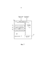
Ниже, со ссылкой на фиг. 5, будет описан пример аудиодекодера преобразования, выполненного с возможностью выполнения описанной выше процедуры для поддержки расширения полосы частот, BWE, гармонического аудиосигнала. Деаудиокодер преобразования может представлять собой, например, декодер MDCT или другой декодер. Below, with reference to FIG. 5, an example of an audio conversion decoder decoder configured to perform the above procedure to support bandwidth extension, BWE, harmonic audio signal will be described. The deaudio transform encoder may be, for example, an MDCT decoder or other decoder.
Декодер 501 преобразования аудиоданных представлен, как связывающийся с другими объектами через модуль 502 передачи данных. Часть декодера преобразования аудиоданных, выполненная с возможностью обеспечения рабочей характеристики описанной выше процедуры, представлена, как компоновка 500, окруженная пунктирной линией. Деаудиокодер преобразования может дополнительно содержать другие функциональные модули 516, такие как, например, функциональные модули, обеспечивающие регулярные функции декодера и BWE, и может дополнительно содержать один или больше модулей 514 сохранения.The audio
Декодер 501 преобразования аудиоданных и/или компоновка 500 могут быть воплощены, например, с использованием одного или больше: процессора или микропроцессора и соответствующих программных средств, с соответствующим их сохранением, программируемого логического устройства (PLD) или другого электронного компонента (компонентов).The audio
Деаудиокодер преобразования, как предполагается, содержит функциональные модули, для получения адекватных параметров, предоставляемых из объекта кодирования. Коэффициент смешивания с шумами представляет собой новый параметр для получения по сравнению с предшествующим уровнем техники. Таким образом, декодер должен быть выполнен так, чтобы один или больше коэффициентов смешения с шумами могут быть получен, когда требуется такое свойство. Деаудиокодер преобразования может быть описан и воплощен, как содержащий модуль приема, выполненный с возможностью приема множества значений усиления, ассоциированных с полосой b частот и множества соседних полос частот для полосы b; и, возможно, коэффициента смешивания шумов. Такой модуль приема, однако, не показан в явном виде на фиг. 5. The conversion deaudio coder is supposed to contain functional modules to obtain adequate parameters provided from the encoding object. The noise mixing factor is a new parameter to obtain compared with the prior art. Thus, the decoder must be designed so that one or more noise mixing ratios can be obtained when such a property is required. A conversion deaudio coder can be described and implemented as comprising a receiving module configured to receive a plurality of gain values associated with a frequency band b and a plurality of adjacent frequency bands for a band b; and possibly a noise mixing factor. Such a reception module, however, is not explicitly shown in FIG. five.
Деаудиокодер преобразования содержит модуль определения, в качестве альтернативы, обозначенный, как модуль 504 детектирования пика, который выполнен с возможностью определения и представления, какие полосы области спектра BWE содержат пик и какие полосы не содержат пик. То есть, модуль определения выполнен с возможностью определения, содержит или нет спектральный пик реконструированная соответствующая полоса b’ частот области частот расширенной полосы частот. Кроме того, аудиодекодер преобразования может содержать модуль 506 модификации усиления, который выполнен с возможностью модификации усиления, ассоциированного с полосой, в зависимости от того, содержит ли полоса пик или нет. Если полоса содержит пик, модифицированный коэффициент усиления рассчитывают, как взвешенную сумму, например, среднее или медианное значение от (оригинальных) значений усиления множества полос, расположенных рядом с рассматриваемой полосой, включая в себя усиление данной полосы.The conversion deaudio coder comprises a determination module, alternatively designated as a
Деаудиокодер преобразования может дополнительно содержать модуль 508 применения коэффициента усиления, выполненный с возможностью применения или установки модифицированного коэффициента усиления в соответствующих полосах спектра BWE. Таким образом, модуль применения усиления выполнен с возможностью установки значения усиления, ассоциированного с реконструированной полосой b’ частот для первого значения на основе принятого множества значений усиления, когда реконструированная полоса b’ частот содержит, по меньшей мере, один спектральный пик, и для установки значения усиления, ассоциированного с реконструированной полосой b’ частот, во второе значение на основе принятого множества значений усиления, когда реконструированный диапазон частот b’ не содержит спектральный пик, где второе значение меньше, чем или равно первому значению. Таким образом, обеспечивается перевод значений усиления в соответствии с положениями пиков области частоты расширенной полосы частот.The conversion deaudio coder may further comprise a
В качестве альтернативы, если возможно без модификации, применяемая функция может быть предусмотрена с использованием (обычной) дополнительной функции 516, только в случае, когда применяемые коэффициенты усиления не являются оригинальными коэффициентами усиления, но модифицированными коэффициентами усиления. Кроме того, деаудиокодер преобразования может содержать модуль 510 смешивания шумов, выполненный с возможностью смешивания коэффициентов части BWE спектра с шумами, например, из кодовой книги, на основе одного или больше коэффициентов шумов или параметров, предоставляемых кодером аудиосигнала.Alternatively, if possible without modification, the function used may be provided using the (normal)
Пример процедуры кодера Example encoder procedure
Пример процедуры, выполняемой в кодере для поддержки расширения полосы частот, BWE, гармонического аудиосигнала будет описан ниже со ссылкой на фиг. 6.Эта процедура пригодна для использования при преобразовании аудиокодера, такого как, например, кодер MDCT или другой кодер. Как было упомянуто выше, предполагается, что аудиосигнал, прежде всего, представляет собой музыку, но может также, в качестве альтернативы, содержать, например, речь.An example of a procedure performed in an encoder to support bandwidth extension, BWE, harmonic audio will be described below with reference to FIG. 6. This procedure is suitable for use in converting an audio encoder, such as, for example, an MDCT encoder or other encoder. As mentioned above, it is assumed that the audio signal is primarily music, but may also, alternatively, comprise, for example, speech.
Процедура, описанная ниже, относится к частям процедуры кодирования, которая отклоняется от обычного кодирования гармонического аудиосигнала, из-за использования кодера преобразования. Таким образом, действия, описанные ниже, представляют собой необязательное добавление к предоставлению коэффициентов преобразования и коэффициентов усиления и т.д., для нижней части спектра и вывода коэффициентов усиления для полос верхней части спектра (части, которая конструируется BWE на стороне декодера).The procedure described below relates to parts of an encoding procedure that deviates from conventional encoding of a harmonic audio signal due to the use of a transform encoder. Thus, the steps described below are an optional addition to the provision of conversion and gain factors, etc., for the lower part of the spectrum and output of the gain factors for the bands of the upper part of the spectrum (the part that is constructed by the BWE on the decoder side).
Энергию пика, относящуюся к верхней части частотного спектра, определяют в действии 602. Кроме того, энергетический уровень шумов, относящийся к верхней части частотного спектра, определяют в действии 603. Например, среднюю энергию пика ![]()
![]()
![]()
![]()
Пример кодераEncoder example
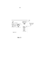
Ниже, со ссылкой на фиг. 7, будет описан пример аудиодекодера преобразования, выполненный с возможностью выполнения описанной выше процедуры для поддержки расширения полосы частот, BWE, гармонического аудиосигнала. Аудиодекодер преобразования может представлять собой, например, декодер MDCT или другой декодер. Below, with reference to FIG. 7, an example of a conversion audio decoder will be described, configured to perform the above procedure to support bandwidth extension, BWE, harmonic audio signal. The conversion audio decoder may be, for example, an MDCT decoder or other decoder.
Аудиодекодер преобразования 701 иллюстрируется, как связывающийся с другими объектами через модуль 702 передачи данных. Часть преобразования аудиодекодера, которая выполнена с возможностью обеспечения рабочих характеристик описанной выше процедуры, представлена, как компоновка 700, окруженная пунктирной линией. Аудиодекодер преобразования может дополнительно содержать другие функциональные модули 712, такие как, например, функциональные модули, обеспечивающие регулярные функции кодера, и может дополнительно содержать один или больше модулей 710 сохранения.The audio decoder 701 conversion is illustrated as communicating with other objects through the
Аудиокодер 701 преобразования и/или компоновка 700 могут быть воплощены, например, с использованием одного или больше: процессора или микропроцессора, и соответствующих программных средств сохранения для него, программируемого логического устройства (PLD) или другого электронного компонента (компонентов).The audio encoder 701 conversion and / or
Аудиокодер преобразования может содержать модуль 704 определения, который выполнен с возможностью определения пиковой энергии и энергии уровня шумов в верхней части спектра. Кроме того, аудиокодер преобразования может содержать модуль 706 коэффициента шумов, который выполнен с возможностью расчета одного или больше коэффициентов смешивания шумов для всей верхней части спектра или его участков. Аудиодекодер преобразования может дополнительно содержать модуль 708 предоставления, выполненный с возможностью предоставления рассчитанных коэффициентов смешивания шумов для использования в кодере. Предоставление может содержать, например, простой вывод расчетных коэффициентов смешивания шумов на выход, и/или, например, передачу коэффициентов в декодер.The audio conversion encoder may comprise a
Пример компоновкиLayout Example
На фиг. 8 схематично показан вариант осуществления компоновки 800, пригодной для использования в аудиодекодере преобразования, который может также представлять собой альтернативный способ раскрытия варианта осуществления компоновки для использования в аудиодекодере преобразования, представленном на фиг. 5. В состав компоновки 800 входит модуль 806 обработки, например, с DSP (цифровой сигнальный процессор). Модуль 806 обработки может представлять собой одиночный модуль или множество модулей для выполнения разных этапов процедур, описанных здесь. Компоновка 800 также может содержать модуль 802 ввода для приема сигналов, таких как декодированная нижняя часть спектра, коэффициенты усиления для всего спектра и коэффициент (коэффициенты) для смешивания шумов (сравни с кодером: верхняя часть гармонического спектра), и модуль 804 вывода для вывода сигнала (сигналов), такого как модифицированные коэффициенты усиления и/или полный спектр (сравни с кодером: коэффициенты смешивания шумов). Модуль 802 ввода и модуль 804 вывода могут быть выполнены, как одно из аппаратных средств компоновки. In FIG. 8 schematically shows an embodiment of an
Кроме того, компоновка 800 содержит, по меньшей мере, один компьютерный программный продукт 808 в форме энергонезависимого или энергозависимого запоминающего устройства, например, EEPROM, запоминающего устройства флэш и привода жесткого диска. Компьютерный программный продукт 808 содержит компьютерную программу 810, которая содержит средство кода, которое при его работе в модуле 806 обработки в компоновке 800 обеспечивает выполнение действий процедуры компоновкой и/или аудиокодером преобразования, описанным выше со ссылкой на фиг. 4.In addition, the
Следовательно, в описанных примерных вариантах осуществления, средство кода в компьютерной программе 810 компоновки 800 может содержать, получение модуля 810 для получения информации, относящейся к нижней части аудиоспектра, и коэффициента усиления, относящегося ко всему аудиоспектру. Кроме того, могут быть получены коэффициенты шумов, относящиеся к верхней части аудиоспектра. Компьютерная программа может содержать модуль 810b детектирования, предназначенный для детектирования и обозначения, содержат ли полосы реконструированных полос b полосы частот области с расширенной полосой частот спектральный пик, или нет. Компьютерная программа 810 может дополнительно содержать модуль 810c модификации усиления, предназначенный для модификации усиления, ассоциированный с полосами частот верхний, реконструируемой части спектра. Компьютерная программа 810 может дополнительно содержать модуль 810d применения усиления, предназначенный для применения модифицированного усиления для соответствующих полос верхней части спектра. Кроме того, компьютерная программа 810 может содержать модуль 810d для смешивания шумов, для смешивания верхней части спектра с шумами на основе принятых коэффициентов смешивания шумов.Therefore, in the described exemplary embodiments, the code means in the
Компьютерная программа 810 выполнена в форме компьютерного программного кода, структурированного в компьютерные программные модули. Модули 810a-d, по существу, выполняют действия потока, иллюстрируемого на фиг. 4a или 4b, для эмуляции компоновки 500, представленной на фиг. 5. Другими словами, когда разные модули 810a-d работают в модуле 806 обработки, они соответствуют, по меньшей мере, модулям 504-510 по фиг. 5.
Хотя средство кода в варианте осуществления, раскрытом выше со ссылкой на фиг. 8, воплощено, как компьютерные программные модули, которые при их работе в модуле обработки обеспечивают выполнение компоновкой и/или кодером преобразования аудиоданных этапов, описанных выше, совместно с фигурами, упомянутыми выше, по меньшей мере, одно средство кода, в альтернативных вариантах осуществления, может быть воплощено, как, по меньшей мере, часть аппаратных схем.Although the code means in the embodiment disclosed above with reference to FIG. 8 is embodied as computer program modules that, when operated in a processing module, make it possible for the layout and / or encoder to convert the audio data of the steps described above, together with the figures mentioned above, at least one code means, in alternative embodiments, can be embodied as at least part of the hardware circuits.
Аналогичным образом, примерный вариант осуществления, содержащий компьютерные программные модули, может быть описан для соответствующей компоновки при преобразовании аудиокодера, представленного на фиг. 7.Similarly, an exemplary embodiment comprising computer program modules may be described for the corresponding layout when converting the audio encoder shown in FIG. 7.
В то время, как предложенная технология была описана со ссылкой на конкретные примерные варианты осуществления, общее описание предназначено только для иллюстрации концепции и его не следует рассматривать, как ограничение объема представленного здесь решения. Различные функции представленных выше примеров вариантов осуществления могут быть скомбинированы разными способами, в соответствии с потребностью, требованиями или предпочтениями.While the proposed technology has been described with reference to specific exemplary embodiments, the general description is intended only to illustrate the concept and should not be construed as limiting the scope of the solution presented here. The various functions of the above examples of embodiments can be combined in different ways, according to need, requirements or preferences.
Описанное выше решение может использоваться каждый раз, когда аудиокодеки применяют, например, в устройствах, таких как мобильные терминалы, планшетные компьютеры, компьютеры, смартфоны и т.д.The solution described above can be used every time audio codecs are used, for example, in devices such as mobile terminals, tablet computers, computers, smartphones, etc.
Следует понимать, что выбор взаимодействующих блоков или модулей, а также наименования этих модулей представлены только с целью примера, и узлы, соответствующие для исполнения любого из способов, описанных выше, могут быть сконфигурированы в виде множества альтернативных способов, для того, чтобы обеспечить возможность исполнения предполагаемых действий по обработке. It should be understood that the choice of interacting blocks or modules, as well as the names of these modules are presented only for the purpose of example, and the nodes corresponding to the execution of any of the methods described above can be configured in the form of many alternative methods, in order to provide the possibility of execution intended processing actions.
Также следует отметить, что блоки или модули, описанные в данном раскрытии, следует рассматривать, как логические объекты, и не обязательно, как отдельные физические объекты. Хотя представленное выше описание содержит много конкретных терминов, их не следует рассматривать, как ограничение объема данного раскрытия, в просто, как предоставляющее иллюстрацию некоторых из предпочтительных в настоящее время вариантов осуществления предложенной здесь технологии. Следует понимать, что объем технологии, предложенной здесь, полностью охватывает другие варианты осуществления, которые могут стать очевидными для специалиста в данной области техники, и что объем данного раскрытия, соответственно, не должен быть ограничен ими. Предполагается, что ссылка на элемент в единственном числе не исключает значение "один и только один", если только в явном виде не будет указано такое, но скорее "один или больше". Все структурные и функциональные эквиваленты для элементов описанных выше вариантов осуществления, которые известны для специалистов в данной области техники, в явном виде представлены здесь по ссылке и предназначены для охвата настоящего описания. Кроме того, нет необходимости, чтобы устройство или способ было направлено на решение каждой проблемы с использованием представленной здесь технологии.It should also be noted that the blocks or modules described in this disclosure should be considered as logical objects, and not necessarily, as separate physical objects. Although the above description contains many specific terms, they should not be construed as limiting the scope of this disclosure, simply as providing an illustration of some of the currently preferred embodiments of the technology proposed herein. It should be understood that the scope of the technology proposed here, fully covers other options for implementation, which may become apparent to a person skilled in the art, and that the scope of this disclosure, respectively, should not be limited to them. It is assumed that a reference to an element in the singular does not exclude the value “one and only one”, unless explicitly stated, but rather “one or more”. All structural and functional equivalents for elements of the above embodiments that are known to those skilled in the art are expressly presented herein by reference and are intended to cover the present description. In addition, there is no need for the device or method to address each problem using the technology presented here.
В представленном описании, с целью пояснения и не для ограничений, конкретные детали представлены, как конкретная архитектура, интерфейсы, технологии и т.д., для предоставления полного понимания предложенной технологии. Однако для специалиста в данной области техники будет понятно, что предложенная технология может быть выполнена на практике в других вариантах осуществления, которые выходят за пределы этих конкретных деталей. Таким образом, для специалиста в данной области техники будет возможно разработать различные компоновки, которые, хотя и не были в явном виде описаны или представлены здесь, воплощают принципы предложенной технологии. В некоторых случаях, подробное описание хорошо известных устройств, схем и способов исключено, чтобы не усложнять описание предложенной технологии ненужными деталями. Все представленные здесь утверждения, описывающие принципы, аспекты и варианты осуществления предложенной технологии, а также конкретные ее примеры, предназначены для охвата, как структурных, так и функциональных ее эквивалентов. Кроме того, предполагается, что такие эквиваленты включают в себя, как известные в настоящее время эквиваленты, а также эквиваленты, которые будут разработаны в будущем, например, любые разработанные элементы, которые выполняют ту же функцию, независимо от структуры. In the presented description, for the purpose of explanation and not for limitation, specific details are presented as specific architecture, interfaces, technologies, etc., to provide a complete understanding of the proposed technology. However, it will be understood by those skilled in the art that the proposed technology can be practiced in other embodiments that go beyond these specific details. Thus, it will be possible for a person skilled in the art to develop various arrangements that, although not explicitly described or presented here, embody the principles of the proposed technology. In some cases, a detailed description of well-known devices, circuits, and methods is excluded so as not to complicate the description of the proposed technology with unnecessary details. All statements presented here, describing the principles, aspects and options for implementing the proposed technology, as well as specific examples thereof, are intended to cover both structural and functional equivalents thereof. In addition, it is contemplated that such equivalents include, as currently known, equivalents as well as equivalents that will be developed in the future, for example, any developed elements that perform the same function, regardless of structure.
Таким образом, например, для специалиста в данной области техники следует понимать, что блок-схемы, представленные здесь, могут представлять концептуальные виды иллюстративной схемы или другие функциональные блоки, воплощающие принципы технологии. Аналогично, следует понимать, что любые блок-схемы последовательности операций, диаграммы перехода состояний, псевдокоды и другие представленные различные процессы, могут быть представлены, по существу, на считываемом компьютером носителе информации и могут выполняться компьютером или процессором, независимо от того, показан или нет такой компьютер, или процессор в явном виде. Thus, for example, one skilled in the art should understand that the block diagrams presented here may represent conceptual views of an illustrative circuit or other functional blocks embodying the principles of the technology. Similarly, it should be understood that any flowcharts, state transition diagrams, pseudo-codes, and other various processes represented can be represented essentially on a computer-readable storage medium and can be executed by a computer or processor, whether or not shown such a computer or processor explicitly.
Функции различных элементов, включающих в себя функциональные блоки, включающие в себя, но не ограниченные помеченными или описанными, как "функциональный модуль", "процессор" или "контроллер", могут быть предусмотрены путем использования аппаратных средств, таких как аппаратные средства в виде схемы и/или аппаратные средства, выполненные с возможностью исполнения программного обеспечения в форме кодированных инструкций, сохраняемых на считываемом компьютером носителе информации. Таким образом, такие функции и представленные функциональные блоки следует понимать, как воплощенные либо в виде аппаратных средств, и/или воплощенные в компьютере, и, таким образом, воплощенные в машине. The functions of various elements, including functional blocks, including but not limited to those labeled or described as a “function module”, “processor” or “controller”, may be provided by using hardware such as hardware in circuit form and / or hardware configured to execute the software in the form of encoded instructions stored on a computer-readable storage medium. Thus, such functions and the presented functional blocks should be understood as embodied either in the form of hardware, and / or embodied in a computer, and thus embodied in a machine.
В терминах воплощения в виде аппаратных средств функциональные блоки могут включать в себя или могут охватывать, без ограничений, аппаратные средства цифрового сигнального процессора (DSP), процессора с уменьшенным набором инструкций, аппаратные (например, цифровые или аналоговые) схемы, включающие в себя, но без ограничений, специализированную интегральную микросхему (микросхемы) (ASIC), и (в случае необходимости) конечные автоматы, выполненные с возможностью выполнения таких функций.In terms of a hardware embodiment, the functional blocks may include, or may include, without limitation, the hardware of a digital signal processor (DSP), a processor with a reduced instruction set, hardware (e.g., digital or analog) circuits, including but without limitation, a specialized integrated circuit (s) (ASIC), and (if necessary) finite state machines made with the ability to perform such functions.
СокращенияAbbreviations
BWE Расширение полосы частотBWE Bandwidth Extension
DFT Дискретное преобразование ФурьеDFT Discrete Fourier Transform
DCT Дискретное косинусное преобразование DCT Discrete Cosine Transform
MDCT Модифицированное дискретное косинусное преобразование MDCT Modified Discrete Cosine Transform
Claims (29)
Applications Claiming Priority (2)
| Application Number | Priority Date | Filing Date | Title |
|---|---|---|---|
| US201261617175P | 2012-03-29 | 2012-03-29 | |
| US61/617,175 | 2012-03-29 |
Related Parent Applications (1)
| Application Number | Title | Priority Date | Filing Date |
|---|---|---|---|
| RU2014143463A Division RU2610293C2 (en) | 2012-03-29 | 2012-12-21 | Harmonic audio frequency band expansion |
Publications (1)
| Publication Number | Publication Date |
|---|---|
| RU2725416C1 true RU2725416C1 (en) | 2020-07-02 |
Family
ID=47666458
Family Applications (2)
| Application Number | Title | Priority Date | Filing Date |
|---|---|---|---|
| RU2017103506A RU2725416C1 (en) | 2012-03-29 | 2012-12-21 | Broadband of harmonic audio signal |
| RU2014143463A RU2610293C2 (en) | 2012-03-29 | 2012-12-21 | Harmonic audio frequency band expansion |
Family Applications After (1)
| Application Number | Title | Priority Date | Filing Date |
|---|---|---|---|
| RU2014143463A RU2610293C2 (en) | 2012-03-29 | 2012-12-21 | Harmonic audio frequency band expansion |
Country Status (12)
| Country | Link |
|---|---|
| US (3) | US9437202B2 (en) |
| EP (1) | EP2831875B1 (en) |
| JP (4) | JP5945626B2 (en) |
| KR (2) | KR101704482B1 (en) |
| CN (2) | CN106847303B (en) |
| ES (1) | ES2561603T3 (en) |
| HU (1) | HUE028238T2 (en) |
| MY (2) | MY197538A (en) |
| PL (1) | PL2831875T3 (en) |
| RU (2) | RU2725416C1 (en) |
| WO (1) | WO2013147668A1 (en) |
| ZA (1) | ZA201406340B (en) |
Families Citing this family (11)
| Publication number | Priority date | Publication date | Assignee | Title |
|---|---|---|---|---|
| KR101704482B1 (en) | 2012-03-29 | 2017-02-09 | 텔레폰악티에볼라겟엘엠에릭슨(펍) | Bandwidth extension of harmonic audio signal |
| RU2611017C2 (en) * | 2012-03-29 | 2017-02-17 | Телефонактиеболагет Л М Эрикссон (Пабл) | Transform encoding/decoding of harmonic audio signals |
| FI3547261T3 (en) * | 2012-03-29 | 2023-09-26 | Ericsson Telefon Ab L M | Vector quantizer |
| EP2830054A1 (en) | 2013-07-22 | 2015-01-28 | Fraunhofer Gesellschaft zur Förderung der angewandten Forschung e.V. | Audio encoder, audio decoder and related methods using two-channel processing within an intelligent gap filling framework |
| US9666202B2 (en) | 2013-09-10 | 2017-05-30 | Huawei Technologies Co., Ltd. | Adaptive bandwidth extension and apparatus for the same |
| US10083708B2 (en) * | 2013-10-11 | 2018-09-25 | Qualcomm Incorporated | Estimation of mixing factors to generate high-band excitation signal |
| US20150149157A1 (en) * | 2013-11-22 | 2015-05-28 | Qualcomm Incorporated | Frequency domain gain shape estimation |
| CN105900170B (en) * | 2014-01-07 | 2020-03-10 | 哈曼国际工业有限公司 | Signal quality based enhancement and compensation of compressed audio signals |
| CN110619884B (en) * | 2014-03-14 | 2023-03-07 | 瑞典爱立信有限公司 | Audio encoding method and apparatus |
| ES2808997T3 (en) * | 2016-04-12 | 2021-03-02 | Fraunhofer Ges Forschung | Audio encoder for encoding an audio signal, method for encoding an audio signal and computer program in consideration of a spectral region of the peak detected in a higher frequency band |
| US10839814B2 (en) * | 2017-10-05 | 2020-11-17 | Qualcomm Incorporated | Encoding or decoding of audio signals |
Citations (8)
| Publication number | Priority date | Publication date | Assignee | Title |
|---|---|---|---|---|
| WO2000045379A2 (en) * | 1999-01-27 | 2000-08-03 | Coding Technologies Sweden Ab | Enhancing perceptual performance of sbr and related hfr coding methods by adaptive noise-floor addition and noise substitution limiting |
| WO2011000780A1 (en) * | 2009-06-29 | 2011-01-06 | Fraunhofer-Gesellschaft Zur Foerderung Der Angewandten Forschung E.V. | Bandwidth extension encoder, bandwidth extension decoder and phase vocoder |
| RU2409874C9 (en) * | 2005-11-04 | 2011-05-20 | Нокиа Корпорейшн | Audio signal compression |
| WO2011062538A1 (en) * | 2009-11-19 | 2011-05-26 | Telefonaktiebolaget Lm Ericsson (Publ) | Bandwidth extension of a low band audio signal |
| WO2011129305A1 (en) * | 2010-04-13 | 2011-10-20 | ソニー株式会社 | Signal processing device and method, encoding device and method, decoding device and method, and program |
| RU2010126497A (en) * | 2007-11-29 | 2012-01-10 | Моторола, Инк. (US) | METHOD AND DEVICE FOR EXPANDING THE WIDTH OF THE AUDIO BAND |
| WO2012017621A1 (en) * | 2010-08-03 | 2012-02-09 | Sony Corporation | Signal processing apparatus and method, and program |
| RU2010137104A (en) * | 2008-02-07 | 2012-03-20 | Моторола, Инк. (US) | METHOD AND DEVICE FOR ESTIMATING HIGH FREQUENCY BAND ENERGY IN THE FREQUENCY BAND EXTENSION SYSTEM |
Family Cites Families (40)
| Publication number | Priority date | Publication date | Assignee | Title |
|---|---|---|---|---|
| US5490172A (en) * | 1994-07-05 | 1996-02-06 | Airnet Communications Corporation | Reducing peak-to-average variance of a composite transmitted signal via out-of-band artifact signaling |
| US20020128839A1 (en) * | 2001-01-12 | 2002-09-12 | Ulf Lindgren | Speech bandwidth extension |
| EP1701340B1 (en) * | 2001-11-14 | 2012-08-29 | Panasonic Corporation | Decoding device, method and program |
| DE60202881T2 (en) * | 2001-11-29 | 2006-01-19 | Coding Technologies Ab | RECONSTRUCTION OF HIGH-FREQUENCY COMPONENTS |
| DE60303689T2 (en) * | 2002-09-19 | 2006-10-19 | Matsushita Electric Industrial Co., Ltd., Kadoma | AUDIO DECODING DEVICE AND METHOD |
| CN1748443B (en) * | 2003-03-04 | 2010-09-22 | 诺基亚有限公司 | Support of a multichannel audio extension |
| JP4899359B2 (en) * | 2005-07-11 | 2012-03-21 | ソニー株式会社 | Signal encoding apparatus and method, signal decoding apparatus and method, program, and recording medium |
| CN1960351A (en) * | 2005-10-31 | 2007-05-09 | 华为技术有限公司 | Terminal information transmission method, and terminal transmitter in wireless communication system |
| EP1943643B1 (en) | 2005-11-04 | 2019-10-09 | Nokia Technologies Oy | Audio compression |
| US7546237B2 (en) * | 2005-12-23 | 2009-06-09 | Qnx Software Systems (Wavemakers), Inc. | Bandwidth extension of narrowband speech |
| KR20070115637A (en) * | 2006-06-03 | 2007-12-06 | 삼성전자주식회사 | Method and apparatus for bandwidth extension encoding and decoding |
| CN101089951B (en) * | 2006-06-16 | 2011-08-31 | 北京天籁传音数字技术有限公司 | Band spreading coding method and device and decode method and device |
| DE102006047197B3 (en) * | 2006-07-31 | 2008-01-31 | Fraunhofer-Gesellschaft zur Förderung der angewandten Forschung e.V. | Device for processing realistic sub-band signal of multiple realistic sub-band signals, has weigher for weighing sub-band signal with weighing factor that is specified for sub-band signal around subband-signal to hold weight |
| CN101140759B (en) * | 2006-09-08 | 2010-05-12 | 华为技术有限公司 | Band-width spreading method and system for voice or audio signal |
| DE102008015702B4 (en) | 2008-01-31 | 2010-03-11 | Fraunhofer-Gesellschaft zur Förderung der angewandten Forschung e.V. | Apparatus and method for bandwidth expansion of an audio signal |
| JP5108960B2 (en) * | 2008-03-04 | 2012-12-26 | エルジー エレクトロニクス インコーポレイティド | Audio signal processing method and apparatus |
| CN101552005A (en) * | 2008-04-03 | 2009-10-07 | 华为技术有限公司 | Encoding method, decoding method, system and device |
| US8149955B2 (en) * | 2008-06-30 | 2012-04-03 | Telefonaktiebolaget L M Ericsson (Publ) | Single ended multiband feedback linearized RF amplifier and mixer with DC-offset and IM2 suppression feedback loop |
| EP2144230A1 (en) * | 2008-07-11 | 2010-01-13 | Fraunhofer-Gesellschaft zur Förderung der angewandten Forschung e.V. | Low bitrate audio encoding/decoding scheme having cascaded switches |
| JP5325293B2 (en) * | 2008-07-11 | 2013-10-23 | フラウンホッファー−ゲゼルシャフト ツァ フェルダールング デァ アンゲヴァンテン フォアシュンク エー.ファオ | Apparatus and method for decoding an encoded audio signal |
| CN103000186B (en) * | 2008-07-11 | 2015-01-14 | 弗劳恩霍夫应用研究促进协会 | Time warp activation signal provider and audio signal encoder using a time warp activation signal |
| EP2146344B1 (en) * | 2008-07-17 | 2016-07-06 | Fraunhofer-Gesellschaft zur Förderung der angewandten Forschung e.V. | Audio encoding/decoding scheme having a switchable bypass |
| US8463412B2 (en) * | 2008-08-21 | 2013-06-11 | Motorola Mobility Llc | Method and apparatus to facilitate determining signal bounding frequencies |
| JP4818335B2 (en) | 2008-08-29 | 2011-11-16 | 株式会社東芝 | Signal band expander |
| US8515747B2 (en) * | 2008-09-06 | 2013-08-20 | Huawei Technologies Co., Ltd. | Spectrum harmonic/noise sharpness control |
| WO2010028297A1 (en) * | 2008-09-06 | 2010-03-11 | GH Innovation, Inc. | Selective bandwidth extension |
| US8463599B2 (en) * | 2009-02-04 | 2013-06-11 | Motorola Mobility Llc | Bandwidth extension method and apparatus for a modified discrete cosine transform audio coder |
| ATE527759T1 (en) * | 2009-05-11 | 2011-10-15 | Harman Becker Automotive Sys | SIGNAL ANALYSIS FOR IMPROVED DETECTION OF NOISE FROM AN ADJACENT CHANNEL |
| RU2547220C2 (en) * | 2009-10-21 | 2015-04-10 | Фраунхофер-Гезелльшафт цур Фёрдерунг дер ангевандтен Форшунг Е.Ф. | Apparatus and method of generating high frequency audio signal using adaptive oversampling |
| CN102044250B (en) * | 2009-10-23 | 2012-06-27 | 华为技术有限公司 | Band spreading method and apparatus |
| EP2502230B1 (en) * | 2009-11-19 | 2014-05-21 | Telefonaktiebolaget L M Ericsson (PUBL) | Improved excitation signal bandwidth extension |
| PL2581905T3 (en) * | 2010-06-09 | 2016-06-30 | Panasonic Ip Corp America | Bandwidth extension method, bandwidth extension apparatus, program, integrated circuit, and audio decoding apparatus |
| DK2975611T3 (en) * | 2011-03-10 | 2018-04-03 | Ericsson Telefon Ab L M | FILLING OF UNCODED SUBVECTORS IN TRANSFORM CODED AUDIO SIGNALS |
| ES2540051T3 (en) * | 2011-04-15 | 2015-07-08 | Telefonaktiebolaget Lm Ericsson (Publ) | Method and decoder for attenuation of reconstructed signal regions with low accuracy |
| CN102223341B (en) * | 2011-06-21 | 2013-06-26 | 西安电子科技大学 | Method for reducing peak-to-average power ratio of frequency domain forming OFDM (Orthogonal Frequency Division Multiplexing) without bandwidth expansion |
| JP5969614B2 (en) * | 2011-09-28 | 2016-08-17 | エルジー エレクトロニクス インコーポレイティド | Speech signal encoding method and speech signal decoding method |
| EP2791937B1 (en) * | 2011-11-02 | 2016-06-08 | Telefonaktiebolaget LM Ericsson (publ) | Generation of a high band extension of a bandwidth extended audio signal |
| KR101704482B1 (en) | 2012-03-29 | 2017-02-09 | 텔레폰악티에볼라겟엘엠에릭슨(펍) | Bandwidth extension of harmonic audio signal |
| EP2682941A1 (en) * | 2012-07-02 | 2014-01-08 | Technische Universität Ilmenau | Device, method and computer program for freely selectable frequency shifts in the sub-band domain |
| EP2830054A1 (en) * | 2013-07-22 | 2015-01-28 | Fraunhofer Gesellschaft zur Förderung der angewandten Forschung e.V. | Audio encoder, audio decoder and related methods using two-channel processing within an intelligent gap filling framework |
-
2012
- 2012-12-21 KR KR1020147029750A patent/KR101704482B1/en active IP Right Review Request
- 2012-12-21 RU RU2017103506A patent/RU2725416C1/en active
- 2012-12-21 EP EP12821332.9A patent/EP2831875B1/en active Active
- 2012-12-21 HU HUE12821332A patent/HUE028238T2/en unknown
- 2012-12-21 CN CN201710139608.6A patent/CN106847303B/en active Active
- 2012-12-21 US US14/388,052 patent/US9437202B2/en active Active
- 2012-12-21 MY MYPI2018001313A patent/MY197538A/en unknown
- 2012-12-21 ES ES12821332.9T patent/ES2561603T3/en active Active
- 2012-12-21 KR KR1020177002815A patent/KR101740219B1/en active IP Right Grant
- 2012-12-21 PL PL12821332T patent/PL2831875T3/en unknown
- 2012-12-21 WO PCT/SE2012/051470 patent/WO2013147668A1/en active Application Filing
- 2012-12-21 CN CN201280071983.7A patent/CN104221082B/en active Active
- 2012-12-21 MY MYPI2014702776A patent/MY167474A/en unknown
- 2012-12-21 RU RU2014143463A patent/RU2610293C2/en active
- 2012-12-21 JP JP2015503154A patent/JP5945626B2/en active Active
-
2014
- 2014-08-28 ZA ZA2014/06340A patent/ZA201406340B/en unknown
-
2016
- 2016-05-30 JP JP2016107734A patent/JP6251773B2/en active Active
- 2016-07-27 US US15/220,756 patent/US9626978B2/en active Active
-
2017
- 2017-03-06 US US15/450,271 patent/US10002617B2/en active Active
- 2017-10-05 JP JP2017195350A patent/JP6474874B2/en active Active
- 2017-11-27 JP JP2017227001A patent/JP6474877B2/en active Active
Patent Citations (8)
| Publication number | Priority date | Publication date | Assignee | Title |
|---|---|---|---|---|
| WO2000045379A2 (en) * | 1999-01-27 | 2000-08-03 | Coding Technologies Sweden Ab | Enhancing perceptual performance of sbr and related hfr coding methods by adaptive noise-floor addition and noise substitution limiting |
| RU2409874C9 (en) * | 2005-11-04 | 2011-05-20 | Нокиа Корпорейшн | Audio signal compression |
| RU2010126497A (en) * | 2007-11-29 | 2012-01-10 | Моторола, Инк. (US) | METHOD AND DEVICE FOR EXPANDING THE WIDTH OF THE AUDIO BAND |
| RU2010137104A (en) * | 2008-02-07 | 2012-03-20 | Моторола, Инк. (US) | METHOD AND DEVICE FOR ESTIMATING HIGH FREQUENCY BAND ENERGY IN THE FREQUENCY BAND EXTENSION SYSTEM |
| WO2011000780A1 (en) * | 2009-06-29 | 2011-01-06 | Fraunhofer-Gesellschaft Zur Foerderung Der Angewandten Forschung E.V. | Bandwidth extension encoder, bandwidth extension decoder and phase vocoder |
| WO2011062538A1 (en) * | 2009-11-19 | 2011-05-26 | Telefonaktiebolaget Lm Ericsson (Publ) | Bandwidth extension of a low band audio signal |
| WO2011129305A1 (en) * | 2010-04-13 | 2011-10-20 | ソニー株式会社 | Signal processing device and method, encoding device and method, decoding device and method, and program |
| WO2012017621A1 (en) * | 2010-08-03 | 2012-02-09 | Sony Corporation | Signal processing apparatus and method, and program |
Also Published As
| Publication number | Publication date |
|---|---|
| ES2561603T3 (en) | 2016-02-29 |
| US20170178638A1 (en) | 2017-06-22 |
| CN106847303A (en) | 2017-06-13 |
| PL2831875T3 (en) | 2016-05-31 |
| JP6474877B2 (en) | 2019-02-27 |
| KR20170016033A (en) | 2017-02-10 |
| JP2016189012A (en) | 2016-11-04 |
| EP2831875A1 (en) | 2015-02-04 |
| WO2013147668A1 (en) | 2013-10-03 |
| CN106847303B (en) | 2020-10-13 |
| KR101704482B1 (en) | 2017-02-09 |
| JP6251773B2 (en) | 2017-12-20 |
| EP2831875B1 (en) | 2015-12-16 |
| US9626978B2 (en) | 2017-04-18 |
| ZA201406340B (en) | 2016-06-29 |
| RU2014143463A (en) | 2016-05-20 |
| US20150088527A1 (en) | 2015-03-26 |
| KR101740219B1 (en) | 2017-05-25 |
| CN104221082B (en) | 2017-03-08 |
| JP2018041088A (en) | 2018-03-15 |
| CN104221082A (en) | 2014-12-17 |
| RU2610293C2 (en) | 2017-02-08 |
| US20160336016A1 (en) | 2016-11-17 |
| US10002617B2 (en) | 2018-06-19 |
| MY167474A (en) | 2018-08-29 |
| KR20140139582A (en) | 2014-12-05 |
| HUE028238T2 (en) | 2016-12-28 |
| JP6474874B2 (en) | 2019-02-27 |
| JP5945626B2 (en) | 2016-07-05 |
| JP2018072846A (en) | 2018-05-10 |
| US9437202B2 (en) | 2016-09-06 |
| MY197538A (en) | 2023-06-22 |
| JP2015516593A (en) | 2015-06-11 |
Similar Documents
| Publication | Publication Date | Title |
|---|---|---|
| RU2725416C1 (en) | Broadband of harmonic audio signal | |
| KR102248252B1 (en) | Method and apparatus for encoding and decoding high frequency for bandwidth extension | |
| TWI321315B (en) | Methods of generating a highband excitation signal and apparatus for anti-sparseness filtering | |
| TWI559298B (en) | Method, apparatus, and computer-readable storage device for harmonic bandwidth extension of audio signals | |
| TW200820219A (en) | Systems, methods, and apparatus for gain factor limiting | |
| US9230551B2 (en) | Audio encoder or decoder apparatus | |
| US20190251979A1 (en) | Encoding device, decoding device, encoding method, decoding method, and non-transitory computer-readable recording medium | |
| UA114233C2 (en) | Systems and methods for determining an interpolation factor set |