ES2808997T3 - Audio encoder for encoding an audio signal, method for encoding an audio signal and computer program in consideration of a spectral region of the peak detected in a higher frequency band - Google Patents
Audio encoder for encoding an audio signal, method for encoding an audio signal and computer program in consideration of a spectral region of the peak detected in a higher frequency band Download PDFInfo
- Publication number
- ES2808997T3 ES2808997T3 ES17715745T ES17715745T ES2808997T3 ES 2808997 T3 ES2808997 T3 ES 2808997T3 ES 17715745 T ES17715745 T ES 17715745T ES 17715745 T ES17715745 T ES 17715745T ES 2808997 T3 ES2808997 T3 ES 2808997T3
- Authority
- ES
- Spain
- Prior art keywords
- frequency band
- spectral
- band
- lower frequency
- shaping
- Prior art date
- Legal status (The legal status is an assumption and is not a legal conclusion. Google has not performed a legal analysis and makes no representation as to the accuracy of the status listed.)
- Active
Links
- 230000003595 spectral effect Effects 0.000 title claims abstract description 249
- 230000005236 sound signal Effects 0.000 title claims abstract description 44
- 238000000034 method Methods 0.000 title claims description 79
- 238000004590 computer program Methods 0.000 title claims description 15
- 238000007493 shaping process Methods 0.000 claims abstract description 111
- 238000001228 spectrum Methods 0.000 claims description 106
- 230000000873 masking effect Effects 0.000 claims description 14
- 230000006870 function Effects 0.000 description 53
- 239000013598 vector Substances 0.000 description 31
- 238000013139 quantization Methods 0.000 description 28
- 238000013507 mapping Methods 0.000 description 23
- 230000007704 transition Effects 0.000 description 19
- 238000004422 calculation algorithm Methods 0.000 description 17
- 238000007781 pre-processing Methods 0.000 description 17
- 238000012545 processing Methods 0.000 description 17
- 238000004364 calculation method Methods 0.000 description 15
- 230000001186 cumulative effect Effects 0.000 description 11
- 230000001419 dependent effect Effects 0.000 description 11
- 238000005259 measurement Methods 0.000 description 11
- 230000002238 attenuated effect Effects 0.000 description 9
- 230000002087 whitening effect Effects 0.000 description 9
- 238000004458 analytical method Methods 0.000 description 8
- 230000002441 reversible effect Effects 0.000 description 8
- 230000005540 biological transmission Effects 0.000 description 7
- 230000003044 adaptive effect Effects 0.000 description 6
- 230000007246 mechanism Effects 0.000 description 6
- 230000008569 process Effects 0.000 description 6
- 238000012952 Resampling Methods 0.000 description 5
- 238000013459 approach Methods 0.000 description 4
- 230000003247 decreasing effect Effects 0.000 description 4
- 238000001514 detection method Methods 0.000 description 4
- 238000011002 quantification Methods 0.000 description 4
- 241000677647 Proba Species 0.000 description 3
- 238000004061 bleaching Methods 0.000 description 3
- 230000007423 decrease Effects 0.000 description 3
- 238000009795 derivation Methods 0.000 description 3
- 238000006073 displacement reaction Methods 0.000 description 3
- 238000005070 sampling Methods 0.000 description 3
- 230000003068 static effect Effects 0.000 description 3
- 230000002123 temporal effect Effects 0.000 description 3
- 230000009466 transformation Effects 0.000 description 3
- 230000001052 transient effect Effects 0.000 description 3
- 230000003321 amplification Effects 0.000 description 2
- 230000008901 benefit Effects 0.000 description 2
- 230000008859 change Effects 0.000 description 2
- 238000006243 chemical reaction Methods 0.000 description 2
- 230000006835 compression Effects 0.000 description 2
- 238000007906 compression Methods 0.000 description 2
- 230000000694 effects Effects 0.000 description 2
- 230000000670 limiting effect Effects 0.000 description 2
- 238000012986 modification Methods 0.000 description 2
- 230000004048 modification Effects 0.000 description 2
- 238000003199 nucleic acid amplification method Methods 0.000 description 2
- 238000005457 optimization Methods 0.000 description 2
- 230000002829 reductive effect Effects 0.000 description 2
- 230000002787 reinforcement Effects 0.000 description 2
- 235000019227 E-number Nutrition 0.000 description 1
- 239000004243 E-number Substances 0.000 description 1
- 108091023242 Internal transcribed spacer Proteins 0.000 description 1
- 101100277637 Mus musculus Dffa gene Proteins 0.000 description 1
- 102000007530 Neurofibromin 1 Human genes 0.000 description 1
- 108010085793 Neurofibromin 1 Proteins 0.000 description 1
- 108010076504 Protein Sorting Signals Proteins 0.000 description 1
- 230000001944 accentuation Effects 0.000 description 1
- 238000004891 communication Methods 0.000 description 1
- 238000012937 correction Methods 0.000 description 1
- 238000013461 design Methods 0.000 description 1
- 238000010586 diagram Methods 0.000 description 1
- 238000005315 distribution function Methods 0.000 description 1
- 238000011156 evaluation Methods 0.000 description 1
- 238000005562 fading Methods 0.000 description 1
- 238000001914 filtration Methods 0.000 description 1
- 238000009499 grossing Methods 0.000 description 1
- 150000002500 ions Chemical class 0.000 description 1
- 239000000203 mixture Substances 0.000 description 1
- 238000012805 post-processing Methods 0.000 description 1
- 230000009467 reduction Effects 0.000 description 1
- 238000009877 rendering Methods 0.000 description 1
- 238000012360 testing method Methods 0.000 description 1
- 238000012546 transfer Methods 0.000 description 1
- 230000001131 transforming effect Effects 0.000 description 1
Classifications
-
- G—PHYSICS
- G10—MUSICAL INSTRUMENTS; ACOUSTICS
- G10L—SPEECH ANALYSIS OR SYNTHESIS; SPEECH RECOGNITION; SPEECH OR VOICE PROCESSING; SPEECH OR AUDIO CODING OR DECODING
- G10L19/00—Speech or audio signals analysis-synthesis techniques for redundancy reduction, e.g. in vocoders; Coding or decoding of speech or audio signals, using source filter models or psychoacoustic analysis
- G10L19/04—Speech or audio signals analysis-synthesis techniques for redundancy reduction, e.g. in vocoders; Coding or decoding of speech or audio signals, using source filter models or psychoacoustic analysis using predictive techniques
- G10L19/26—Pre-filtering or post-filtering
- G10L19/265—Pre-filtering, e.g. high frequency emphasis prior to encoding
-
- G—PHYSICS
- G10—MUSICAL INSTRUMENTS; ACOUSTICS
- G10L—SPEECH ANALYSIS OR SYNTHESIS; SPEECH RECOGNITION; SPEECH OR VOICE PROCESSING; SPEECH OR AUDIO CODING OR DECODING
- G10L19/00—Speech or audio signals analysis-synthesis techniques for redundancy reduction, e.g. in vocoders; Coding or decoding of speech or audio signals, using source filter models or psychoacoustic analysis
- G10L19/02—Speech or audio signals analysis-synthesis techniques for redundancy reduction, e.g. in vocoders; Coding or decoding of speech or audio signals, using source filter models or psychoacoustic analysis using spectral analysis, e.g. transform vocoders or subband vocoders
- G10L19/0204—Speech or audio signals analysis-synthesis techniques for redundancy reduction, e.g. in vocoders; Coding or decoding of speech or audio signals, using source filter models or psychoacoustic analysis using spectral analysis, e.g. transform vocoders or subband vocoders using subband decomposition
-
- G—PHYSICS
- G10—MUSICAL INSTRUMENTS; ACOUSTICS
- G10L—SPEECH ANALYSIS OR SYNTHESIS; SPEECH RECOGNITION; SPEECH OR VOICE PROCESSING; SPEECH OR AUDIO CODING OR DECODING
- G10L19/00—Speech or audio signals analysis-synthesis techniques for redundancy reduction, e.g. in vocoders; Coding or decoding of speech or audio signals, using source filter models or psychoacoustic analysis
- G10L19/02—Speech or audio signals analysis-synthesis techniques for redundancy reduction, e.g. in vocoders; Coding or decoding of speech or audio signals, using source filter models or psychoacoustic analysis using spectral analysis, e.g. transform vocoders or subband vocoders
- G10L19/03—Spectral prediction for preventing pre-echo; Temporary noise shaping [TNS], e.g. in MPEG2 or MPEG4
-
- G—PHYSICS
- G10—MUSICAL INSTRUMENTS; ACOUSTICS
- G10L—SPEECH ANALYSIS OR SYNTHESIS; SPEECH RECOGNITION; SPEECH OR VOICE PROCESSING; SPEECH OR AUDIO CODING OR DECODING
- G10L19/00—Speech or audio signals analysis-synthesis techniques for redundancy reduction, e.g. in vocoders; Coding or decoding of speech or audio signals, using source filter models or psychoacoustic analysis
- G10L19/02—Speech or audio signals analysis-synthesis techniques for redundancy reduction, e.g. in vocoders; Coding or decoding of speech or audio signals, using source filter models or psychoacoustic analysis using spectral analysis, e.g. transform vocoders or subband vocoders
- G10L19/032—Quantisation or dequantisation of spectral components
-
- G—PHYSICS
- G10—MUSICAL INSTRUMENTS; ACOUSTICS
- G10L—SPEECH ANALYSIS OR SYNTHESIS; SPEECH RECOGNITION; SPEECH OR VOICE PROCESSING; SPEECH OR AUDIO CODING OR DECODING
- G10L19/00—Speech or audio signals analysis-synthesis techniques for redundancy reduction, e.g. in vocoders; Coding or decoding of speech or audio signals, using source filter models or psychoacoustic analysis
- G10L19/04—Speech or audio signals analysis-synthesis techniques for redundancy reduction, e.g. in vocoders; Coding or decoding of speech or audio signals, using source filter models or psychoacoustic analysis using predictive techniques
- G10L19/06—Determination or coding of the spectral characteristics, e.g. of the short-term prediction coefficients
-
- G—PHYSICS
- G10—MUSICAL INSTRUMENTS; ACOUSTICS
- G10L—SPEECH ANALYSIS OR SYNTHESIS; SPEECH RECOGNITION; SPEECH OR VOICE PROCESSING; SPEECH OR AUDIO CODING OR DECODING
- G10L19/00—Speech or audio signals analysis-synthesis techniques for redundancy reduction, e.g. in vocoders; Coding or decoding of speech or audio signals, using source filter models or psychoacoustic analysis
- G10L19/04—Speech or audio signals analysis-synthesis techniques for redundancy reduction, e.g. in vocoders; Coding or decoding of speech or audio signals, using source filter models or psychoacoustic analysis using predictive techniques
- G10L19/08—Determination or coding of the excitation function; Determination or coding of the long-term prediction parameters
- G10L19/12—Determination or coding of the excitation function; Determination or coding of the long-term prediction parameters the excitation function being a code excitation, e.g. in code excited linear prediction [CELP] vocoders
-
- G—PHYSICS
- G10—MUSICAL INSTRUMENTS; ACOUSTICS
- G10L—SPEECH ANALYSIS OR SYNTHESIS; SPEECH RECOGNITION; SPEECH OR VOICE PROCESSING; SPEECH OR AUDIO CODING OR DECODING
- G10L19/00—Speech or audio signals analysis-synthesis techniques for redundancy reduction, e.g. in vocoders; Coding or decoding of speech or audio signals, using source filter models or psychoacoustic analysis
- G10L19/04—Speech or audio signals analysis-synthesis techniques for redundancy reduction, e.g. in vocoders; Coding or decoding of speech or audio signals, using source filter models or psychoacoustic analysis using predictive techniques
- G10L19/16—Vocoder architecture
-
- G—PHYSICS
- G10—MUSICAL INSTRUMENTS; ACOUSTICS
- G10L—SPEECH ANALYSIS OR SYNTHESIS; SPEECH RECOGNITION; SPEECH OR VOICE PROCESSING; SPEECH OR AUDIO CODING OR DECODING
- G10L19/00—Speech or audio signals analysis-synthesis techniques for redundancy reduction, e.g. in vocoders; Coding or decoding of speech or audio signals, using source filter models or psychoacoustic analysis
- G10L19/04—Speech or audio signals analysis-synthesis techniques for redundancy reduction, e.g. in vocoders; Coding or decoding of speech or audio signals, using source filter models or psychoacoustic analysis using predictive techniques
- G10L19/26—Pre-filtering or post-filtering
-
- G—PHYSICS
- G10—MUSICAL INSTRUMENTS; ACOUSTICS
- G10L—SPEECH ANALYSIS OR SYNTHESIS; SPEECH RECOGNITION; SPEECH OR VOICE PROCESSING; SPEECH OR AUDIO CODING OR DECODING
- G10L21/00—Processing of the speech or voice signal to produce another audible or non-audible signal, e.g. visual or tactile, in order to modify its quality or its intelligibility
- G10L21/003—Changing voice quality, e.g. pitch or formants
- G10L21/007—Changing voice quality, e.g. pitch or formants characterised by the process used
-
- G—PHYSICS
- G10—MUSICAL INSTRUMENTS; ACOUSTICS
- G10L—SPEECH ANALYSIS OR SYNTHESIS; SPEECH RECOGNITION; SPEECH OR VOICE PROCESSING; SPEECH OR AUDIO CODING OR DECODING
- G10L21/00—Processing of the speech or voice signal to produce another audible or non-audible signal, e.g. visual or tactile, in order to modify its quality or its intelligibility
- G10L21/02—Speech enhancement, e.g. noise reduction or echo cancellation
- G10L21/0208—Noise filtering
-
- G—PHYSICS
- G10—MUSICAL INSTRUMENTS; ACOUSTICS
- G10L—SPEECH ANALYSIS OR SYNTHESIS; SPEECH RECOGNITION; SPEECH OR VOICE PROCESSING; SPEECH OR AUDIO CODING OR DECODING
- G10L21/00—Processing of the speech or voice signal to produce another audible or non-audible signal, e.g. visual or tactile, in order to modify its quality or its intelligibility
- G10L21/02—Speech enhancement, e.g. noise reduction or echo cancellation
- G10L21/0316—Speech enhancement, e.g. noise reduction or echo cancellation by changing the amplitude
- G10L21/0324—Details of processing therefor
-
- G—PHYSICS
- G10—MUSICAL INSTRUMENTS; ACOUSTICS
- G10L—SPEECH ANALYSIS OR SYNTHESIS; SPEECH RECOGNITION; SPEECH OR VOICE PROCESSING; SPEECH OR AUDIO CODING OR DECODING
- G10L25/00—Speech or voice analysis techniques not restricted to a single one of groups G10L15/00 - G10L21/00
- G10L25/03—Speech or voice analysis techniques not restricted to a single one of groups G10L15/00 - G10L21/00 characterised by the type of extracted parameters
- G10L25/15—Speech or voice analysis techniques not restricted to a single one of groups G10L15/00 - G10L21/00 characterised by the type of extracted parameters the extracted parameters being formant information
-
- G—PHYSICS
- G10—MUSICAL INSTRUMENTS; ACOUSTICS
- G10L—SPEECH ANALYSIS OR SYNTHESIS; SPEECH RECOGNITION; SPEECH OR VOICE PROCESSING; SPEECH OR AUDIO CODING OR DECODING
- G10L25/00—Speech or voice analysis techniques not restricted to a single one of groups G10L15/00 - G10L21/00
- G10L25/03—Speech or voice analysis techniques not restricted to a single one of groups G10L15/00 - G10L21/00 characterised by the type of extracted parameters
- G10L25/18—Speech or voice analysis techniques not restricted to a single one of groups G10L15/00 - G10L21/00 characterised by the type of extracted parameters the extracted parameters being spectral information of each sub-band
-
- G—PHYSICS
- G10—MUSICAL INSTRUMENTS; ACOUSTICS
- G10L—SPEECH ANALYSIS OR SYNTHESIS; SPEECH RECOGNITION; SPEECH OR VOICE PROCESSING; SPEECH OR AUDIO CODING OR DECODING
- G10L19/00—Speech or audio signals analysis-synthesis techniques for redundancy reduction, e.g. in vocoders; Coding or decoding of speech or audio signals, using source filter models or psychoacoustic analysis
- G10L19/02—Speech or audio signals analysis-synthesis techniques for redundancy reduction, e.g. in vocoders; Coding or decoding of speech or audio signals, using source filter models or psychoacoustic analysis using spectral analysis, e.g. transform vocoders or subband vocoders
- G10L19/028—Noise substitution, i.e. substituting non-tonal spectral components by noisy source
-
- G—PHYSICS
- G10—MUSICAL INSTRUMENTS; ACOUSTICS
- G10L—SPEECH ANALYSIS OR SYNTHESIS; SPEECH RECOGNITION; SPEECH OR VOICE PROCESSING; SPEECH OR AUDIO CODING OR DECODING
- G10L19/00—Speech or audio signals analysis-synthesis techniques for redundancy reduction, e.g. in vocoders; Coding or decoding of speech or audio signals, using source filter models or psychoacoustic analysis
- G10L19/04—Speech or audio signals analysis-synthesis techniques for redundancy reduction, e.g. in vocoders; Coding or decoding of speech or audio signals, using source filter models or psychoacoustic analysis using predictive techniques
-
- G—PHYSICS
- G10—MUSICAL INSTRUMENTS; ACOUSTICS
- G10L—SPEECH ANALYSIS OR SYNTHESIS; SPEECH RECOGNITION; SPEECH OR VOICE PROCESSING; SPEECH OR AUDIO CODING OR DECODING
- G10L21/00—Processing of the speech or voice signal to produce another audible or non-audible signal, e.g. visual or tactile, in order to modify its quality or its intelligibility
- G10L21/02—Speech enhancement, e.g. noise reduction or echo cancellation
- G10L21/038—Speech enhancement, e.g. noise reduction or echo cancellation using band spreading techniques
Abstract
Codificador de audio para codificar una señal de audio que tiene una banda de frecuencia más baja y una banda de frecuencia superior, que comprende: un detector (802) para detectar una región espectral del pico en la banda de frecuencia superior de la señal de audio; un conformador (804) para conformar la banda de frecuencia más baja usando la información de conformación para la banda más baja y para conformar la banda de frecuencia superior usando al menos una porción de la información de conformación para la banda de frecuencia más baja, en el que el conformador (804) se configura para atenuar adicionalmente los valores espectrales en la región espectral del pico detectada en la banda de frecuencia superior; y una etapa de cuantificador y codificador (806) para cuantificar una banda de frecuencia más baja conformada y una banda de frecuencia superior conformada y para codificar por entropía los valores espectrales cuantificados de la banda de frecuencia más baja conformada y la banda de frecuencia superior conformada.Audio encoder for encoding an audio signal having a lower frequency band and an upper frequency band, comprising: a detector (802) for detecting a spectral region of the peak in the upper frequency band of the audio signal ; a shaper (804) to shape the lower frequency band using the shaping information for the lower band and to shape the upper frequency band using at least a portion of the shaping information for the lower frequency band, in wherein the shaper (804) is configured to further attenuate the spectral values in the spectral region of the detected peak in the upper frequency band; and a quantizer and encoder stage (806) for quantizing a shaped lower frequency band and a shaped upper frequency band and for entropy encoding the quantized spectral values of the shaped lower frequency band and shaped upper frequency band. .
Description
DESCRIPCIÓNDESCRIPTION
Codificador de audio para codificar una señal de audio, método para codificar una señal de audio y programa informático en consideración de una región espectral del pico detectada en una banda de frecuencia superior La presente invención se refiere a la codificación de audio, y preferiblemente, a un método, aparato o programa informático para controlar la cuantificación de los coeficientes espectrales para TCX basada en MDCT en el codeo EVS. A partir de la técnica anterior EP2980794A1, se conoce un codificador de audio usando un procesamiento de dominio de tiempo y frecuencia.Audio encoder for encoding an audio signal, method for encoding an audio signal and computer program in consideration of a spectral region of the peak detected in a higher frequency band The present invention relates to audio encoding, and preferably, to a method, apparatus or computer program for controlling the quantization of spectral coefficients for MDCT-based TCX in the EVS codeo. From the prior art EP2980794A1, an audio encoder is known using time and frequency domain processing.
Un documento de referencia para el codeo EVS es 3GPP TS 24.445 V13.1.0 (2016-03), proyecto de asociación de tercera generación; Memoria descriptiva Técnica de Servicios de Grupo y Aspectos del Sistema; Codee para servicios de voz mejorados (EVS); Descripción algorítmica detallada (versión 13).A reference document for the EVS code is 3GPP TS 24.445 V13.1.0 (2016-03), 3rd generation partnership project; Technical descriptive report of Group Services and System Aspects; Codee for Enhanced Voice Services (EVS); Detailed algorithmic description (version 13).
Sin embargo, la presente invención es adicionalmente útil en otras versiones EVS, por ejemplo, definidas por otras versiones que la versión 13 y, adicionalmente, la presente invención es adicionalmente útil en todos los otros codificadores de audio diferentes de EVS que, sin embargo, se basan en un detector, un conformador y una etapa de cuantificador y codificador como se define, por ejemplo, en las reivindicaciones.However, the present invention is additionally useful in other EVS versions, for example defined by other versions than version 13 and, additionally, the present invention is additionally useful in all other non-EVS audio encoders which, however, they are based on a detector, a conformer and a quantizer and encoder stage as defined, for example, in the claims.
Adicionalmente, se debe tener en cuenta que todas las realizaciones definidas no solo por las reivindicaciones independientes, sino también definidas por las reivindicaciones dependientes, se pueden usar separadamente entre sí o juntas como se indica mediante las interdependencias de las reivindicaciones o como se discute más adelante bajo los ejemplos preferidos.Additionally, it should be noted that all embodiments defined not only by the independent claims, but also defined by the dependent claims, can be used separately from each other or together as indicated by the interdependencies of the claims or as discussed below. under the preferred examples.
El codeo EVS [1], como se especifica en 3GPP, es un codeo híbrido moderno para contenido de habla y audio de banda estrecha NB), banda ancha (WB), banda super ancha (SWB) o de banda completa (FB) que puede cambiar entre varios enfoques de codificación, basándose en la clasificación de la señal:The EVS [1] tag, as specified in 3GPP, is a modern hybrid tag for narrowband (NB), wideband (WB), super wideband (SWB), or fullband (FB) audio and speech content that You can switch between several encoding approaches, based on the classification of the signal:
La figura 1 ¡lustra un procesamiento común y diferentes esquemas de codificación en EVS. Particularmente, una porción del procesamiento común del codificador en la figura 1 comprende un bloque de remuestreo de señales 101 y un bloque de análisis de señales 102. La señal de entrada de audio se introduce en una entrada de señal de audio 103 en la porción de procesamiento común y, en particular, en el bloque de remuestreo de señales. El bloque de remuestreo de señales 101 tiene adicionalmente una entrada de línea de comandos para recibir los parámetros de la línea de comandos. La salida de la etapa de procesamiento común se introduce en diferentes elementos como se puede ver en la figura 1. En particular, la figura 1 comprende un bloque de codificación basado en predicción lineal (codificación basada en LP) 110, un bloque de codificación de dominio de frecuencia 120 y un bloque de codificación de señal inactiva/CNG 130. Los bloques 110, 120, 130 están conectados a un multiplexor del flujo de bits 140. Además, se proporciona un conmutador 150 para la conmutación, que depende de una decisión del clasificador, la salida de la etapa de procesamiento común al bloque de codificación basado en LP 110, el bloque de codificación de dominio de frecuencia 120 o el bloque de codificación de señal inactiva/CNG (generación de ruido de confort). Además, el multiplexor de flujo de bits 140 recibe una información del clasificador, es decir, si una porción actual determinada de la entrada de señal de audio entra en el bloque 103 y es procesada por la porción del procesamiento común se codifica usando cualquiera de los bloques 110, 120, 130.Figure 1 illustrates common processing and different encoding schemes in EVS. In particular, a common processing portion of the encoder in FIG. 1 comprises a signal resampling block 101 and a signal analysis block 102. The audio input signal is input to an audio signal input 103 in the signal portion. common processing and, in particular, in the signal resampling block. Signal resampling block 101 additionally has a command line input to receive command line parameters. The output of the common processing stage is input into different elements as can be seen in figure 1. In particular, figure 1 comprises a coding block based on linear prediction (LP-based coding) 110, a coding block of frequency domain 120 and an idle signal / CNG coding block 130. Blocks 110, 120, 130 are connected to a bit stream multiplexer 140. In addition, a switch 150 is provided for switching, which is dependent on a decision of the classifier, the output of the common processing stage to the LP-based coding block 110, the frequency domain coding block 120 or the Idle / CNG (comfort noise generation) coding block. In addition, the bitstream multiplexer 140 receives information from the classifier, that is, if a certain current portion of the audio signal input enters block 103 and is processed by the common processing portion, it is encoded using any of the blocks 110, 120, 130.
La codificación basada en LP (basada en la predicción lineal), tal como la codificación CELP, se utiliza principalmente para contenido de habla o habla dominante y contenido de audio genérico con alta fluctuación temporal.LP-based coding (based on linear prediction), such as CELP coding, is mainly used for speech or dominant speech content and generic audio content with high time jitter.
La codificación de dominio de frecuencia se utiliza para todos los demás contenidos de audio genéricos, tal como música o ruido de fondo.Frequency domain encoding is used for all other generic audio content, such as music or background noise.
Para proporcionar la máxima calidad para las tasas de bits bajas y medias, se realiza una conmutación frecuente entre la codificación basada en LP y la codificación del dominio de frecuencia, basándose en el análisis de señal en un módulo de procesamiento común. Para ahorrar en complejidad, el codeo se optimizó para reutilizar elementos de la etapa de análisis de señal también en módulos posteriores. Por ejemplo: el módulo de análisis de señal presenta una etapa de análisis LP. Los coeficientes de filtro LP (LPC) resultantes y la señal residual se utilizan en primer lugar para varias etapas de análisis de señal, tales como el detector de actividad de voz (VAD) o el clasificador de habla/música. En segundo lugar, el LPC es también una parte elemental del esquema de codificación basado en LP y el esquema de codificación de dominio de frecuencia. Para ahorrar en complejidad, el análisis LP se realiza a la velocidad de muestreo interna del codificador CELP (SRcelp).To provide the highest quality for low and medium bit rates, frequent switching is made between LP-based encoding and frequency domain encoding, based on signal analysis in a common processing module. To save on complexity, the codeo was optimized to reuse elements from the signal analysis stage also in later modules. For example: the signal analysis module features an LP analysis stage. The resulting LP filter coefficients (LPC) and the residual signal are first used for various stages of signal analysis, such as the voice activity detector (VAD) or the speech / music classifier. Second, the LPC is also an elementary part of the LP-based coding scheme and the frequency domain coding scheme. To save complexity, LP analysis is performed at the internal sample rate of the CELP encoder (SR celp ).
El codificador CELP funciona a una velocidad de muestreo interna de 12,8 o 16 kHz (SR celp) y, por tanto, puede representar señales de ancho de banda de audio de hasta 6,4 o 8 kHz directamente. Para el contenido de audio que excede este ancho de banda en WB, SWB o FB, el contenido de audio por encima de la representación de frecuencia de CELP está codificado por un mecanismo de extensión de ancho de banda.The CELP encoder operates at an internal sampling rate of 12.8 or 16 kHz (SR celp ) and thus can represent audio bandwidth signals up to 6.4 or 8 kHz directly. For audio content that exceeds this bandwidth in WB, SWB, or FB, audio content above the rendering of CELP frequency is encoded by a bandwidth extension mechanism.
El TCX basado en MDCT es un submodo de la codificación del dominio de frecuencia. Al igual que para el enfoque de codificación basado en LP, la formación de ruido en TCX se realiza mediante la aplicación de factores de ganancia calculados a partir de coeficientes de filtro LP cuantificados ponderados al espectro MDCT (lado decodificador). En el lado del codificador, los factores de ganancia inversa se aplican antes del bucle de velocidad. Esto se conoce posteriormente como aplicación de ganancias de conformación de LPC. TCX funciona en la velocidad de muestreo de entrada (SR¡np). Esto se aprovecha para codificar el espectro completo directamente en el dominio MDCT, sin extensión de ancho de banda adicional. La velocidad de muestreo de entrada SR¡np, en la que se realiza la transformación MDCT, puede ser mayor que la tasa de muestreo CELP SRCelp, para la que se calculan los coeficientes LP. Por lo tanto, las ganancias de conformación de LPC solo se pueden calcular para la parte del espectro MDCT correspondiente al intervalo de frecuencias CELP (ícelp). Para la parte restante del espectro (si existe), se utiliza la ganancia de conformación de la banda de frecuencia más alta.MDCT-based TCX is a submode of frequency domain coding. As for the LP-based coding approach, noise shaping in TCX is performed by applying gain factors calculated from weighted quantized LP filter coefficients to the MDCT spectrum (decoder side). On the encoder side, the inverse gain factors are applied before the speed loop. This is later known as the LPC Shaping Gain App. TCX operates at the input sample rate (SR¡np). This is used to encode the entire spectrum directly in the MDCT domain, without additional bandwidth extension. The input sampling rate SR¡np, at which the MDCT transformation is performed, may be greater than the CELP SRC sampling rate elp , for which the LP coefficients are calculated. Therefore, the LPC conformation gains can only be calculated for the part of the MDCT spectrum corresponding to the CELP frequency range ( iclp ). For the remaining part of the spectrum (if any), the shaping gain of the highest frequency band is used.
La figura 2 ¡lustra en un alto nivel la aplicación de ganancias de conformación de LPC y para el TCX basado en MDCT. En particular, la figura 2 ¡lustra un principio de formación y codificación de ruido en el bloque de codificación de TCX o de dominio de frecuencia 120 de la figura 1 en el lado del codificador.Figure 2 illustrates at a high level the application of conformation gains for LPC and for MDCT-based TCX. In particular, FIG. 2 illustrates a noise shaping and coding principle in the TCX or frequency domain coding block 120 of FIG. 1 on the encoder side.
Particularmente, la figura 2 ¡lustra un diagrama de bloques esquemático de un codificador. La señal de entrada 103 se introduce en el bloque de remuestreo 201 con el fin de realizar un remuestreo de la señal a la velocidad de muestreo CELP SRcelp, es decir, la velocidad de muestreo requerida por el bloque de codificación basado en LP 110 de la figura 1. Además, se proporciona un calculador 203 de LPC que calcula los parámetros de LPC en el bloque 205, se realiza una ponderación basada en LPC para que la señal sea procesada adicionalmente por el bloque de codificación basado en LP 110 en la figura 1, es decir, la señal residual LPC que se codifica usando el procesador ACELP.In particular, Figure 2 illustrates a schematic block diagram of an encoder. The input signal 103 is input to the resampling block 201 in order to resample the signal at the CELP SR celp sample rate, that is, the sample rate required by the LP-based coding block 110 of Figure 1. In addition, an LPC calculator 203 is provided that calculates the LPC parameters in block 205, LPC-based weighting is performed so that the signal is further processed by the LP-based coding block 110 in Figure 1, that is, the LPC residual signal that is encoded using the ACELP processor.
Adicionalmente, se introduce la señal de entrada 103, sin ningún remuestreo,en un convertidor espectral de tiempo 207 que se ¡lustra a modo de ejemplo como una transformada MDCT. Además, en el bloque 209, los parámetros LPC calculados mediante el bloque 203 se aplican después de algunos cálculos. Particularmente, el bloque 209 recibe los parámetros LPC calculados a partir del bloque 203 a través de la línea 213 o alternativa o adicionalmente a partir del bloque 205 y luego deriva los factores de ponderación del MDCT o, en general, del dominio espectral para aplicar las ganancias de conformación de LPC inversas correspondientes. Entonces, en el bloque 211, se realiza una operación del cuantificador/codificador general que puede ser, por ejemplo, un bucle de velocidad que ajusta la ganancia global y, adicionalmente, realiza una cuantificación/codificación de coeficientes espectrales, preferiblemente usando la codificación aritmética como se ¡lustra en la memoria descriptiva del codificador EVS conocida para finalmente obtener el flujo de bits.Additionally, the input signal 103 is input, without any resampling, into a time spectral converter 207 which is illustrated by way of example as an MDCT transform. Also, in block 209, the LPC parameters calculated by block 203 are applied after some calculations. In particular, block 209 receives the LPC parameters calculated from block 203 through line 213 or alternatively or additionally from block 205 and then derives the weighting factors from the MDCT or, in general, from the spectral domain to apply the corresponding inverse LPC shaping gains. Then, in block 211, a general quantizer / encoder operation is performed which may be, for example, a speed loop that adjusts the overall gain and additionally performs a quantization / encoding of spectral coefficients, preferably using arithmetic coding. as illustrated in the known EVS encoder specification to finally obtain the bit stream.
En contraste con el enfoque de codificación CELP, que combina un codificador central en SR celp y un mecanismo de extensión de ancho de banda a una mayor velocidad de muestreo, los enfoques de codificación basados en MDCT funcionan directamente sobre la velocidad de muestreo de entrada SR¡np y codifican el contenido del espectro completo en el dominio MDCT.In contrast to the CELP encoding approach, which combines a central encoder in SR celp and a bandwidth extension mechanism at a higher sample rate, MDCT-based encoding approaches work directly on the SR input sample rate. ¡Np and encode the content of the full spectrum in the MDCT domain.
El TCX basado en MDCT codifica hasta 16 kHz de contenido de audio a bajas tasas de bits, tales como SWB de 9,6 o 13,2 kbit/s. Debido a quea tales tasas de bits bajas solo un pequeño subconjunto de los coeficientes espectrales puede ser codificado directamente por medio del codificador aritmético, los intervalos resultantes (regiones de valores cero) en el espectro están ocultados por dos mecanismos:The MDCT-based TCX encodes up to 16 kHz of audio content at low bit rates, such as 9.6 or 13.2 kbit / s SWB. Because at such low bit rates only a small subset of the spectral coefficients can be directly encoded by the arithmetic encoder, the resulting intervals (regions of zero values) in the spectrum are hidden by two mechanisms:
Llenado de ruido, que inserta ruido aleatorio en el espectro decodificado. La energía del ruido es controlada por un factor de ganancia, que se transmite en el flujo de bits.Noise filling, which inserts random noise into the decoded spectrum. The noise energy is controlled by a gain factor, which is transmitted in the bit stream.
Llenado de intervalo inteligente (IGF), que inserta porciones de la señal de partes de frecuencias más bajas del espectro. Las características de estas porciones de frecuencia insertadas son controladas por parámetros que se transmiten en el flujo de bits.Intelligent Range Filling (IGF), which inserts portions of the signal from lower frequency parts of the spectrum. The characteristics of these inserted frequency portions are controlled by parameters that are transmitted in the bit stream.
El llenado de ruido se utiliza para las porciones de frecuencia más baja hasta la frecuencia más alta, que puede ser controlada por el LPC transmitido (ícelp). Por encima de esta frecuencia, se utiliza la herramienta IGF, que proporciona otros mecanismos para controlar el nivel de las porciones de frecuencia insertadas.Noise filling is used for the lowest frequency portions up to the highest frequency, which can be controlled by the transmitted LPC ( iclp ). Above this frequency, the IGF tool is used, which provides other mechanisms to control the level of the inserted frequency portions.
Existen dos mecanismos para la decisión sobre qué coeficientes espectrales sobreviven al procedimiento de codificación o cuáles serán reemplazados por llenado de ruido o IGF:There are two mechanisms for deciding which spectral coefficients survive the encoding procedure or which ones will be replaced by noise filling or IGF:
1) Bucle de velocidad1) Speed loop
Después de la aplicación de las ganancias de conformación LPC inversa, se aplica un bucle de velocidad. After application of the reverse LPC shaping gains, a speed loop is applied.
Para ello, se estima una ganancia global. Posteriormente, los coeficientes espectrales se cuantifican, y los coeficientes espectrales cuantificados se codifican con el codificador aritmético. Basándose en la demanda de bits real o estimada del codificador aritmético y el error de cuantificación, la ganancia global se incrementa o disminuye. Esto afecta a la precisión del cuantificador. Cuanto menor es la precisión, más coeficientes espectrales se cuantifican a cero. La aplicación de las ganancias de conformación LPC inversa utilizando un LPC ponderado antes del bucle de velocidad asegura que las líneas perceptualmente relevantes sobreviven con una probabilidad significativamente mayor que el contenido perceptivamente irrelevante.To do this, an overall profit is estimated. Subsequently, the spectral coefficients are quantized, and the quantized spectral coefficients are encoded with the arithmetic encoder. Based on the actual or estimated bit demand of the arithmetic encoder and the quantization error, the overall gain is increased or decreased. This affects the precision of the quantizer. The lower the precision, the more spectral coefficients are quantized to zero. Applying the inverse LPC shaping gains using a weighted LPC before the velocity loop ensures that perceptually relevant lines survive with a significantly higher probability than perceptually irrelevant content.
2) Enmascaramiento tonal IGF2) IGF tonal masking
Por encima de fCELP, donde no está disponible LPC, se utiliza un mecanismo diferente para identificar los componentes espectrales perceptualmente relevantes: la energía de forma lineal se compara con la energía promedio en la región IGF. Se mantienen líneas espectrales predominantes, que corresponden a porciones de señales perceptualmente relevantes, todas las otras líneas se ajustan a cero. El espectro de MDCT, que se preprocesó con el enmascaramiento tonal de IGF, se alimenta posteriormente en el bucle de velocidad.Above fCELP, where LPC is not available, a different mechanism is used to identify perceptually relevant spectral components: energy is linearly compared to the average energy in the IGF region. Predominant spectral lines are maintained, corresponding to perceptually relevant signal portions, all other lines are set to zero. The MDCT spectrum, which was preprocessed with IGF tonal masking, is subsequently fed into the velocity loop.
El LPC ponderado sigue la envolvente espectral de la señal. Mediante la aplicación de las ganancias de conformación LPC inversa usando el LPC ponderado se realiza un blanqueamiento perceptual del espectro. Esto reduce significativamente la dinámica del espectro MDCT antes del bucle de codificación y, por tanto, también controla la distribución de bits entre los coeficientes espectrales MDCT en el bucle de codificación.The weighted LPC follows the spectral envelope of the signal. By applying the inverse LPC conformation gains using the weighted LPC a perceptual whitening of the spectrum is performed. This significantly reduces the dynamics of the MDCT spectrum before the coding loop and thus also controls the bit distribution between the MDCT spectral coefficients in the coding loop.
Como se explicó anteriormente, el LPC ponderado no está disponible para frecuencias superiores a fCELP. Para estos coeficientes MDCT, se aplica la ganancia de conformación de la banda de frecuencia más alta por debajo de fCELP. Esto funciona bien en los casos donde la ganancia de conformación de la banda de frecuencias más alta por debajo de fCELP corresponde aproximadamente a la energía de los coeficientes por encima de fCELP, lo que a menudo se debe a la inclinación espectral y que se puede observar en la mayoría de las señales de audio. Por lo tanto, este procedimiento es ventajoso, ya que no es necesario calcular o transmitir la información de conformación para la banda superior.As explained above, weighted LPC is not available for frequencies above fCELP. For these MDCT coefficients, the shaping gain of the highest frequency band below fCELP is applied. This works well in cases where the shaping gain of the highest frequency band below fCELP roughly corresponds to the energy of the coefficients above fCELP, which is often due to spectral tilt and can be observed. on most audio signals. Therefore, this procedure is advantageous, since it is not necessary to calculate or transmit the shaping information for the upper band.
Sin embargo, en caso de que existan componentes espectrales fuertes por encima de foELP y la ganancia de conformación de la banda de frecuencia más alta por debajo de fCELPsea muy baja, esto da como resultado un desajuste. Este desajuste impacta fuertemente en el funcionamiento o en el bucle de velocidad, que se centra en los coeficientes espectrales que tienen la amplitud más alta. A tasas de bits bajas, esto reducirá a cero los componentes de señal restantes, especialmente en la banda baja, y producirá una calidad perceptualmente mala.However, in case there are strong spectral components above foELP and the shaping gain of the higher frequency band below fCELP is very low, this results in a mismatch. This mismatch strongly impacts performance or the speed loop, which focuses on the spectral coefficients that have the highest amplitude. At low bit rates, this will zero out the remaining signal components, especially in the low band, and produce perceptually poor quality.
Las figuras 3-6 ilustran el problema. La figura 3 muestra el espectro MDCT absoluto antes de la aplicación de las ganancias de conformación LPC inversa, la figura 4 las ganancias de conformación LPC correspondientes. Hay picos fuertes por encima de foELP visibles, que están en el mismo orden de magnitud que los picos más altos debajo de fCELP. Los componentes espectrales por encima de ^ elp son el resultado del preprocesamiento usando el enmascaramiento tonal de IGF. La figura 5 muestra el espectro de MDCT absoluto después de aplicar las ganancias de LPC inversa, aún antes de la cuantificación. Ahora los picos por encima de ^ elp exceden significativamente los picos por debajo de fCELP, con el efecto de que el bucle de velocidad se centrará principalmente en estos picos. La figura 6 muestra el resultado del bucle de velocidad a bajas tasas de bits: todos los componentes espectrales excepto los picos por encima de ^ elp se cuantificaron a 0. Esto produce un resultado perceptualmente muy pobre después del proceso de decodificación completo, ya que las porciones de señal psicoacústicamente muy relevantes en las frecuencias bajas faltan por completo.Figures 3-6 illustrate the problem. Figure 3 shows the absolute MDCT spectrum before application of the inverse LPC conformation gains, Figure 4 the corresponding LPC conformation gains. There are strong peaks visible above foELP, which are in the same order of magnitude as the highest peaks below fCELP. Spectral components above ^ elp are the result of preprocessing using IGF tonal masking. Figure 5 shows the absolute MDCT spectrum after applying the inverse LPC gains, still before quantization. Now peaks above ^ elp significantly exceed peaks below fCELP, with the effect that the velocity loop will focus primarily on these peaks. Figure 6 shows the result of the speed loop at low bit rates: all spectral components except peaks above ^ elp were quantized to 0. This produces a perceptually very poor result after the full decoding process, as the psychoacoustically highly relevant signal portions at low frequencies are completely missing.
La figura 3 ilustra un espectro MDCT de una trama crítica antes de la aplicación de ganancias de conformación LPC inversa.Figure 3 illustrates an MDCT spectrum of a critical frame prior to application of reverse LPC shaping gains.
La figura 4 ilustra las ganancias de conformación de LPC tal como se aplican. En el lado del codificador, el espectro se multiplica con la ganancia inversa. El último valor de ganancia se utiliza para todos los coeficientes MDCT por encima de fCELP. La figura 4 indica ^ elp en el borde derecho.Figure 4 illustrates the LPC shaping gains as applied. On the encoder side, the spectrum is multiplied with the inverse gain. The last gain value is used for all MDCT coefficients above fCELP. Figure 4 indicates ^ elp on the right edge.
La figura 5 ilustra un espectro MDCT de una trama crítica de la aplicación de ganancias de conformación LPC inversa. Los altos picos por encima de ^ elp son claramente visibles.Figure 5 illustrates an MDCT spectrum of a critical frame from the application of inverse LPC shaping gains. The high peaks above ^ elp are clearly visible.
La figura 6 ilustra un espectro MDCT de una trama crítica después de la cuantificación. El espectro mostrado incluye la aplicación de la ganancia global, pero sin las ganancias de conformación LPC. Se puede observar que todos los coeficientes espectrales excepto el pico por encima de ^ elp se cuantifican a 0.Figure 6 illustrates an MDCT spectrum of a critical frame after quantization. The spectrum shown includes the application of the overall gain, but without the LPC shaping gains. It can be seen that all the spectral coefficients except the peak above ^ elp are quantized to 0.
Un objeto de la presente invención es proporcionar un concepto de codificación de audio mejorado. An object of the present invention is to provide an improved audio coding concept.
Este objeto se obtiene mediante un codificador de audio según la reivindicación 1, un método para codificar una señal de audio según la reivindicación 25 o un programa informáticosegún la reivindicación 26.This object is obtained by an audio encoder according to claim 1, a method for encoding an audio signal according to claim 25 or a computer program according to claim 26.
La presente invención se basa en el hallazgo de que tales problemas de la técnica anterior se pueden resolver mediante el preprocesamiento de la señal de audio para codificar dependiendo de una característica específica de la etapa de cuantificador y codificador incluida en el codificador de audio. Con este fin, se detecta una región espectral del pico de una banda de frecuencia superior de la señal de audio. Luego, se usa un conformador para conformar la banda de frecuencia más baja usando la información de conformación para la banda más baja y para conformar la banda de frecuencia superior usando al menos una porción de la información de conformación para la banda más baja. En particular, el conformador se configura adicionalmente para atenuar los valores espectrales en una región espectral del pico detectada, es decir, en una región espectral del pico detectado por el detector de la banda de frecuencia superior de la señal de audio. Luego, la banda de frecuencia más baja conformada y la banda de frecuencia superior atenuada se cuantifican y codifican por entropía.The present invention is based on the finding that such prior art problems can be solved by preprocessing the audio signal to encode depending on a specific characteristic of the quantizer and encoder stage included in the audio encoder. To this end, a spectral region of the peak of a higher frequency band of the audio signal is detected. Then, a shaper is used to shape the lower frequency band using the shaping information for the lower band and to shape the upper frequency band using at least a portion of the shaping information for the lower band. In particular, the shaper is further configured to attenuate the spectral values in a spectral region of the detected peak, that is, in a spectral region of the peak detected by the detector of the upper frequency band of the audio signal. Then the shaped lower frequency band and the attenuated upper frequency band are quantized and entropy encoded.
Debido al hecho de que la banda de frecuencia superior se ha atenuado selectivamente, es decir, dentro de la región espectral de pico detectada, esta región espectral de pico detectada ya no puede dominar completamente el comportamiento de la etapa de cuantificador y codificador.Due to the fact that the upper frequency band has been selectively attenuated, that is, within the detected peak spectral region, this detected peak spectral region can no longer fully dominate the behavior of the quantizer and encoder stage.
En cambio, debido al hecho de que se ha formado una atenuación en la banda de frecuencia superior de la señal de audio, se mejora la calidad perceptual global del resultado de la operación de codificación. Particularmente a bajas tasas de bits, en las que una tasa de bits relativamente baja es un objetivo principal de la etapa de cuantificador y codificador, los picos espectrales altos en la banda de frecuencia superior pueden consumir todos los bits requeridos por la etapa de cuantificador y codificador, ya que el codificador puede ser guiado por las porciones de alta frecuencia superior y, por lo tanto, pueden usar la mayoría de los bits disponibles en estas porciones. Esto genera automáticamente una situación en la que los bits para los intervalos de frecuencia más bajos perceptualmente más importantes ya no están disponibles. De este modo, tal procedimiento puede producir una señal que solo tiene porciones de alta frecuencia codificadas, mientras que las porciones de frecuencia más baja no están codificadas en absoluto o solo están codificadas de manera muy gruesa. Sin embargo, se ha encontrado que tal procedimiento es menos agradable perceptualmente en comparación con una situación, donde se detecta tal situación problemática con regiones espectrales altas predominantes y se atenúan los picos en el intervalo de frecuencias más altas antes de realizar el procedimiento del codificador que comprende una etapa de cuantificador y codificador de entropía. Instead, due to the fact that an attenuation has been formed in the upper frequency band of the audio signal, the overall perceptual quality of the result of the encoding operation is improved. Particularly at low bit rates, where a relatively low bit rate is a primary goal of the quantizer and encoder stage, high spectral peaks in the upper frequency band can consume all the bits required by the quantizer stage and encoder, since the encoder can be guided by the higher high frequency portions and therefore can use most of the bits available in these portions. This automatically generates a situation where the bits for the lower perceptually important frequency ranges are no longer available. In this way, such a procedure can produce a signal that only has high-frequency portions encoded, while the lower-frequency portions are not encoded at all or are only very codedly encoded. However, such a procedure has been found to be less perceptually pleasing compared to a situation, where such a troublesome situation is detected with predominant high spectral regions and peaks in the higher frequency range are attenuated prior to performing the encoder procedure that It comprises an entropy quantizer and encoder stage.
Preferiblemente, la región espectral de pico se detecta en la banda de frecuencia superior de un espectro MDCT. Sin embargo, también se pueden usar otros convertidores espectrales-temporales tales como un banco de filtros, un banco de filtros QMF, un DFT, un FFT o cualquier otra conversión tiempo-frecuencia.Preferably, the peak spectral region is detected in the upper frequency band of an MDCT spectrum. However, other spectral-temporal converters such as a filter bank, a QMF filter bank, a DFT, an FFT or any other time-frequency conversion can also be used.
Además, la presente invención es útil porque, para la banda de frecuencia superior, no se requiere calcular la información de conformación. En cambio, se usa una información de conformación originalmente calculada para la banda de frecuencia más baja para conformar la banda de frecuencia superior. En consecuencia, la presente invención proporciona un codificador muy eficiente desde el punto de vista computacional ya que también se puede usar una información de conformación de banda baja para conformar la banda alta, debido a que los problemas que pueden resultar de tal situación, es decir, altos valores espectrales en la banda de frecuencia superior, se pueden resolver mediante la atenuación adicional aplicada adicionalmente por el conformador además de la conformación sencilla típicamente basada en la envolvente espectral de la señal de banda baja que, por ejemplo, se puede caracterizar mediante unos parámetros de LPC para la señal de banda baja. Pero la envolvente espectral también se puede representar por cualquier otra medida correspondiente que sea utilizable para realizar una conformación en el dominio espectral.Furthermore, the present invention is useful in that, for the upper frequency band, it is not required to calculate the shaping information. Instead, a shaping information originally calculated for the lower frequency band is used to shape the upper frequency band. Consequently, the present invention provides a very computationally efficient encoder since a low band shaping information can also be used to shape the high band, due to the problems that can result from such a situation, i.e. , high spectral values in the upper frequency band, can be resolved by the additional attenuation applied further by the shaper in addition to the simple shaping typically based on the spectral envelope of the low band signal which, for example, can be characterized by a few LPC parameters for the low band signal. But the spectral envelope can also be represented by any other corresponding measure that is usable to perform a shaping in the spectral domain.
La etapa de cuantificador y codificador realiza una operación de cuantificación y codificación sobre la señal conformada, es decir, sobre la señal de banda baja conformada y sobre la señal de banda alta conformada, pero la señal de banda alta conformada ha recibido adicionalmente la atenuación adicional.The quantizer and encoder stage performs a quantization and encoding operation on the shaped signal, that is, on the shaped low-band signal and on the shaped high-band signal, but the shaped high-band signal has additionally received the additional attenuation. .
Aunque la atenuación de la banda alta en la región espectral de pico detectada es una operación de preprocesamiento que no puede ser recuperada por el decodificador, el resultado del decodificador es sin embargo más agradable en comparación con una situación en la que no se aplica la atenuación adicional, debido a que la atenuación produce el hecho de que los bits permanecen para la banda de frecuencia más baja perceptualmente más importante. Por lo tanto, en situaciones problemáticas en las que una región espectral elevada con picos puede dominar el resultado de codificación entero, la presente invención proporciona una atenuación adicional de dichos picos de modo que, al final, el codificador "ve" una señal que tiene porciones de alta frecuencia atenuada y, por lo tanto, la señal codificada todavía tiene información de baja frecuencia útil y perceptualmente agradable. El "sacrificio" con respecto a la banda espectral alta no es o casi no es perceptible por los oyentes, ya que los oyentes, en general, no tienen una imagen clara del contenido de alta frecuencia de una señal, pero tienen, con una probabilidad mucho mayor, una expectativa con respecto al contenido de frecuencia baja. En otras palabras, una señal que tiene un contenido de baja frecuencia de nivel muy bajo pero un contenido de frecuencia de alto nivel significativo es una señal que se percibe típicamente como no natural.Although high band attenuation in the detected peak spectral region is a pre-processing operation that cannot be recovered by the decoder, the decoder result is nevertheless more pleasant compared to a situation where attenuation is not applied. additional, because the attenuation produces the fact that the bits remain for the lower frequency band perceptually more important. Therefore, in problematic situations where a high spectral region with peaks may dominate the entire coding result, the present invention provides additional attenuation of such peaks so that, in the end, the encoder "sees" a signal that has High-frequency portions are attenuated, and thus the encoded signal still has useful and perceptually pleasing low-frequency information. The "sacrifice" with respect to the high spectral band is not or almost not perceivable by the listeners, since the listeners, in general, do not have a clear image of the high frequency content of a signal, but they have, with a probability much higher, an expectation regarding low frequency content. In other words, a A signal that has a very low-level low-frequency content but a significant high-level frequency content is a signal that is typically perceived as unnatural.
Las realizaciones preferidas de la invención comprenden un analizador de predicción lineal para derivar los coeficientes de predicción lineal durante un marco de tiempo y estos coeficientes de predicción lineal representan la información de conformación o la información de conformación se deriva de estos coeficientes de predicción lineal. En una realización adicional, varios factores de conformación se calculan para varias sub-bandas de la banda de frecuencia más baja, y para la ponderación en la banda de frecuencia mayor, se usa el factor de conformación calculado para la sub-banda más alta de la banda de baja frecuencia.Preferred embodiments of the invention comprise a linear prediction analyzer to derive the linear prediction coefficients over a time frame and these linear prediction coefficients represent the conformation information or the conformation information is derived from these linear prediction coefficients. In a further embodiment, various shaping factors are calculated for various sub-bands of the lower frequency band, and for weighting in the higher frequency band, the shaping factor calculated for the higher sub-band of the low frequency band.
En una realización adicional, el detector determina una región espectral del pico en la banda de frecuencia superior cuando al menos un grupo de condiciones es válido, donde el grupo de condiciones comprende al menos una condición de amplitud de banda de baja frecuencia, una condición de distancia del pico y una condición de amplitud del pico. Aún más preferiblemente, una región espectral del pico solo se detecta cuando dos condiciones son verdaderas al mismo tiempo y aún más preferiblemente, una región espectral del pico solo se detecta cuando las tres condiciones son verdaderas.In a further embodiment, the detector determines a spectral region of the peak in the upper frequency band when at least one group of conditions is valid, where the group of conditions comprises at least one low-frequency bandwidth condition, a condition of peak distance and a peak amplitude condition. Even more preferably, a spectral region of the peak is only detected when two conditions are true at the same time and even more preferably, a spectral region of the peak is only detected when all three conditions are true.
En una realización adicional, el detector determina varios valores usados para examinar las condiciones ya sea antes o después de la operación de conformación con o sin la atenuación adicional.In a further embodiment, the detector determines various values used to examine the conditions either before or after the shaping operation with or without the additional attenuation.
En una realización, el conformador atenúa adicionalmente los valores espectrales usando un factor de atenuación, donde este factor de atenuación se deriva de una amplitud espectral máxima en la banda de frecuencia más baja multiplicada por un número predeterminado que es mayor o igual a 1 y dividida por la amplitud espectral máxima en la banda de frecuencia superior.In one embodiment, the shaper further attenuates the spectral values using an attenuation factor, where this attenuation factor is derived from a maximum spectral amplitude in the lower frequency band multiplied by a predetermined number that is greater than or equal to 1 and divided by the maximum spectral amplitude in the upper frequency band.
Además, la forma específica, en cuanto a cómo se aplica la atenuación adicional, se puede realizar de varias maneras diferentes. Una forma es que el conformador realice en primer lugar la información de ponderación usando al menos una porción de la información de conformación para la banda de frecuencia más baja con el fin de conformar los valores espectrales en la región espectral de pico detectada. A continuación, se realiza una operación de ponderación posterior usando la información de atenuación.Also, the specific way, in terms of how the additional attenuation is applied, can be done in several different ways. One way is for the shaper to first perform the weighting information using at least a portion of the shaping information for the lower frequency band in order to shape the spectral values in the detected peak spectral region. Next, a post weighting operation is performed using the attenuation information.
Un procedimiento alternativo es aplicar primero una operación de ponderación usando la información de atenuación y luego realizar una ponderación posterior usando una información de ponderación que responde a por lo menos la porción de la información de conformación para la banda de frecuencias más baja. Otra alternativa es aplicar una única información de ponderación usando una información de ponderación combinada que se deriva de la atenuación por una parte y la porción de la información de conformación para la banda de frecuencia más baja por otra parte.An alternative method is to first apply a weighting operation using the attenuation information and then perform a subsequent weighting using a weighting information that responds to at least the portion of the shaping information for the lower frequency band. Another alternative is to apply a single weight information using a combined weight information that is derived from the attenuation on the one hand and the portion of the shaping information for the lower frequency band on the other hand.
En una situación donde la ponderación se realiza usando una multiplicación, la información de atenuación es un factor de atenuación y la información de conformación es un factor de conformación y la información de ponderación combinada real es un factor de ponderación, es decir, un factor de ponderación único para la información de ponderación única, donde este factor de ponderación único se deriva por multiplicación de la información de atenuación y la información de conformación para la banda más baja. En consecuencia, es evidente que el conformador se puede implementar de muchas maneras diferentes, pero no obstante, el resultado es una conformación de la banda de alta frecuencia usando información de conformación de la banda más baja y una atenuación adicional.In a situation where the weighting is done using multiplication, the attenuation information is an attenuation factor and the conformation information is a conformation factor and the actual combined weight information is a weighting factor, that is, a factor of single weight for the single weight information, where this single weight factor is derived by multiplying the attenuation information and the shaping information for the lowest band. Consequently, it is clear that the shaper can be implemented in many different ways, but nonetheless the result is high frequency band shaping using lower band shaping information and additional attenuation.
En una realización, la etapa de cuantificador y codificador comprende un procesador del bucle de velocidad para estimar una característica del cuantificador de modo que se obtiene la tasa de bits predeterminada de una señal de audio codificada por entropía. En una realización, esta característica del cuantificador es una ganancia global, es decir, un valor de ganancia aplicado al intervalo de frecuencia entero, es decir, aplicado a todos los valores espectrales que se van a cuantificar y codificar. Cuando parece que la tasa de bits requerida es menor que una tasa de bits obtenida usando una cierta ganancia global, entonces la ganancia global se incrementa y se determina si la tasa de bits real está ahora en línea con el requisito, es decir, ahora es menor o igual a la tasa de bits requerida. Este procedimiento se realiza cuando la ganancia global se utiliza en el codificador antes de la cuantificación de tal manera que los valores espectrales se dividen por la ganancia global. Sin embargo, cuando la ganancia global se utiliza de manera diferente, es decir, multiplicando los valores espectrales por la ganancia global antes de realizar la cuantificación, entonces la ganancia global disminuye cuando una tasa de bits real es demasiado alta o la ganancia global puede aumentar cuando la tasa de bits real es más baja que la admisible.In one embodiment, the quantizer and encoder stage comprises a speed loop processor for estimating a characteristic of the quantizer so that the predetermined bit rate of an entropy-encoded audio signal is obtained. In one embodiment, this characteristic of the quantizer is an overall gain, that is, a gain value applied to the entire frequency range, that is, applied to all spectral values to be quantized and encoded. When it appears that the required bit rate is less than a bit rate obtained using a certain global gain, then the overall gain is increased and it is determined if the actual bit rate is now in line with the requirement, i.e. it is now less than or equal to the required bit rate. This procedure is performed when the overall gain is used in the encoder prior to quantization in such a way that the spectral values are divided by the overall gain. However, when the overall gain is used differently, that is, by multiplying the spectral values by the overall gain before quantizing, then the overall gain decreases when an actual bit rate is too high or the overall gain may increase. when the actual bit rate is lower than the allowable one.
Sin embargo, se pueden usar otras características de etapa del codificador también en una condición de bucle de velocidad determinada. Una forma puede ser, por ejemplo, una ganancia selectiva de frecuencia. Un procedimiento adicional puede ser ajustar el ancho de banda de la señal de audio que depende de la tasa de bits requerida. However, other encoder stage characteristics can also be used in a given speed loop condition. One way can be, for example, a frequency selective gain. An additional procedure can be to adjust the bandwidth of the audio signal depending on the required bit rate.
Generalmente, se puede influir en diferentes características de cuantificador de manera que, al final, se obtiene una tasa de bits que está en línea con la tasa de bits requerida (típicamente baja).Generally, different quantizer characteristics can be influenced so that, in the end, a bit rate is obtained that is in line with the required (typically low) bit rate.
Preferiblemente, este procedimiento es particularmente adecuado para combinarse con el procesamiento de llenado de intervalos inteligente (procesamiento de IGF). En este procedimiento, se aplica un procesador de enmascaramiento tonal para determinar, en la banda de frecuencias superior, un primer grupo de valores espectrales para cuantificar y codificar por entropía y un segundo grupo de valores espectrales para codificar paramétricamente mediante el procedimiento de llenado de intervalos. El procesador de enmascaramiento tonal ajusta el segundo grupo de valores espectrales de valores 0, de manera que estos valores no consumen muchos bits en la etapa de cuantificador/codificador. Por otra parte, parece que típicamente los valores pertenecientes al primer grupo de valores espectrales que han de ser cuantificados y codificados por entropía son los valores de la región espectral de pico que, bajo ciertas circunstancias, se pueden detectar y atenuar adicionalmente en caso de una situación problemática para la etapa cuantificador/codificador. Por lo tanto, la combinación de un procesador de enmascaramiento tonal dentro de una estructura de llenado de intervalos inteligente con la atenuación adicional de las regiones espectrales de pico detectadas da como resultado un procedimiento del codificador eficiente que es, además, compatible con el retorno y, no obstante, produce una calidad perceptual buena incluso a tasas de bits muy bajas.Preferably, this procedure is particularly suitable to be combined with intelligent interval fill processing (IGF processing). In this procedure, a tonal masking processor is applied to determine, in the upper frequency band, a first group of spectral values to quantify and encode by entropy and a second group of spectral values to encode parametrically by means of the interval fill procedure. . The tonal masking processor adjusts the second group of spectral values of 0 values, so that these values do not consume many bits in the quantizer / encoder stage. On the other hand, it seems that typically the values belonging to the first group of spectral values to be quantized and encoded by entropy are the values of the peak spectral region which, under certain circumstances, can be detected and further attenuated in case of a problematic situation for the quantizer / encoder stage. Therefore, the combination of a tonal masking processor within an intelligent interval filling structure with the additional attenuation of the detected peak spectral regions results in an efficient encoder procedure that is additionally compatible with return and however, it produces good perceptual quality even at very low bit rates.
Las realizaciones son ventajosas respecto a soluciones potenciales para tratar este problema que incluyen métodos para extender el intervalo de frecuencias de LPC u otros medios para ajustar mejor las ganancias aplicadas a frecuencias por encima de foELP a los coeficientes espectrales MDCT reales. Este procedimiento, sin embargo, destruye la compatibilidad de retorno, cuando un códec ya está implementado en el mercado, y los métodos descritos previamente pueden romper la interoperabilidad con las implementaciones existentes.The embodiments are advantageous over potential solutions to address this problem that include methods for extending the LPC frequency range or other means to better match the gains applied at frequencies above foELP to the actual MDCT spectral coefficients. This procedure, however, destroys backward compatibility, when a codec is already implemented on the market, and the previously described methods can break interoperability with existing implementations.
Posteriormente, se ilustran las realizaciones preferidas de la presente invención con respecto a los dibujos adjuntos, en los que:The preferred embodiments of the present invention are illustrated below with reference to the accompanying drawings, in which:
la figura 1 ilustra un procesamiento común y diferentes esquemas de codificación en EVS;Figure 1 illustrates common processing and different encoding schemes in EVS;
la figura 2 ilustra un principio de formación de ruido y codificación en TCX del lado del codificador;Fig. 2 illustrates an encoder-side TCX coding and noise shaping principle;
la figura 3 ilustra un espectro de MDCT de una trama crítica antes de la aplicación de ganancias de conformación de LP inversas;Figure 3 illustrates an MDCT spectrum of a critical frame prior to application of reverse LP shaping gains;
la figura 4 ilustra la situación de la figura 3, pero con las ganancias de conformación de LP aplicadas;Figure 4 illustrates the situation of Figure 3, but with the LP shaping gains applied;
la figura 5 ilustra un espectro de MDCT de una trama crítica después de la aplicación de las ganancias de conformación de LP inversas, donde los picos altos por encima de foELP son claramente visibles;Figure 5 illustrates an MDCT spectrum of a critical frame after application of the reverse LP shaping gains, where high peaks above foELP are clearly visible;
la figura 6 ilustra un espectro de MDCT de una trama crítica después de la cuantificación que solo tiene información de paso alto y que no tiene ninguna información de paso bajo;Figure 6 illustrates an MDCT spectrum of a critical frame after quantization that only has high-pass information and does not have any low-pass information;
la figura 7 ilustra un espectro de MDCT de una trama crítica después de la aplicación de las ganancias de conformación de LP inversas y el preprocesamiento del lado del codificador de la invención;Figure 7 illustrates an MDCT spectrum of a critical frame after application of the reverse LP shaping gains and encoder side preprocessing of the invention;
la figura 8 ilustra una realización preferida un codificador de audio para codificar una señal de audio;Figure 8 illustrates a preferred embodiment of an audio encoder for encoding an audio signal;
la figura 9 ilustra la situación para el cálculo de la información de conformación diferente para bandas de frecuencia diferentes y el uso de la información de conformación la banda más baja para la banda más alta;Fig. 9 illustrates the situation for the calculation of the different shaping information for different frequency bands and the use of the shaping information the lowest band for the highest band;
la figura 10 ilustra una realización preferida de un codificador de audio;Figure 10 illustrates a preferred embodiment of an audio encoder;
la figura 11 ilustra un diagrama de flujo para ilustrar la funcionalidad del detector para detectar la región espectral del pico;Figure 11 illustrates a flow chart to illustrate the functionality of the detector to detect the spectral region of the peak;
la figura 12 ilustra una implementación preferida de la implementación de la condición de amplitud de banda baja;Figure 12 illustrates a preferred implementation of the implementation of the low bandwidth condition;
la figura 13 ilustra una realización preferida de la implementación de la condición de distancia del pico;Figure 13 illustrates a preferred embodiment of the implementation of the peak distance condition;
la figura 14 ilustra una implementación preferida de la implementación de la condición de amplitud del pico; la figura 15a ilustra una implementación preferida de la etapa de cuantificador y codificador; Figure 14 illustrates a preferred implementation of the peak amplitude condition implementation; Figure 15a illustrates a preferred implementation of the quantizer and encoder stage;
la figura 15b ilustra un diagrama de flujo para ilustrar la operación de la etapa de cuantificador y codificador como un procesador del bucle de velocidad;Figure 15b illustrates a flow chart to illustrate the operation of the quantizer and encoder stage as a speed loop processor;
la figura 16 ilustra un procedimiento de determinación para determinar el factor de atenuación en una realización preferida; yFigure 16 illustrates a determination procedure for determining the attenuation factor in a preferred embodiment; Y
la figura 17 ilustra una implementación preferida para aplicar la información de conformación de la banda baja a la banda de frecuencia superior y la atenuación adicional de los valores espectrales conformados en dos etapas posteriores.Figure 17 illustrates a preferred implementation for applying the low band shaping information to the higher frequency band and further attenuation of the shaped spectral values in two subsequent steps.
La figura 8 ilustra una realización preferida de un codificador de audio para codificar una señal de audio 403 que tiene una banda de frecuencia más baja y una banda de frecuencia superior. El codificador de audio comprende un detector 802 para detectar una región espectral del pico en la banda de frecuencia superior de la señal de audio 103. Además, el codificador de audio comprende un conformador 804 para conformar la banda de frecuencia más baja usando la información de conformación para la banda más baja y para conformar la banda de frecuencia superior usando al menos una porción de la información de conformación para la banda de frecuencia más baja. Además, el conformador se configura para atenuar adicionalmente valores espectrales en la región espectral del pico detectada en la banda de frecuencia superior.Figure 8 illustrates a preferred embodiment of an audio encoder for encoding an audio signal 403 having a lower frequency band and an upper frequency band. The audio encoder comprises a detector 802 to detect a spectral region of the peak in the upper frequency band of the audio signal 103. Furthermore, the audio encoder comprises a shaper 804 to shape the lower frequency band using the information from shaping for the lower band and for shaping the upper frequency band using at least a portion of the shaping information for the lower frequency band. Furthermore, the shaper is configured to further attenuate spectral values in the spectral region of the detected peak in the upper frequency band.
En consecuencia, el conformador 804 realiza una clase de “conformación única” en la banda baja usando la información de conformación para la banda baja. Además, el conformador realiza adicionalmente una clase de una conformación “única” en la banda alta usando la información de conformación para la banda baja y normalmente, la banda baja de frecuencia más alta. Esta conformación “única” se realiza en algunas realizaciones en la banda alta donde no se ha detectado la región espectral del pico por el detector 802. Además, para la región espectral del pico dentro de la banda alta, una clase de una conformación “doble” se realiza, es decir, la información de conformación de la banda baja se aplica a la región espectral del pico y, adicionalmente, se aplica la atenuación adicional a la región espectral del pico.Consequently, the shaper 804 performs a kind of "single shaping" in the low band using the shaping information for the low band. Furthermore, the shaper further performs a kind of a "unique" shaping in the high band using the shaping information for the low band and typically, the higher frequency low band. This "single" conformation is performed in some embodiments in the high band where the spectral region of the peak has not been detected by detector 802. In addition, for the spectral region of the peak within the high band, a class of a "double conformation ”Is performed, that is, the low band shaping information is applied to the spectral region of the peak and additionally, additional attenuation is applied to the spectral region of the peak.
El resultado del conformador 804 es una señal conformada 805. La señal conformada es una banda de frecuencia más baja conformada y una banda de frecuencia superior conformada, donde la banda de frecuencia superior conformada comprende la región espectral del pico. Esta señal conformada 805 se envía a una etapa de cuantificador y codificador 806 para cuantificar la banda de frecuencia más baja conformada y la banda de frecuencia superior conformada que incluye la región espectral del pico y para codificar por entropía los valores espectrales cuantificados de la banda de frecuencia más baja conformada y la banda de frecuencia superior conformada que comprende la región espectral del pico de nuevo para obtener la señal de audio codificada 814. Preferiblemente, el codificador de audio comprende un analizador de codificación de predicción lineal 808 para derivar coeficientes de predicción lineal durante un marco de tiempo de la señal de audio mediante el análisis de un bloque de muestras de audio en el marco de tiempo. Preferiblemente, estas muestras de audio son de banda limitada para la banda de frecuencia más baja.The result of the shaper 804 is a shaped signal 805. The shaped signal is a shaped lower frequency band and a shaped upper frequency band, where the shaped upper frequency band comprises the spectral region of the peak. This shaped signal 805 is sent to a quantizer and encoder stage 806 to quantize the shaped lower frequency band and the shaped upper frequency band that includes the spectral region of the peak and to entropy encode the quantized spectral values of the band of lower frequency shaped and upper frequency band shaped comprising the spectral region of the peak again to obtain the encoded audio signal 814. Preferably, the audio encoder comprises a linear prediction encoding analyzer 808 to derive linear prediction coefficients over a time frame of the audio signal by analyzing a block of audio samples in the time frame. Preferably, these audio samples are band limited to the lower frequency band.
Adicionalmente, el conformador 804 se configura para conformar la banda de frecuencia más baja usando los coeficientes de predicción lineal como la información de conformación que se ilustra en 812 en la figura 8. Adicionalmente, el conformador 804 está configurado para usar al menos la porción de los coeficientes de predicción lineal derivados del bloque de muestras de audio de banda limitada para la banda de frecuencia más baja para conformar la banda de frecuencia superior en el marco de tiempo de la señal de audio.Additionally, the shaper 804 is configured to shape the lower frequency band using linear prediction coefficients as the shaping information that is illustrated at 812 in Figure 8. Additionally, the shaper 804 is configured to use at least the portion of the linear prediction coefficients derived from the block of band-limited audio samples for the lower frequency band to make up the upper frequency band in the time frame of the audio signal.
Como se ilustra en la figura 9, la banda de frecuencia más baja preferiblemente está subdividida en una pluralidad de sub-bandas tales como, por ejemplo, cuatro sub-bandas SB1, SB2, SB3 y SB4. Además, tal como se ilustra esquemáticamente, el ancho de la sub-banda aumenta desde las sub-bandas inferiores hasta las superiores, es decir, la sub-banda SB4 es más amplia en frecuencia que la sub-banda SB1. En otras realizaciones, sin embargo, se pueden usar bandas que tienen un ancho de banda igual.As illustrated in Figure 9, the lower frequency band is preferably subdivided into a plurality of sub-bands such as, for example, four sub-bands SB1, SB2, SB3 and SB4. Furthermore, as schematically illustrated, the width of the sub-band increases from the lower to the upper sub-bands, that is, the sub-band SB4 is wider in frequency than the sub-band SB1. In other embodiments, however, bands having equal bandwidth can be used.
Las sub-bandas SB1 a SB4 se extienden hasta la frecuencia límite que es, por ejemplo, fcELP. En consecuencia, todas las sub-bandas por debajo de la frecuencia límite fcELP constituyen la banda más baja y el contenido de frecuencia por encima de la frecuencia límite constituye la banda más alta.The sub-bands SB1 to SB4 are extended up to the cutoff frequency, which is, for example, fcELP. Consequently, all sub-bands below the cutoff frequency fcELP constitute the lowest band and the frequency content above the cutoff frequency constitutes the highest band.
En particular, el analizador LPC 808 de la figura 8 normalmente calcula la información de conformación para cada sub-banda individualmente. En consecuencia, el analizador LPC 808 preferiblemente calcula cuatro clases diferentes de la información de sub-banda para las cuatro sub-bandas SB1 a SB4 de modo que cada sub-banda tiene su información de conformación asociada.In particular, the LPC analyzer 808 of FIG. 8 normally calculates the conformation information for each subband individually. Consequently, the LPC analyzer 808 preferably calculates four different classes of subband information for the four subbands SB1 to SB4 such that each subband has its associated conformation information.
Además, la conformación se aplica mediante el conformador 804 para cada sub-banda SB1 a SB4 usando la información de conformación calculada para exactamente esta sub-banda y, de manera importante, también se realiza una conformación para la banda más alta, pero la información de conformación para la banda más alta no se calcula debido al hecho de que el analizador de predicción lineal que calcula la información de conformación recibe una banda de señal limitada de banda limitada a la banda de frecuencia más baja. No obstante, a fin de realizar una conformación para la banda de frecuencia mayor, la información de conformación para la sub-banda SB4 se usa para conformar la banda más alta. En consecuencia, el conformador 804 se configura para ponderar los coeficientes espectrales de la banda de frecuencia superior usando un factor de conformación calculado para una sub-banda más alta de la banda de frecuencia más baja. La sub-banda más alta correspondiente a SB4 en la figura 9 tiene una frecuencia central más alta entre todas las frecuencias centrales de las sub-bandas de la banda de frecuencia más baja.Furthermore, the shaping is applied by the shaper 804 for each subband SB1 to SB4 using the shaping information calculated for exactly this subband and, importantly, it is also performs a shaping for the highest band, but the shaping information for the highest band is not calculated due to the fact that the linear prediction analyzer calculating the shaping information receives a band-limited signal band limited to the band lower frequency. However, in order to make a shaping for the higher frequency band, the shaping information for the sub-band SB4 is used to shape the higher band. Consequently, the shaper 804 is configured to weight the spectral coefficients of the upper frequency band using a shaping factor calculated for a higher sub-band of the lower frequency band. The highest sub-band corresponding to SB4 in FIG. 9 has a higher center frequency among all the center frequencies of the sub-bands of the lower frequency band.
La figura 11 ilustra un diagrama de flujo preferido para explicar la funcionalidad del detector 802. En particular, el detector 802 se configura para determinar una región espectral del pico en la banda de frecuencia superior, cuando al menos uno de un grupo de condiciones es válido, donde el grupo de condiciones comprende una condición de amplitud de banda baja 1102, una condición de distancia del pico 1104 y una condición de amplitud del pico 1106. Preferiblemente, las diferentes condiciones se aplican exactamente en el orden ilustrado en la figura 11. En otras palabras, la condición de amplitud de banda baja 1102 se calcula antes de la condición de distancia del pico 1104, y la condición de distancia del pico se calcula antes de la condición de amplitud del pico 1106. En una situación en la que las tres condiciones deben ser verdaderas para detectar la región espectral de pico, se obtiene un detector eficiente desde el punto de vista computacional mediante la aplicación del procesamiento secuencial en la figura 11, donde, tan pronto como una cierta condición no es verdadera, es decir, es falsa, se detiene el proceso de detección para un cierto marco de tiempo y se determina que no se requiere una atenuación de una región espectral de pico en este marco de tiempo. Por lo tanto, cuando ya está determinado, durante un cierto marco de tiempo, que la condición de amplitud de banda baja 1102 no se cumple, es decir, es falsa, entonces el control procede a la decisión de que una atenuación de una región espectral de pico en este marco de tiempo no es no es necesaria y el procedimiento continúa sin ninguna atenuación adicional. Sin embargo, cuando el controlador determina para la condición 1102 que la misma es verdadera, se determina la segunda condición 1104. Esta configuración de distancia de pico se determina una vez más antes de la amplitud de pico 1106 de manera que el control determina que no se realiza la atenuación de la región espectral de pico, cuando la condición 1104 produce un resultado falso. Solo cuando la condición de distancia del pico 1104 tiene un resultado verdadero, se determina la tercera condición de amplitud de pico 1106.Figure 11 illustrates a preferred flow chart to explain the functionality of the detector 802. In particular, the detector 802 is configured to determine a spectral region of the peak in the upper frequency band, when at least one of a group of conditions is valid. , wherein the group of conditions comprises a low bandwidth condition 1102, a peak distance condition 1104, and a peak amplitude condition 1106. Preferably, the different conditions are applied exactly in the order illustrated in Figure 11. In In other words, the low bandwidth condition 1102 is calculated before the peak distance condition 1104, and the peak distance condition is calculated before the peak width condition 1106. In a situation where all three conditions must be true to detect the peak spectral region, a computationally efficient detector is obtained by applying the process Sequential procedure in figure 11, where, as soon as a certain condition is not true, that is, it is false, the detection process is stopped for a certain time frame and it is determined that an attenuation of a spectral region is not required peak in this time frame. Therefore, when it is already determined, during a certain time frame, that the low bandwidth condition 1102 is not fulfilled, that is, it is false, then the control proceeds to the decision that an attenuation of a spectral region Peak in this time frame is not necessary and the procedure continues without any additional attenuation. However, when the controller determines for condition 1102 that it is true, the second condition 1104 is determined. This peak distance setting is determined once more before peak amplitude 1106 so that the control determines that it does not. peak spectral region attenuation is performed, when condition 1104 produces a false result. Only when the peak distance condition 1104 has a true result, the third peak amplitude condition 1106 is determined.
En otras realizaciones, se pueden determinar más o menos condiciones, y se puede realizar una determinación secuencial o paralela, aunque la determinación secuencial ilustrada a modo de ejemplo en la figura 11 es preferible para ahorrar recursos computacionales que son particularmente valiosos en aplicaciones móviles que están alimentadas por baterías.In other embodiments, more or fewer conditions can be determined, and a sequential or parallel determination can be performed, although the sequential determination illustrated by way of example in Figure 11 is preferable to save computational resources that are particularly valuable in mobile applications that are powered by batteries.
Las figuras 12, 13, 14 proporcionan realizaciones preferidas para las condiciones 1102, 1104 y 1106.Figures 12, 13, 14 provide preferred embodiments for conditions 1102, 1104, and 1106.
En la condición de amplitud de banda baja, se determina una amplitud espectral máxima en la banda más baja como se ilustra en el bloque 1202. Este valor es max_low. Además, en el bloque 1204, se determina una amplitud espectral máxima en la banda superior que se indica como max_high.In the low bandwidth condition, a maximum spectral width is determined in the lower band as illustrated in block 1202. This value is max_low. In addition, at block 1204, a maximum spectral width is determined in the upper band which is indicated as max_high.
En el bloque 1206, los valores determinados de los bloques 1232 y 1234 se procesan preferiblemente juntos con un número predeterminado c1 a fin de obtener el resultado falso o verdadero de condición 1102. Preferiblemente, las condiciones en los bloques 1202 y 1204 se realizan antes de la conformación con la información de conformación de la banda más baja, es decir, antes del procedimiento realizado por el conformador espectral 804 o, con respecto a la figura 10, 804a.In block 1206, the determined values of blocks 1232 and 1234 are preferably processed together with a predetermined number c 1 in order to obtain the false or true result of condition 1102. Preferably, the conditions in blocks 1202 and 1204 are performed before of shaping with the lowest band shaping information, that is, prior to the procedure performed by spectral shaper 804 or, with respect to FIG. 10, 804a.
Con respecto al número predeterminado c1 de la figura 12 usado en el bloque 1206, se prefiere un valor de 16, pero se ha comprobado que valores entre 4 y 30 también son útiles.With respect to the predetermined number c 1 of FIG. 12 used in block 1206, a value of 16 is preferred, but values between 4 and 30 have been found to be useful as well.
La figura 13 ilustra una realización preferida de la condición de distancia del pico. En el bloque 1302, se determina una primera amplitud espectral máxima en la banda más baja que se indica como max_low.Figure 13 illustrates a preferred embodiment of the peak distance condition. At block 1302, a first maximum spectral width is determined in the lower band which is indicated as max_low.
Además, se determina una primera distancia espectral como se ilustra en el bloque 1304. Esta primera distancia espectral se indica como dist_low. En particular, la primera distancia espectral es una distancia de la primera amplitud espectral máxima determinada por el bloque 1302 a partir de una frecuencia límite entre una frecuencia central de la banda de frecuencia más baja y una frecuencia central de la banda de frecuencia superior. Preferiblemente, la frecuencia límite es f_celp, pero esta frecuencia puede tener cualquier otro valor como se describió antes.In addition, a first spectral distance is determined as illustrated at block 1304. This first spectral distance is indicated as dist_low. In particular, the first spectral distance is a distance of the first maximum spectral amplitude determined by block 1302 from a cutoff frequency between a center frequency of the lower frequency band and a center frequency of the higher frequency band. Preferably, the cutoff frequency is f_celp, but this frequency can have any other value as described above.
Además, el bloque 1306 determina una segunda amplitud espectral máxima en la banda superior que se llama max_high. Además, una segunda distancia espectral 1308 se determina e indica como dist_high. La segunda distancia espectral de la segunda amplitud espectral máxima de la frecuencia límite preferiblemente se determina una vez más con f_celp espectral como la frecuencia límite.In addition, block 1306 determines a second maximum spectral width in the upper band which is called max_high. In addition, a second spectral distance 1308 is determined and indicated as dist_high. The second Spectral distance of the second maximum spectral amplitude of the cutoff frequency is preferably determined once more with spectral f_celp as the cutoff frequency.
Además, en el bloque 1310, se determina si la condición de distancia del pico es verdadera, cuando la primera amplitud espectral máxima ponderada por la primera distancia espectral y ponderada por un número predeterminado que es mayor de 1 es mayor que la segunda amplitud espectral máxima ponderada por la segunda distancia espectral.In addition, at block 1310, it is determined whether the peak distance condition is true, when the first maximum spectral width weighted by the first spectral distance and weighted by a predetermined number that is greater than 1 is greater than the second maximum spectral width. weighted by the second spectral distance.
Preferiblemente, un número predeterminado c2 es igual a 4 en la realizaciónmás preferida. Se ha probado que los valores entre 1,5 y 8 son útiles.Preferably, a predetermined number c 2 equals 4 in the most preferred embodiment. Values between 1.5 and 8 have proven useful.
Preferiblemente, la determinación en el bloque 1302 y 1306 se realiza después de la conformación con la información de conformación de la banda más baja, es decir, posterior al bloque, pero, obviamente, antes del bloque 804b de la figura 10.Preferably, the determination at block 1302 and 1306 is made after shaping with the lowest band shaping information, i.e., after the block, but obviously before block 804b of FIG. 10.
La figura 14 ilustra una implementación preferida de la condición de amplitud del pico. En particular, el bloque 402 determina una primera amplitud espectral máxima en la banda más baja y el bloque 1404 determina una segunda amplitud espectral máxima en la banda superior donde el resultado del bloque 1402 se indica como max_low2 y el resultado del bloque 1404 se indica como max_high.Figure 14 illustrates a preferred implementation of the peak width condition. In particular, block 402 determines a first maximum spectral width in the lower band and block 1404 determines a second maximum spectral width in the upper band where the result of block 1402 is indicated as max_low2 and the result of block 1404 is indicated as max_high.
Luego, como se ilustra en el bloque 1406, la condición de amplitud del pico es verdadera, cuando la segunda amplitud espectral máxima es mayor que la primera amplitud espectral máxima ponderada por un número predeterminado c3 que es mayor de o igual a 1. c3preferiblemente se ajusta a un valor de 1,5 o a un valor de 3 dependiendo de diferentes tasas donde, generalmente, se ha probado que los valores entre 1,0 y 5,0 son útiles. Además, como se indica en la figura 14, la determinación en los bloques 1402 y 1404 tiene lugar después de la conformación con la información de conformación de banda baja, es decir, después del procesamiento ilustrado en el bloque 804a y antes del procesamiento ilustrado por el bloque 804b o, con respecto a la figura 17, después del bloque 1702 y antes del bloque 1704.Then, as illustrated at block 1406, the peak width condition is true, when the second maximum spectral width is greater than the first maximum spectral width weighted by a predetermined number c 3 that is greater than or equal to 1. c 3 is preferably set to a value of 1.5 or a value of 3 depending on different rates where values between 1.0 and 5.0 have generally proven useful. Furthermore, as indicated in Figure 14, the determination in blocks 1402 and 1404 occurs after shaping with the low band shaping information, that is, after the processing illustrated in block 804a and before the processing illustrated by block 804b or, with respect to FIG. 17, after block 1702 and before block 1704.
En otras realizaciones, la condición de amplitud del pico 1106 y, en particular, el procedimiento de la figura 14, bloque 1402 no se determina a partir del valor menor en la banda de frecuencia más baja, es decir, el valor de frecuencia más baja del espectro, sino que la determinación de la primera amplitud espectral máxima en la banda más baja se determina basándose en una porción de la banda más baja donde la porción se extiende desde una frecuencia de inicio predeterminada hasta una frecuencia máxima de la banda de frecuencia más baja, donde la frecuencia de inicio predeterminada es mayor de una frecuencia mínima de la banda de frecuencia más baja. En una realización, la frecuencia de inicio predeterminada es al menos 10% de la banda de frecuencia más baja por encima de la frecuencia mínima de la banda de frecuencia más baja o, en otras realizaciones, la frecuencia de inicio predeterminada está en una frecuencia que es igual a la mitad de una frecuencia máxima de la banda de frecuencia más baja dentro de un intervalo de tolerancia de más o menos 10% de la mitad de la frecuencia máxima.In other embodiments, the amplitude condition of peak 1106 and, in particular, the procedure of FIG. 14, block 1402 is not determined from the lowest value in the lowest frequency band, that is, the lowest frequency value. of the spectrum, but rather the determination of the first maximum spectral amplitude in the lower band is determined based on a portion of the lower band where the portion extends from a predetermined starting frequency to a maximum frequency of the lower frequency band. Low, where the default start frequency is greater than a minimum frequency of the lower frequency band. In one embodiment, the predetermined start frequency is at least 10% of the lower frequency band above the minimum frequency of the lower frequency band or, in other embodiments, the predetermined start frequency is at a frequency that it is equal to half of a maximum frequency of the lowest frequency band within a tolerance range of plus or minus 10% of half of the maximum frequency.
Además, se prefiere que el tercer número predeterminado c3 dependa de una tasa de bits que ha de proporcionarse por la etapa de cuantificador/codificador, de manera que el número predeterminado es mayor para una tasa de bits más alta. En otras palabras, cuando la tasa de bits que tiene que ser proporcionada por la etapa de cuantificador y codificador 806 es alta, entonces c3 es alta, mientras que cuando la tasa de bits se debe determinar como baja, entonces el número predeterminado c3 es bajo. Cuando se considera la ecuación preferida en el bloque 1406, queda claro que es el número predeterminado superior c3 , la región espectral de pico se determina más raramente. Sin embargo, cuando c3 es pequeño, entonces se determina con más frecuencia una región espectral de pico en la que hay valores espectrales para ser finalmente atenuados.Furthermore, it is preferred that the third predetermined number c 3 depends on a bit rate to be provided by the quantizer / encoder stage, so that the predetermined number is larger for a higher bit rate. In other words, when the bit rate that has to be provided by the quantizer and encoder stage 806 is high, then c 3 is high, while when the bit rate is to be determined as low, then the predetermined number c 3 It is low. When considering the preferred equation at block 1406, it is clear that it is the upper predetermined number c 3 , the peak spectral region is more rarely determined. However, when c 3 is small, then a peak spectral region in which there are spectral values to be eventually attenuated is more often determined.
Los bloques 1202, 1204, 1402, 1404 o 1302 y 1306 siempre determinan una amplitud espectral. La determinación de la amplitud espectral se puede realizar de modo diferente. Una manera de determinación de la envolvente espectral es la determinación de un valor absoluto de un valor espectral del espectro real. De modo alternativo, la amplitud espectral puede ser una magnitud de un valor espectral complejo. En otras realizaciones, la amplitud espectral puede ser cualquier potencia del valor espectral del espectro real o cualquier potencia de una magnitud de un espectro complejo, donde la potencia es mayor de 1. Preferiblemente, la potencia es un número entero, pero se ha demostrado que las potencias de 1,5 o 2,5 adicionalmente son útiles. Preferiblemente, no obstante, se prefieren las potencias de 2 o 3.Blocks 1202, 1204, 1402, 1404 or 1302 and 1306 always determine a spectral width. Determination of the spectral width can be done differently. One way of determining the spectral envelope is the determination of an absolute value of a spectral value of the real spectrum. Alternatively, the spectral width can be a magnitude of a complex spectral value. In other embodiments, the spectral width can be any power of the actual spectrum spectral value or any power of a magnitude of a complex spectrum, where the power is greater than 1. Preferably, the power is an integer, but it has been shown that powers of 1.5 or 2.5 are additionally useful. Preferably, however, powers of 2 or 3 are preferred.
En general, el conformador 804 se configura para atenuar al menos un valor espectral en la región espectral del pico detectada basándose en una amplitud espectral máxima en la banda de frecuencia superior y/o basándose en una amplitud espectral máxima en la banda de frecuencia más baja. En otras realizaciones, el conformador se configura para determinar la amplitud espectral máxima en una porción de la banda de frecuencia más baja, la porción que se extiende desde una frecuencia de inicio predeterminada de la banda de frecuencia más baja hasta una frecuencia máxima de la banda de frecuencia más baja. La frecuencia de inicio predeterminada es mayor de una frecuencia mínima de la banda de frecuencia más baja y preferiblemente es al menos 10% de la banda de frecuencia más baja por encima de la frecuencia mínima de la banda de frecuencia más baja o la frecuencia de inicio predeterminada preferiblemente está en la frecuencia que es igual a la mitad de una frecuencia máxima de la banda de frecuencia más baja dentro de una tolerancia de más o menos 10% de la mitad de la frecuencia máxima.In general, the shaper 804 is configured to attenuate at least one spectral value in the spectral region of the detected peak based on a maximum spectral width in the upper frequency band and / or based on a maximum spectral width in the lower frequency band. . In other embodiments, the shaper is configured to determine the maximum spectral amplitude in a portion of the lower frequency band, the portion that extends from a predetermined start frequency of the lower frequency band to a frequency maximum of the lowest frequency band. The predetermined start frequency is greater than a minimum frequency of the lower frequency band and is preferably at least 10% of the lower frequency band above the minimum frequency of the lower frequency band or the start frequency The predetermined is preferably at the frequency that is equal to half of a maximum frequency of the lower frequency band within a tolerance of plus or minus 10% of half of the maximum frequency.
El conformador se configura además para determinar el factor de atenuación que determina la atenuación adicional, donde el factor de atenuación se deriva de la amplitud espectral máxima de la banda de frecuencia más baja multiplicada por un número predeterminado que es mayor de o igual a uno dividido por la amplitud espectral máxima de la banda de frecuencia superior. Para este fin, se hace referencia al bloque 1602 que ilustra la determinación de una amplitud espectral máxima de la banda más baja (preferiblemente después de la conformación, es decir, después del bloque 804a en la figura 10 o después del bloque 1702 de la figura 17).The shaper is further configured to determine the attenuation factor that determines the additional attenuation, where the attenuation factor is derived from the maximum spectral width of the lower frequency band multiplied by a predetermined number that is greater than or equal to one divided by the maximum spectral width of the upper frequency band. For this purpose, reference is made to block 1602 which illustrates the determination of a maximum spectral width of the lowest band (preferably after shaping, i.e. after block 804a in Figure 10 or after block 1702 of Figure 17).
Además, el conformador se configura para determinar la amplitud espectral máxima de la banda más alta, de nuevopreferiblemente después de la conformación, por ejemplo, como se realiza en el bloque 804a de la figura 10 o bloque 1702 en la figura 17. Entonces, en el bloque 1606, el factor de atenuación fac se calcula como se ilustra, donde el número predeterminado c3 se ajusta para ser mayor de o igual a 1. En realizaciones, c3 de la figura 16 es el mismo número predeterminado c3 que en la figura 14. Sin embargo, en otras realizaciones, c3 de la figura 16 se puede ajustar diferente de c3 en la figura 14. Adicionalmente, c3 en la figura 16 que influye directamente el factor de atenuación también es dependiente de la tasa de bits de modo que se fija un número predeterminado más alto c3 para que una tasa de bits más alta sea realizada por la etapa de cuantificador/codificador 806 como se ilustra en la figura 8.In addition, the shaper is configured to determine the maximum spectral width of the highest band, again preferably after shaping, for example, as performed in block 804a in Figure 10 or block 1702 in Figure 17. Then, in At block 1606, the attenuation factor fac is calculated as illustrated, where the predetermined number c 3 is set to be greater than or equal to 1. In embodiments, c 3 of FIG. 16 is the same predetermined number c 3 as in Figure 14. However, in other embodiments, c 3 in Figure 16 can be set differently from c 3 in Figure 14. Additionally, c 3 in Figure 16 which directly influences the attenuation factor is also rate dependent of bits so that a higher predetermined number c 3 is set for a higher bit rate to be realized by the quantizer / encoder stage 806 as illustrated in FIG. 8.
La figura 17 ilustra una implementación preferida similar a la que se muestra en la figura 10 en los bloques 804a y 804b, es decir, que se realiza una conformación con la información de ganancia de banda baja aplicada a los valores espectrales por encima de la frecuencia límite tal como Lcelp a fin de obtener valores espectrales conformados por encima de la frecuencia límite y adicionalmente en una etapa siguiente 1704, el factor de atenuación fac calculado por el bloque 1606 de la figura 16 se aplica en el bloque 1704 de la figura 17. En consecuencia, la figura 17 y lafigura 10 ilustran una situación donde el conformador se configura para conformar los valores espectrales de la región espectral detectada basándose en una primera operación de ponderación usando una porción de la información de conformación para la banda de frecuencia más baja y una segunda operación de ponderación posterior usando una información de atenuación, es decir, el ejemplo del factor de atenuación fac.Figure 17 illustrates a preferred implementation similar to that shown in Figure 10 in blocks 804a and 804b, that is, shaping is performed with the low-band gain information applied to the spectral values above the frequency. limit such as Lcelp in order to obtain spectral values shaped above the limit frequency and additionally in a next step 1704, the attenuation factor fac calculated by block 1606 of figure 16 is applied in block 1704 of figure 17. Accordingly, Figure 17 and Figure 10 illustrate a situation where the shaper is configured to shape the spectral values of the detected spectral region based on a first weighting operation using a portion of the shaping information for the lower frequency band and a second subsequent weighting operation using an attenuation information, that is, the example of attenuation factor fac.
En otras realizaciones, sin embargo, el orden de las etapas de la figura 17 se invierte de modo que la primera operación de ponderación tiene lugar usando la información de atenuación y la segunda operación de ponderación posterior tiene lugar usando al menos una porción de la información de conformación para la banda de frecuencia más baja. O, de modo alternativo, la conformación se realiza usando una operación de ponderación única usando una información de ponderación combinada que depende y se deriva de la información de atenuación por una parte y al menos una porción de la información de conformación para la banda de frecuencia más baja por la otra parte. Como se ilustra en la figura 17, la información de atenuación adicional se aplica a todos los valores espectrales en la región espectral del pico detectada. De forma alternativa, el factor de atenuación solo se aplica a, por ejemplo, el valor espectral más alto o el grupo de valores espectrales más altos, donde los miembros del grupo pueden oscilar entre 2 y 10, por ejemplo. Además, las realizaciones también aplican el factor de atenuación a todos los valores espectrales de la banda de frecuencia superior para los cuales se ha detectado la región espectral del pico mediante el detector para un marco de tiempo de la señal de audio. En consecuencia, en esta realización, se aplica el mismo factor de atenuación a la banda de frecuencia superior entera cuando solo se ha determinado un valor espectral único como una región espectral del pico.In other embodiments, however, the order of the steps in Figure 17 is reversed so that the first weighting operation takes place using the attenuation information and the second subsequent weighting operation takes place using at least a portion of the information. shaping for the lower frequency band. Or, alternatively, shaping is performed using a single weighting operation using a combined weighting information that depends on and is derived from the attenuation information for a part and at least a portion of the shaping information for the frequency band. lower on the other hand. As illustrated in Figure 17, the additional attenuation information applies to all spectral values in the spectral region of the detected peak. Alternatively, the attenuation factor only applies to, for example, the highest spectral value or the group of highest spectral values, where the members of the group can range from 2 to 10, for example. Furthermore, the embodiments also apply the attenuation factor to all spectral values of the upper frequency band for which the spectral region of the peak has been detected by the detector for a time frame of the audio signal. Consequently, in this embodiment, the same attenuation factor is applied to the entire upper frequency band when only a single spectral value has been determined as a spectral region of the peak.
Cuando, durante un cierto marco, no se ha detectado la región espectral del pico, entonces la banda de frecuencia más baja y la banda de frecuencia superior se conforman mediante el conformador sin atenuación adicional. De este modo, se realiza una conmutación del marco de tiempo al marco de tiempo, donde, según la implementación, se prefiere algún tipo de suavizado de la información de atenuación.When, during a certain frame, the spectral region of the peak has not been detected, then the lower frequency band and the upper frequency band are shaped by the shaper without additional attenuation. Thus, a time frame to time frame switchover is performed, where, depending on the implementation, some type of smoothing of the attenuation information is preferred.
Preferiblemente, la etapa del cuantificador y codificador comprende un procesador del bucle de velocidad como se ilustra en la figura 15a y la figura 15b. En una realización, la etapa de cuantificador y codificador 806 comprende un ponderador de ganancia global 1502, un cuantificador 1504 y un codificador de entropía tal como un codificador aritmético o de Huffman 1506. Además, el codificador de entropía 1506 proporciona, para un conjunto determinado de valores cuantificados para un marco de tiempo, una tasa de bits estimada o medida a un controlador 1508.Preferably, the quantizer and encoder stage comprises a speed loop processor as illustrated in Figure 15a and Figure 15b. In one embodiment, the quantizer and encoder stage 806 comprises an overall gain weight 1502, a quantizer 1504, and an entropy encoder such as an arithmetic or Huffman encoder 1506. In addition, the entropy encoder 1506 provides, for a given set of quantized values for a time frame, a bit rate estimated or measured to a controller 1508.
El controlador 1508 está configurado para recibir un criterio de terminación de bucle por una parte y/o una información de tasa de bits predeterminada por otra parte. Tan pronto como el controlador 1508 determina que no se obtiene una tasa de bits predeterminada y/o no se cumple un criterio de terminación, entonces el controlador proporciona una ganancia global ajustada al ponderador de ganancia global 1502. Entonces, el ponderador de ganancia global aplica la ganancia global ajustada a las líneas espectrales conformadas y atenuadas de un marco de tiempo. La salida ponderada de ganancia global del bloque 1502 se proporciona al cuantificador 1504 y el resultado cuantificado se proporciona al codificador de entropía 1506 que determina una vez más una tasa de bits estimada o medida para los datos ponderados con la ganancia global ajustada. En el caso de que se cumpla el criterio de terminación y/o se cumpla la tasa de bits predeterminada, entonces la señal de audio codificada se emite en la línea de salida 814. Sin embargo, cuando no se obtiene la tasa de bits predeterminada o no se cumple un criterio de terminación, entonces comienza de nuevo el bucle. Esto se ilustra con más detalle en la figura 15b.Controller 1508 is configured to receive loop termination criteria on the one hand and / or predetermined bit rate information on the other hand. As soon as the controller 1508 determines that a predetermined bit rate is not obtained and / or a termination criterion is not met, then the controller provides an overall gain adjusted to the overall gain weight 1502. Then, the weighted of global gain applies the adjusted global gain to the shaped and attenuated spectral lines of a time frame. The overall gain weighted output from block 1502 is provided to quantizer 1504 and the quantized result is provided to entropy encoder 1506 which once again determines an estimated or measured bit rate for the data weighted with the adjusted overall gain. In the event that the termination criterion is met and / or the predetermined bit rate is met, then the encoded audio signal is output on the output line 814. However, when the predetermined bit rate is not obtained or a termination criterion is not met, then the loop begins again. This is illustrated in more detail in Figure 15b.
Cuando el controlador 1508 determina que la tasa de bits es demasiado alta como se ilustra en el bloque 1510, entonces aumenta una ganancia global como se ilustra en el bloque 1512. En consecuencia, todas las líneas espectrales conformadas y atenuadas son más pequeñas debido que se dividen por la ganancia global aumentada y el cuantificador luego cuantifica los valores espectrales menores de modo que el codificador de entropía genera un número menor de bits requeridos para este marco de tiempo. En consecuencia, los procedimientos de ponderación, cuantificación y codificación se realizan con la ganancia global ajustada como se ilustra en el bloque 1514 en la figura 15b, y entonces una vez más se determina si la tasa de bits es demasiado alta. Si la tasa de bits es todavía demasiado alta, entonces se realizan de nuevo los bloques 1512 y 1514. Cuando, sin embargo, se determina que la tasa de bits no es demasiado alta, el control procede a la etapa 1516 que describe si se cumple un criterio de terminación. Cuando se cumple el criterio de terminación, el bucle de velocidad se detiene y la ganancia global final se introduce adicionalmente en la señal codificada a través de una interfaz de salida tal como la interfaz de salida 1014 de la figura 10.When controller 1508 determines that the bit rate is too high as illustrated in block 1510, then an overall gain is increased as illustrated in block 1512. Consequently, all shaped and attenuated spectral lines are smaller due to divided by the increased overall gain and the quantizer then quantizes the smaller spectral values so that the entropy encoder generates a smaller number of bits required for this time frame. Accordingly, the weighting, quantizing and encoding procedures are performed with the overall gain adjusted as illustrated at block 1514 in FIG. 15b, and then it is once again determined whether the bit rate is too high. If the bit rate is still too high, then blocks 1512 and 1514 are performed again. When, however, it is determined that the bit rate is not too high, control proceeds to step 1516 which describes whether it is true. a termination criterion. When the termination criterion is met, the rate loop is stopped and the final overall gain is further fed into the encoded signal through an output interface such as the output interface 1014 of FIG. 10.
Sin embargo, cuando se determina que el criterio de terminación no se cumple, entonces se disminuye la ganancia global como se ilustra en el bloque 1518, de manera que, al final, se utiliza la tasa de bits máxima permitida. Esto asegura que los marcos de tiempo que son fáciles de codificar están codificados con una mayor precisión, es decir, con menos pérdida. Por lo tanto, para tales casos, la ganancia global disminuye tal como se ilustra en el bloque 1518 y la etapa 1514 se realiza con la ganancia global disminuida y se realiza la etapa 1510 a fin de ver si la tasa de bits resultante es demasiado alta o no.However, when it is determined that the termination criterion is not met, then the overall gain is decreased as illustrated in block 1518, so that, in the end, the maximum allowable bit rate is used. This ensures that time frames that are easy to encode are encoded with higher precision, that is, with less loss. Therefore, for such cases, the overall gain decreases as illustrated in block 1518 and step 1514 is performed with the overall gain decreased and step 1510 is performed to see if the resulting bit rate is too high. or not.
Naturalmente, la implementación específica en relación con el aumento de la ganancia global o la disminución del incremento se puede ajustar según sea necesario. Adicionalmente, el controlador 1508 se puede implementar para tener bloques 1510, 1512 y 1514 o para tener bloques 1510, 1516, 1518 y 1514. De este modo, según la implementación, y también según el valor de partida para la ganancia global, el procedimiento puede ser tal quese inicia desde una ganancia global muy alta hasta que se encuentra la ganancia global más baja que todavía cumple los requisitos de la tasa de bits. Por otra parte, el procedimiento se puede realizar de tal manera que se inicia a partir de una ganancia global relativamente baja y la ganancia global se incrementa hasta que se obtiene una tasa de bits permisible. Adicionalmente, como se ilustra en la figura 15b, incluso se puede aplicar también una mezcla entre ambos procedimientos.Naturally, the specific implementation in relation to increasing the overall gain or decreasing the increment can be adjusted as necessary. Additionally, the controller 1508 can be implemented to have blocks 1510, 1512 and 1514 or to have blocks 1510, 1516, 1518 and 1514. Thus, depending on the implementation, and also according to the starting value for the overall gain, the procedure it can be such that it starts from a very high overall gain until the lowest overall gain is found that still meets the bit rate requirements. On the other hand, the procedure can be performed in such a way that it starts from a relatively low overall gain and the overall gain is increased until a permissible bit rate is obtained. Additionally, as illustrated in figure 15b, even a mixture between both procedures can also be applied.
La figura 10 ilustra la incrustación del codificador de audio de la invención que consiste en los bloques 802, 804a, 804b y 806 dentro de un escenario de codificador de dominio de frecuencia/dominio de tiempo conmutado. . En particular, el codificador de audio comprende un procesador común. El procesador común consiste en un controlador ACELP/TCX 1004 y el limitador de banda, tal como un remuestreador 1006 y un analizador LPC 808. Esto se ilustra mediante las cajas sombreadas indicadas por 1002.Figure 10 illustrates embedding of the inventive audio encoder consisting of blocks 802, 804a, 804b, and 806 within a switched time domain / frequency domain encoder scenario. . In particular, the audio encoder comprises a common processor. The common processor consists of an ACELP / TCX controller 1004 and the band limiter, such as a resampler 1006 and an LPC analyzer 808. This is illustrated by the shaded boxes indicated by 1002.
Además, el limitador de banda alimenta el analizador de LPC que ya se ha discutido con respecto a la figura 8. A continuación, la información de conformación LPC generada por el analizador LPC 808 se envía a un codificador CELP 1008 y la salida del codificador CELP 1008 se introduce en una interfaz de salida 1014 que genera la señal finalmente codificada 1020. Además, la rama de codificación de dominio de tiempo que consiste en el codificador 1008 comprende adicionalmente un codificador de extensión de ancho de banda de dominio del tiempo 1010 que proporciona información y, típicamente, información paramétrica tal como información de la envolvente espectral para al menos la banda alta de la entrada de señal de audio de banda completa en la entrada 1001. Preferiblemente, la banda alta procesada por el codificador de extensión del ancho de banda de dominio de tiempo 1010 es una banda que comienza en la frecuencia límite que también es usada por el limitador de banda 1006. De este modo, el limitador de banda realiza un filtrado de paso bajo para obtener la banda más baja y la banda alta filtrada por el limitador de banda de paso bajo 1006 es procesada por el codificador de extensión del ancho de banda de dominio de tiempo 1010.Furthermore, the band limiter feeds the LPC analyzer which has already been discussed with respect to Figure 8. Next, the LPC conformation information generated by the LPC analyzer 808 is sent to a CELP encoder 1008 and the output of the CELP encoder 1008 is input to an output interface 1014 which generates the finally encoded signal 1020. In addition, the time domain encoding branch consisting of encoder 1008 further comprises a time domain bandwidth extension encoder 1010 which provides information and typically parametric information such as spectral envelope information for at least the high band of the full band audio signal input at input 1001. Preferably, the high band processed by the bandwidth extension encoder The time domain 1010 is a band starting at the cutoff frequency that is also used by the band limiter 1006. Thus, e The band limiter performs low pass filtering to obtain the lowest band, and the high band filtered by the low pass band limiter 1006 is processed by the time domain bandwidth extension encoder 1010.
Por otra parte, el dominio espectral o ramificación de codificación TCX comprende un convertidor del espectro de tiempo 1012 y, a modo de ejemplo, un enmascaramiento tonal como se ha discutido anteriormente con el fin de obtener un procesamiento del codificador de llenado de intervalo.On the other hand, the spectral domain or TCX coding branch comprises a time spectrum converter 1012 and, by way of example, tonal masking as discussed above in order to obtain gap fill encoder processing.
A continuación, el resultado del convertidor de espectro de tiempo 1012 y el procesamiento de enmascaramiento tonal opcional adicional se introducen en un conformador espectral 804a y el resultado del conformador espectral 804a se introduce en un atenuador 804b. El atenuador 804b está controlado por el detector 802 que realiza una detección usando los datos del dominio del tiempo o usando la salida del bloque del convertidor del espectro de tiempo 1012 como se ilustra en 1022. Los bloques 804a y 804b implementan juntos el conformador 804 de la figura 8 como se ha discutido anteriormente. El resultado del bloque 804 se introduce en la etapa de cuantificador y codificador 806, es decir, en una cierta realización, controlada por una tasa de bits predeterminada. Adicionalmente, cuando los números predeterminados aplicados por el detector también dependen de la tasa de bits predeterminada, entonces la tasa de bits predeterminada también se introduce en el detector 802 (no mostrado en la figura 10). En consecuencia, la señal codificada 1020 recibe datos de la etapa de cuantificador y codificador, información de control del controlador 1004, información del codificador CELP 1008 e información del codificador de extensión del ancho de banda de dominio de tiempo 1010.Next, the result from the time spectrum converter 1012 and additional optional tonal masking processing are input to a spectral shaper 804a and the result from the spectral shaper 804a is fed into an attenuator 804b. Attenuator 804b is controlled by detector 802 which performs detection using time domain data or using the output of the time spectrum converter block 1012 as illustrated at 1022. Blocks 804a and 804b together implement shaper 804 of Figure 8 as discussed above. The result of block 804 is input to quantizer and encoder stage 806, that is, in a certain embodiment, controlled by a predetermined bit rate. Additionally, when the predetermined numbers applied by the detector also depend on the predetermined bit rate, then the predetermined bit rate is also input into the detector 802 (not shown in FIG. 10). Consequently, the encoded signal 1020 receives data from the quantizer and encoder stage, control information from the controller 1004, information from the CELP encoder 1008, and information from the time domain bandwidth extension encoder 1010.
Posteriormente, las realizaciones preferidas de la presente invención se discuten incluso en más detalle.Below, preferred embodiments of the present invention are discussed in even more detail.
Una opción que ahorra interoperabilidad y compatibilidad con versiones anteriores a las implementaciones existentes es realizar un preprocesamiento del lado del codificador. El algoritmo, como se explica posteriormente, analiza el espectro MDCT. En caso de que los componentes de señal significativos inferiores a fcELP estén presentes y se encuentren picos altos por encima de fcELP, que potencialmente destruyen la codificación del espectro completo en el bucle de velocidad, estos picos por encima de fcELP se atenúan. Aunque la atenuación no se puede revertir en el lado del decodificador, la señal decodificada resultante es más agradable de forma perceptualmente significativa que antes, en donde grandes partes del espectro fueron eliminadas por completo.One option that saves interoperability and backward compatibility to existing implementations is to perform encoder-side preprocessing. The algorithm, as explained later, analyzes the MDCT spectrum. In case significant signal components less than fcELP are present and high peaks are found above fcELP, potentially destroying the full spectrum encoding in the rate loop, these peaks above fcELP are attenuated. Although attenuation cannot be reversed on the decoder side, the resulting decoded signal is perceptually significantly more pleasing than before, where large parts of the spectrum were completely removed.
La atenuación reduce el foco del bucle de velocidad sobre los picos por encima de fcELP y permite que los coeficientes de MDCT de baja frecuencia significativa sobrevivan al bucle de velocidad.Attenuation reduces the velocity loop focus on peaks above fcELP and allows significant low frequency MDCT coefficients to survive the velocity loop.
El siguiente algoritmo describe el preprocesamiento del lado del codificador:The following algorithm describes the encoder-side preprocessing:
1) Detección del contenido de la banda baja (por ejemplo, 1102):1) Low band content detection (for example, 1102):
La detección del contenido de banda baja analiza si están presentes porciones significativas de señal de banda baja. Para esto, se buscan la amplitud máxima del espectro MDCt por debajo y por encima de fcELP en el espectro MDCT antes de la aplicación de ganancias de conformación LPC inversa. El procedimiento de búsqueda devuelve los siguientes valores:Low-band content detection analyzes whether significant portions of the low-band signal are present. For this, the maximum amplitude of the MDCt spectrum below and above fcELP in the MDCT spectrum is sought before the application of inverse LPC conformation gains. The search procedure returns the following values:
a) max_low_pre: el coeficiente MDCT máximo por debajo de fcELP, evaluado en el espectro de valores absolutos antes de la aplicación de ganancias de conformación LPC inversa b) max_high_pre: el coeficiente MDCT máximo por encima de fcELP, evaluado en el espectro de valores absolutos antes de la aplicación de ganancias de conformación inversa LPC. Para la decisión, se evalúa la siguiente condición:a) max_low_pre: the maximum MDCT coefficient below fcELP, evaluated on the spectrum of absolute values before application of inverse LPC conformation gains b) max_high_pre: the maximum MDCT coefficient above fcELP, evaluated on the spectrum of absolute values prior to application of LPC reverse shaping gains. For the decision, the following condition is evaluated:
Condición 1: c * max_low_pre > max_high_pre. Si la Condición 1 es verdadera, se asume una cantidad significativa de contenido de banda baja y continúa el preprocesamiento; si la Condición 1 es falsa, el preprocesamiento se interrumpe. Esto asegura que no se aplica ningún daño a señales de banda alta solamente, por ejemplo, un barrido senoidal cuando está por encima de fcELP.Condition 1: c * max_low_pre> max_high_pre. If Condition 1 is true, a significant amount of low-band content is assumed and preprocessing continues; if Condition 1 is false, preprocessing is interrupted. This ensures that no damage is applied to high-band signals only, for example a sinusoidal sweep when it is above fcELP.
Pseudo-código:Pseudo-code:
max_low_pre = 0;max_low_pre = 0;
para (i=0; i<LTCX(CELP);i++)for (i = 0; i <LTCX (CELP); i ++)
{{
tmp = fabs(XM(i));tmp = fabs (XM (i));
si (tmp >max_low_pre)yes (tmp> max_low_pre)
{{
max_low_pre = tmp;max_low_pre = tmp;
}}
}}
max_high_pre = 0;max_high_pre = 0;
para (i=0; i<LTCX(BW)-Ltcx(celp);i++)for (i = 0; i <LTCX (BW) -Ltcx (celp); i ++)
{{
tmp = fabs(XM(LTCX(CELP)+ i));tmp = fabs (XM (LTCX (CELP) + i));
si (tmp >max_high_pre)yes (tmp> max_high_pre)
{ {
max_high_pre = tmp;max_high_pre = tmp;
}}
}}
si {c1 * max_low_pre >max_high_pre)if {c1 * max_low_pre> max_high_pre)
{{
/* continuar con el preprocesamiento *// * continue preprocessing * /
}}
dondewhere
Xm es el espectro MDCT antes de la aplicación de la conformación de ganancia LPC inversa,Xm is the MDCT spectrum before application of inverse LPC gain shaping,
Ltcx(CELP) es el número de coeficientes de MCDT hasta fCELPL tcx (CELP) is the number of coefficients from MCDT up to fCELP
Ltcx(BW) es el número de coeficientes de MCDT para el espectro MDCT completo En un ejemplo de implementación c se ajusta a 16, y fabs retorna al valor absoluto.Ltcx (BW) is the number of MCDT coefficients for the entire MDCT spectrum. In an example implementation c is set to 16, and fabs returns to the absolute value.
) Evaluación de métrica pico-distancia (por ejemplo, 1104):) Peak-distance metric evaluation (for example, 1104):
Una métrica de pico-distancia analiza el impacto de los picos espectrales por encima de fCELP en el codificador aritmético. Por lo tanto, la amplitud máxima del espectro MDCT por debajo y por encima de fCELP se busca en el espectro MDCT después de la aplicación de ganancias de conformación LPC inversa, es decir, en el dominio donde también se aplica el codificador aritmético. Además de la amplitud máxima, también se evalúa la distancia desde fCELP. El procedimiento de búsqueda devuelve los siguientes valores:A peak-distance metric analyzes the impact of spectral peaks above fCELP on the arithmetic encoder. Therefore, the maximum amplitude of the MDCT spectrum below and above fCELP is sought in the MDCT spectrum after the application of inverse LPC conformation gains, that is, in the domain where the arithmetic encoder is also applied. In addition to the maximum amplitude, the distance from fCELP is also evaluated. The search procedure returns the following values:
a) max_low: el coeficiente MCDT máximo por debajo de fCELP, evaluado en el espectro de valores absolutos después de la aplicación de ganancias de conformación de LPC inversaa) max_low: the maximum MCDT coefficient below fCELP, evaluated on the spectrum of absolute values after application of inverse LPC shaping gains
b) dist_low: la distancia de max_low de fCELPb) dist_low: the distance of max_low from fCELP
c) max_high: el coeficiente MCDT máximo por encima de fCELP, evaluado en el espectro de valores absolutos después de la aplicación de las ganancias de conformación de LPC inversa d) dist_high: la distancia de max_high de fCELPc) max_high: the maximum MCDT coefficient above fCELP, evaluated in the spectrum of absolute values after application of the inverse LPC shaping gains d) dist_high: the distance of max_high from fCELP
Para la decisión, se evalúa la siguiente condición:For the decision, the following condition is evaluated:
Condición 2: c2 * dist_high * max_high > dist_low * max_lowCondition 2: c 2 * dist_high * max_high> dist_low * max_low
Si la Condición 2 es verdadera, se asume una tensión significativa para el codificador aritmético, debido a un pico espectral muy alto o una alta frecuencia de este pico. El pico alto dominará el proceso de codificación en el bucle de velocidad, la alta frecuencia penalizará al codificador aritmético, ya que el codificador aritmético siempre se ejecuta de frecuencias bajas a altas, es decir, las frecuencias más altas son ineficientes para codificar. Si la Condición 2 es verdadera, se continúa con el preprocesamiento. Si la Condición 2 es falsa, el preprocesamiento se interrumpe. If Condition 2 is true, a significant voltage is assumed for the arithmetic encoder, due to a very high spectral peak or a high frequency of this peak. The high peak will dominate the encoding process in the speed loop, the high frequency will penalize the arithmetic encoder as the arithmetic encoder always runs from low to high frequencies, that is, higher frequencies are inefficient to encode. If Condition 2 is true, preprocessing continues. If Condition 2 is false, preprocessing is interrupted.
max_low = 0;max_low = 0;
dist_low = 0;dist_low = 0;
para (i=0; i<LTCX(CELP);i++)for (i = 0; i <LTCX (CELP); i ++)
{ "{"
tmp = fabs(^m(Lxcx(celp)- 1—i));tmp = fabs (^ m (Lxcx (celp) - 1 — i));
si (tmp >max_low)yes (tmp> max_low)
{{
max_low = tmp;max_low = tmp;
dist_low = i;dist_low = i;
}}
}}
max_high = 0;max_high = 0;
dist_high = 0; dist_high = 0;
para (i=0; i<LTCX(BW) -Ltcx(celp);i++)for (i = 0; i <LTCX (BW) -Ltcx (celp); i ++)
{{
tmp = fabs(^m(Ltcx(celp)+ i));tmp = fabs (^ m (Ltcx (celp) + i));
si (tmp > max_high)yes (tmp> max_high)
{{
max_high = tmp;max_high = tmp;
dist_high = i;dist_high = i;
}}
}}
si (c2 * dist_high * max_high >dist_low * max_low)yes (c2 * dist_high * max_high> dist_low * max_low)
{{
/* continuar con el preprocesamiento *// * continue preprocessing * /
}}
dondewhere
^ Mes el espectro MDCT después de la aplicación de la conformación de ganancia LPC inversa, Ltcx(CELP) es el número de coeficientes de MCDT hasta fcELP^ Month the MDCT spectrum after application of the inverse LPC gain shaping, Ltcx (CELP) is the number of MCDT coefficients up to fcELP
Ltcx(BW) es el número de coeficientes de MCDT para el espectro MDCT completoLtcx (BW) is the number of MCDT coefficients for the entire MDCT spectrum
En un ejemplo de implementación c2 se ajusta a 4.In an example implementation c 2 matches 4.
) Comparación de la amplitud del pico (por ejemplo, 1106):) Peak amplitude comparison (for example, 1106):
Finalmente, se comparan las amplitudes de pico en regiones espectrales psicoacústicamente similares. Por lo tanto, la amplitud máxima del espectro MDCT por debajo y por encima de fcELP se busca en el espectro MDCT después de la aplicación de ganancias de conformación LPC inversa. La amplitud máxima del espectro MDCT por debajo de fcELP no se busca en todo el espectro, sino que solo comienza con fbajo> 0 Hz. Esto es para descartar las frecuencias más bajas, que son psicoacústicamente más importantes y usualmente tienen la mayor amplitud después de la aplicación de ganancias de conformación LPC inversa, y solo para comparar componentes con una importancia psicoacústica similar. El procedimiento de búsqueda devuelve los siguientes valores:Finally, the peak amplitudes in psychoacoustically similar spectral regions are compared. Therefore, the maximum amplitude of the MDCT spectrum below and above fcELP is sought in the MDCT spectrum after application of inverse LPC conformation gains. The maximum amplitude of the MDCT spectrum below fcELP is not sought across the spectrum, but only starts with flow> 0 Hz. This is to rule out the lowest frequencies, which are psychoacoustically most important and usually have the highest amplitude after the application of inverse LPC conformation gains, and only to compare components with similar psychoacoustic significance. The search procedure returns the following values:
a) max_low2: el coeficiente MCDT máximo por debajo de fcELP, evaluado en el espectro de valores absolutos después de la aplicación de las ganancias de conformación de LPC inversa a partir de fbajoa) max_low2: the maximum MCDT coefficient below fcELP, evaluated in the spectrum of absolute values after applying the inverse LPC shaping gains from flow
b) max_high: el coeficiente MCDT máximo por encima de fcELP, evaluado en el espectro de valores absolutos después de la aplicación de las ganancias de conformación de LPC inversa Para la decisión, se evalúa la siguiente condición:b) max_high: the maximum MCDT coefficient above fcELP, evaluated in the spectrum of absolute values after the application of the inverse LPC shaping gains For the decision, the following condition is evaluated:
Condición 3: max_high > c3 * max_low2Condition 3: max_high> c 3 * max_low2
Si la condición 3 es verdadera, se asumen coeficientes espectrales por encima de fcELP, que tienen amplitudes significativamente mayores que exactamente por debajo de fcELP, y que se asumen costosas de codificar. La constante c3 define una ganancia máxima, que es un parámetro de ajuste. Si la Condición 2 es verdadera, se continúa con el preprocesamiento. Si la Condición 2 es falsa, el preprocesamiento se interrumpe.If condition 3 is true, spectral coefficients above fcELP are assumed, which have amplitudes significantly greater than exactly below fcELP, and which are assumed to be costly to code. The constant c 3 defines a maximum gain, which is a tuning parameter. If Condition 2 is true, preprocessing continues. If Condition 2 is false, preprocessing is interrupted.
Pseudo-código:Pseudo-code:
max_low2 = 0;max_low2 = 0;
para (i=Llo „; í<LtcX(celp);i++)for (i = Llo „; í <LtcX (celp); i ++)
{{
tmp = fabs(A y M(i));tmp = fabs (A and M (i));
si (tmp > max_low2)yes (tmp> max_low2)
{{
max_low2 = tmp; max_low2 = tmp;
}}
}}
max_high = 0;max_high = 0;
para (i=0; i<LTCX(BW)-Ltcx(celp);i++)for (i = 0; i <LTCX (BW) -Ltcx (celp); i ++)
{ " "{""
tmp = fabs(^m(Ltcx(celp)+ i));tmp = fabs (^ m (Ltcx (celp) + i));
si (tmp >max_high)yes (tmp> max_high)
{{
max_high = tmp;max_high = tmp;
}}
}}
si (max_high >c3 * max_low2)yes (max_high> c3 * max_low2)
{{
/* continuar con el preprocesamiento *// * continue preprocessing * /
}}
dondewhere
Lbajo es una compensación correspondiente para fbajoLlow is a corresponding offset for flow
X Mes el espectro MDCT después de la aplicación de la conformación de ganancia LPC inversa, X Month the MDCT spectrum after application of the inverse LPC gain shaping,
Ltcx(CELP) es el número de coeficientes de MCDT hasta fCELPLtcx (CELP) is the number of coefficients from MCDT up to fCELP
Ltcx(BW) es el número de coeficientes de MCDT para el espectro MDCT completo En un ejemplo de implementación fbajo se ajusta a Ltcx(CELP)/2. En un ejemplo de implementación c3 se ajusta a 1,5 para las tasas de bits bajas y se ajusta a 3,0 para las tasas de bits altas.Ltcx (BW) is the number of MCDT coefficients for the entire MDCT spectrum. In an example implementation, flow fits Ltcx (CELP) / 2. In an example implementation c 3 is set to 1.5 for low bit rates and is set to 3.0 for high bit rates.
) Atenuación de picos altos por encima de fCELP (por ejemplo, figuras 16 y 17):) Attenuation of high peaks above fCELP (for example, figures 16 and 17):
Si se halla que la condición 1-3 es verdadera, se aplica una atenuación de los picos por encima de fCELP. La atenuación permite una ganancia máxima c3 en comparación con una región espectral psicoacústicamente similar. El factor de atenuación se calcula de la siguiente manera:If condition 1-3 is found to be true, apply peak attenuation above fCELP. The attenuation allows a maximum gain c 3 compared to a psychoacoustically similar spectral region. The attenuation factor is calculated as follows:
attenuation_factor = c3 * max_low2/max_highattenuation_factor = c 3 * max_low2 / max_high
El factor de atenuación posteriormente se aplica a todos los coeficientes de MCDT por encima de fCELP. ) Pseudo-código:The attenuation factor is subsequently applied to all MCDT coefficients above fCELP. ) Pseudo-code:
si ( (c1 * max_low_pre >max_high_pre) &&if ((c1 * max_low_pre> max_high_pre) &&
(c2* dist_high * max_high >dist_low * max_low) &&(c2 * dist_high * max_high> dist_low * max_low) &&
(max_high > c3(max_high> c3
) 3 * max_low2) ) 3 * max_low2)
{{
fac = c3 * max_low2/max_high;fac = c3 * max_low2 / max_high;
para (i = Ltcx(CELP);i< Ltcx(BW);i++)for (i = Ltcx (CELP); i <Ltcx (BW); i ++)
{{
* M(i> = *M (i> * faC '‘* M (i> = * M (i> * faC '‘
}}
}}
dondewhere
X m es el espectro MDCT después de la aplicación de la conformación de ganancia LPC inversa, Ltcx(CELP) es el número de coeficientes de MCDT hasta fcELP X m is the MDCT spectrum after application of the inverse LPC gain shaping, Ltcx (CELP) is the number of coefficients from MCDT up to fcELP
Ltcx(BW) es el número de coeficientes de MCDT para el espectro MDCT completoLtcx (BW) is the number of MCDT coefficients for the entire MDCT spectrum
El preprocesamiento del lado del codificador reduce significativamente la tensión para el bucle de codificación mientras que aún se mantienen los coeficientes espectrales relevantes por encima de fcELP.Encoder-side preprocessing significantly reduces the strain for the encoding loop while still maintaining the relevant spectral coefficients above fcELP.
La figura 7 ilustra un espectro de MDCT de una trama crítica después de la aplicación de ganancias de conformación de LPC inversa y el preprocesamiento del lado del codificador anteriormente descritos. Según los valores numéricos elegidos para c1, c2 y c3, el espectro resultante, que posteriormente se introduce en el bucle de velocidad, podría tener el aspecto anterior. Se reducen significativamente, pero todavía es probable que sobrevivan al bucle de velocidad, sin consumir todos los bits disponibles.Figure 7 illustrates an MDCT spectrum of a critical frame after the application of reverse LPC shaping gains and encoder-side preprocessing described above. Based on the numerical values chosen for c 1 , c 2, and c 3 , the resulting spectrum, which is subsequently fed into the velocity loop, could look like the above. They are significantly reduced, but still likely to survive the speed loop, without consuming all available bits.
Aunque algunos aspectos se han descrito en el contexto de un aparato, está claro que estos aspectos también representan una descripción del método correspondiente, en el que un bloque o dispositivo corresponde a una etapa del método o una característica de una etapa del método. Análogamente, los aspectos descritos en el contexto de una etapa del método también representan una descripción de un bloque o elemento o característica correspondiente de un aparato correspondiente. Algunas o todas las etapas del método pueden ser ejecutados por (o usando) un aparato de hardware, como por ejemplo, un microprocesador, un ordenador programable o un circuito electrónico. En algunas realizaciones, una o más de las etapas del método más importantes se pueden ejecutar mediante tal aparato.Although some aspects have been described in the context of an apparatus, it is clear that these aspects also represent a description of the corresponding method, in which a block or device corresponds to a method step or a characteristic of a method step. Similarly, aspects described in the context of a method step also represent a description of a corresponding block or element or feature of a corresponding apparatus. Some or all of the steps of the method can be performed by (or using) a hardware apparatus, such as a microprocessor, a programmable computer, or an electronic circuit. In some embodiments, one or more of the major method steps can be performed by such an apparatus.
La señal de audio codificada de la invención se puede almacenar en un medio de almacenamiento digital o se puede transmitir en un medio de transmisión tal como un medio de transmisión inalámbrico o un medio de transmisión cableado, tal como Internet. .The encoded audio signal of the invention can be stored on a digital storage medium or it can be transmitted on a transmission medium such as a wireless transmission medium or a wired transmission medium, such as the Internet. .
Dependiendo de ciertos requisitos de implementación, las realizaciones de la invención se pueden implementar en hardware o en software. La implementación se puede realizar usando un medio de almacenamiento no transitorio o un medio de almacenamiento digital, por ejemplo, un disquete, un DVD, un Blu-Ray, un CD, una ROM, una PROM, una EPROM, una EEPROM o una memoria FLASH, que tienen señales de control legibles electrónicamente almacenadas en ellas, que actúan conjuntamente (o son capaces de actuar conjuntamente) con un sistema informático programable de tal manera que se realiza el método respectivo. Por lo tanto, el medio de almacenamiento digital puede ser legible por ordenador.Depending on certain implementation requirements, embodiments of the invention can be implemented in hardware or software. The implementation can be done using a non-transient storage medium or a digital storage medium, for example a floppy disk, a DVD, a Blu-Ray, a CD, a ROM, a PROM, an EPROM, an EEPROM or a memory FLASH, which have electronically readable control signals stored therein, which act in conjunction (or are able to act in conjunction) with a programmable computer system in such a way that the respective method is performed. Therefore, the digital storage medium can be computer readable.
Algunas realizacionessegún la invención comprenden un soporte de datos que tiene señales de control legibles electrónicamente, que son capaces de actuar conjuntamente con un sistema informático programable, de manera que se lleva a cabo uno de los métodos descritos en el presente documento.Some embodiments according to the invention comprise a data carrier having electronically readable control signals, which are capable of co-operating with a programmable computer system, such that one of the methods described herein is carried out.
Generalmente, las realizaciones de la presente invención se pueden implementar como un producto de programa informático con un código de programa, estandoel código de programa operativo para realizar uno de los métodos cuando el producto de programa informático se ejecuta en un ordenador. El código de programa, por ejemplo, se puede almacenar en un soporte legible por máquina.Generally, embodiments of the present invention can be implemented as a computer program product with a program code, the program code being operational to perform one of the methods when the computer program product is run on a computer. Program code, for example, can be stored on machine-readable media.
Otras realizaciones comprenden el programa informático para realizar uno de los métodos descritos en el presente documento, almacenados en un soporte legible por máquina.Other embodiments comprise the computer program to perform one of the methods described herein, stored on a machine-readable medium.
En otras palabras, una realización del método de la invención es, por lo tanto, un programa informático que tiene un código de programa para realizar uno de los métodos descritos en el presente documento, cuando el programa informático se ejecuta en un ordenador.In other words, an embodiment of the method of the invention is therefore a computer program that has program code to perform one of the methods described herein, when the computer program is run on a computer.
Una realización adicional de los métodos de la invención es, por lo tanto, un soporte de datos (o un medio de almacenamiento digital, o un medio legible por ordenador) que comprende, grabado en el mismo, el programa informático para realizar uno de los métodos descritos en el presente documento. El soporte de datos, el medio de almacenamiento digital o el medio grabado normalmente son tangibles y/o no transitorios.A further embodiment of the methods of the invention is, therefore, a data carrier (or a digital storage medium, or a computer-readable medium) comprising, recorded thereon, the computer program to perform one of the methods described in this document. The data carrier, the digital storage medium or the recorded medium are usually tangible and / or non-transitory.
Una realización adicional del método de la invención es, por lo tanto, un flujo de datos o una secuencia de señales que representan el programa informático para llevar a cabo uno de los métodos descritos en el presente documento. El flujo de datos o la secuencia de señales,por ejemplo, se puede configurar para transferirse a través de una conexión de comunicación de datos, por ejemplo, a través de Internet.A further embodiment of the method of the invention is therefore a stream of data or a sequence of signals representing the computer program to carry out one of the methods described herein. The data stream or signal sequence, for example, can be configured to be transferred over a data communication connection, for example, over the Internet.
Una realización adicional comprende un medio de procesamiento, por ejemplo, un ordenador, o un dispositivo lógico programable, configurado o adaptado para realizar uno de los métodos descritos en el presente documento. A further embodiment comprises a processing means, for example a computer, or a programmable logic device configured or adapted to perform one of the methods described herein.
Una realización adicional comprende un ordenador que tiene instalado en el mismo el programa informático para realizar uno de los métodos descritos en el presente documento.A further embodiment comprises a computer that has the computer program installed therein to perform one of the methods described herein.
Una realización adicional según la invención comprende un aparato o un sistema configurado para transferir (por ejemplo, de forma electrónica u óptica) un programa informático para realizar uno de los métodos descritos en el presente documento a un receptor. El receptor puede ser, por ejemplo, un ordenador, un dispositivo móvil, un dispositivo de memoria o similares. El aparato o sistema puede comprender, por ejemplo, un servidor de archivos para transferir el programa informático al receptor.A further embodiment according to the invention comprises an apparatus or a system configured to transfer (eg, electronically or optically) a computer program to perform one of the methods described herein to a receiver. The receiver can be, for example, a computer, a mobile device, a memory device or the like. The apparatus or system may comprise, for example, a file server for transferring the computer program to the receiver.
En algunas realizaciones, se puede usar un dispositivo lógico programable (por ejemplo, una matriz de puertas de campo programable) para realizar algunas o todas las funcionalidades de los métodos descritos en el presente documento. En algunas realizaciones, una matriz de puertas de campo programable puede actuar conjuntamente con un microprocesador con el fin de realizar uno de los métodos descritos en el presente documento. Generalmente, los métodos se realizan preferiblemente por cualquier aparato de hardware.In some embodiments, a programmable logic device (eg, a programmable field gate array) may be used to perform some or all of the functionality of the methods described herein. In some embodiments, a programmable field gate array may work in conjunction with a microprocessor in order to perform one of the methods described herein. Generally, the methods are preferably performed by any hardware apparatus.
El aparato descritoen el presente documento se puede implementar usando un aparato de hardware, o usando un ordenador, o usando una combinación de un aparato de hardware y un ordenador.The apparatus described herein can be implemented using a hardware apparatus, or using a computer, or using a combination of a hardware apparatus and a computer.
El aparato descritoen el presente documento, o cualquiera de los componentes del aparato descritoen el presente documento, se puede implementar al menos parcialmente en hardware y/o en software.The apparatus described herein, or any of the components of the apparatus described herein, may be at least partially implemented in hardware and / or software.
Los métodos descritos en el presente documento se pueden realizar usando un aparato de hardware, o usando un ordenador, o usando una combinación de un aparato de hardware y un ordenador.The methods described herein can be performed using a hardware apparatus, or using a computer, or using a combination of a hardware apparatus and a computer.
Los métodos descritos en el presente documento, o cualquiera de los componentes del aparato descritoen el presente documento, se pueden realizar al menos parcialmente por hardware y/o por software.The methods described herein, or any of the components of the apparatus described herein, can be performed at least partially by hardware and / or software.
Las realizacionesdescritas anteriormente son meramente ilustrativas para los principios de la presente invención. Se entiende que las modificaciones y variaciones de las disposiciones y los detalles descritos en el presente documento serán evidentes para los expertos en la técnica. Por lo tanto, la intención está limitada solo por el alcance de las reivindicaciones de patente inminentes y no por los detalles específicos presentados a modo de descripción y explicación de las realizacionesen el presente documento.The embodiments described above are merely illustrative for the principles of the present invention. It is understood that modifications and variations to the arrangements and details described herein will be apparent to those skilled in the art. Therefore, the intent is limited only by the scope of the impending patent claims and not by the specific details presented by way of description and explanation of the embodiments herein.
En la descripción anterior, se puede observar que varias características se agrupan juntas en realizaciones con el propósito de racionalizar la divulgación. Este método de divulgación no se debe interpretar como reflejo de una intención de que las realizaciones reivindicadas requieran más características que las que se mencionan expresamente en cada reivindicación. Más bien, como las siguientes reivindicaciones reflejan, el contenido de la invención se puede hallar en menos de todas las características de una únicarealizacióndada a conocer. Por lo tanto, las siguientes reivindicaciones se incorporan por el presente documento a la descripción detallada, donde cada reivindicación puede estar por sí sola como una realización separada. Si bien cada reivindicación puede estar por sí sola como una realización separada, se debe observar que - aunque una reivindicación dependiente se puede referir en las reivindicaciones a una combinación específica con una o más reivindicaciones adicionales - otras realizaciones también pueden incluir una combinación de la reivindicación dependiente con el contenido de cada reivindicación dependiente adicional o una combinación de cada característica con otras reivindicaciones dependientes o independientes. En el presente documento se proponen tales combinaciones a menos que se indique que no se pretende una combinación específica. Además, se pretende incluir también las características de una reivindicación a cualquier otra reivindicación independiente, incluso si esta reivindicación no se hace directamente dependiente de la reivindicación independiente.In the above description, it can be seen that various features are grouped together in embodiments for the purpose of streamlining the disclosure. This method of disclosure should not be construed as reflecting an intention that the claimed embodiments require more features than are expressly mentioned in each claim. Rather, as the following claims reflect, the content of the invention can be found in less than all the features of a single disclosed embodiment. Therefore, the following claims are hereby incorporated into the detailed description, where each claim may stand alone as a separate embodiment. While each claim may stand alone as a separate embodiment, it should be noted that - although a dependent claim may refer in the claims to a specific combination with one or more additional claims - other embodiments may also include a combination of the claim. dependent with the content of each additional dependent claim or a combination of each feature with other dependent or independent claims. Such combinations are proposed herein unless it is indicated that no specific combination is intended. Furthermore, it is intended to also include the features of a claim to any other independent claim, even if this claim is not made directly dependent on the independent claim.
Además, se debe observar que los métodos dados a conocer en la memoria descriptiva o en las reivindicaciones pueden implementarse mediante un dispositivo que tiene medios para realizar cada una de las etapas respectivas de estos métodos.Furthermore, it should be noted that the methods disclosed in the specification or claims may be implemented by a device having means for performing each of the respective steps of these methods.
Además, en algunas realizaciones, una etapa única puede incluir o se puede descomponer en subetapas múltiples. Dichas subetapas se pueden incluir y formar parte de la divulgación de este etapa única a menos que se excluyan explícitamente.Furthermore, in some embodiments, a single stage can include or can be decomposed into multiple sub-stages. Such sub-stages may be included and be part of the disclosure of this single stage unless they are explicitly excluded.
ReferenciasReferences
[1] 3GPP TS 26.445 - Codec for Enhanced Voice Services (EVS); Detailed algorithmic description Anexo[1] 3GPP TS 26.445 - Codec for Enhanced Voice Services (EVS); Detailed algorithmic description Annex
Posteriormente, se indican las porciones de la versión estándar anterior 13 (3GPP TS 26.445 - Codec for Enhanced Voice Services (EVS); Detailed algorithmic description). La sección 5.3..3.2.3 describe una realización preferida del conformador, la sección 5.3.3.2.7 describe una realización preferida del cuantificador de la etapa de cuantificador y codificador, y la sección 5.3.3.2.8 describe un codificador aritmético en una realización preferida del codificador en la etapa de cuantificador y codificador, en el que el bucle de velocidad preferido para la tasa de bits constante y la ganancia global se describe en la sección 5.3.2.8.1.2. Las características IGF de la realización preferida se describen en la sección 5.3.3.2.11., donde se hace referencia específica a la sección 5.3.3.2.11.5.1 Cálculo del enmascaramiento tonal IGF. Otras porciones del estándar se incorporan por referencia en el presente documento.Subsequently, the portions of the previous standard version 13 (3GPP TS 26.445 - Codec for Enhanced Voice Services (EVS); Detailed algorithmic description). Section 5.3..3.2.3 describes a preferred embodiment of the shaper, section 5.3.3.2.7 describes a preferred embodiment of the quantizer of the quantizer and encoder stage, and section 5.3.3.2.8 describes an arithmetic encoder in a preferred embodiment of the encoder in the quantizer and encoder stage, where the preferred rate loop for constant bit rate and overall gain is described in section 5.3.2.8.1.2. The IGF characteristics of the preferred embodiment are described in section 5.3.3.2.11., Where specific reference is made to section 5.3.3.2.11.5.1 Calculation of IGF tonal masking. Other portions of the standard are incorporated by reference herein.
5.3.3.2.3 Conformación de LPC en el dominio MDCT5.3.3.2.3 LPC conformation in the MDCT domain
5.3.3.2.3.1 Principio general5.3.3.2.3.1 General principle
La conformación LPC se realiza en el dominio MDCT mediante la aplicación de factores de ganancia calculados a partir de coeficientes de filtro LP cuantificados ponderados al espectro MDCT. La tasa de muestreo de entrada , en la que se basa la transformada MDCT, puede ser mayor que la tasa de muestreo CELP F , para la que se calculan los coeficientes LP. Por lo tanto, las ganancias de conformación de LPC solo se pueden calcular para la parte del espectro MDCT correspondiente al intervalo de frecuencias CELP. Para la parte restante del espectro (si existe) se utiliza la ganancia de conformación de la banda de frecuencia más alta.LPC conformation is performed in the MDCT domain by applying gain factors calculated from weighted quantized LP filter coefficients to the MDCT spectrum. The input sample rate, on which the MDCT transform is based, can be greater than the CELP F sample rate, for which the LP coefficients are calculated. Therefore, the LPC conformation gains can only be calculated for the part of the MDCT spectrum corresponding to the CELP frequency range. For the remaining part of the spectrum (if any) the shaping gain of the highest frequency band is used.
5.3.3.2.3.2 Cálculo de las ganancias de conformación de LPC5.3.3.2.3.2 Calculation of LPC shaping gains
Para calcular las 64 ganancias de conformación de LPC los coeficientes de filtro LP ponderados a primero se transforman en el dominio de frecuencia usandoDFT apilado de forma extraña de longitud 128:To calculate the 64 gains forming LPC filter coefficients weighted LP to become the first frequency domain oddly stacked usandoDFT 128 length:
x LPcÁb) =^ y { i)e 128
1=01 = 0
Las ganancias de conformación de LPC![]()
![]()
gLPc{b)=7T7 ~~~7T\7 , b= 0...63 
\X LPc(b\ \ X LPc ( b \
5.3.3.2.3.3 Aplicación de las ganancias de conformación de LPC al espectro MDCT5.3.3.2.3.3 Application of LPC conformation gains to the MDCT spectrum
VV
Los coeficientes de MCDT M correspondientes al intervalo de frecuencia de CELP se agrupan en 64 sub bandas. Los coeficientes de cada sub-banda se multiplican por la recíproca de la correspondiente ganancia de conformación de LPC para obtener el espectro conformado X m . Si el número de intervalos de MDCT jjcelp) The MCDT M coefficients corresponding to the CELP frequency range are grouped into 64 subbands. The coefficients of each sub-band are multiplied by the reciprocal of the corresponding LPC shaping gain to obtain the shaping spectrum X m . If the number of intervals of MDCT jjcelp)
correspondiente al intervalo de frecuencia de CELP TCX no es un múltiplo de 64, el ancho de las sub-bandas varía en un intervalo tal como se define por el siguiente pseudo-código:corresponding to the CELP TCX frequency interval is not a multiple of 64, the width of the sub-bands varies in an interval as defined by the following pseudo-code:

i = 0 i = 0
para ; = 0 ,...,63 for ; = 0, ..., 63
{{
si /m ods^O entonces if / m ods ^ Or then
W = WiW = Wi
ademáswhat's more
w = w2w = w2
para 
L X M ( ) = X M ( V S l p c 0 ) L XM () = XM ( V S lpc 0)
i =i+li = i + l
}}
}}
Los restantes coeficientes de MCDT por encima del intervalo de frecuencia de CELP (si hubiera) se multiplican por la recíproca de la última ganancia de conformación de LPC:The remaining MCDT coefficients above the CELP frequency range (if any) are multiplied by the reciprocal of the last LPC shaping gain:

5.3.3.2.4 Acentuación de baja frecuencia adaptativo5.3.3.2.4 Adaptive low-frequency accentuation
5.3.3.2.4.1 Principio general5.3.3.2.4.1 General principle
El propósito de los procedimientos de desacentuación y acentuaciónde baja frecuencia adaptativos (ALFE) es mejorar el rendimiento subjetivo del códec TCX del dominio de frecuencia a bajas frecuencias. Con este fin, las líneas espectrales MDCT de baja frecuencia se amplifican antes de la cuantificación en el codificador, de este modo aumenta su SNR de cuantificación, y este refuerzo se deshace antes del procedimiento MDCT inverso en los decodificadores internos y externos para evitar artefactos de amplificación.The purpose of adaptive low-frequency de-emphasis and de-emphasis (ALFE) procedures is to improve the subjective performance of the frequency domain TCX codec at low frequencies. To this end, the low-frequency MDCT spectral lines are amplified before quantization in the encoder, thereby increasing their quantization SNR, and this boost is undone before the reverse MDCT procedure in the internal and external decoders to avoid noise artifacts. amplification.
Hay dos algoritmos ALFE diferentes que se seleccionan consistentemente en codificador y decodificador basándose en la elección del algoritmo de codificación aritmética y la tasa de bits. El algoritmo ALFE 1 se utiliza a 9,6 kbps (codificador aritmético basado en envolvente) y a 48 kbps y superior (codificador aritmético basado en contexto). El algoritmo ALFE 2 se utiliza desde 13,2 hasta incl. 32 kbps. En el codificador, el ALFE funciona en las líneas espectrales en el vector x [] directamente antes (algoritmo 1) o después (algoritmo 2) de cada cuantificación MDCT, que se ejecuta varias veces dentro de un bucle de velocidad en el caso del codificador aritmético basado en contexto (ver la subcláusula 5.3.3.2.8.1).There are two different ALFE algorithms that are consistently selected in encoder and decoder based on the choice of arithmetic encoding algorithm and bit rate. The ALFE 1 algorithm is used at 9.6 kbps (envelope-based arithmetic encoder) and at 48 kbps and higher (context-based arithmetic encoder). The ALFE 2 algorithm is used from 13.2 to incl. 32 kbps. In the encoder, the ALFE works on the spectral lines in the vector x [] directly before (algorithm 1) or after (algorithm 2) of each MDCT quantization, which is executed several times within a speed loop in the case of the encoder context-based arithmetic (see subclause 5.3.3.2.8.1).
5.3.3.2.4.2 Algoritmo de acentuación adaptativo 15.3.3.2.4.2 Adaptive stress algorithm 1
El algoritmo ALFE 1 funcionabasándose en las ganancias de la banda de frecuencia LPC, IpcGains []. Primero, el mínimo y el máximo de las nueve primeras ganancias -las ganancias de baja frecuencia (LF) - se encuentran usando operaciones de comparación ejecutadas dentro de un bucle sobre los índices de ganancia de 0 a 8.The ALFE 1 algorithm works based on the gains of the LPC frequency band, IpcGains []. First, the minimum and maximum of the first nine gains - the low frequency (LF) gains - are found using comparison operations executed within a loop on the gain indices from 0 to 8.
Entonces, si la relación entre el mínimo y el máximo supera un umbral de 1/32, se realiza un refuerzo gradual de las líneas más bajas en x, de modo que la primera línea (DC) se amplifica por (32 min/max)0,25 y la 33ra línea no se amplifica:So if the ratio between the minimum and the maximum exceeds a threshold of 1/32, a gradual reinforcement of the lower lines in x is performed, so that the first line (DC) is amplified by (32 min / max) 0.25 and the 33rd line is not amplified:
tmp =32 * mintmp = 32 * min
si ((max < tmp) && (max> 0))if ((max <tmp) && (max> 0))
{{
fac = tmp = pow(tmp/max, 1/128)fac = tmp = pow (tmp / max, 1/128)
para (i = 31; i >= 0; i— )for (i = 31; i> = 0; i—)
{ /* refuerzo gradual de 32 lineas más bajas */{/ * gradual reinforcement of 32 lower lines * /
x[i] *= facx [i] * = fac
fac *= tmpfac * = tmp
}}
}}
5.3.3.2.4.3 Algoritmo de acentuación adaptativo 25.3.3.2.4.3 Adaptive stress algorithm 2
El algoritmo ALFE 2, a diferencia del algoritmo 1, no funcionabasándose en las ganancias LPC transmitidas, sino que se señaliza mediante modificaciones a las líneas MDCT de frecuencia baja (LF) cuantificadas. El procedimiento se divide en cinco etapas consecutivas: Algorithm ALFE 2, unlike Algorithm 1, does not work based on the transmitted LPC gains, but is signaled by modifications to the quantized low frequency (LF) MDCT lines. The procedure is divided into five consecutive stages:
• Etapa 1: primero hallar la primera magnitud máxima en Índex i_max en el cuarto espectral inferior • Stage 1: first find the first maximum magnitude in Index i_max in the lower spectral quarter
/ 4) que utiliza invGain = 2lgTcxy modifica el máximo: xq[i_max] = (xq[i_max] < 0) ? -2 : 2/ 4) which uses invGain = 2lgTcxy modifies the maximum: xq [i_max] = (xq [i_max] <0)? -2: 2
• Etapa 2: luego comprimir el intervalo de valores del total de x[i] hasta i_max mediante la recuantificación de todas las líneas en k = 0 ... i_max-1 como en la subcláusula que describe la cuantificación pero que usa invGain en vez de gTcx como el factor de ganancia global.• Stage 2: then compress the range of values from the total of x [i] to i_max by requanting all lines at k = 0 ... i_max-1 as in the subclause describing the quantization but using invGain instead of gTcx as the overall gain factor.
• Etapa 3: primero hallar la magnitud máxima por debajo de i_max & = 0 •■•Lrcx ¡ 4) que es la mitad de alta si i_max> -1 usando invGain = 4/gTCX y que modifica el máximo: xq[i_max] = (xq[i_max] < 0) ? -2 : 2• Stage 3: first find the maximum magnitude below i_max & = 0 • ■ • Lrcx ¡ 4) which is half as high if i_max> -1 using invGain = 4 / gTCX and which modifies the maximum: xq [i_max] = (xq [i_max] <0)? -2: 2
• Etapa 4: comprimir de nuevo y cuantificar el total de [i] hasta la mitad de la altura i_max hallada en la etapa anterior, como en la etapa 2• Stage 4: compress again and quantify the total of [i] up to half the height i_max found in the previous stage, as in stage 2
• Etapa 5: terminar y siempre comprimir dos líneas en el último i_max hallado, es decir, en k = i_max 1, i_max 2, de nuevo utilizando invGain = 2/ gTCX si el i_max inicial hallado en la etapa 1 es mayor que -1 o utilizando invGain = 4/ gTCX de lo contrario. Todos los i_max se inicializan en -1. Para obtener más detalles, por favor, véase AdaptLowFreqEmph() en tcx_utils_enc.c.• Stage 5: finish and always compress two lines in the last i_max found, that is, at k = i_max 1, i_max 2, again using invGain = 2 / gTCX if the initial i_max found in stage 1 is greater than -1 or using invGain = 4 / gTCX otherwise. All i_max are initialized to -1. For more details, please see AdaptLowFreqEmph () in tcx_utils_enc.c.
5.3.3.2.5 Medición del ruido del espectro en el espectro de potencia5.3.3.2.5 Measurement of spectrum noise in the power spectrum
Para la orientación de la cuantificación en el proceso de codificación TXC, se determina una medición de ruido entre 0 (tonal) y 1 (tipo ruido) para cada línea espectral MDCT por encima de una frecuencia especificada basada en el espectro de potencia de la transformada actual. El espectro de potencia se calcula a partir de los coeficientes MDCT y los coeficientes MDST x s(k) en el mismo segmento de señal de dominio de tiempo y con la misma operación de ventana:For the orientation of quantization in the TXC coding process, a noise measurement between 0 (tonal) and 1 (noise-like) is determined for each MDCT spectral line above a specified frequency based on the power spectrum of the transform. current. The power spectrum is calculated from the MDCT coefficients and the MDST coefficients xs ( k) in the same time domain signal segment and with the same window operation:

Cada medición de ruido en nmse aSs( ) se calcula entonces de la siguiente manera. En primer lugar, si la longitud de la transformada cambió (por ejemplo, después de una transformada de transición TCX después de una trama ACELP) o si la trama anterior no usó la codificación TCX20 (por ejemplo, en caso de que se usara una longitud de jjbw) _ | Each noise measurement in nmse aSs () is then calculated as follows. First, if the length of the transform changed (for example, after a TCX transition transform after an ACELP frame) or if the previous frame did not use the TCX20 encoding (for example, in case a length by jjbw) _ |
transformada más corta en la última trama), todos noise]7lags{k) hasta se ajustan de nuevo a cero. La shortest transform in last frame), all noise] 7lags {k) are even set back to zero. The
línea de inicio de la medición de ruido k se inicializa según la siguiente tabla 1.Noise measurement start line k is initialized according to the following table 1.
Tabla 1: Tabla de inicialización Table 1: Initialization table k k en las mediciones de ruidoin noise measurements

Para las transiciones ACELP a TCX,
es menor de , la en y por encima de se derivan recursivamente de las sumas de corridas de las líneas espectrales de potencia:is less than, the in and above are recursively derived from the sums of runs of the power spectral lines:

Además, a cada tiempo noisê a8s^K) se da e| valor cero en el bucle anterior, lastTone variable se ajusta a k. Las 7 líneas superiores se tratan por separado ya que s (Je') no se puede actualizar más(c(k), sin embargo, se calcula como antes):Furthermore, at each time noisê a8s ^ K) occurs e | zero value in the loop above, variable lastTone is set to k. The top 7 lines are treated separately since s (Je ') cannot be updated further (c (k), however it is calculated as before):

La línea más alta en

5.3.3.2.6Detector del factor de paso bajo5.3.3.2.6 Low pass factor detector
Un factor de paso bajo Clpf se determina basándose en el espectro de potencia para todas las tasas de bits por debajo de 32,0 kbps. En consecuencia, el espectro de potencia ^-P ^) se compara iterativamente contra un umbral jr _ r ( b w ) _ ] Abw) n A low pass factor Clpf is determined based on the power spectrum for all bit rates below 32.0 kbps. Consequently, the power spectrum ^ -P ^) is iteratively compared against a threshold jr _ r ( bw) _] Abw) n
tW para el total de /v — ^TCX TCX v i ,donde![]()

![]()
Acelp)Acelp)
CJpf 
![]()
![]()
El factor de paso bajo determina como , donde es el último factor de paso bajo determinado. En la puesta en marcha del codificador, Cln f’Prevse ajusta a 1,0. El factor de paso bajo Clpf se usa para determinar el intervalo de detención del llenado de ruido (véase la subcláusula 5.3.3.2.10.2).The low pass factor determines how, where is the last determined low pass factor. At encoder startup, Cln f'Prev is set to 1.0. The low pass factor Clpf is used to determine the noise fill stop interval (see subclause 5.3.3.2.10.2).
5.3.3.2.7Cuantificador uniforme con zona muerta adaptativa5.3.3.2.7 Uniform quantifier with adaptive dead zone
VV
Para una cuantificación uniforme del espectro MDCT después o antes del ALFE (dependiendo del algoritmo de acentuación aplicado, véase la subcláusula 5.3.3.2.4.1), los coeficientes se dividen primero por la ganancia global Stcx (véase la subcláusula 5.3.3.2.8.1.1), que controla el tamaño de la etapa de cuantificación. Los resultados luego se redondean a cero con un desplazamiento de redondeo que se adapta para cada coeficiente basado en la magnitud del coeficiente (relativa a ) y la tonalidad (como se define por en la subcláusula 5.3.3.2.5). Para líneas espectrales de alta frecuencia con tonalidad y magnitud bajas, se utiliza un desplazamiento de redondeado de cero, mientras que para todas las otras líneas espectrales se emplea un desplazamiento de 0,375. Más específicamente, se ejecuta el siguiente algoritmo.For a uniform quantization of the MDCT spectrum after or before the ALFE (depending on the applied emphasis algorithm, see subclause 5.3.3.2.4.1), the coefficients are first divided by the overall gain S tcx (see subclause 5.3.3.2.8.1 .1), which controls the size of the quantization stage. The results are then rounded to zero with a rounding offset that is adapted for each coefficient based on the magnitude of the coefficient (relative to) and tonality (as defined by in subclause 5.3.3.2.5). For high-frequency spectral lines with low tonality and magnitude, a zero rounding offset is used, while for all other spectral lines a 0.375 offset is used. More specifically, the following algorithm is executed.
A partir del coeficiente de MDCT más alto codificado en el índice

disminución ^ en 1 siempre que la condición n° iseFlags(k) > 0 y | m ( )| Stcx se evalúa como verdadera. Entonces hacia abajo de la primera línea en el índice donde esta condición no se cumple (lo cual está garantizado desde ), se realizan el redondeado hacia cero con un desplazamiento de redondeo de 0,375 y la limitación de los valores de número entero resultantes en el intervalo de - 32768 a 32767:decrease ^ by 1 whenever the condition n ° iseFlags ( k) > 0 and | m () | Stcx evaluates to true. Then down the first line in the index where this condition is not met (which is guaranteed from), rounding to zero with a rounding offset of 0.375 and limiting the resulting integer values in the interval are performed from - 32768 to 32767:

con k = 0..k' Finalmente, todos los coeficientes cuantificados de X M (k) k =with k = 0..k ' Finally, all the quantized coefficients of XM ( k) k =
en y por encima de TCX se ajustan a cero.at and above TCX are set to zero.
5.3.3.2.8Codificador aritmético5.3.3.2.8 Arithmetic encoder
Los coeficientes espectrales cuantificados se codifican sin ruido mediante una codificación de entropía y más particularmente mediante una codificación aritmética.The quantized spectral coefficients are noiselessly encoded by entropy encoding and more particularly by arithmetic encoding.
La codificación aritmética utiliza probabilidades de precisión de 14 bits para calcular su código. La distribución de probabilidad del alfabeto se puede derivar de diferentes maneras. A tasas bajas, se deriva de la envolvente de LPC, mientras que a altas tasas se deriva del contexto pasado. En ambos casos, se puede añadir un modelo armónico para refinar el modelo de probabilidades.Arithmetic encoding uses 14-bit precision probabilities to calculate its code. The probability distribution of the alphabet can be derived in different ways. At low rates, it is derived from the LPC envelope, while at high rates it is derived from the past context. In both cases, a harmonic model can be added to refine the probability model.
El siguiente pseudo-código describe la rutina de codificación aritmética, que se utiliza para codificar cualquier símbolo asociado con un modelo de probabilidad. El modelo de probabilidad está representado por una tabla de frecuencia acumulativa cum_freq[]. La derivación del modelo de probabilidad se describe en las siguientes subcláusulas.The following pseudo-code describes the arithmetic coding routine, which is used to code any symbol associated with a probability model. The probability model is represented by a cumulative frequency table cum_freq []. The derivation of the probability model is described in the following subclauses.
/* variables globales *// * global variables * /
bajounder
altohigh or tall
bits to followbits to follow
ar_encode(symbol, cum_freq[])ar_encode (symbol, cum_freq [])
{{
si (ari_first_symbol()) {yes (ari_first_symbol ()) {
bajo = 0;low = 0;
alto = 65535;high = 65535;
bits_to_follow = 0;bits_to_follow = 0;
}}
intervalo = alto-bajo+1;interval = high-low + 1;
si (símbolo > 0) {if (symbol> 0) {
alto = bajo ((range*cum_freq[symbol-1])>>14) - 1;high = low ((range * cum_freq [symbol-1]) >> 14) - 1;
}}
bajo = ((range*cum_freq[symbol-1])>>14) - 1;low = ((range * cum_freq [symbol-1]) >> 14) - 1;
para (;;) {for (;;) {
si (alto < 32768 ) {yes (height <32768) {
write_bit(0);write_bit (0);
mientras que ( bits_to_follow ) {while (bits_to_follow) {
write_bit(1);write_bit (1);
bits_to_follow— ;bits_to_follow—;
}}
}}
además si (bajo >= 32768 ) {also if (low> = 32768) {
write_bit(1)write_bit (1)
mientras que ( bits_to_follow ) {while (bits_to_follow) {
write_bit(0);write_bit (0);
bits_to_follow— ;bits_to_follow—;
}}
bajo -= 32768;low - = 32768;
alto -= 32768;high - = 32768;
}}
además si ( (bajo >= 16384) && (alto < 49152) ) {also if ((low> = 16384) && (high <49152)) {
bits_to_follow = 1;bits_to_follow = 1;
bajo -= 16384;low - = 16384;
alto -= 16384;high - = 16384;
}}
además break;also break;
bajo = bajo;low = low;
alto = alto+1;high = high + 1;
} }
si (ari_last_symbol()) /* flush bits */yes (ari_last_symbol ()) / * flush bits * /
si ( bajo < 16384 ) {yes (low <16384) {
write_bit(0);write_bit (0);
mientras que ( bits_to_follow > 0) {while (bits_to_follow> 0) {
write_bit(1);write_bit (1);
bits_to_follow— ;bits_to_follow—;
}}
} además {} what's more {
write_bit(1);write_bit (1);
mientras que ( bits_to_follow > 0) {while (bits_to_follow> 0) {
write_bit(0);write_bit (0);
bits_to_follow— ;bits_to_follow—;
}}
}}
}}
}}
Las funciones auxiliares ari_first_symbol() y ari_last_symbol() detectan el primer símbolo y el último símbolo de la palabra de código generada respectivamente.The helper functions ari_first_symbol ( ) and ari_last_symbol ( ) detect the first symbol and the last symbol of the generated codeword respectively.
5.3.3.2.8.1Códec aritmético basado en el contexto5.3.3.2.8.1 Context-based arithmetic codec
5.3.3.2.8.1.1 Estimador de ganancia global5.3.3.2.8.1.1 Global profit estimator
La estimación de la ganancia global &TCX para la trama TCX se realiza en dos etapas iterativas. La primera estimación considera una ganancia de SNR de 6dB por muestra por bit de SQ. La segunda estimación refina la estimación teniendo en cuenta la codificación de entropía.The estimation of the global gain & TCX for the TCX frame is carried out in two iterative stages. The first estimate considers an SNR gain of 6dB per sample per SQ bit. The second estimate refines the estimate taking into account the entropy encoding.
La energía de cada bloque de 4 coeficientes se calcula primero:The energy of each block of 4 coefficients is calculated first:

Una búsqueda de bisección se realiza con una resolución final de 0,125dB:A bisection search is performed with a final resolution of 0.125dB:
Inicialización: ajustarfac = desplazamiento = 12.8 y blanco = 0.15(target_bits - L/16) Initialization: adjustfac = offset = 12.8 and blank = 0.15 ( target_bits - L / 16)
Iteración: realizar el siguientebloque de operaciones 10 veces Iteration: perform the next block of operations 10 times
1 - fac=fac/2 1 - fac = fac / 2
2 - desplazamiento = desplazamiento - fac 2 - scroll = scroll - fac
e 

2- donde2- where
3- si (ener>target) entonces desplazamiento=desplazamiento+fac 3- if ( ener> target) then displacement = displacement + fac
La primera estimación de la ganancia entonces está proporcionada por:The first estimate of the profit is then provided by:
Srcx = !0 ¡0.45+ desplazamiento/ 2 Srcx =! 0, 0.45+ offset / 2
(10)(10)
5.3.3.2.8.1.2 Bucle de velocidad para la tasa de bits constante y la ganancia global5.3.3.2.8.1.2 Rate loop for constant bit rate and overall gain
A fin de fijar la mejor gananci .a %Trv d ,ent .ro d ,e , las res .tri .cc .iones d ,e used b its< ta m et bits se lleva a cabo un procedimiento de convergencia de &TCX y usê ~ ^ its mediante el uso de los valores y constantes siguientes:In order to fix the best profit . a % Trv d , ent . ro d , e , res . tri . cc . ions d , e used b its <ta m et bits a Convergence procedure of & TCX and use ~ ^ its by using the following values and constants:
W , , y Wt tu indican las ponderaciones correspondientes al límite inferior y límite superior, W ,, and Wt tu indicate the weights corresponding to the lower limit and upper limit,
SLb y Sub indican la ganancia correspondiente al límite inferior y el límite superior, y SLb and Sub indicate the gain corresponding to the lower limit and the upper limit, and
Lb _ found y Ub _found indican indicadores que indican que se halla &Lh y &ub , respectivamente. V y n son variables con A = m a x (U .3 -0.0025* ¿argentes) y V = 1 A . Lb _ found and Ub _found indicate flags indicating that & Lh and & ub are found , respectively. V and n are variables with A = max (U .3 -0.0025 * ¿argents) and V = 1 A.
y v son constantes, ajustados como 10 y 0,96.and v are constant, set to 10 and 0.96.
Después de la estimación inicial del consumo de bits por codificación aritmética, St0P se establece 0 cuando ta ise t bits es mayor que used bits , mient .ras que Stop se est ,ab ,l .ece como used bits cuand .o used bits es mayor que t are et bits . After initial estimation of bit consumption by arithmetic encoding, St0P is set to 0 when ta ise t bits is greater than used bits , while . ras que Stop se est , ab , l . ece as used bits when . o used bits is greater than t are et bits .
Si Stop es mayor que _ 0, est .o s .igni ..f.ica que used bits es mayor que I are el bits ,If Stop is greater than _ 0, est . you . igni .. f . ica that used bits is greater than I are the bits ,
Stcx se debe modificar para ser mayor que el anterior y ^b _ found se fija como VERDADERO, SLb se establece como el anterior . se establece como Stcx must be modified to be greater than above and ^ b _ found is set to TRUE, SLb is set as above. is set as
W f = s t o p — t a r g e t _ b i t s A, , (11 ) W f = stop - t arg et _ bits A,, ( 11 )
Cuando se estableció , esto significa que era menor que tar&et-bits , g jc x se actualiza como un valor interpolado entre límite superior y el límite inferior.When set this means it was less than tar & et-bits , g jc x is updated as an interpolated value between the upper bound and the lower bound.
Stcx = (si,b■ wub + Sub ‘ wLb) !(wub wu )> O2) De otra manera, esto significa que Ub _found es FALSO, la ganancia se amplifica como Stcx = ( yes, b ■ wub + Sub ' wLb)! ( wub wu )> O2) Otherwise this means that Ub _found is FALSE, the gain is amplified as
Stcx = S tcx ■ 0 +M‘ ((stop/ v) i t arg et _ b its -1)), (13) con mayor relación de amplificación cuando la relación de usê _bits (_stop) y target_bits es mayor para acelerar para alcanzar . S tcx = S tcx ■ 0 + M ' (( stop / v) it arg et _ b its - 1)), (13) with higher amplification ratio when the ratio of usê _bits ( _stop) and target_bits is higher to accelerate to achieve.
Si St0P equivale a 0, esto significa usê _bits es menor que taTSet-b its ,If St0P equals 0, this means usê _bits is less than taTSet-b its ,
debe ser menor que el anterior y 
Wj ¿, = t arg et _ bits - used _bit,s A , 
Si ya se ha establecido, la ganancia se calcula comoIf it has already been set, the gain is calculated as
Ztcx = (%Lh • Wub + gUb • WLb) i(WUb WLb) , (15) de otra manera, a fin de acelerar la ganancia de banda más baja SLb , la ganancia se reduce como, Z tcx = ( % Lh • Wub + gUb • W Lb) i ( WUb W Lb), (15) otherwise, in order to speed up the lower band gain SLb , the gain is reduced as,
Stcx = S tcx ■ 0 - H 1 -(used - bits-v)/t arg et _ bits)), ( 16) Stcx = S tcx ■ 0 - H 1 - ( used - bits-v) / t arg et _ bits)), (16)
con mayores tasas de reducción de ganancia cuando la relación de use<^ _ b its y tm get_b its es pequeña.with higher rates of gain reduction when the ratio of use <^ _ b its and tm get_b its is small.
Después de la corrección anterior de ganancia, se realiza la cuantificación y se obtiene la estimación de use a hits por codificación aritmética. Como resultado, St0P se ajusta a 0 cuando íargeí_^íto es mayor que used _ b its , y After the previous gain correction, the quantization is performed and the estimate of use to hits is obtained by arithmetic coding. As a result, St0P is set to 0 when íargeí_ ^ íto is greater than used _ b its , and
se establece como cuando es mayor que . Si el recuento del bucle es menor de 4, el procedimiento de establecimiento del límite inferior o procedimiento de establecimiento del límite superior se lleva a cabo en el próximo bucle dependiendodel valor de St0P . Si el recuento del bucle es 4, se obtienen la ganancia final S t c x y la secuencia de MDCT cuantificada X QMDCT ^ .is set as when is greater than. If the loop count is less than 4, the lower limit setting procedure or upper limit setting procedure is carried out in the next loop depending on the value of St0P . If the loop count is 4, the final gain S tcx and the quantized MDCT sequence X QMDCT ^ are obtained.
5.3.3.2.8.1.3 Derivación y codificación del modelo de probabilidad5.3.3.2.8.1.3 Derivation and coding of the probability model
Los coeficientes espectrales cuantificados X se codifican sin ruido a partir del coeficiente de menor frecuencia y progresan al coeficiente de frecuencia más alta. Están codificados por grupos de dos coeficientes a y b que se reúnen en una llamada 2-tupla {a, b}.The quantized spectral coefficients X are noiselessly encoded from the lowest frequency coefficient and progress to the highest frequency coefficient. They are encoded by groups of two coefficients a and b that are brought together in a so-called 2-tuple {a, b}.
Cada 2-tupla {a, b} se divide en tres partes, a saber, MSB, LSB y el signo. El signo se codifica independientemente de la magnitud usando una distribución de probabilidad uniforme. La misma magnitud se divide además en dos partes, los dos bits más significativos (MSB) y los restantes al menos dos planos de bit significativos (LSBs, si corresponde). Las 2 tuplas para las cuales la magnitud de los dos coeficientes espectrales es menor o igual a 3 son codificadas directamente por la codificación MSB. De lo contrario, se transmite primero un símbolo de escape para señalizar cualquier plano de bits adicional.Each 2-tuple {a, b} is divided into three parts, namely MSB, LSB and the sign. The sign is encoded regardless of magnitude using a uniform probability distribution. The same magnitude is further divided into two parts, the two most significant bits (MSB) and the remaining ones at least two significant bit planes (LSBs, if applicable). The 2 tuples for which the magnitude of the two spectral coefficients is less than or equal to 3 are directly encoded by the MSB encoding. Otherwise, an escape symbol is transmitted first to signal any additional bit planes.
En el ejemplo de la figura 1 se ilustran la relación entre 2-tupla, los valores espectrales individuales a y b de una 2 -tupla, los planos de bit más significativos m y los planos de bit menos significativos restantes r. En este ejemplo, se envían tres símbolos de escape antes del valor real m, lo que indica tres planos de bits de menor significación transmitidos.The example in FIG. 1 illustrates the relationship between the 2-tuple, the individual spectral values a and b of a 2-tuple, the most significant bit planes m, and the remaining least significant bit planes r. In this example, three escape symbols are sent before the actual value m, indicating three transmitted least significant bit planes.

Figura 1: ejemplo de un par codificado (2-tupla) de valores espectrales a y Figure 1: Example of a coded pair (2-tuple) of spectral values a and b b y su representación como and its representation as m m y Y r. r.
El modelo de probabilidad se deriva del contexto pasado. El contexto pasado se traduce en un índice de 12 bits y se mapea con la tabla de consulta ari_context_lookup [] con uno de los 64 modelos de probabilidad disponibles almacenados en ari_cf_m[]. The probability model is derived from the past context. The context passed is translated into a 12-bit index and mapped to the query table ari_context_lookup [] with one of the 64 available probability models stored in ari_cf_m [].
El contexto pasado se deriva de dos 2-tuplas ya codificadas dentro de la misma trama. El contexto se puede derivar del vecindario directo o localizar más lejos en las frecuencias pasadas. Los contextos separados se mantienen para las regiones de pico (coeficientes que pertenecen a los picos armónicos) y otras regiones (no pico) según el modelo armónico. Si no se usa ningún modelo armónico, solo se usa el otro contexto de región (no pico).The past context is derived from two 2-tuples already encoded within the same frame. The context can be derived from the direct neighborhood or located further away in the past frequencies. Separate contexts are kept for peak regions (coefficients belonging to harmonic peaks) and other regions (non-peak) according to the harmonic model. If no harmonic model is used, only the other region context (not peak) is used.
Los valores espectrales a cero que se encuentran en la cola del espectro no se transmiten. Esto se logra mediante la transmisión del índice de la última 2-tupla no cero. Si se usa un modelo armónico, la cola del espectro se define como la cola del espectro que consiste en los coeficientes de las regiones del pico, seguidos por los otros coeficientes de región (no pico), ya que esta definición tiende a aumentar el número de ceros finales y por lo tanto mejora la eficiencia de codificación. El número de muestras para codificar se calcula de la siguiente manera:Zero spectral values at the tail of the spectrum are not transmitted. This is achieved by transmitting the index of the last non-zero 2-tuple. If a harmonic model is used, the tail of the spectrum is defined as the tail of the spectrum consisting of the coefficients of the peak regions, followed by the other (non-peak) region coefficients, as this definition tends to increase the number trailing zeros and thus improves encoding efficiency. The number of samples to encode is calculated as follows:
lastnz= 2( max í(X[z/j[2/c]] Ar[/)j[2/c l]])>0}) 2 (17) Q<k<L/2 ' ' lastnz = 2 (max í (X [z / j [2 / c]] Ar [/) j [2 / cl]])> 0}) 2 (17) Q <k <L / 2 ''
Los siguientes datos se escriben en el flujo de bits en el siguiente orden:The following data is written to the bit stream in the following order:
log2(y )log2 (y)
1- lastnz/2-1 se codifica en bits.1- lastnz / 2-1 is encoded in bits.
2- Los MSB codificados por entropía junto con símbolos de escape.2- The entropy-coded MSBs together with escape symbols.
3- Los signos con palabras clave de 1 bit3- The signs with 1-bit keywords
4- Los bits de cuantificación residual descritos en la sección cuando el presupuesto de bits no se utiliza completamente.4- The residual quantization bits described in the section when the bit budget is not fully used.
5- Los LSB se escriben hacia atrás desde el final del búfer de flujo de bits.5- LSBs are written back from the end of the bitstream buffer.
El siguiente pseudo-código describe cómo se deriva el contexto y cómo se calculan los datos de flujo de bits para los MSB, signos y LSB. Los argumentos de entrada son los coeficientes espectrales cuantificados X [], el tamaño del espectro considerado L, el presupuesto de bits target_bits, los parámetros del modelo armónico (pi, hi) y el índice del último símbolo no cero lastnz. The following pseudo-code describes how the context is derived and how the bitstream data is calculated for MSBs, signs, and LSBs. The input arguments are the quantized spectral coefficients X [], the size of the considered spectrum L, the target_bits bit budget, the parameters of the harmonic model ( pi, hi) and the index of the last non-zero symbol lastnz.
ari_context_encode(X[], L,target_bits,pi[],hi[],lastnz)ari_context_encode (X [], L, target_bits, pi [], hi [], lastnz)
{{

Las funciones auxiliares ari_save_states() y ari_restore_states() se usan para guardar y restaurar los estados codificadores aritméticos respectivamente. Permite cancelar la codificación de los últimos símbolos si viola el presupuesto de bits. Además y en caso de desbordamiento del presupuesto de bits, es capaz de llenar los bits restantes con ceros hasta llegar al final del presupuesto de bits o hasta procesar muestras lastnz en el espectro. Las otras funciones auxiliares se describen en las siguientes subcláusulas. The helper functions ari_save_states ( ) and ari_restore_states ( ) are used to save and restore arithmetic encoder states respectively. Allows to cancel the encoding of the last symbols if it violates the bit budget. In addition, and in case of overflow of the bit budget, it is capable of filling the remaining bits with zeros until reaching the end of the bit budget or until processing lastnz samples in the spectrum. The other auxiliary functions are described in the following subclauses.
5.3.3.2.8.1.4 Obtener próximo coeficiente5.3.3.2.8.1.4 Get next coefficient
(a,p,idx) = get_next_coeff(pi, hi, lastnz)(a, p, idx) = get_next_coeff (pi, hi, lastnz)
Si ((ii[0] ^ lastnz - min(#pi, lastnz)) orIf ((ii [0] ^ lastnz - min (#pi, lastnz)) or
(ii[1] < min(#pi, lastnz) y pi[ii[1]] < hi[ii[0]])) entonces(ii [1] <min (#pi, lastnz) and pi [ii [1]] <hi [ii [0]])) then
{{
p=1p = 1
idx=ii[1]idx = ii [1]
a=pi[ii[1]]a = pi [ii [1]]
}}
ademáswhat's more
{{
p=0p = 0
idx=ii[0] #piidx = ii [0] #pi
a=hi[ii[0]]a = hi [ii [0]]
}}
ii[p]=ii[p] 1ii [p] = ii [p] 1
Los contadores ii[0] y ii[1] se inicializan a 0 en el comienzo de ari_context_encode() (y ari_context_decode() en el decodificador).Counters ii [0] and ii [1] are initialized to 0 at the beginning of ari_context_encode ( ) (and ari_context_decode ( ) in the decoder).
5.3.3.2.8.1.5 Actualización del contexto5.3.3.2.8.1.5 Context update
El contexto se actualiza como se describe en el siguiente pseudocódigo. Consiste en la concatenación de dos elementos de contexto de 4 bits.The context is updated as described in the following pseudo code. It consists of the concatenation of two 4-bit context elements.

5.3.3.2.8.1.6 Obtener contexto5.3.3.2.8.1.6 Get context
El contexto final se enmienda de dos maneras: The final context is amended in two ways:

/ = / 256/ = / 256
si . targ &et - bits > 400 ent .onces yes . targ & et - bits> 400 ent . eleven
/ = / 512/ = / 512
El contexto t es un índice de 0 a 1023.Context t is an index from 0 to 1023.
5.3.3.2.8.1.7 Estimación del consumo de bits5.3.3.2.8.1.7 Estimation of bit consumption
La estimación de consumo de bits del codificador aritmético basado en contexto es necesaria para la optimización del bucle de velocidad de la cuantificación. La estimación se realiza calculando el requisito de bits sin llamar al codificador aritmético. Los bits generados se pueden estimar con precisión mediante:Context-based arithmetic encoder bit consumption estimation is required for quantization rate loop optimization. Estimation is done by calculating the bit requirement without calling the arithmetic encoder. The bits generated can be accurately estimated by:
cum_freq= arith_cf_m[pki]+mcum_freq = arith_cf_m [pki] + m
proba*= cum_freq[0]- cum_freq[1]proba * = cum_freq [0] - cum_freq [1]
nlz=norm_l(proba) /*obtener el número de cero inicial */nlz = norm_l (proba) / * get the leading zero number * /
nbits=nlznbits = nlz
proba>>=14try >> = 14
donde proba es un número entero inicializado a 16384 y m es un símbolo MSB.where proba is an integer initialized to 16384 and m is an MSB symbol.
5.3.3.2.8.1.8 Modelo armónico5.3.3.2.8.1.8 Harmonic model
Para la codificación aritmética basada tanto en el contexto como en la envolvente, se utiliza un modelo armónico para una codificación más eficiente de tramas con contenido armónico. El modelo se inhabilita si se cumple cualquiera de las siguientes condiciones:For both context and envelope based arithmetic coding, a harmonic model is used for more efficient coding of frames with harmonic content. The model is disabled if any of the following conditions are true:
- La tasa de bits no es de 9,6, 13,2. 16,4, 24,4, 32, 48 kbps.- The bit rate is not 9.6, 13.2. 16.4, 24.4, 32, 48 kbps.
- La trama anterior fue codificada por ACELP.- The above frame was encoded by ACELP.
- Se utiliza la codificación aritmética basada en envolvente y el tipo de codificador no es de voz ni genérico.- Envelope-based arithmetic encoding is used and the encoder type is neither speech nor generic.
- El indicador del modelo armónico de un solo bit en el flujo de bits se establece en cero.- The single bit harmonic model flag in the bit stream is set to zero.
Cuando el modelo está habilitado, el intervalo del dominio de frecuencia de los armónicos es un parámetro clave y comúnmente se analiza y codifica para ambas variedades de codificadores aritméticos.When the model is enabled, the frequency domain range of the harmonics is a key parameter and is commonly parsed and encoded for both varieties of arithmetic encoders.
5.3.3.2.8.1.8.1 Codificación del intervalo de armónicos5.3.3.2.8.1.8.1 Harmonic interval coding
Cuando el retardo de tono y la ganancia se utilizan para el postprocesamiento, el parámetro de retardo se utiliza para representar el intervalo de armónicos en el dominio de frecuencia. De lo contrario, se aplica la representación normal del intervalo.When pitch delay and gain are used for post-processing, the delay parameter is used to represent the harmonic range in the frequency domain. Otherwise, the normal representation of the interval applies.
5.3.3.2.8.1.8.1.1 Codificación del intervalo dependiendodel retardo del tono del dominio de tiempo5.3.3.2.8.1.8.1.1 Interval encoding depending on time domain tone delay
Si la parte entera del retardo de tono en el dominio de tiempo ^ int es menor que el tamaño de la trama de MDCT ^TCX, la unidad del intervalo del dominio de frecuencia (entre picos armónicos correspondientes al retardo de tono) T con exactitud fraccional de 7 bit está dada porIf the integer part of the pitch delay in the time domain ^ int is less than the frame size of MDCT ^ TCX, the unit of the frequency domain interval (between harmonic peaks corresponding to pitch delay) T with fractional accuracy 7 bit is given by

![]()
![]()
donde indica la parte fraccional del retardo de tono en el dominio de tiempo, indica el número máximo de valores fraccionales permisibles cuyos valores son 4 o 6 dependiendo de las condiciones. where indicates the fractional part of the pitch delay in the time domain, indicates the maximum number of allowable fractional values whose values are 4 or 6 depending on the conditions.
Debido a que T T tiene intervalo limitado, el intervalo real entre los picos armónicos del dominio de frecuencia se codifica relativamente a
Index T = (Tun¡t + 26 ) / 27 — 2 ( 19) Index T = (Tun¡t + 2 6) / 27 - 2 (19)
Tmdct - L4 ' TUN1T ' Rati°{IndexBcmdw¡dih, lndexr , IndexMUL )J/ 4 (20) T mdct - L4 ' TUN 1 T ' Rati ° {IndexBcmdw¡dih, lndex r, IndexMUL ) J / 4 (20)
Tabla 2: número de bits para especificar el multiplicador dependiendo Table 2: number of bits to specify the multiplier depending de^nc e^xTby ^ nc e ^ xT

Tabla 3: candidatos del multiplicador en el orden de Table 3: Candidates of the multiplier in the order of Inc e^xMUL Inc e ^ xMUL dependiendo d e ^ ^ e:v>r (NB)depending on e ^ ^ e: v> r (NB)

Tabla 4: candidatos del multiplicador en el orden dependiendo Table 4: multiplier candidates in the order depending d e ^ ^ exT d e ^ ^ exT (WB)(WB)


5.3.3.2.8.1.8.1.2 Codificación del intervalo sin depender del retardo de tono del dominio de tiempo5.3.3.2.8.1.8.1.2 Slot encoding without reliance on time domain tone delay
Cuando el retardo de tono y la ganancia de dominio de tiempo no se usa o la ganancia de tono es menor de o igual a 0,46, se usa la codificación normal del intervalo con resolución desigual.When the pitch delay and time domain gain is not used or the pitch gain is less than or equal to 0.46, normal range coding with uneven resolution is used.
El intervalo unitario de los picos espectrales

Y el intervalo real ^m d c t se representa con resolución fraccional de 

Cada parámetro se muestra en la tabla 5, donde "tamaño pequeño" significa que el tamaño de la trama es menor de 256 de las tasas de bits deseadas es menor de o igual a 150.Each parameter is shown in Table 5, where "small size" means that the frame size is less than 256 of the desired bit rates is less than or equal to 150.
Tabla 5: resolución desigual para la codificación de (0<= índice < 256)Table 5: uneven resolution for encoding of (0 <= index <256)

5.3.3.2.8.1.8.2 Nulo5.3.3.2.8.1.8.2 Null
5.3.3.2.8.1.8.3 Búsqueda para intervalo de armónicos5.3.3.2.8.1.8.3 Search for harmonic interval
En busca del mejor intervalo de armónicos, el codificador trata de encontrar el índice que puede maximizar la suma ponderada de la parte del pico de los coeficientes MDCT absolutos. indica la suma de 3 muestras del valor absoluto de los coeficientes de transformada del dominio MDCT comoIn search of the best harmonic range, the encoder tries to find the index that can maximize the weighted sum of the peak part of the absolute MDCT coefficients. indicates the sum of 3 samples of the absolute value of the transform coefficients of the MDCT domain as


donde num_peak es el número máximo que \-n ’ ^m dct \ alcanza el límite de las muestras en el dominio de frecuencia.where num_peak is the maximum number that \ -n '^ m dct \ reaches the limit of the samples in the frequency domain.
En caso de que el intervalo no se base en el retardo de tono en el dominio del tiempo, se usa la búsqueda jerárquica para ahorrar costes computacionales. Si el índice del intervalo es menor de 80, la periodicidad se comprueba mediante una etapa gruesa de 4. Después de obtener el mejor intervalo, se busca una periodicidad más fina alrededor del mejor intervalo de -2 a 2. Si el índice es igual o mayor de 80, se busca la periodicidad de cada índice.In case the interval is not based on the time domain tone delay, hierarchical search is used to save computational costs. If the interval index is less than 80, the periodicity is checked by a coarse stage of 4. After obtaining the best interval, a finer periodicity is searched around the best interval of -2 to 2. If the index is equal to or greater than 80, the periodicity of each index is searched.
5.3.3.2.8.1.8.4 Decisión del modelo armónico 5.3.3.2.8.1.8.4 Harmonic model decision
En la estimació ,n inicial, se obtiene el nu ,mero de bits usados sin modelo armó ,nico, usad hits , y uno con modelo armónico, used _bitshm y el indicador de bits consumidos IdicatorB se definen comoIn estimació, initial n, nu is obtained, number of bits used without armed model, unique, usad hits, and one model harmonic _bitshm used and consumed IdicatorB indicator bits are defined as
idicatoi'g = B„0 hm - B hm , (25) idicatoi'g = B „0 hm - B hm , (25)
Bno ¡im = max(stop, used _bi ts) , (26) Bno ¡im = max ( stop, used _bi ts ), (26)
Bii„, = max(síopiul!, used _ bitshm) Index_ bitshm , (27) Bii „, = max ( síopiul !, used _ bitshm ) Index_ bitshm , (27)
donde Index_bitshm indica los bits adicionales para modelar la estructura armónica, y stoP y stoPhm indican los bits consumidos cuando son más grandes que los bits objetivo. En consecuencia, cuanto mayor es el , más preferible es usar el modelo armónico. La periodicidad relativa se define como la suma normalizada de valores absolutos para las regiones del pico de los coeficientes de MCDT conformados comowhere Index_bitshm indicates the extra bits to model the harmonic structure, and stoP and stoPhm indicate the bits consumed when they are larger than the target bits. Consequently, the higher the value, the more preferable it is to use the harmonic model. Relative periodicity is defined as the normalized sum of absolute values for the peak regions of the MCDT coefficients shaped as

donde es el intervalo armónico que alcanza el valor máximo de
si((indicatotfe>2) ¡j ((abs(indicators)<2)&&(indicatoiflm>2.6)), (29) esta trama se considera codificada por el modelo armónico. Los coeficientes de MCDT conformados divididos por la ganancia &TCX se cuantifican para producir una secuencia de valores enteros de los coeficientes de MCDT, if ((indicatotfe> 2) ¡j ((abs (indicators) < 2) &&(indicatoiflm> 2.6)), (29) this frame is considered encoded by the harmonic model. The MCDT coefficients formed divided by the gain & TCX are quantized to produce a sequence of integer values of the MCDT coefficients,
X f C Y hm , y se comprime por la codificación aritmética con el modelo armónico. Este procedimiento necesita el procedimiento de convergencia iterativa (bucle de velocidad) para obtener y con bits consumidos . Al final de la convergencia, a fin de validar el modelo armónico, los bits consumidos
H aritmética con el modelo normal (no armónico) para X se calcula adicionalmente y se compara con . Si B es mayor que B , la codificación aritmética de X se invierte para usar el modelo normal. B _b H arithmetic with the normal (non-harmonic) model for X is further calculated and compared with. If B is greater than B , the arithmetic encoding of X is reversed to use the normal model. B _ b
se puede usar para la cuantificación residual para las mejoras adicionales. De otra manera, se usa el modelo armónico en la codificación aritmética.can be used for residual quantification for further enhancements. Otherwise, the harmonic model is used in arithmetic coding.
En contraste, si el indicador de periodicidad de esta trama es menor o la misma que el umbral, la cuantificación y la codificación aritmética se llevan a cabo asumiendo el modelo normal para producir una secuencia de valores enteros de los coeficientes de MCDT conformados,
![]()
![]()
convergencia del bucle de velocidad, se calculan los bits consumidos por codificación aritmética con el modelo armónico para X . Si B es mayor que B , la codificación aritmética de X se cambia para usar el modelo armónico. De otra manera, el modelo normal se usa en la codificación aritmética.convergence of the speed loop, the consumed bits are calculated by arithmetic coding with the harmonic model for X. If B is greater than B , the arithmetic encoding of X is changed to use the harmonic model. Otherwise, the normal model is used in arithmetic coding.
5.3.3.2.8.1.9 Usos de información armónica en la codificación aritmética basada en el contexto5.3.3.2.8.1.9 Uses of harmonic information in context-based arithmetic coding
Para la codificación aritmética basada en el contexto, todas las regiones se clasifican en dos categorías. Una es parte de pico y consiste en 3 muestras consecutivas centradas en TTth pico ( n es un numero entero positivo hasta el límite) del pico armónico de ,For context-based arithmetic coding, all regions fall into two categories. One is peak part and consists of 3 consecutive samples centered on peak TTth (n is a positive integer up to the limit) of the harmonic peak of,
Tu = \ P ' bmdct J ■ (20) Tu = \ P ' bmdct J ■ (20)
Las otras muestras pertenecen a la parte normal o del valle. La parte del pico armónico se puede especificar mediante el intervalo de armónicos y múltiplos enteros del intervalo. La codificación aritmética utiliza diferentes contextos para las regiones de pico y valle.The other samples belong to the normal or valley part. Harmonic peak part can be specified by the harmonic interval and integer multiples of the interval. Arithmetic coding uses different contexts for the peak and valley regions.
Para facilitar la descripción y la implementación, el modelo armónico utiliza las siguientes secuencias de índice:To facilitate description and implementation, the harmonic model uses the following index sequences:
p i - (i e [0 , . lM - 1 ] : 3 U : T(j - l < i < T[j ] ) , (31) hi - (i e [0..Lm -1 ] : i £ p i ) , (32) pi - ( ie [0 ,. lM - 1]: 3 U: T ( j - l <i <T [j]), (31) hi - ( i e [0..Lm -1]: i £ pi ) , (32)
ip - (p i,h i) , la concatenación de ^ y ^ . (1) ip - ( pi, hi ), the concatenation of ^ and ^ . (1)
En caso del modelo armónico inhabilitado, estas secuencias son p i ' = ( ), y y hi = rp = {0,...,LM - l ) In the case of the disabled harmonic model, these sequences are pi '= (), yy hi = rp = {0, ..., LM - l)
5.3.3.2.8.2 Codificador aritmético basado en la envolvente5.3.3.2.8.2 Envelope-based arithmetic encoder
En el dominio MDCT, las líneas espectrales se ponderan con el modelo perceptual W(z) de tal manera que cada línea se puede cuantificar con la misma exactitud. La varianza de las líneas espectrales individuales sigue la forma del predictor lineal A - ' i f ) ponderado por el modelo perceptual, por lo que la forma ponderada es S(z) = W(z)A~l (z) . w ( z) se calcula mediante la transformacióin q' \ 'r a las ganancias LPC del dominio de frecuencia como se detalla en las subcláusulas 5.3.3.2.4.1 y 5.3.3.2.4.2. A -'(z ) se deriva de después de la conversión a los co 1 — yz ^ eficientes de forma directa, y la aplicación de compensación de la inclinación 1 , y finalmente la transformación a las ganancias del dominio de frecuencia LPC. Todas las demás herramientas de conformación de v(z) frecuencia, así como la contribución del modelo armónico, se incluirán también en esta forma de envolvente . Se debe observar que esto solo proporciona las variaciones relativas de las líneas espectrales, mientras que la envolvente global tiene escala arbitraria, por lo que se debe comenzar por escalar la envolvente.In the MDCT domain, the spectral lines are weighted with the perceptual model W (z) in such a way that each line can be quantified with the same accuracy. The variance of the individual spectral lines follows the form of the linear predictor A - 'if) weighted by the perceptual model, so the weighted form is S ( z) = W ( z) A ~ l ( z) . w ( z ) is calculated by transforming q ' \ ' r to the frequency domain LPC gains as detailed in subclauses 5.3.3.2.4.1 and 5.3.3.2.4.2. A - '(z) is derived from after conversion to efficient co 1 - and z ^ directly, and the application of skew compensation 1 , and finally transformation to the LPC frequency domain gains. All other v (z) frequency shaping tools, as well as the harmonic model contribution, will be included in this envelope form as well. It should be noted that this only gives the relative variations of the spectral lines, while the global envelope is arbitrarily scaled, so you must start by scaling the envelope.
5.3.3.2.8.2.1 Escalado de la envolvente5.3.3.2.8.2.1 Envelope scaling
Se asumirá que las líneas espectrales son media de cero y se distribuyen según la distribución de Laplace, por lo que la función de distribución de probabilidad esIt will be assumed that the spectral lines are mean of zero and are distributed according to the Laplace distribution, so the probability distribution function is

La entropía y, por lo tanto, el consumo de bits de tal línea espectral es . Sin embargo, esta fórmula asume que el signo está codificado también para aquellas líneas espectrales cuantificadas a cero. Para compensar esta discrepancia, en cambio se usa la aproximaciónThe entropy and therefore the bit consumption of such a spectral line is. However, this formula assumes that the sign is also encoded for those spectral lines quantized to zero. To compensate for this discrepancy, the approximation is used instead

que es exact.a para hi k. 2^ 0.08. S 0e asumirá * que el . consumo d .e . b.i.ts d .e . las y lineas con hi k. 0.08 es que coincide con el consumo de bits a . Para mayor se usa la entropía verdadera
La varianza de las líneas espectrales es entonces
Nuestro objetivo es que cuando se codifican todas las líneas del espectro con un codificador aritmético, entonces el N -l Our goal is that when all lines of the spectrum are encoded with an arithmetic encoder, then the N -l
B = ^ bits ¡. B = ^ bits ¡.
consumo de bits coincide con un nivel predefinido B , es decir, k=° . Luego se puede usar un algoritmo bi sección para determinar el factor de escalado apropiado Y de modo que se alcanza la tasa de bits B .Bit consumption coincides with a predefined level B , that is, k = ° . A bi-sectional algorithm can then be used to determine the appropriate scaling factor Y so that bit rate B is reached.
Una vez que la forma de la envolvente ^ se ha escalado de tal manera que el consumo de bits esperado de las señales que coinciden con esa forma produce la tasa de bits objetivo, se puede proceder a cuantificar las líneas espectrales.Once the shape of the envelope ^ has been scaled such that the expected bit consumption of the signals matching that shape produces the target bit rate, the spectral lines can then be quantized.
5.3.3.2.8.2.2 Cuantificación del bucle de velocidad5.3.3.2.8.2.2 Speed loop quantization
Se asume que X]i se cuantifica a un número entero ■x* k* de modo que el intervalo de cuantificación es [xk - 0.5 ,4 0.5] entonces la probabilidad de una línea espectral que aparece en este intervalo es para 1**1 ^It is assumed that X] i is quantized to an integer ■ x * k * so that the quantization interval is [xk - 0.5, 4 0.5] then the probability of a spectral line appearing in this interval is for 1 ** 1 ^

y paraand to

De ello se deduce que el consumo de bits para estos dos casos está en el caso idealFrom this it follows that the bit consumption for these two cases is in the ideal case

Mediante el pre-cálculo de los términos
El bucle de velocidad se puede aplicar con una búsqueda bi-sección, donde se ajusta el escalado de las líneas espectrales por un factor p y se calcula el consumo de bits del espectro PXk , hasta estar suficientemente cerca de la tasa de bits deseada. Cabe señalar que los valores de caso ideal anteriores para el consumo de bits no coinciden necesariamente de forma perfecta con el consumo de bits final, ya que el códec aritmético funciona con una aproximación de precisión finita. Este bucle de velocidad se basa, por lo tanto, en una aproximación del consumo de bits, pero con el beneficio de una implementación computacionalmente eficiente.The speed loop can be applied with a bi-section search, where the scaling of the spectral lines is adjusted by a factor p and the bit consumption of the PXk spectrum is calculated, until it is close enough to the desired bit rate. It should be noted that the above ideal case values for bit consumption do not necessarily perfectly match the final bit consumption, as the arithmetic codec works with a finite precision approximation. This speed loop is therefore based on an approximation of bit consumption, but with the benefit of a computationally efficient implementation.
Cuando se ha determinado el escalado óptimo a , el espectro se puede codificar con un codificador aritméticoWhen it is determined the optimal scaling to the spectrum can be encoded with an arithmetic coder
Y -U-0Y -U- 0
estándar. Una línea espectral que se cuantifica a un valor * se codifica al intervalostandard. A spectral line that is quantized to a * value is encoded to the interval

y % = 0 se codifica en el intervalo and % = 0 is encoded in the interval

El signo de
Se debe observar que el codificador aritmético debe funcionar con una implementación de punto fijo de modo que los intervalos anteriores sean de bits exactos en todas las plataformas. Por lo tanto, todas las entradas al codificador aritmético, que incluyen el modelo predictivo lineal y el filtro de ponderación, se deben implementar en el punto fijo en todo el sistema.It should be noted that the arithmetic encoder must work with a fixed point implementation so that the above ranges are exact bits on all platforms. Therefore, all inputs to the arithmetic encoder, including the linear predictive model and the weighting filter, must be implemented at the fixed point throughout the system.
5.3.3.2.8.2.3 Derivación y codificación del modelo de probabilidad5.3.3.2.8.2.3 Derivation and coding of the probability model
Cuando se ha determinado el escalado óptimo ° , el espectro se puede codificar con un codificador aritmético estándar. Una línea espectral que se cuantifica a un valor Xk ^ 0 se codifica al intervaloWhen the optimal scaling ° has been determined, the spectrum can be encoded with a standard arithmetic encoder. A spectral line that is quantized to a value Xk ^ 0 is encoded to the interval

xk =°xk = °
y se codifica en el intervaloand is encoded in the interval

El signo de
5.3.3.2.8.2.4 Modelo armónico en la codificación aritmética basada en la envolvente5.3.3.2.8.2.4 Harmonic model in envelope-based arithmetic coding
En el caso de codificación aritmética basada en la envolvente, el modelo armónico se puede utilizar para mejorar la codificación aritmética. El procedimiento de búsqueda similar como en la codificación aritmética basada en el contexto se utiliza para estimar el intervalo entre armónicos en el dominio MDCT. Sin embargo, el modelo armónico se usa en combinación con la envolvente LPC como se muestra en la figura 2. La forma de la envolvente se produce según la información del análisis armónico.In the case of envelope-based arithmetic coding, the harmonic model can be used to improve arithmetic coding. The similar search procedure as in context-based arithmetic coding is used to estimate the harmonic interval in the MDCT domain. However, the harmonic model is used in combination with the LPC envelope as shown in Figure 2. The shape of the envelope is produced based on information from the harmonic analysis.
La forma armónica en en la muestra de datos de frecuencia se define comoThe harmonic form in in the frequency data sample is defined as


cuando r+4 de otra manera , donde indica la posición central de armónico.when r + 4 otherwise, where indicates the harmonic center position.
!• = [ [/ • Tmdct J (44)! • = [[/ • Tmdct J (44)
^ y a son altura y ancho de cada armónico que depende del intervalo unitario como se muestra,^ and a are height and width of each harmonic that depends on the unit interval as shown,
h = 2.8(h 125 - e x p ( - 0.07 -Tmdct /2 Rc' ) ) (45 ) h = 2 . 8 (h 125 - exp (- 0.07 -Tmdct / 2 Rc ')) (45)
a = 0.5(2.6 - exp(- 0.05• TMDCT /2 R“ )) (46)a = 0.5 (2.6 - exp (- 0.05 • TMDCT / 2 R “)) (46)
La altura y el ancho se hacen más grandes cuando el intervalo aumenta.The height and width get larger as the interval increases.
La envolvente espectral l se modifica mediante la forma armónica a como The spectral envelope l is modified by the harmonic form to as
S(k) = S(k) • (I g¡larm ’ Q(k)) » (47) S (k) = S (k) • (I g¡larm 'Q (k)) » (47)
donde la ganancia para los componentes armónicos %harm siempre se establece como 0,75 para el modo genérico, y Sharm se selecciona de {0,6, 1,4, 4,5, 10,0} que minimiza nôrm para el modo de voz usando 2 bits,where the gain for % harm harmonic components is always set to 0.75 for generic mode, and Sharm is selected from {0.6, 1.4, 4.5, 10.0} which minimizes nôrm for generic mode voice using 2 bits,

Figura 2: ejemplo de la envolvente armónica combinada con la envolvente de LPC usada en la codificación aritmética basada en la envolvente.Figure 2: Example of harmonic envelope combined with LPC envelope used in envelope-based arithmetic encoding.
5.3.3.2.9Codificación de la ganancia global5.3.3.2.9 Global gain encoding
5.3.3.2.9.1 Optimización de la ganancia global5.3.3.2.9.1 Global profit optimization
La ganancia global óptima se calcula a partir de los coeficientes de MCDT cuantificados y no cuantificados. Para las tasas de bit hasta 32 kbps, la desacentuaciónde baja frecuencia adaptativa (véase la subcláusula 6.2.2.3,2) se aplica a los coeficientes de MCDT cuantificados antes de esta etapa. En caso de queel cálculo produzca una ganancia óptima menor de o igual a cero, se usa la ganancia global determinada antes (por estimación y bucle de velocidad).The optimal overall gain is calculated from the quantized and unquantized MCDT coefficients. For bit rates up to 32 kbps, adaptive low-frequency de-emphasis (see subclause 6.2.2.3.2) is applied to the MCDT coefficients quantized before this stage. In case the calculation produces an optimal gain less than or equal to zero, the global gain determined earlier (by estimation and speed loop) is used.

5.3.3.2.9.2 Cuantificación de ganancia global 5.3.3.2.9.2 Global gain quantification
Para la transmisión al decodificador, la ganancia global óptima ^ opt se cuantifica a un índice de 7 bits ^TCX’Sam : r ílim) T ' For transmission to the decoder, the optimal global gain ^ opt is quantized to a 7-bit index ^ TCX'Sam : r ílim) T '
].TCX ,ga i n 28 ]og1(. '¡'-TCX/ a ]. TCX, ga in 28] og1 (. '¡' -TCX / a
V /160 h°p( 0.5 (52)V / 160 h ° p (0.5 (52)
V j V j
La ganancia global decuantificada ^ TCX se obtiene como se define en la subcláusula 6.2.2.3.3).The dequantized global gain ^ TCX is obtained as defined in subclause 6.2.2.3.3).
5.3.3.2.9.3 Codificación residual5.3.3.2.9.3 Residual coding
La cuantificación residual es una capa de cuantificación de refinamiento que refina la primera etapa SQ. Aprovecha los bits no usados finales target_bits-nbbits, donde nbbits es el número de bits consumidos por el codificador de entropía. La cuantificación residual adopta una estrategia ambiciosa y ninguna codificación de entropía para detener la codificación cada vez que el flujo de bits alcanza el tamaño deseado.Residual quantization is a refinement quantization layer that refines the first SQ stage. Take advantage of the final unused bits target_bits-nbbits, where nbbits is the number of bits consumed by the entropy encoder. Residual quantization adopts an ambitious strategy and no entropy coding to stop coding every time the bit stream reaches the desired size.
La cuantificación residual puede refinar la primera cuantificación por dos medios. El primer medio es el refinamiento de la cuantificación de la ganancia global. El refinamiento de la ganancia global solo se realiza para las tasas de y por encima de 13,2kbps. Se le asignan como máximo tres bits adicionales. La ganancia cuantificada ^ TCX se refina secuencialmente a partir de n = 0 y aumenta n por uno después de cada iteración siguiente:Residual quantization can refine the first quantization by two means. The first means is the refinement of the quantization of the overall gain. Global gain refinement is only done for rates of and above 13.2kbps. A maximum of three additional bits are assigned to it. The quantized gain ^ TCX is sequentially refined from n = 0 and increased by n by one after each subsequent iteration:

El segundo medio de refinamiento consiste en la re-cuantificación de la línea del espectro cuantificada por línea. En primer lugar, las líneas cuantificadas no cero se procesan con un cuantificador residual de 1 bit:The second means of refinement consists of re-quantification of the line of the spectrum quantized by line. First, the non-zero quantized lines are processed with a 1-bit residual quantizer:
si (X [k ] < X[k] ) entonces if ( X [k ] < X [k]) then
w rite _ b i t{ 0) w rite _ bit { 0)
además entoncesbesides then
w rite b it( l) w rite b it ( l)
Finalmente, si quedan bits, las líneas de cero se consideran y cuantifican con en 3 niveles. El desplazamiento de redondeo de SQ con zona muerta se tuvo en cuenta en el diseño del cuantificador residual:Finally, if bits remain, the zero lines are considered and quantized with in 3 levels. The rounding displacement of SQ with dead zone was taken into account in the design of the residual quantifier:
f a c z = (1 - 0.375 ) -0.33 facz = (1 - 0.375) -0.33

write bit( 1) write bit (1)
write _bit{{\ sgn{y^[&])) / 2) write _bit {{\ sgn {y ^ [&])) / 2)
5.3.3.2.10 Llenado de ruido5.3.3.2.10 Noise filling
En el lado del decodificador se aplica el llenado de ruido para llenar intervalos en el espectro MDCT donde los coeficientes se han cuantificado a cero. El llenado de ruido inserta ruido pseudo-aleatorio en los intervalos, comenzando en el intervalo ^NFstart hasta el intervalo ^NFstart. para controlar la cantidad de ruido insertada en el decodificador, se calcula un factor de ruido en el lado del codificador y se transmite al decodificador. On the decoder side noise filling is applied to fill gaps in the MDCT spectrum where the coefficients have been quantized to zero. Noise filling inserts pseudo-random noise into the intervals, starting at the ^ NFstart interval through the ^ NFstart interval. To control the amount of noise inserted into the decoder, a noise factor is calculated on the encoder side and transmitted to the decoder.
5.3.3.2.10.1 inclinación de llenado de ruido5.3.3.2.10.1 Noise Fill Slope
Para compensar la inclinación LPC, se calcula un factor de compensación de inclinación. Para las tasas de bits por debajo de 13,2 kbps, la compensación de la inclinación se calcula a partir de los coeficientes LP cuantificados en forma directa , mientras que para las tasas de bits más altas, se usa un valor constante:To compensate for the LPC tilt, a tilt compensation factor is calculated. For bit rates below 13.2 kbps, skew compensation is calculated from the directly quantized LP coefficients, while for higher bit rates a constant value is used:

tN.F max(0.375, t'NF) L{ceip) (54) t NF max (0.375, t'NF) L {ceip) (54)
5.3.3.2.10.2 Intervalos de inicio y detención del llenado de ruido5.3.3.2.10.2 Noise fill start and stop intervals
Los intervalos de inicio y detención del llenado de ruido se calculan de la siguiente manera:The noise fill start and stop intervals are calculated as follows:

5.3.3.2.10.3 Ancho de la transición del ruido5.3.3.2.10.3 Noise transition width
En cada lado de un segmento de llenado de ruido se aplica un debilitamiento de transición al ruido insertado. El ancho de las transiciones (número de intervalos) se define como:On each side of a noise filling segment, a transition fading is applied to the inserted noise. The width of the transitions (number of intervals) is defined as:
8 , si la tasa de datos es< 480008, if the data rate is < 48000
4 [l2.8-g£7PJ , si (tasa de datos > 48000)a TCX20a {h M = 0 v previous - ACELP) 4 [l2.8-g £ 7PJ, if ( data rate> 48000) a TCX20 a { h M = 0 v previous - ACELP)
WjVF : 4 [l 2.8 • max(g¿7Jp,0.3125)J , si (tasa de datos > 48000)/-. TCX 20 a {lí}ví ^ Q a previous * ACELP) WjVF: 4 [l 2.8 • max (g¿7Jp, 0.3125) J, if ( data rate> 48000) / -. TCX 20 a {li} vi ^ Q a previous * ACELP)
3 , si (tasa dcdntos > 480Gü)a TCX\() 3, if ( dcdntos rate> 480Gü) to TCX \ ( )
(57)(57)
donde indica que se usa el modelo armónico para el códec aritmético y![]()
![]()
5.3.3.2.10.4 Cálculo de segmentos de ruido5.3.3.2.10.4 Calculation of noise segments
Se determinan los segmentos de llenado de ruido, que son los segmentos de intervalos sucesivos del espectro MDCT entre y para los cuales todos los coeficientes están cuantificados a cero. Los segmentos se determinan tal como se define mediante el siguiente pseudo-código: The noise filling segments are determined, which are the segments of successive intervals of the MDCT spectrum between and for which all coefficients are quantized to zero. The segments are determined as defined by the following pseudo-code:
k — kj\¡FS(ari k - kj \ ¡FS ( ari
mientras(k > kNFstart ¡ 2}.y[ x M (k) - o) hacenk ~ k - l while ( k> kNFstart ¡ 2}. y [x M ( k) - o) make k ~ k - l
k — k +1 k - k +1
K N Fsla rí ~ * KN Fsla laugh ~ *
j = 0 . j = 0.
mientras(k < km ioP,Lp){ while ( k <km ioP, Lp) {
mientras ^ < k NFst0j, j p ) y (jfM (k) st O jhacenk = k l while ^ < k NFst0j, jp) and (jf M ( k) st O jhacenk = kl
k,wo(/)" k k, wo (/) " k
mientras \k < k NFstop ¿ p ) y { x ^ (k) = ojhacen k = k + 1 while \ k <k NFstop ¿p) and {x ^ ( k) = oj make k = k + 1
k-NFlO")~ k k-NFl O ") ~ k
if {kfí/ fo i j )< kh'F.nop,LP}entorteesj = j +1 if {kfí / fo ij) <kh'F.nop, LP} entorteesj = j +1
}}
nN f = j nN f = j
donde son los intervalos de inicio y detención del segmento de llenado de ruido j, y Unf es el número de segmentos.where are the start and stop intervals of the noise fill segment j, and U nf is the number of segments.
5.3.3.2.10.5 Cálculo del factor del ruido5.3.3.2.10.5 Calculation of the noise factor
El factor de ruido se calcula a partir de los coeficientes MDCT no cuantificados de los intervalos para los que se aplica el llenado de ruido.The noise factor is calculated from the unquantized MDCT coefficients of the intervals for which noise filling is applied.
Si el ancho de transición de ruido es 3 o menos intervalos, se calcula un factor de atenuación basado en la energía de los intervalos de MDCT pares e impares:If the noise transition width is 3 or fewer slots, an attenuation factor is calculated based on the energy of the odd and even MDCT slots:

Para cada segmento se calcula un valor de error a partir de los coeficientes de MCDT no cuantificados, aplicando ganancia global, compensación de inclinación y transiciones:For each segment, an error value is calculated from the unquantized MCDT coefficients, applying global gain, tilt compensation, and transitions:
1 k VNF1i-*\f (i - kNF0 (j ) 1, wNF ) min^ Cjyfi (/)- i, wNF ) f 1 k V NF 1 i- * \ f ( i - kNF0 ( j ) 1, wNF ) min ^ Cjyfi (/) - i, wNF ) f
e 'nf 0) \XM 0)|' e 'nf 0) \ XM 0) |'
Stcx i-kNFgV WNF WNF 
Una ponderación para cada segmento se calcula basándose en el ancho del segmento: A weight for each segment is calculated based on the width of the segment:

El factor de ruido luego se calcula de la siguiente manera:The noise factor is then calculated as follows:

5.3.3.2.10.6 Cuantificación del factor de ruido5.3.3.2.10.6 Quantification of the noise factor
Para la transmisión, el factor de ruido se cuantifica para obtener un índice de 3 bit:For transmission, the noise factor is quantized to obtain a 3-bit index:
I NF = m ín (L l0.75/iV F+ 0.5 j, 7) (64) I NF = m ín (L l0.75 / iV F + 0.5 j, 7) (64)
5.3.3.2.11 Llenado de intervalos inteligente5.3.3.2.11 Intelligent interval filling
La herramienta de Llenado de intervalos inteligente(\GF) es una técnica de llenado de ruido mejorada para llenar intervalos (regiones de los valores cero) en los espectros. Estos intervalos se pueden producir debido a la cuantificación gruesa en el procedimiento de codificación en el que grandes porciones de un espectro dado se pueden ajustar a cero para cumplir con las restricciones de bits. Sin embargo, con la herramienta \GF estas porciones de señal que faltan se reconstruyen en el lado receptor (RX) con información paramétrica calculada en el lado de transmisión (TX). \GF se utiliza solo si el modo TCX está activo.The Smart Gap Fill ( \ GF) tool is an improved noise fill technique for filling gaps (regions of zero values) in spectra. These ranges can occur due to coarse quantization in the encoding procedure where large portions of a given spectrum can be zeroed to meet bit constraints. However, with the \ GF tool these missing signal portions are reconstructed on the receiving (RX) side with calculated parametric information on the transmitting (TX) side. \ GF is used only if TCX mode is active.
A continuación, véase la tabla 6 de todos los puntos de operación de \GF:See Table 6 below for all \ GF operating points:
Tabla 6: modos de aplicación IGFTable 6: IGF application modes

En el lado de transmisión, el \GF calcula los niveles en las bandas de factor de escala, usando un espectro de TCX de valor real o complejo. Adicionalmente, los índices de blanqueamiento espectral se calculan usando una medición de planitud espectral y un factor de cresta. Un codificador aritmético se utiliza para la codificación sin ruido y la transmisión eficiente al lado del receptor (RX).On the transmit side, the \ GF calculates the levels in the scale factor bands, using a real or complex value TCX spectrum. Additionally, spectral whitening indices are calculated using a spectral flatness measurement and a crest factor. An arithmetic encoder is used for noiseless encoding and efficient transmission to the receiver side (RX).
5.3.3.2.11.1 Funciones auxiliares de \GF5.3.3.2.11.1 Auxiliary functions of \ GF
5.3.3.2.11.1.1 Valores de mapeo con el factor de transición 5.3.3.2.11.1.1 Mapping values with the transition factor
Si existe una transición de la codificación de CELP a TCX (*sCelpToTCX - true) Q se señaliza una trama TCX 10 ( isTCXIO = true), la longitud de la trama TCX puede cambiar. En caso de cambio de longitud de trama, todos los valores que están relacionados con la longitud de trama se mapean con la :If there is a transition from the encoding from CELP to TCX ( * sCelpToTCX - true ) Q a TCX 10 frame is signaled ( isTCXIO = true ), the length of the TCX frame may change. In case of frame length change, all values that are related to frame length are mapped to:

donde n es un número natural, por ejemplo, un desplazamiento de banda del factor de escala, y f es un factor de transición, véase la tabla 11.where n is a natural number, for example, a scale factor band shift, and f is a transition factor, see Table 11.
5.3.3.2.11.1.2 Espectro de potencia TCX5.3.3.2.11.1.2 TCX power spectrum
El espectro de potencia de la trama TCX actual se calcula con:The power spectrum of the current TCX frame is calculated with:

donde n es la longitud de ventana de TCX real, R ^ R n es el vector que contiene la parte de valor real (transformada por cos) del espectro TCX actual, e ^ R ” es el vector que contiene la parte imaginaria (transformada por sin) del espectro TCX actual.where n is the real TCX window length, R ^ R n is the vector containing the real value part (transformed by cos) of the current TCX spectrum, e ^ R ”is the vector containing the imaginary part (transformed by sin) of the current TCX spectrum.
5.3.3.2.11.1.3 La función de medición de la planitud espectral5.3.3.2.11.1.3 The spectral flatness measurement function
Se permite que P ^ R” sea el espectro de potencia TCX calculado según la subcláusula 5.3.3.2.11.1.2 y ^ la línea de inicio y la línea de detención del intervalo de medición SFM. P ^ R "is allowed to be the TCX power spectrum calculated according to subclause 5.3.3.2.11.1.2 and ^ the start line and stop line of the SFM measurement interval.
La función , aplicada con IGF, se define con:The function, applied with IGF, is defined with:

donde n es la longitud de ventana TCX real y P se define con:where n is the actual TCX window length and P is defined with:

5.3.3.2.11.1.4 La función del factor de cresta CREST 5.3.3.2.11.1.4 The crest factor CREST function
Se permite que P e R” sea el espectro de potencia TCX calculado según la subcláusula 5.3.3.2.11.1.2 y ^ la línea de inicio y ^ la línea de detención del intervalo de medición del factor de cresta. P e R ”is allowed to be the TCX power spectrum calculated according to subclause 5.3.3.2.11.1.2 and ^ the start line and ^ the stop line of the crest factor measurement interval.
La función CREST , aplicada con IGF, se define con: The CREST function, applied with IGF, is defined with:

donde n es la longitud de ventana TCX real y

5.3.3.2.11.1.5 La función de mapeo hT 5.3.3.2.11.1.5 The hT mapping function
La función de mapeo se define con:The mapping function is defined with:

donde es un valor de planitud espectral calculado y es la banda de ruido en alcance. Para los valores umbral ThMk , ThSfr refiérase a la siguiente tabla 7.where is a calculated spectral flatness value and is the noise band in range. For ThMk , ThSfr threshold values refer to the following table 7.
Tabla 7: umbrales para el blanqueamiento paraw^ , Table 7: thresholds for whitening for w ^, ThM ThM y Y ThSThS
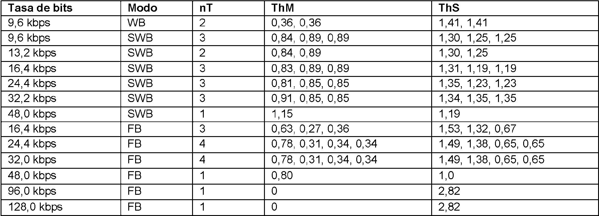
5.3.3.2.11.1.6 Nulo5.3.3.2.11.1.6 Null
5.3.3.2.11.1.7 Tablas del factor de escala IGF5.3.3.2.11.1.7 IGF scale factor tables
Las tablas del factor de escala IGF están disponibles para todos los modos donde se aplica IGF.IGF scale factor tables are available for all modes where IGF is applied.
Tabla 8: tabla de desplazamiento de la banda del factor de escalaTable 8: scale factor band offset table


La tabla 8 anterior se refiere a la ventana de longitud TCX 20 y un factor de transición 1,00.Table 8 above refers to the TCX 20 length window and a 1.00 transition factor.
Para todos las longitudes de ventana se aplican el siguiente remapeoThe following remapping applies to all window lengths
t{k):= tF ( t ( k \ f \ k = 0,1,2 , ... ,nB (72) donde ^ es la función del mapeo del factor de transición descrito en la subcláusula 5.3.3.2.11.1.1. t {k): = tF ( t ( k \ f \ k = 0,1,2 , ..., nB (72) where ^ is the mapping function of the transition factor described in subclause 5.3.3.2.11.1 .one.
5.3.3.2.11.1.8 La función de mapeo m 5.3.3.2.11.1.8 The mapping function m
Tabla 9: sub-banda de fuente mínima IGF, Table 9: IGF minimum source sub-band, minSbminSb

Para cada modo se define una función de mapeo para acceder a las líneas fuente desde una línea de destino dada en el intervalo IGF.For each mode a mapping function is defined to access the source lines from a given target line in the IGF interval.
Tabla 10: funciones de mapeo para cada modoTable 10: mapping functions for each mode


La función de mapeo se define con:The mapping function is defined with:

La función de mapeo m -â se define con:The mapping function m -â is defined with:
í minSb+ (x - i (O)) para /(o)< x < t { l ) í minSb + (x - i (O)) for / (o) <x < t {l)
m2a(x):~ (74) \m in S b (x - t (2 ) ) para /(2)<x<r(/>5) m2a ( x): ~ (74) \ m in S b ( x - t ( 2)) for / (2) <x <r (/> 5)
La función de mapeo m se define con:The mapping function m is defined with:
mínSb+(x~i(0)) para /(o)<x</(4) minSb + ( x ~ i (0)) for / (o) <x </ (4)
m2b{x):= (75) mmSb+ tF (32 ,f)+ (x -í(4)) para t(2) < x < t{nB) m2b {x): = (75) mmSb + tF ( 32, f) + ( x -í (4)) for t ( 2) < x <t {nB)
La función de mapeo se define con:The mapping function is defined with:
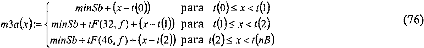
La función de mapeo se define conThe mapping function is defined with

La función de mapeo se define conThe mapping function is defined with

La función de mapeo se define con:The mapping function is defined with:

La función de mapeo se define con:The mapping function is defined with:

El valor f es el factor de transición apropiado, véase la tabla 11 y ^ se describe en la subcláusula 5.3.3.2.11.1.1. Por favor, obsérvese que todos los valores / ( o ) , / ( l tiiiB) se mapearán ya con la función tF, como se describe en la subcláusula 5.3.3.2.11.1.1. Los valores para se definen en la tabla 8.The value f is the appropriate transition factor, see Table 11 and ^ is described in subclause 5.3.3.2.11.1.1. Please note that all the values / (o), / (l tiiiB) will already be mapped with the tF function, as described in subclause 5.3.3.2.11.1.1. Values for are defined in table 8.
Las funciones de mapeo descritas en el presente documento se referirán en el texto como "función de mapeo m" asumiendo que se selecciona la función apropiada para el modo actual.The mapping functions described herein will be referred to in the text as "m mapping function" assuming the appropriate function is selected for the current mode.
5.3.3.2.11.2 Elementos de entrada de IGF (TX)5.3.3.2.11.2 IGF input elements (TX)
El módulo codificador IGF espera los siguientes vectores e indicadores como entrada:The IGF encoder module expects the following vectors and flags as input:
P :vector con parte real del espectro TCX actual M P : vector with real part of the current TCX spectrum M
I :vector con parte imaginario del espectro TCX actual 
P :vector con valores del espectro de potencia TCX p P : vector with values of the power spectrum TCX p
isTransient: indicador, que señaliza si la trama actual contiene un transitorio, véase la subcláusula 5.3.2.4.1.1 isTransient : indicator, which indicates if the current frame contains a transient, see subclause 5.3.2.4.1.1
LsTCXlO indicador, que señaliza una trama TCX 10LsTCXlO flag, which signals a TCX 10 frame
isTCX20 :indicador, que señaliza una trama TCX 20 isTCX 20: indicator, which signals a TCX 20 frame
isCelpToTCX : indicador, que señaliza la transición de CELP a TCX; generar el indicador por prueba si la última trama fue CELP isCelpToTCX : indicator, which signals the transition from CELP to TCX; generate flag by test if last frame was CELP
isIndepFlag indicador, que señaliza que la trama actual es independiente de la trama previa isIndepFlag flag, which indicates that the current frame is independent of the previous frame
Listado en la tabla 11, las siguientes combinaciones señalizadas a través de los indicadores isTCXIO, isTCXIO y isCelpToTCX se permiten con IGF:Listed in table 11, the following combinations signaled through the isTCXIO, isTCXIO and isCelpToTCX indicators are allowed with IGF:
Tabla 11: transiciones TCX, factor de transición / , longitud de ventana n Table 11: TCX transitions, transition factor / , window length n


5.3.3.2.11.3 Funciones IGF en el lado de transmisión (TX)5.3.3.2.11.3 IGF functions on the transmitting side (TX)
Toda la declaración de la función asume que los elementos de entrada se proporcionan en forma de trama a trama. Las únicas excepciones son dos tramas consecutivas TCX 10s, donde la segunda trama está codificada dependiendo de la primera trama.The entire declaration of the function assumes that the input elements are provided in frame-by-frame form. The only exceptions are two consecutive TCX 10s frames, where the second frame is encoded depending on the first frame.
5.3.3.2.11.4 Cálculo del factor de escala IGF5.3.3.2.11.4 Calculation of the IGF scale factor
Esta subcláusula describe cómo el vector del factor de escala IGF

5.3.3.2.11.4.1 Cálculo de valores complejos5.3.3.2.11.4.1 Calculation of complex values
En caso de que el espectro de potencia TCX está disponible, se calculan los valores del factor de escala IGF usando :In case the TCX power spectrum is available, the IGF scale factor values are calculated using:

y se permite que m '■ ^ N sea la función de mapeo que mapea el intervaloobjetivo de IGF en el intervalo fuente de IGF descrito en la subcláusula 5.3.3.2.11.1.8. calcular:and let m '■ ^ N be the mapping function that maps the IGF target interval to the IGF source interval described in subclause 5.3.3.2.11.1.8. calculate:

de bandas del factor de escala IGF, véase la tabla 8.of bands of the IGF scale factor, see Table 8.
Calcular g(k) con:Calculate g (k) with:

y limitar intervalo [0 ,9 l]e Z con and limit interval [0.9 l] e Z with
Los valores
5.3.3.2.11.4.2 Cálculo de valores reales5.3.3.2.11.4.2 Calculation of actual values
Si el espectro de potencia TCX no está disponible calcular:If TCX power spectrum is not available calculate:

donde ya se mapeará con la función ^ véase la subcláusula 5.3.3.2.11.1.1. y nB son el número de bandas, véase la tabla 8.where it will already be mapped with the ^ function see subclause 5.3.3.2.11.1.1. and nB are the number of bands, see table 8.
Calcular g(k) con:Calculate g (k) with:

y limitar intervalo[o,9l] c Z conand limit interval [o, 9l] c Z with
g(k)=Max(0,g(k)), g ( k) = Max ( 0, g ( k)),

g(£)E]mm(91,g{¿)).g (£) E] mm (91, g {?)).
Los valores ^ ^ )’ ■ 0,15■- - ^ 15 se transmitirán al lado del receptor (RX) después de la compresión sin pérdidas adicionales con un codificador aritmético descrito en la subcláusula 5.3.3.2.11.8.The values ^ ^) ' ■ 0.15 ■ - - ^ 15 shall be transmitted to the receiver side (RX) after compression without additional loss with an arithmetic encoder described in subclause 5.3.3.2.11.8.
5.3.3.2.11.5 Enmascaramiento tonal IGF5.3.3.2.11.5 IGF Tonal Masking
Con el fin de determinar qué componentes espectrales se deben transmitir con el codificador de núcleo, se calcula un enmascaramiento tonal. Por lo tanto, todo el contenido espectral significativo se identifica mientras que el contenido que es adecuado para la codificación paramétrica a través de IGF se cuantifica a cero.In order to determine which spectral components should be transmitted with the core encoder, a tonal masking is calculated. Therefore, all significant spectral content is identified while content that is suitable for parametric encoding via IGF is quantized to zero.
5.3.3.2.11.5.1 Cálculo del enmascaramiento tonal IGF5.3.3.2.11.5.1 Calculation of IGF tonal masking
En el caso de que el espectro de potencia TCX no está disponible, se suprime el contenido espectral total anterior :In case the TCX power spectrum is not available, the previous total spectral content is suppressed:
R ( t b ) 0, í(o) <tb< í{nB) 
donde R es el espectro TCX de valor real después de aplicar TNS y n es la longitud de ventana TCX actual.where R is the actual value TCX spectrum after applying TNS and n is the current TCX window length.
En caso de que el espectro de potencia TCX P está disponible, calcular:In case the TCX P power spectrum is available, calculate:

donde es la primera línea espectral en el intervalo IGF.where is the first spectral line in the IGF interval.
Dado , aplicar el siguiente algoritmo: Given, apply the following algorithm:
Inicializar last y next . Initialize last and next.

5.3.3.2.11.6 Cálculo de planitud espectral IGF5.3.3.2.11.6 IGF spectral flatness calculation
Tabla 12: número de mosaicos n T y ancho del mosaico ![]()
![]()

Para el cálculo de la planitud espectral de IGF se necesitan dos matrices estáticas PrevE^E y PrevH R , y ambos de tamaño nE son necesarios para mantener los estados de filtro sobre tramas. Adicionalmente, se necesita un indicador estático wosTransient para guardar la información del indicador de entrada isTransient de la trama anterior.For the calculation of the spectral flatness of IGF, two static matrices PrevE ^ E and PrevH R are needed, and both of size nE are necessary to maintain the filter states on frames. Additionally, a static wosTransient flag is needed to store the isTransient input flag information from the previous frame.
5.3.3.2.11.6.1 Restablecimiento de los estados de filtro5.3.3.2.11.6.1 Resetting the filter states
Los vectores PrevE^R yprevIIR son ambos matrices estáticas de tamaño en el módulo IGF y ambas matrices se inicializan con ceros: The vectors PrevE ^ R and prevIIR are both static size matrices in the IGF module and both matrices are initialized with zeros:

Esta inicialización se realizaráThis initialization will be done
- con inicio de códec- with codec start
- con cualquier conmutador de tasa de bits- with any bitrate switch
- con cualquier conmutador de tipo códec- with any codec type switch
- con una transición de CELP a TCX, por ejemplo, isCelpToTCX - true - with a transition from CELP to TCX, for example isCelpToTCX - true
- si la trama actual tiene propiedades transitorias, por ejemplo,. isTransient = true - if the current frame has transient properties, eg. isTransient = true
5.3.3.2.11.6.2 Restablecimiento de los niveles de blanqueamiento actuales5.3.3.2.11.6.2 Restoring current whitening levels
El vector currWLevel se inicializará con cero para todos los mosaicos,The currWLevel vector will be initialized with zero for all tiles,

- con inicio de códec- with codec start
- con cualquier conmutador de tasa de bits- with any bitrate switch
- con cualquier conmutador de tipo códec- with any codec type switch
- con una transición de CELP a TCX, por ejemplo, tsCelpToTCX - true - with a transition from CELP to TCX, for example tsCelpToTCX - true
5.3.3.2.11.6.3 Cálculo de los índices de plenitud espectral5.3.3.2.11.6.3 Calculation of spectral fullness indices
Las siguientes etapas 1) a 4) se ejecutarán de modo consecutivo:The following stages 1) to 4) will be executed consecutively:
1) Actualizar búfer de nivel previo e inicializar niveles actuales:1) Update previous level buffer and initialize current levels:

En caso de que ![]()
![]()

además, si la espectro de potencia está disponible, calcularAlso, if the power spectrum is available, calculate

conwith

donde SFM es una función de medición de la planitud espectral, descrita en la subcláusula 5.3.3.2.11.1.3 y CREST es un factor de cresta descrito en la subcláusula 5.3.3.2.11.1.4.where SFM is a spectral flatness measurement function, described in subclause 5.3.3.2.11.1.3 and CREST is a crest factor described in subclause 5.3.3.2.11.1.4.
Calcular: Calculate:
s(k) := miní 2.1 ,tmp{k)+ prevFIR.(k )+ 2 prevIIR.(k) (97) s ( k) : = mini 2.1, tmp {k) + prevFIR. ( k ) + 2 prevIIR. ( k) (97)
Después del cálculo del vector
prevFlR{k) = tmp{k), k = 0 , 1 , 1 prevFlR {k) = tmp {k), k = 0, 1, 1
prevIIR.(k) = s {k \ k = 0,1,... ,n T - l (98) PREVIOUS. ( k ) = s {k \ k = 0,1, ..., n T - l (98)
prevIsTransient = isTransientprevIsTransient = isTransient
2) Una función de mapeo![]()
![]()
![]()
![]()
currWLevel (k) = hT {s(k \k \ k = 051,...»mT -1 (99) currWLevel ( k) = hT {s ( k \ k \ k = 051, ... » m T -1 (99)
3) Con los modos seleccionados, véase la tabla 13, aplicar el siguiente mapeo final:3) With the modes selected, see table 13, apply the following final mapping:
currW LeveinT — l) := currWLeve^nT - 2) ( 100) currW LeveinT - l): = currWLeve ^ nT - 2) ( 100 )
Tabla 13: modos para la etapa 4) mapeoTable 13: modes for stage 4) mapping

Después de ejecutar la etapa 4) el vector del índice de nivel de blanqueamiento currWLevel está listo para la transmisión.After executing step 4) the currWLevel whitening level index vector is ready for transmission.
5.3.3.2.11.6.4 Codificación de los niveles de blanqueamiento de IGF5.3.3.2.11.6.4 Coding of IGF bleaching levels
Los niveles de blanqueamiento de IGF, definidos en el vector currWLevel, se transmiten usando 1 o 2 bits por mosaico. El número exacto de bits totales requeridos depende de los valores reales contenidos en currWLevel y el valor del indicador is^ eP . El proceso detallado se describe en el pseudo-código a continuación:IGF whitening levels, defined in the currWLevel vector, are transmitted using 1 or 2 bits per mosaic. The exact number of total bits required depends on the actual values contained in currWLevel and the value of the is ^ eP flag. The detailed process is described in the pseudo-code below:
isSame = 1; isSame = 1;
nTiles = nT ; . nTiles = nT ; .
k = 0;k = 0;
si îslndep) {yes îslndep) {
isSame = o isSame = o
} además {} what's more {
para (k = 0; k < nTiles ; k++) {for (k = 0; k <nTiles; k ++) {
currWLevel(k) (_ prevWLevel[k) currWLevel (k) (_ prevWLevel [k)
si ( ) { Yes ( ) {
isSame = 0-romper; isSame = 0-break;
}}
}}
}}

donde el vector prevWLevel contiene los niveles de blanqueamiento de la trama previa y la función encode_whitening_level se ocupa del mapeo real del nivel de blanqueamiento curr WLevelty) a un código binario. La función se implementa según el pseudo-código siguiente:where the vector prevWLevel contains the whitening levels of the previous frame and the function encode_whitening_level deals with the actual mapping of the whitening level curr WLevelty) to a binary code. The function is implemented according to the following pseudo-code:
si (cwrr^Zeve/^)==1) {if (cwrr ^ Zeve / ^) == 1) {
write_bit(0);write_bit (0);
} además {} what's more {
write_bit(1);write_bit (1);
currWLevel(i)== 0) {si ( currWLevel ( i) == 0) { if (
write_bit(0);write_bit (0);
} además {} what's more {
write bit(1);write bit (1);
}}
}}
5.3.3.2.11.7 Indicador de la planitud temporal IGF5.3.3.2.11.7 IGF temporal flatness indicator
La envolvente temporal de la señal reconstruida por el IGF se aplana en el lado del receptor (RX) según la información transmitida sobre la planitud de la envolvente temporal, que es un indicador de planitud IGF.The time envelope of the signal reconstructed by the IGF is flattened on the receiver side (RX) according to the information transmitted about the flatness of the time envelope, which is an indicator of IGF flatness.
La planitud temporal se mide como la ganancia de predicción lineal en el dominio de frecuencia. En primer lugar, se realiza la predicción lineal de la parte real del espectro TCX actual y luego se calcula la ganancia de predicción : Temporal flatness is measured as the linear prediction gain in the frequency domain. First, the linear prediction of the real part of the current TCX spectrum is performed, and then the prediction gain is calculated:

donde ^ = coeficiente Z—th PARCOR obtenido por la predicción lineal.where ^ = Z — th PARCOR coefficient obtained by linear prediction.
f j . pf j. p
A partir de la ganancia de predicción y la ganancia de predicción![]()
![]()

5.3.3.2.11.8 Codificación sin ruido IGF5.3.3.2.11.8 IGF Noiseless Coding
El vector de factor de escala de IGF & se codifica sin ruido con un codificador aritmético con el fin de escribir una representación eficiente del vector al flujo de bits. The IGF & scale factor vector is encoded noiselessly with an arithmetic encoder in order to write an efficient representation of the vector to the bit stream.
El módulo utiliza las funciones comunes de codificador aritmético bruto de la infraestructura, que son proporcionados or el i cod ji ífi -cad ,or d ,e nú .cl ieo. i Las f .unciones usad ,as son, ari encode 14bits sieinbit) ue cod .i.f..ica el . val .orb ..it., The module uses the common raw arithmetic encoder functions of the infrastructure, which are provided by the i code j i i fi -cad, or d, e number. i The f. functions used, as they are, ari encode 14 bits sieinbit) which encodes the. val . orb ..it.,

5.3.3.2.11.8.1 Indicador de independencia IGF5.3.3.2.11.8.1 IGF independence indicator
El estado interno del codificador aritmético se restablece en caso de que el indicador 
5.3.3.2.11.8.2 Indicadores todo cero IGF5.3.3.2.11.8.2 All zero IGF indicators
El indicador IGF todo cero señala que todos los factores de escala IGF son ceroThe all-zero IGF indicator indicates that all IGF scale factors are zero

El indicador a^ ero se escribe en el primer flujo de bits. En el caso de que el indicador es true , el estado del codificador se restablece y no se escriben más datos en el flujo de bits, de lo contrario el vector del factor de escala codificado aritmético & sigue en el flujo de bits.The a ^ ero flag is written to the first bit stream. In the case where the flag is true , the encoder state is reset and no more data is written to the bit stream, otherwise the arithmetic encoded scale factor vector & remains in the bit stream.
5.3.3.2.11.8.3 Funciones auxiliares que codifican IGF aritmético5.3.3.2.11.8.3 Auxiliary functions encoding arithmetic IGF
5.3.3.2.11.8.3.1 La función de restablecimiento5.3.3.2.11.8.3.1 The reset function
Los estados codificadores aritméticos consisten en f e ^ ’1}, y el vector Prev , que representa el valor del vector & conservado de la trama anterior. Al codificar el vector & , el valor 0 para medios t significa que no hay trama previa disponible, por lo tanto Prev no está definido y no se usa. Por lo tanto, el valor 1 para mediost que existe una trama previa disponible Prev tiene datos válidos y se utiliza, este el caso solo en los modos en los que se utilizan ventanas TCX10 (véase la tabla 11) para la segunda trama de dos tramas TCX 10 consecutivas. Para restablecer el estado del codificador aritmético, es suficiente para establecer 1 . The arithmetic encoding states consist of f e ^ '1}, and the vector P rev, which represents the value of the conserved vector & from the previous frame. When encoding the vector & , the value 0 for means t means that there is no previous frame available, therefore Prev is not defined and is not used. Therefore, the value 1 for meanst that there is a previous frame available Prev has valid data and is used, this is the case only in the modes in which TCX10 windows are used (see table 11) for the second frame of two frames TCX 10 in a row. To reset the arithmetic encoder state, it is enough to set 1.
Si se ha establecido una trama ^ ndepFlag , el estado del codificador se restablece antes de codificar el vector del If a ^ ndepFlag frame has been set, the encoder state is reset before encoding the vector of the
factor de escala & . Cabe señalar que la combinación 1 = 0 y ^ndepFlag - false es válida, y puede suceder para scale factor & . It should be noted that the combination 1 = 0 and ^ ndepFlag - false is valid, and it can happen for
la segunda trama de dos tramas TCX 10 consecutivas, cuando la primera trama tenía ollZero = l . En este caso particular, la trama no usa información de contexto de la trama previa (el vector ), porque , y está codificado actualmente como una trama independiente.the second frame of two consecutive TCX 10 frames, when the first frame had ollZero = l. In this particular case, the frame does not use context information from the previous frame (the vector), because, and is currently encoded as a separate frame.
5.3.3.2.11.8.3.2 La función arith encode bits5.3.3.2.11.8.3.2 The arith encode bits function
La función ardh_encode_bits codifica un número entero sin signo x ,de longitud nBits bits, mediante la escritura de un bit a la vez.The ardh_encode_bits function encodes an unsigned integer x , of length nBits bits, by writing one bit at a time.
arith_encode_bits(x, nBits)arith_encode_bits (x, nBits)
{{
para (i = nBits - 1; i >= 0; — i) {for (i = nBits - 1; i> = 0; - i) {
bit = (x >> i) & 1;bit = (x >> i) &1;
ari_encode_14bits_sign(bit);ari_encode_14bits_sign (bit);
}}
}}
5.3.3.2.11.8.3.2 Las funciones guardar y restaurar del estado del codificador5.3.3.2.11.8.3.2 The Encoder Status Save and Restore Functions
El guardado del estado del codificador se obtiene usando la función![]()
![]()
![]()
![]()
y el . vec .tor p ^ revSave en ' t y el , vec *tor ^ , respect ..ivament .e.and the . vec . tor p ^ revSave in ' t and el , vec * tor ^ , respect .. ivament . and.
5.3.3.2.11.8.4 Codificación aritmética IGF5.3.3.2.11.8.4 IGF arithmetic encoding
Se debe observar que el codificador aritmético debe ser capaz de contar bits solamente, por ejemplo, realizar la codificación aritmética sin escribir bits en el flujo de bits. Si se pide el codificador aritmético con una solicitud de It should be noted that the arithmetic encoder must be able to count bits only, eg perform arithmetic encoding without writing bits to the bit stream. If the arithmetic encoder is requested with a request for
recuento, mediante el uso del parámetro ajustado ajustado a el estado interno del codificador aritmético se deberá guardar antes de la llamada a la función de nivel superior iisIGFSCFEncoderEncode y se restaurar y después de la llamada por la persona que llama. En este caso particular, los bits generados internamente por el codificador aritmético no se escriben en el flujo de bits.La función arith_encode_residual codifica el residuo de predicción de valor entero x , usando la tabla de frecuencia count, by using the parameter set to the internal state of the arithmetic encoder, it should be saved before the call to the top-level function iisIGFSCFEncoderEncode and restored and after the call by the caller. In this particular case, the bits generated internally by the arithmetic coder is not written to the stream encoding bits.La arith_encode_residual the prediction residual function value integer x, using the frequency table
acumulativa , y el desplazamiento de la tabla
codificados directamente usando la tabla de frecuencia acumulativa
Para el alfabeto anterior de símbolos SYMBOLS_IN_TABLE, los valores 0 y SYMBOLS _ IN _TABLE 1 están reservados como códigos de escape para indicar que un valor es demasiado pequeño o demasiado grande para caber en el intervalo predeterminado. En estos casos, el valor indica la posición del valor en una de las colas For the previous alphabet of SYMBOLS_IN_TABLE symbols, the values 0 and SYMBOLS _ IN _TABLE 1 are reserved as escape codes to indicate that a value is too small or too large to fit in the predetermined range. In these cases, the value indicates the position of the value in one of the queues
de la distribución. El valor se codifica usando 4 bits si está en el intervalo{0,---,14}, o usando 4 bits con of the distribution. The value is encoded using 4 bits if it is in the range {0, ---, 14}, or using 4 bits with
valor 15 seguido de 6 bits extra si está en el intervalo {15 .,15 62} o usando 4 bits con valor 15 seguido de 6 bits extra con valor 63 seguido por 7 bits extra si es mayor o igual que 15 63. El último de los tres casos es principalmente útil para evitar la rara situación en la que una señal artificial construida a propósito puede producir una condición de valor residual inesperadamente grande en el codificador. value 15 followed by 6 extra bits if it is in the range {15. , 15 62} or using 4 bits with value 15 followed by 6 extra bits with value 63 followed by 7 extra bits if it is greater than or equal to 15 63. The last Of the three cases, it is mainly useful to avoid the rare situation where a purposefully constructed artificial signal can produce an unexpectedly large residual value condition in the encoder.
arith_encode_residual(x, cumulativeFrequencyTable, tableOffset)arith_encode_residual (x, cumulativeFrequencyTable, tableOffset)
{{
x = tableOffset;x = tableOffset;
si ((x >= MIN_ENC_SEPARATE) && (x <= MAX_ENC_SEPARATE)) {if ((x> = MIN_ENC_SEPARATE) && (x <= MAX_ENC_SEPARATE)) {
ari_encode_14bits_ext((x - MIN_ENC_SEPARATE) 1, cumulativeFrequencyTable);ari_encode_14bits_ext ((x - MIN_ENC_SEPARATE) 1, cumulativeFrequencyTable);
volver;return;
} además si (x < MIN_ENC_SEPARATE) {} also if (x <MIN_ENC_SEPARATE) {
extra = (MIN_ENC_SEPARATE - 1) - x;extra = (MIN_ENC_SEPARATE - 1) - x;
ari_encode_14bits_ext(0, cumulativeFrequencyTable);ari_encode_14bits_ext (0, cumulativeFrequencyTable);
} además { /* x > MAX_ENC_SEPARATE */} also {/ * x> MAX_ENC_SEPARATE * /
extra = x - (MAX_ENC_SEPARATE 1);extra = x - (MAX_ENC_SEPARATE 1);
ari_encode_14bits_ext(SYMBOLS_IN_TABLA - 1, cumulativeFrequencyTable);ari_encode_14bits_ext (SYMBOLS_IN_TABLA - 1, cumulativeFrequencyTable);
}}
si (extra < 15) {yes (extra <15) {
arith_encode_bits(extra, 4);arith_encode_bits (extra, 4);
} además { /* extra >= 15 */} also {/ * extra> = 15 * /
arith_encode_bits(15, 4);arith_encode_bits (15, 4);
extra -= 15;extra - = 15;
si (extra < 63) {yes (extra <63) {
arith_encode_bits(extra, 6);arith_encode_bits (extra, 6);
} además { /* extra >= 63 */} also {/ * extra> = 63 * /
arith_encode_bits(63, 6);arith_encode_bits (63, 6);
extra -= 63;extra - = 63;
arith_encode_bits(extra, 7);arith_encode_bits (extra, 7);
}}
}}
}}
La función enco(^e_ sf e_ vector codifica el vector del factor de escala & , que consiste en valores enteros . El valor 1 y el vector Prev , que constituye el estado del codificador, se usan como parámetros adicionales para la función. Cabe señalar que la función del nivel superior iisIGFSCFEncoderEncode debe llamar la función de The enco ( ^ e_ sf e_ vector function encodes the scale factor vector & , which consists of integer values . The value 1 and the vector P rev, which constitutes the state of the encoder, are used as additional parameters for the function. Note that the top-level function iisIGFSCFEncoderEncode should call the function
inicialización del codificador aritmético común a r i_ start_ encoding_l4bits antes de llamar la función initialization of the common arithmetic encoder ar i_ start_ encoding_l4bits before calling the function
encode_sfe_vector, y también llamar la función de finalización del codificador aritmético encode_sfe_vector, and also call the completion function of the arithmetic encoder
después.then.
.La f .unci .ó.n quant ctx se usa para cuant ..i.f.icar un val .or d ,e cont .ext .o r tr mediante su limitación a { - 3,...,3} y se define como: . The f . unci . or . n quant ctx is used for quant .. i . f . icar a val . or d , e cont . ext . or r tr by limiting it to {- 3, ..., 3} and is defined as:
quant_ctx(ctx)quant_ctx (ctx)
{{
si (abs(ctx) <= 3) {if (abs (ctx) <= 3) {
volver ctx;return ctx;
} además si (ctx > 3) {} also if (ctx> 3) {
volver 3;return 3;
} además { /* ctx < -3 */} also {/ * ctx <-3 * /
volver -3;return -3;
}}
}}
Las definiciones de los nombres simbólicos indicados en los comentarios del pseudo-código, utilizados para calcular los valores de contexto, se enumeran en la siguiente tabla 14:The definitions of the symbolic names indicated in the pseudo-code comments, used to calculate the context values, are listed in the following table 14:
Tabla 14: definición de nombres simbólicosTable 14: definition of symbolic names


encode_sfe_vector(t, prev, g, nB)encode_sfe_vector (t, prev, g, nB)
para (f = 0; f < nB; f++) {for (f = 0; f <nB; f ++) {
si (t == 0) {if (t == 0) {
si (f == 0) {if (f == 0) {
ari_encode_14bits_ext(g[f] >> 2, cf_se00);ari_encode_14bits_ext (g [f] >> 2, cf_se00);
arith_encode_bits(g[f] & 3, 2); /* LSBs como 2bit sin procesar*/arith_encode_bits (g [f] & 3, 2); / * LSBs as raw 2bit * /
}}
además si (f == 1) {also if (f == 1) {
pred = g[f - 1]; /* pred = b */pred = g [f-1]; / * pred = b * /
arith_encode_residual(g[f] - pred, cf_se01, cf_off_se01);arith_encode_residual (g [f] - pred, cf_se01, cf_off_se01);
} además { /* f >= 2 */} also {/ * f> = 2 * /
pred = g[f - 1]; /* pred = b */pred = g [f-1]; / * pred = b * /
ctx = quant_ctx(g[f - 1] - g[f - 2]); /* Q(b - e) */ctx = quant_ctx (g [f-1] - g [f-2]); / * Q (b - e) * /
arith_encode_residual(g[f] - pred, cf_se02[CTX_DESPLAZAMIENTO ctx)],arith_encode_residual (g [f] - pred, cf_se02 [CTX_DESPLAZAMIENTO ctx)],
cf_off_se02[IGF_CTX_DESPLAZAMIENTO ctx]);cf_off_se02 [IGF_CTX_SLIFT ctx]);
}}
}}
además { /* t == 1 */also {/ * t == 1 * /
si (f == 0) {if (f == 0) {
pred = prev[f]; /* pred = a */pred = prev [f]; / * pred = a * /
arith_encode_residual(x[f] - pred, cf_se10, cf_off_se10);arith_encode_residual (x [f] - pred, cf_se10, cf_off_se10);
} además { /* (t == 1) && (f >= 1) */} also {/ * (t == 1) && (f> = 1) * /
pred = prev[f] g[f - 1] - prev[f - 1]; /* pred = a b - c */pred = prev [f] g [f-1] - prev [f-1]; / * pred = a b - c * /
ctx_f = quant_ctx(prev[f] - prev[f - 1]); /* Q(a - c) */ctx_f = quant_ctx (prev [f] - prev [f - 1]); / * Q (a - c) * /
ctx_t = quant_ctx(g[f - 1] - prev[f - 1]); /* Q(b - c) */ctx_t = quant_ctx (g [f-1] - prev [f-1]); / * Q (b - c) * /
arith_encode_residual(g[f] - pred,arith_encode_residual (g [f] - pred,
cf_se11[CTX_OFFSET ctx_t][CTX_OFFSET ctx_f)],cf_se11 [CTX_OFFSET ctx_t] [CTX_OFFSET ctx_f)],
cf_off_se11[CTX_OFFSET ctx_t][CTX_OFFSET ctx_f]);cf_off_se11 [CTX_OFFSET ctx_t] [CTX_OFFSET ctx_f]);
}}
}}
}}
}}
Existen cinco casos en la función anterior, que dependen del valor de ^ y también de la posición f de un valor en el vector:There are five cases in the above function, which depend on the value of ^ and also on the position f of a value in the vector:
- cuando y f ^ , el primer factor de escala de una trama independiente se codifica, mediante su división en los bits más significativos que están codificados usando la tabla de frecuencia acumulativa cJf - jS^ OO , y por lo menos dos bits significativos codificados directamente.- when y f ^, the first scale factor of an independent frame is encoded, by dividing it into the most significant bits that are encoded using the cumulative frequency table c J f - jS ^ OO , and at least two significant bits encoded directly.
- cuando 
residuo de predicción) usando la tabla de frecuencia acumulativa cf iS^ Ol .prediction residual) using the cumulative frequency table cf iS ^ Ol .
- cuando y , se codifican el tercer y los siguientes factores de escala de una trama independiente (como residuos de predicción) usando la tabla de frecuencia acumulativa - when and, the third and subsequent scale factors of an independent frame (as prediction residuals) are encoded using the cumulative frequency table
, determinado por el valor de contexto cuantificado ., determined by the quantized context value.
- cuando y 
de predicción) usando la tabla de frecuencia acumulativa c Jf - sc \0.prediction) using the cumulative frequency table c J f - sc \ 0 .
- cuando y , se codifican el segundo y los siguientes factores de escala de una trama dependiente (como residuos de predicción) usando la tabla de frecuencia acumulativa cy f - se\\\ LCTX - OFFSET ctx tiC TX OFFSET ctx - j f \ t- d ,et .ermi .nad ,o por los valores de contexto cuant ..i.f.icad ,os ctx - t y ctx f .- when and, the second and subsequent scale factors of a dependent frame (as prediction residuals) are encoded using the cumulative frequency table c and f - se \\\ L CTX - OFFSET ctx tiC TX OFFSET ctx - j f \ t- d, et .ermi .nad, or by the context values quant .. i . f . icad , os ctx - t and ctx f .
Cabe señalar que las tablas de frecuencias acumulativas predefinidas c f _se 01 c f _ se 02 y los desplazamientos de la tabla cf _ 0f f _ se 01 cf _ ° f f _ se 02 dependen del punto operativo actual e implícitamente de la tasa de bits, y se seleccionan del conjunto de opciones disponibles durante la inicialización del codificador para cada punto operativo determinado. La tabla de frecuencia acumulativa c f jS^OO es común para todos los puntos operativos, y tablas de frecuencia acumulativa y y los correspondientes desplazamientos de la tabla y también son comunes pero se usan solo para los puntos operativos correspondiente a las tasas de bits más grandes o iguales que 48 kbps, en el caso de las tramas TCX 10 dependientes (cuando ).It should be noted that the predefined cumulative frequency tables cf _se 01 cf _ se 02 and the offsets of the cf table _ 0f f _ se 01 cf _ ° ff _ se 02 depend on the current operating point and implicitly on the bit rate, and they are selected from the set of options available during encoder initialization for each given operating point. The cumulative frequency table cf j S ^ OO is common for all operating points, and the cumulative frequency tables y and the corresponding table offsets and are also common but used only for the operating points corresponding to the largest bit rates or equal to 48 kbps, in the case of dependent TCX 10 frames (when).
5.3.3.2.11.9 Escritor de flujo de bits IGF5.3.3.2.11.9 IGF Bitstream Writer
Los factores de escala IGF codificados aritméticamente, los niveles de blanqueamiento IGF y el indicador de planitud temporal IGF se transmiten consecutivamente al lado del decodificador a través del flujo de bits. La codificación de los factores de escala IGF se describe en la subcláusula 5.3.3.2.11.8.4. Los niveles de blanqueamiento de IGF se codifican como se presenta en la subcláusula 5.3.3.2.11.6.4. Finalmente, el indicador de planitud temporal IGF, representado como un bit, se escribe en el flujo de bits.The arithmetically encoded IGF scale factors, the IGF whitening levels and the IGF time flatness indicator are transmitted consecutively to the decoder side through the bit stream. The coding of the IGF scale factors is described in subclause 5.3.3.2.11.8.4. IGF bleaching levels are coded as presented in subclause 5.3.3.2.11.6.4. Finally, the temporal flatness indicator IGF, represented as a bit, is written to the bit stream.
En el caso de una trama TCX20, es decir, , y ninguna solicitud de recuento se señaliza al escritor del flujo de bits, la salida del escritor del flujo de bits alimenta directamente al flujo de bits. En el caso de una trama TCX10 (isTCXXO = true ), en la que dos subtramas están codificadas dependientemente dentro de una trama de 20 ms, la salida del escritor de flujo de bits para cada subtrama se escribe en un búfer temporal, que produce un flujo de bits que contiene la salida del escritor del flujo de bits para las subtramas individuales. El contenido de este búfer temporal se escribe finalmente en el flujo de bits. In the case of a TCX20 frame, that is, and no count request is signaled to the bitstream writer, the bitstream writer output feeds directly into the bitstream. In the case of a TCX10 frame ( isTCXXO = true ), in which two subframes are dependently encoded within a 20 ms frame, the bitstream writer output for each subframe is written to a temporary buffer, which produces a bitstream containing the bitstream writer output for individual subframes. The content of this temporary buffer is eventually written to the bit stream.
Claims (26)
Applications Claiming Priority (2)
| Application Number | Priority Date | Filing Date | Title |
|---|---|---|---|
| EP16164951 | 2016-04-12 | ||
| PCT/EP2017/058238 WO2017178329A1 (en) | 2016-04-12 | 2017-04-06 | Audio encoder for encoding an audio signal, method for encoding an audio signal and computer program under consideration of a detected peak spectral region in an upper frequency band |
Publications (1)
| Publication Number | Publication Date |
|---|---|
| ES2808997T3 true ES2808997T3 (en) | 2021-03-02 |
Family
ID=55745677
Family Applications (2)
| Application Number | Title | Priority Date | Filing Date |
|---|---|---|---|
| ES20168799T Active ES2933287T3 (en) | 2016-04-12 | 2017-04-06 | Audio encoder for encoding an audio signal, method for encoding an audio signal and computer program in consideration of a spectral region of the detected peak in a higher frequency band |
| ES17715745T Active ES2808997T3 (en) | 2016-04-12 | 2017-04-06 | Audio encoder for encoding an audio signal, method for encoding an audio signal and computer program in consideration of a spectral region of the peak detected in a higher frequency band |
Family Applications Before (1)
| Application Number | Title | Priority Date | Filing Date |
|---|---|---|---|
| ES20168799T Active ES2933287T3 (en) | 2016-04-12 | 2017-04-06 | Audio encoder for encoding an audio signal, method for encoding an audio signal and computer program in consideration of a spectral region of the detected peak in a higher frequency band |
Country Status (20)
| Country | Link |
|---|---|
| US (3) | US10825461B2 (en) |
| EP (3) | EP3443557B1 (en) |
| JP (3) | JP6734394B2 (en) |
| KR (1) | KR102299193B1 (en) |
| CN (3) | CN109313908B (en) |
| AR (1) | AR108124A1 (en) |
| AU (1) | AU2017249291B2 (en) |
| BR (1) | BR112018070839A2 (en) |
| CA (1) | CA3019506C (en) |
| ES (2) | ES2933287T3 (en) |
| FI (1) | FI3696813T3 (en) |
| MX (1) | MX2018012490A (en) |
| MY (1) | MY190424A (en) |
| PL (2) | PL3443557T3 (en) |
| PT (2) | PT3443557T (en) |
| RU (1) | RU2719008C1 (en) |
| SG (1) | SG11201808684TA (en) |
| TW (1) | TWI642053B (en) |
| WO (1) | WO2017178329A1 (en) |
| ZA (1) | ZA201806672B (en) |
Families Citing this family (9)
| Publication number | Priority date | Publication date | Assignee | Title |
|---|---|---|---|---|
| EP3671741A1 (en) * | 2018-12-21 | 2020-06-24 | FRAUNHOFER-GESELLSCHAFT zur Förderung der angewandten Forschung e.V. | Audio processor and method for generating a frequency-enhanced audio signal using pulse processing |
| WO2020171034A1 (en) * | 2019-02-20 | 2020-08-27 | ヤマハ株式会社 | Sound signal generation method, generative model training method, sound signal generation system, and program |
| CN110047519B (en) * | 2019-04-16 | 2021-08-24 | 广州大学 | Voice endpoint detection method, device and equipment |
| WO2020253941A1 (en) * | 2019-06-17 | 2020-12-24 | Fraunhofer-Gesellschaft zur Förderung der angewandten Forschung e.V. | Audio encoder with a signal-dependent number and precision control, audio decoder, and related methods and computer programs |
| CN113192523A (en) * | 2020-01-13 | 2021-07-30 | 华为技术有限公司 | Audio coding and decoding method and audio coding and decoding equipment |
| CN113539281A (en) * | 2020-04-21 | 2021-10-22 | 华为技术有限公司 | Audio signal encoding method and apparatus |
| CN111613241B (en) * | 2020-05-22 | 2023-03-24 | 厦门理工学院 | High-precision high-stability stringed instrument fundamental wave frequency detection method |
| CN112397043B (en) * | 2020-11-03 | 2021-11-16 | 北京中科深智科技有限公司 | Method and system for converting voice into song |
| CN112951251B (en) * | 2021-05-13 | 2021-08-06 | 北京百瑞互联技术有限公司 | LC3 audio mixing method, device and storage medium |
Family Cites Families (47)
| Publication number | Priority date | Publication date | Assignee | Title |
|---|---|---|---|---|
| US4672670A (en) * | 1983-07-26 | 1987-06-09 | Advanced Micro Devices, Inc. | Apparatus and methods for coding, decoding, analyzing and synthesizing a signal |
| JP3125543B2 (en) * | 1993-11-29 | 2001-01-22 | ソニー株式会社 | Signal encoding method and apparatus, signal decoding method and apparatus, and recording medium |
| DE19804581C2 (en) * | 1998-02-05 | 2000-08-17 | Siemens Ag | Method and radio communication system for the transmission of voice information |
| US6975254B1 (en) * | 1998-12-28 | 2005-12-13 | Fraunhofer-Gesellschaft Zur Foerderung Der Angewandten Forschung E.V. | Methods and devices for coding or decoding an audio signal or bit stream |
| SE9903553D0 (en) | 1999-01-27 | 1999-10-01 | Lars Liljeryd | Enhancing conceptual performance of SBR and related coding methods by adaptive noise addition (ANA) and noise substitution limiting (NSL) |
| GB9917985D0 (en) * | 1999-07-30 | 1999-09-29 | Scient Generics Ltd | Acoustic communication system |
| JP2001143384A (en) * | 1999-11-17 | 2001-05-25 | Sharp Corp | Device and method for degital signal processing |
| US7330814B2 (en) * | 2000-05-22 | 2008-02-12 | Texas Instruments Incorporated | Wideband speech coding with modulated noise highband excitation system and method |
| US6587816B1 (en) * | 2000-07-14 | 2003-07-01 | International Business Machines Corporation | Fast frequency-domain pitch estimation |
| AU2211102A (en) * | 2000-11-30 | 2002-06-11 | Scient Generics Ltd | Acoustic communication system |
| US20020128839A1 (en) * | 2001-01-12 | 2002-09-12 | Ulf Lindgren | Speech bandwidth extension |
| CA2388352A1 (en) * | 2002-05-31 | 2003-11-30 | Voiceage Corporation | A method and device for frequency-selective pitch enhancement of synthesized speed |
| CN1328707C (en) * | 2002-07-19 | 2007-07-25 | 日本电气株式会社 | Audio decoding device, decoding method, and program |
| US7650277B2 (en) * | 2003-01-23 | 2010-01-19 | Ittiam Systems (P) Ltd. | System, method, and apparatus for fast quantization in perceptual audio coders |
| US7272551B2 (en) * | 2003-02-24 | 2007-09-18 | International Business Machines Corporation | Computational effectiveness enhancement of frequency domain pitch estimators |
| US20050004793A1 (en) * | 2003-07-03 | 2005-01-06 | Pasi Ojala | Signal adaptation for higher band coding in a codec utilizing band split coding |
| EP2221807B1 (en) | 2003-10-23 | 2013-03-20 | Panasonic Corporation | Spectrum coding apparatus, spectrum decoding apparatus, acoustic signal transmission apparatus, acoustic signal reception apparatus and methods thereof |
| KR20060132697A (en) * | 2004-02-16 | 2006-12-21 | 코닌클리케 필립스 일렉트로닉스 엔.브이. | A transcoder and method of transcoding therefore |
| KR100721537B1 (en) * | 2004-12-08 | 2007-05-23 | 한국전자통신연구원 | Apparatus and Method for Highband Coding of Splitband Wideband Speech Coder |
| UA91853C2 (en) * | 2005-04-01 | 2010-09-10 | Квелкомм Инкорпорейтед | Method and device for vector quantization of spectral representation of envelope |
| BRPI0608269B8 (en) * | 2005-04-01 | 2019-09-03 | Qualcomm Inc | Method and apparatus for vector quantization of a spectral envelope representation |
| WO2007026827A1 (en) * | 2005-09-02 | 2007-03-08 | Japan Advanced Institute Of Science And Technology | Post filter for microphone array |
| JPWO2007043643A1 (en) * | 2005-10-14 | 2009-04-16 | パナソニック株式会社 | Speech coding apparatus, speech decoding apparatus, speech coding method, and speech decoding method |
| US8032371B2 (en) * | 2006-07-28 | 2011-10-04 | Apple Inc. | Determining scale factor values in encoding audio data with AAC |
| US8135047B2 (en) * | 2006-07-31 | 2012-03-13 | Qualcomm Incorporated | Systems and methods for including an identifier with a packet associated with a speech signal |
| US9496850B2 (en) * | 2006-08-04 | 2016-11-15 | Creative Technology Ltd | Alias-free subband processing |
| KR101046982B1 (en) * | 2006-08-15 | 2011-07-07 | 브로드콤 코포레이션 | Packet Loss Concealment Scheme for Subband Predictive Coding Based on Extrapolation of Full-Band Audio Waveforms |
| KR101565919B1 (en) * | 2006-11-17 | 2015-11-05 | 삼성전자주식회사 | Method and apparatus for encoding and decoding high frequency signal |
| KR100848324B1 (en) * | 2006-12-08 | 2008-07-24 | 한국전자통신연구원 | An apparatus and method for speech condig |
| EP2101322B1 (en) * | 2006-12-15 | 2018-02-21 | III Holdings 12, LLC | Encoding device, decoding device, and method thereof |
| WO2009029037A1 (en) * | 2007-08-27 | 2009-03-05 | Telefonaktiebolaget Lm Ericsson (Publ) | Adaptive transition frequency between noise fill and bandwidth extension |
| US8351619B2 (en) * | 2007-10-30 | 2013-01-08 | Clarion Co., Ltd. | Auditory sense correction device |
| MY154633A (en) * | 2008-10-08 | 2015-07-15 | Fraunhofer Ges Forschung | Multi-resolution switched audio encoding/decoding scheme |
| MX2011008685A (en) * | 2009-02-26 | 2011-09-06 | Panasonic Corp | Encoder, decoder, and method therefor. |
| JP4932917B2 (en) * | 2009-04-03 | 2012-05-16 | 株式会社エヌ・ティ・ティ・ドコモ | Speech decoding apparatus, speech decoding method, and speech decoding program |
| US8751225B2 (en) * | 2010-05-12 | 2014-06-10 | Electronics And Telecommunications Research Institute | Apparatus and method for coding signal in a communication system |
| JP6075743B2 (en) * | 2010-08-03 | 2017-02-08 | ソニー株式会社 | Signal processing apparatus and method, and program |
| JP2012163919A (en) * | 2011-02-09 | 2012-08-30 | Sony Corp | Voice signal processing device, method and program |
| US9293151B2 (en) * | 2011-10-17 | 2016-03-22 | Nuance Communications, Inc. | Speech signal enhancement using visual information |
| KR20130047630A (en) * | 2011-10-28 | 2013-05-08 | 한국전자통신연구원 | Apparatus and method for coding signal in a communication system |
| JP5915240B2 (en) * | 2012-02-20 | 2016-05-11 | 株式会社Jvcケンウッド | Special signal detection device, noise signal suppression device, special signal detection method, noise signal suppression method |
| MY167474A (en) * | 2012-03-29 | 2018-08-29 | Ericsson Telefon Ab L M | Bandwith extension of harmonic audio signal |
| US9711156B2 (en) * | 2013-02-08 | 2017-07-18 | Qualcomm Incorporated | Systems and methods of performing filtering for gain determination |
| JP6155766B2 (en) * | 2013-03-29 | 2017-07-05 | 凸版印刷株式会社 | Print reproduction color prediction method |
| EP2963646A1 (en) * | 2014-07-01 | 2016-01-06 | Fraunhofer-Gesellschaft zur Förderung der angewandten Forschung e.V. | Decoder and method for decoding an audio signal, encoder and method for encoding an audio signal |
| EP2980794A1 (en) | 2014-07-28 | 2016-02-03 | Fraunhofer-Gesellschaft zur Förderung der angewandten Forschung e.V. | Audio encoder and decoder using a frequency domain processor and a time domain processor |
| US9830921B2 (en) * | 2015-08-17 | 2017-11-28 | Qualcomm Incorporated | High-band target signal control |
-
2017
- 2017-04-06 EP EP17715745.0A patent/EP3443557B1/en active Active
- 2017-04-06 CN CN201780035964.1A patent/CN109313908B/en active Active
- 2017-04-06 EP EP22196902.5A patent/EP4134953A1/en active Pending
- 2017-04-06 CN CN202311134080.5A patent/CN117316168A/en active Pending
- 2017-04-06 WO PCT/EP2017/058238 patent/WO2017178329A1/en active Application Filing
- 2017-04-06 SG SG11201808684TA patent/SG11201808684TA/en unknown
- 2017-04-06 ES ES20168799T patent/ES2933287T3/en active Active
- 2017-04-06 ES ES17715745T patent/ES2808997T3/en active Active
- 2017-04-06 PT PT177157450T patent/PT3443557T/en unknown
- 2017-04-06 JP JP2018553874A patent/JP6734394B2/en active Active
- 2017-04-06 FI FIEP20168799.3T patent/FI3696813T3/en active
- 2017-04-06 CN CN202311132113.2A patent/CN117253496A/en active Pending
- 2017-04-06 AU AU2017249291A patent/AU2017249291B2/en active Active
- 2017-04-06 MY MYPI2018001652A patent/MY190424A/en unknown
- 2017-04-06 EP EP20168799.3A patent/EP3696813B1/en active Active
- 2017-04-06 RU RU2018139489A patent/RU2719008C1/en active
- 2017-04-06 MX MX2018012490A patent/MX2018012490A/en unknown
- 2017-04-06 CA CA3019506A patent/CA3019506C/en active Active
- 2017-04-06 BR BR112018070839A patent/BR112018070839A2/en active Search and Examination
- 2017-04-06 PT PT201687993T patent/PT3696813T/en unknown
- 2017-04-06 PL PL17715745T patent/PL3443557T3/en unknown
- 2017-04-06 KR KR1020187032551A patent/KR102299193B1/en active IP Right Grant
- 2017-04-06 PL PL20168799.3T patent/PL3696813T3/en unknown
- 2017-04-11 AR ARP170100931A patent/AR108124A1/en active IP Right Grant
- 2017-04-11 TW TW106111989A patent/TWI642053B/en active
-
2018
- 2018-09-27 US US16/143,716 patent/US10825461B2/en active Active
- 2018-10-08 ZA ZA2018/06672A patent/ZA201806672B/en unknown
-
2020
- 2020-07-09 JP JP2020118122A patent/JP6970789B2/en active Active
- 2020-09-17 US US17/023,941 patent/US11682409B2/en active Active
-
2021
- 2021-10-29 JP JP2021177073A patent/JP7203179B2/en active Active
-
2023
- 2023-04-27 US US18/308,293 patent/US20230290365A1/en active Pending
Also Published As
Similar Documents
| Publication | Publication Date | Title |
|---|---|---|
| ES2808997T3 (en) | Audio encoder for encoding an audio signal, method for encoding an audio signal and computer program in consideration of a spectral region of the peak detected in a higher frequency band | |
| KR101672025B1 (en) | Apparatus and method for audio encoding and decoding employing sinusoidal substitution | |
| RU2660605C2 (en) | Noise filling concept | |
| US10311884B2 (en) | Advanced quantizer | |
| ES2665599T3 (en) | Encoder and audio decoder | |
| KR20120074312A (en) | Audio encoder, audio decoder, method for encoding an audio information, method for decoding an audio information and computer program using a region-dependent arithmetic coding mapping rule | |
| ES2687249T3 (en) | Non-sound / sound decision for voice processing | |
| EP4336502A2 (en) | Audio encoders, audio decoders, methods and computer programs adapting an encoding and decoding of least significant bits | |
| EP2908313B1 (en) | Adaptive gain-shape rate sharing | |
| JP2022127601A (en) | Audio encoder and audio decoder with signal-dependent number and precision control, and related method and computer program | |
| ES2646021T3 (en) | Method and apparatus for encoding, processing and decoding of audio signal envelope by modeling a cumulative sum representation using distribution and coding quantification |