RU2716630C2 - Tunnelling machine, device for alignment of segments of lining of tunnel relative to each other, used in tunnelling machine, and method of control thereof - Google Patents
Tunnelling machine, device for alignment of segments of lining of tunnel relative to each other, used in tunnelling machine, and method of control thereof Download PDFInfo
- Publication number
- RU2716630C2 RU2716630C2 RU2017130370A RU2017130370A RU2716630C2 RU 2716630 C2 RU2716630 C2 RU 2716630C2 RU 2017130370 A RU2017130370 A RU 2017130370A RU 2017130370 A RU2017130370 A RU 2017130370A RU 2716630 C2 RU2716630 C2 RU 2716630C2
- Authority
- RU
- Russia
- Prior art keywords
- tunnel
- specified
- lining
- segments
- aligning
- Prior art date
Links
Images


Classifications
-
- E—FIXED CONSTRUCTIONS
- E21—EARTH DRILLING; MINING
- E21D—SHAFTS; TUNNELS; GALLERIES; LARGE UNDERGROUND CHAMBERS
- E21D11/00—Lining tunnels, galleries or other underground cavities, e.g. large underground chambers; Linings therefor; Making such linings in situ, e.g. by assembling
- E21D11/40—Devices or apparatus specially adapted for handling or placing units of linings or supporting units for tunnels or galleries
-
- E—FIXED CONSTRUCTIONS
- E21—EARTH DRILLING; MINING
- E21D—SHAFTS; TUNNELS; GALLERIES; LARGE UNDERGROUND CHAMBERS
- E21D9/00—Tunnels or galleries, with or without linings; Methods or apparatus for making thereof; Layout of tunnels or galleries
Abstract
Description
Область техникиTechnical field
Настоящее изобретение относится к области строительных машин, и в частности, оно относится к проходческой машине, устройству для выравнивания сегментов обделки тоннеля относительно друг друга, применяемому в проходческой машине, и способу управления им.The present invention relates to the field of construction machinery, and in particular, it relates to a tunneling machine, a device for aligning tunnel lining segments relative to each other, used in a tunneling machine, and a method for controlling it.
Уровень техникиState of the art
В реальном процессе строительства тоннелей ввиду неравномерности цементации или по геологическим причинам форма тоннеля после формования меняется до определенной степени, и для восстановления формы тоннеля необходимо применять устройства для восстановления формы сегментов тоннеля. В родственных технологиях недостаток устройств для восстановления формы сегментов тоннеля, применяемых в процессе строительства посредством проходческих машин, заключается в том, что перемещение устройства для восстановления формы сегментов тоннеля требует дополнительной системы энергоснабжения, что повышает себестоимость.In the real process of tunnel construction, due to uneven cementation or for geological reasons, the shape of the tunnel after molding changes to a certain extent, and to restore the shape of the tunnel, it is necessary to use devices to restore the shape of the segments of the tunnel. In related technologies, the disadvantage of devices for reconstructing the shape of the tunnel segments used in the construction process by tunneling machines is that moving the device to reconstruct the shape of the tunnel segments requires an additional energy supply system, which increases cost.
Сущность изобретенияSUMMARY OF THE INVENTION
Задача настоящего изобретения заключается в преодолении по меньшей мере до определенной степени одного из технических недостатков родственных технологий. В связи с этим согласно настоящему изобретению представлено устройство для выравнивания сегментов обделки тоннеля относительно друг друга, применяемое в проходческой машине, при этом устройство для выравнивания сегментов обделки тоннеля относительно друг друга может перемещаться за счет перемещения монтажного механизма в проходческой машине, которое обеспечивает перемещение устройства для выравнивания сегментов обделки тоннеля относительно друг друга, что обеспечивает такие преимущества, как простота конструкции и низкая себестоимость.The objective of the present invention is to overcome at least to a certain extent one of the technical disadvantages of related technologies. In this regard, according to the present invention, there is provided a device for aligning tunnel lining segments relative to each other, used in a tunneling machine, while a device for aligning tunnel lining segments with respect to each other can be moved by moving the mounting mechanism in the tunneling machine, which allows the device to alignment of the tunnel lining segments relative to each other, which provides benefits such as ease of construction and low cost property.
Кроме того, согласно настоящему изобретению представлен способ управления вышеуказанным устройством для выравнивания сегментов обделки тоннеля относительно друг друга.In addition, according to the present invention, there is provided a method of controlling the above apparatus for aligning tunnel lining segments with respect to each other.
Согласно настоящему изобретению также представлена проходческая машина, содержащая вышеуказанное устройство для выравнивания сегментов обделки тоннеля относительно друг друга.According to the present invention, there is also provided a tunneling machine comprising the aforementioned device for aligning tunnel lining segments with respect to each other.
Согласно вариантам осуществления первого аспекта настоящего изобретения представлено устройство для выравнивания сегментов обделки тоннеля относительно друг друга, применяемое в проходческой машине, при этом в указанной проходческой машине предусмотрен монтажный механизм, выполненный с возможностью перемещения в продольном направлении тоннеля, при этом указанный монтажный механизм предназначен для монтажа сегментов обделки тоннеля и формирует внутреннюю стенку указанного тоннеля из множества элементов сегмента обделки, последовательно соединенных друг с другом; указанный монтажный механизм снабжен подъемным элементом, выполненным с возможностью вытягивания и втягивания в направлении вверх и вниз соответственно; указанное устройство для выравнивания сегментов обделки тоннеля относительно друг друга и указанный монтажный механизм расположены в продольном направлении указанного тоннеля; указанное устройство для выравнивания сегментов обделки тоннеля относительно друг друга содержит опорную раму, при этом указанная опорная рама поддерживает по меньшей мере часть из множества указанных элементов сегмента обделки для выравнивания формы указанного тоннеля; указанная опорная рама снабжена фиксирующими штифтами, а указанный подъемный элемент снабжен фиксирующими отверстиями, предназначенными для зацепления с указанными фиксирующими штифтами.According to embodiments of the first aspect of the present invention, there is provided a device for aligning tunnel lining segments with respect to each other, used in a tunneling machine, wherein a mounting mechanism is provided in said tunneling machine for moving in a longitudinal direction of the tunnel, said mounting mechanism being intended for mounting segments of the lining of the tunnel and forms the inner wall of the specified tunnel from the set of elements of the lining segment, subsequently atelno connected to each other; the specified mounting mechanism is equipped with a lifting element made with the possibility of pulling and pulling in the direction of up and down, respectively; the specified device for aligning the segments of the lining of the tunnel relative to each other and the specified mounting mechanism are located in the longitudinal direction of the specified tunnel; the specified device for aligning the segments of the lining of the tunnel relative to each other contains a support frame, while the specified support frame supports at least a portion of the many specified elements of the lining segment to align the shape of the specified tunnel; said support frame is provided with locking pins, and said lifting element is provided with locking holes for engaging with said fixing pins.
Устройство для выравнивания сегментов обделки тоннеля относительно друг друга, применяемое в проходческой машине, согласно вариантам осуществления настоящего изобретения перемещается за счет перемещения монтажного механизма в проходческой машине, которое обеспечивает перемещение устройства для выравнивания сегментов обделки тоннеля относительно друг друга, и, таким образом, может не требовать отдельного источника питания, применяемого для перемещения устройства для выравнивания сегментов обделки тоннеля относительно друг друга, и, таким образом, можно снизить себестоимость, и одновременно обеспечивается качественное возведение тоннеля и эффективность строительных работ, а также обеспечиваются такие преимущества, как простота и компактность конструкции.A device for aligning tunnel lining segments relative to each other, used in a tunneling machine, according to embodiments of the present invention, is moved by moving a mounting mechanism in a tunneling machine that moves the device for aligning tunnel lining segments with respect to each other, and thus may not require a separate power source used to move the device to align the tunnel lining segments relative to each other, and, thus, it is possible to reduce the cost, and at the same time, high-quality construction of the tunnel and the efficiency of construction work are provided, as well as advantages such as simplicity and compactness of the structure are provided.
Согласно некоторым вариантам осуществления настоящего изобретения указанное устройство для выравнивания сегментов обделки тоннеля относительно друг друга дополнительно содержит предохранительный штифт, при этом указанный предохранительный штифт предназначен для соединения указанного подъемного элемента с указанной опорной рамой для закрепления указанной опорной рамы на указанном подъемном элементе.According to some embodiments of the present invention, said device for aligning tunnel lining segments with respect to each other further comprises a safety pin, wherein said safety pin is for connecting said lifting member to said supporting frame for securing said supporting frame to said lifting member.
Кроме того, в указанной опорной раме выполнено первое отверстие под штифт; на верхнем конце указанного подъемного элемента предусмотрен крепежный кронштейн, при этом указанные фиксирующие отверстия выполнены в указанном крепежном кронштейне; в указанном крепежном кронштейне дополнительно выполнено второе отверстие под штифт; один конец указанного предохранительного штифта соединен с указанным крепежным кронштейном, а другой конец проходит через указанное первое отверстие под штифт и указанное второе отверстие под штифт для закрепления указанной опорной рамы на указанном подъемном элементе.In addition, in said support frame, a first pin hole is provided; a fixing bracket is provided at an upper end of said lifting member, wherein said fixing holes are provided in said fixing bracket; in said mounting bracket, a second pin hole is further provided; one end of said safety pin is connected to said mounting bracket, and the other end passes through said first pin hole and said second pin hole to secure said support frame to said lifting member.
Согласно некоторым вариантам осуществления настоящего изобретения указанная опорная рама содержит первую опорную раму и вторую опорную раму, расположенные вверху и внизу и соединенные друг с другом, при этом два конца указанной первой опорной рамы соединены соответственно с двумя концами указанной второй опорной рамы посредством телескопических элементов, и при вытягивании указанных телескопических элементов указанная опорная рама осуществляет выравнивание формы указанного тоннеля.According to some embodiments of the present invention, said support frame comprises a first support frame and a second support frame located at the top and bottom and connected to each other, the two ends of said first support frame being connected respectively to the two ends of said second support frame by telescopic elements, and when pulling said telescopic elements, said support frame aligns the shape of said tunnel.
Кроме того, указанные телескопические элементы содержат выдвигающий механизм, выдвижной внутренний цилиндр и выдвижной наружный цилиндр, последовательно расположенные изнутри наружу; один конец указанного выдвигающего механизма соединен с указанной первой опорной рамой, а другой конец соединен с указанной второй опорной рамой; один конец указанного выдвижного внутреннего цилиндра соединен с указанной первой опорной рамой, а другой конец представляет собой свободный конец; один конец указанного выдвижного наружного цилиндра соединен с указанной второй опорной рамой, а другой конец представляет собой свободный конец; свободный конец указанного выдвижного внутреннего цилиндра выполнен с возможностью перемещения вверх и вниз относительно свободного конца указанного выдвижного наружного цилиндра.In addition, these telescopic elements include a telescoping mechanism, a retractable inner cylinder and a retractable outer cylinder, sequentially located from the inside out; one end of said extension mechanism is connected to said first support frame, and the other end is connected to said second support frame; one end of said retractable inner cylinder is connected to said first support frame, and the other end is a free end; one end of said retractable outer cylinder is connected to said second support frame, and the other end is a free end; the free end of said retractable inner cylinder is arranged to move up and down relative to the free end of said retractable outer cylinder.
При необходимости указанный выдвигающий механизм представляет собой гидроцилиндр, пневмоцилиндр или линейный исполнительный механизм с электрическим приводом.If necessary, said pull-out mechanism is a hydraulic cylinder, a pneumatic cylinder or a linear actuator with an electric drive.
Согласно некоторым вариантам осуществления настоящего изобретения на указанных телескопических элементах предусмотрены датчики положения, предназначенные для определения положения указанных телескопических элементов при вытягивании и втягивании.According to some embodiments of the present invention, position sensors are provided on said telescopic elements for detecting the position of said telescopic elements when pulling and pulling.
Согласно некоторым вариантам осуществления настоящего изобретения указанный подъемный элемент содержит подъемный механизм, опорный внутренний цилиндр и опорный наружный цилиндр, последовательно расположенные изнутри наружу; нижняя часть указанного опорного наружного цилиндра соединена с указанным монтажным механизмом; один конец указанного подъемного механизма соединен с указанным опорным внутренним цилиндром, а другой конец соединен с указанным опорным наружным цилиндром; свободный конец указанного опорного внутреннего цилиндра выполнен с возможностью перемещения вверх и вниз относительно свободного конца указанного опорного наружного цилиндра.According to some embodiments of the present invention, said lifting member comprises a lifting mechanism, a support inner cylinder and a support outer cylinder, sequentially located from the inside to the outside; the lower part of the specified supporting outer cylinder is connected to the specified mounting mechanism; one end of said lifting mechanism is connected to said supporting inner cylinder, and the other end is connected to said supporting outer cylinder; the free end of said supporting inner cylinder is adapted to move up and down relative to the free end of said supporting outer cylinder.
Кроме того, между указанными опорным внутренним цилиндром и опорным наружным цилиндром предусмотрен направляющий элемент; указанный направляющий элемент соединен с одним из указанного опорного наружного цилиндра и указанного опорного внутреннего цилиндра и выполнен с возможностью скольжения вверх и вниз относительно другого из указанного опорного наружного цилиндра и указанного опорного внутреннего цилиндра.In addition, a guide member is provided between said supporting inner cylinder and the supporting outer cylinder; said guide element is connected to one of said support outer cylinder and said support inner cylinder and is slidable up and down relative to another of said support outer cylinder and said support inner cylinder.
Кроме того, указанный направляющий элемент соединен с указанным опорным наружным цилиндром и выполнен с возможностью скольжения вверх и вниз относительно указанного опорного внутреннего цилиндра, при этом промежуток между указанным направляющим элементом и указанным опорным внутренним цилиндром является регулируемым.Furthermore, said guide element is connected to said supporting outer cylinder and is slidable up and down with respect to said supporting inner cylinder, the gap between said guide element and said supporting inner cylinder being adjustable.
При необходимости указанный подъемный механизм представляет собой гидроцилиндр, пневмоцилиндр или линейный исполнительный механизм с электрическим приводом.If necessary, the specified lifting mechanism is a hydraulic cylinder, a pneumatic cylinder or a linear actuator with an electric drive.
Согласно некоторым вариантам осуществления настоящего изобретения на указанном подъемном элементе предусмотрен бесконтактный выключатель, предназначенный для определения положения указанного подъемного элемента при вытягивании и втягивании.According to some embodiments of the present invention, a contactless switch is provided on said lifting member for detecting the position of said lifting member when pulling and pulling.
Согласно некоторым вариантам осуществления настоящего изобретения на указанном подъемном элементе предусмотрен выключатель отклонения, предназначенный для определения расположения указанного подъемного элемента и указанной опорной рамы относительно друг друга.According to some embodiments of the present invention, a deflection switch is provided on said lifting member for detecting the location of said lifting member and said supporting frame relative to each other.
Согласно некоторым вариантам осуществления настоящего изобретения на указанной опорной раме предусмотрены выносные опоры, предназначенные для предотвращения опрокидывания указанной опорной рамы, при этом указанные выносные опоры проходят в продольном направлении указанного тоннеля.According to some embodiments of the present invention, the outriggers are provided on said support frame to prevent the said support frame from tipping over, wherein said outriggers extend in the longitudinal direction of said tunnel.
Согласно вариантам осуществления второго аспекта настоящего изобретения представлен способ управления устройством для выравнивания сегментов обделки тоннеля относительно друг друга, применяемым в проходческой машине, при этом указанное устройство для выравнивания сегментов обделки тоннеля относительно друг друга представляет собой устройство для выравнивания сегментов обделки тоннеля относительно друг друга согласно вариантам осуществления вышеуказанного первого аспекта настоящего изобретения, при этом указанный способ управления включает следующие этапы, на которых:According to embodiments of the second aspect of the present invention, there is provided a method of controlling a device for aligning tunnel lining segments with respect to one another, used in a sinking machine, said device for aligning tunnel lining segments with respect to each other, is a device for aligning tunnel lining segments with respect to each other according to embodiments the implementation of the above first aspect of the present invention, while the specified control method eniya comprises the following steps:
S10 — после монтажа указанным монтажным механизмом N-го сегмента обделки тоннеля указанный сегмент обделки тоннеля путем цементации прикрепляют к указанному тоннелю для формирования внутренней стенки указанного тоннеля; указанный монтажный механизм перемещают в первом направлении к месту N-1 сегмента обделки тоннеля и устанавливают указанный подъемный элемент параллельно указанной опорной раме; указанный подъемный элемент вытягивают вверх в первое заданное положение с введением указанных фиксирующих штифтов в указанные фиксирующие отверстия для зацепления, при этом N≥2 и N представляет собой положительное целое число;S10 - after mounting the N-th tunnel lining segment by the indicated mounting mechanism, said tunnel lining segment by cementation is attached to the specified tunnel to form the inner wall of the specified tunnel; the specified mounting mechanism is moved in the first direction to the place N-1 of the lining of the tunnel and establish the specified lifting element parallel to the specified support frame; the specified lifting element is pulled up to the first predetermined position with the introduction of the specified locking pins in the specified locking holes for engagement, while N≥2 and N is a positive integer;
S20 — указанную опорную раму отделяют от указанного N-1 сегмента обделки тоннеля; указанный подъемный элемент втягивают вниз во второе заданное положение, при этом указанное второе заданное положение ниже, чем указанное первое заданное положение;S20 — said support frame is separated from said N-1 tunnel lining segment; said lifting member is pulled down to a second predetermined position, wherein said second predetermined position is lower than said first predetermined position;
S30 — указанный монтажный механизм перемещают во втором направлении, противоположном указанному первому направлению, к месту указанного N-го сегмента обделки тоннеля; указанный подъемный элемент вытягивают вверх в указанное первое заданное положение, и указанная опорная рама поддерживает указанный N-й сегмент обделки тоннеля с выравниванием формы указанного тоннеля;S30 - the specified mounting mechanism is moved in a second direction opposite to the specified first direction, to the place of the specified N-th segment of the lining of the tunnel; said lifting member is pulled upward to said first predetermined position, and said supporting frame supports said Nth tunnel lining segment with aligning the shape of said tunnel;
S40 — указанный подъемный элемент втягивают вниз с выведением указанных фиксирующих штифтов из указанных фиксирующих отверстий, и указанный подъемный элемент втягивают в третье заданное положение, при этом указанное третье заданное положение ниже, чем указанное второе заданное положение;S40 - the specified lifting element is pulled down with the removal of these fixing pins from the specified fixing holes, and said lifting element is pulled into a third predetermined position, wherein said third predetermined position is lower than said second predetermined position;
S50 — указанный монтажный механизм перемещают в указанном втором направлении к месту монтажа в указанном тоннеле, и посредством указанного монтажного механизма монтируют N+1 сегмент обделки тоннеля;S50 - the specified mounting mechanism is moved in the specified second direction to the installation site in the specified tunnel, and by means of the specified mounting mechanism, the N + 1 tunnel lining segment is mounted;
S60 — повторяют вышеуказанные этапы S10—S50.S60 — repeat the above steps S10 — S50.
Способ управления устройством для выравнивания сегментов обделки тоннеля относительно друг друга, применяемым в проходческой машине, согласно вариантам осуществления настоящего изобретения может обеспечить качественное возведение тоннеля и эффективность строительных работ, а также может повысить защиту оборудования от повреждения и безопасность работников в процессе строительства.A method of controlling a device for aligning tunnel lining segments relative to each other, used in a tunneling machine, according to embodiments of the present invention, can provide high-quality tunnel construction and construction work efficiency, and can also improve equipment protection from damage and the safety of workers during the construction process.
Согласно некоторым вариантам осуществления настоящего изобретения указанное устройство для выравнивания сегментов обделки тоннеля относительно друг друга дополнительно содержит указанный предохранительный штифт, при этом указанный способ управления дополнительно включает следующие этапы, на которых: после указанного этапа S10 и перед указанным этапом S20 указанный предохранительный штифт закрепляют в указанной опорной раме и указанном подъемном элементе; после указанного этапа S30 и перед указанным этапом S40 указанный предохранительный штифт удаляют с выведение указанного подъемного элемента и указанной опорной рамы из зацепления.According to some embodiments of the present invention, said device for aligning tunnel lining segments with respect to each other further comprises said safety pin, said control method further comprising the following steps: after said step S10 and before said step S20, said safety pin is fastened to said a supporting frame and said lifting member; after said step S30 and before said step S40, said safety pin is removed from the engagement of said lifting member and said support frame.
Согласно некоторым вариантам осуществления настоящего изобретения указанная опорная рама снабжена указанными телескопическими элементами, при этом, после того как на указанном этапе S20 указанные телескопические элементы втягивают с отделением указанной опорной рамы от указанного N-1 сегмента обделки тоннеля и на указанном этапе S30 указанный подъемный элемент вытягивают вверх в указанное первое заданное положение, указанные телескопические элементы вытягивают для поддерживания указанной опорной рамы указанного N-го сегмента обделки тоннеля с выравниванием формы указанного тоннеля.According to some embodiments of the present invention, said support frame is provided with said telescopic elements, wherein after at said step S20, said telescopic elements are pulled to separate said support frame from said N-1 tunnel lining segment and at said step S30, said lifting element is pulled up to said first predetermined position, said telescopic elements are pulled to support said support frame of said Nth lining segment onnelya alignment of said mold tunnel.
Согласно вариантам осуществления третьего аспекта настоящего изобретения представлена проходческая машина, содержащая: основную часть, при этом указанная основная часть содержит хвостовую часть щита, при этом в указанной хвостовой части щита предусмотрена приемная полость; опорную балку, при этом указанная опорная балка установлена в указанной приемной полости и соединена с указанной основной частью; и указанная опорная балка проходит в продольном направлении указанного тоннеля; монтажный механизм, предназначенный для монтажа сегментов обделки тоннеля, при этом указанный монтажный механизм расположен в указанной приемной полости; указанный монтажный механизм установлен на указанной опорной балке и выполнен с возможностью перемещения вдоль указанной опорной балки; указанный монтажный механизм снабжен подъемным элементом, выполненным с возможностью вытягивания и втягивания в направлении вверх и вниз соответственно; устройство для выравнивания сегментов обделки тоннеля относительно друг друга, применяемое в проходческой машине, согласно вариантам осуществления первого аспекта настоящего изобретения, при этом указанное устройство для выравнивания сегментов обделки тоннеля относительно друг друга и указанный монтажный механизм расположены в продольном направлении тоннеля; указанное устройство для выравнивания сегментов обделки тоннеля относительно друг друга содержит опорную раму, при этом указанная опорная рама снабжена фиксирующими штифтами, а указанный подъемный элемент снабжен фиксирующими отверстиями, предназначенными для зацепления с указанными фиксирующими штифтами.According to embodiments of the third aspect of the present invention, there is provided a tunneling machine comprising: a main part, said main part comprising a tail portion of a shield, wherein a receiving cavity is provided in said tail portion of the shield; a support beam, wherein said support beam is installed in said receiving cavity and connected to said main part; and said support beam extends in a longitudinal direction of said tunnel; an installation mechanism for mounting tunnel lining segments, wherein said installation mechanism is located in said receiving cavity; said mounting mechanism is mounted on said support beam and is arranged to move along said support beam; the specified mounting mechanism is equipped with a lifting element made with the possibility of pulling and pulling in the direction of up and down, respectively; a device for aligning segments of the lining of the tunnel relative to each other, used in a tunneling machine, according to the options for implementing the first aspect of the present invention, said device for aligning segments of the lining of the tunnel relative to each other and said mounting mechanism are located in the longitudinal direction of the tunnel; the specified device for aligning the segments of the lining of the tunnel relative to each other contains a support frame, while the specified support frame is equipped with locking pins, and the specified lifting element is provided with locking holes designed to engage with the specified locking pins.
В проходческой машине согласно вариантам осуществления настоящего изобретения благодаря установленному вышеуказанному устройству для выравнивания сегментов обделки тоннеля относительно друг друга можно исключить необходимость в отдельном источнике питания, применяемом для перемещения устройство для выравнивания сегментов обделки тоннеля относительно друг друга, и, таким образом, можно снизить себестоимость, а также обеспечить такие преимущества проходческой машины, как простота и компактность конструкции, и одновременно обеспечивать качественное возведение тоннеля и эффективность строительных работ.In the sinking machine according to the embodiments of the present invention, thanks to the above-mentioned apparatus for aligning the tunnel lining segments relative to each other, the need for a separate power supply used to move the apparatus for aligning the tunnel lining segments relative to each other can be eliminated, and thus, the cost can be reduced. and also provide such advantages of the sinking machine as simplicity and compactness of the design, while at the same time ensuring High quality tunnel construction and construction efficiency.
Согласно некоторым вариантам осуществления настоящего изобретения указанная проходческая машина дополнительно содержит приводной элемент, предназначенный для обеспечения перемещения указанного монтажного механизма, при этом указанный приводной элемент представляет собой гидроцилиндр, пневмоцилиндр, линейный исполнительный механизм с электрическим приводом, механизм цепной передачи или зубчато-реечный привод.According to some embodiments of the present invention, said tunneling machine further comprises a drive element for moving said mounting mechanism, said drive element being a hydraulic cylinder, a pneumatic cylinder, an linear actuator with an electric drive, a chain drive mechanism or a rack and pinion drive.
ОПИСАНИЕ ПРИЛАГАЕМЫХ ГРАФИЧЕСКИХ МАТЕРИАЛОВDESCRIPTION OF THE ATTACHED GRAPHIC MATERIALS
Фиг. 1 — схематическое изображение конструкции части проходческой машины согласно вариантам осуществления настоящего изобретения;FIG. 1 is a schematic illustration of a construction of a portion of a sinking machine according to embodiments of the present invention;
фиг. 2 — схематическое изображение монтажного механизма проходческой машины согласно вариантам осуществления настоящего изобретения;FIG. 2 is a schematic illustration of a mounting mechanism of a sinking machine according to embodiments of the present invention;
фиг. 3 — схематическое изображение устройства для выравнивания сегментов обделки тоннеля относительно друг друга, применяемого в проходческой машине, согласно вариантам осуществления настоящего изобретения;FIG. 3 is a schematic illustration of a device for aligning tunnel lining segments with respect to each other used in a tunneling machine, according to embodiments of the present invention;
фиг. 4 — вид слева по фиг. 3;FIG. 4 is a left view of FIG. 3;
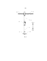
фиг. 5 — схематическое изображение телескопического элемента устройства для выравнивания сегментов обделки тоннеля относительно друг друга, применяемого в проходческой машине, согласно вариантам осуществления настоящего изобретения;FIG. 5 is a schematic illustration of a telescopic element of a device for aligning tunnel lining segments with respect to each other used in a tunneling machine, according to embodiments of the present invention;
фиг. 6 — схематическое изображение первой опорной рамы устройства для выравнивания сегментов обделки тоннеля относительно друг друга, применяемого в проходческой машине, согласно вариантам осуществления настоящего изобретения;FIG. 6 is a schematic illustration of a first support frame of an apparatus for aligning tunnel lining segments with respect to each other used in a sinking machine, according to embodiments of the present invention;
фиг. 7 — схематическое изображение второй опорной рамы устройства для выравнивания сегментов обделки тоннеля относительно друг друга, применяемого в проходческой машине, согласно вариантам осуществления настоящего изобретения;FIG. 7 is a schematic illustration of a second support frame of a device for aligning tunnel lining segments with respect to each other used in a sinking machine, according to embodiments of the present invention;
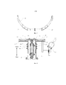
фиг. 8 — схематическое изображение подъемного элемента устройства для выравнивания сегментов обделки тоннеля относительно друг друга, применяемого в проходческой машине, согласно вариантам осуществления настоящего изобретения;FIG. 8 is a schematic illustration of a lifting member of a device for aligning tunnel lining segments with respect to each other used in a tunneling machine according to embodiments of the present invention;
фиг. 9 — схематическое изображение перемещенного устройства для выравнивания сегментов обделки тоннеля относительно друг друга, применяемого в проходческой машине, согласно вариантам осуществления настоящего изобретения;FIG. 9 is a schematic illustration of a displaced device for aligning tunnel lining segments with respect to each other used in a sinking machine, according to embodiments of the present invention;
фиг. 10 — схематическое изображение устройства для выравнивания сегментов обделки тоннеля относительно друг друга, применяемого в проходческой машине, согласно вариантам осуществления настоящего изобретения, на котором опорная рама поднята подъемным элементом;FIG. 10 is a schematic illustration of a device for aligning tunnel lining segments with respect to each other used in a tunneling machine, according to embodiments of the present invention, wherein the support frame is lifted by a lifting member;
фиг. 11 — схематическое изображение устройства для выравнивания сегментов обделки тоннеля относительно друг друга, применяемого в проходческой машине, согласно вариантам осуществления настоящего изобретения, на котором опорная рама поднята подъемным элементом и раскрыта телескопическими элементами;FIG. 11 is a schematic illustration of a device for aligning tunnel lining segments with respect to each other used in a tunneling machine, according to embodiments of the present invention, in which the support frame is lifted by a lifting member and disclosed by telescopic elements;
фиг. 12 — схематическое изображение подъемного элемента устройства для выравнивания сегментов обделки тоннеля относительно друг друга, применяемого в проходческой машине, согласно вариантам осуществления настоящего изобретения, на котором он отделен от опорной рамы;FIG. 12 is a schematic illustration of a lifting member of a device for aligning tunnel lining segments with respect to each other used in a sinking machine, according to embodiments of the present invention, in which it is separated from the support frame;
фиг. 13 — схематическое изображение поступательного перемещения устройства для выравнивания сегментов обделки тоннеля относительно друг друга проходческой машины согласно вариантам осуществления настоящего изобретения.FIG. 13 is a schematic illustration of the translational movement of a device for aligning tunnel lining segments with respect to each other in a tunneling machine according to embodiments of the present invention.
Ссылочные позиции в прилагаемых графических материалах:Reference positions in the attached graphic materials:
опорная рама 1, первая опорная рама 11, фиксирующие штифты 111, второе отверстие 112 под штифт, вторая опорная рама 12, упругие прокладки 13, выносные опоры 14, телескопические элементы 15, выдвигающий механизм 151, шарнирные пальцы 1511, выдвижной внутренний цилиндр 152, выдвижной наружный цилиндр 153, датчики 154 положения;
подъемный элемент 2, подъемный механизм 21, шарнирные пальцы 211, опорный внутренний цилиндр 22, опорный наружный цилиндр 23, направляющий элемент 24, масленки 241, болты 242, крепежный кронштейн 25, фиксирующие отверстия 251, бесконтактный выключатель 26, выключатель 27 отклонения;
предохранительный штифт 3, цепь 31;
монтажный механизм 200, опорная балка 201, рама 202, монтажная платформа 2021, приводной элемент 203, механизм 204 для захвата элементов сегмента обделки;
хвостовая часть 300 щита, приемная полость 301;
сегмент 400 обделки тоннеля, элемент 401 сегмента обделки.
Описание предпочтительных вариантов осуществленияDescription of Preferred Embodiments
Ниже подробно описаны варианты осуществления настоящего изобретения, при этом в прилагаемых графических материалах представлены примеры указанных вариантов осуществления. Нижеприведенные варианты осуществления, описанные со ссылками на прилагаемые графические материалы, являются примерами, предназначенными для объяснения настоящего изобретения, и их не следует рассматривать как ограничивающие настоящее изобретение.Embodiments of the present invention are described in detail below, while examples of these embodiments are provided in the accompanying drawings. The following embodiments, described with reference to the accompanying drawings, are examples intended to explain the present invention, and should not be construed as limiting the present invention.
Следует понимать, что по всему описанию направление или пространственное распределение, указанные с применением терминов «центральный», «продольный», «поперечный», «длина», «ширина», «толщина», «верхний», «нижний», «передний»», «задний», «левый», «правый», «вертикальный», «горизонтальный», «верхний», «нижний», «внутри», «снаружи», «по часовой стрелке», «против часовой стрелки», «продольное направление», «радиальное направление», «направление вдоль окружности» и т. п., представляют собой направление или пространственное распределение, указанные согласно прилагаемым графическим материалам, приведенные только для удобства и простоты описания настоящего изобретения и не указывающие или означающие то, что указываемые устройство или элементы обязательно должны быть направлены определенным образом, а также компоноваться или применяться в определенном направлении, поэтому их не следует рассматривать как ограничивающие настоящее изобретение.It should be understood that throughout the description, the direction or spatial distribution indicated using the terms “central”, “longitudinal”, “transverse”, “length”, “width”, “thickness”, “upper”, “lower”, “front” "", "Back", "left", "right", "vertical", "horizontal", "upper", "lower", "inside", "outside", "clockwise", "counterclockwise" , "Longitudinal direction", "radial direction", "circumferential direction", etc., represent a direction or spatial distribution, shown according to the attached graphic materials, given only for the convenience and simplicity of the description of the present invention and not indicating or meaning that the indicated device or elements must necessarily be directed in a certain way, as well as be arranged or applied in a certain direction, therefore they should not be construed as limiting the present invention.
Кроме того, термины «первый» и «второй» применяются только в целях описания, и их не следует рассматривать как указывающие или намекающие на относительную значимость или предполагаемое количество технических признаков, которое следует указать. Таким образом, признаки, ограниченные наличием слов «первый» и «второй», могут прямо или косвенно означать по меньшей мере один указанный признак. По всему описанию термин «несколько» подразумевает по меньшей мере два, например, два, три и т. п., если ясно не определено другое.In addition, the terms “first” and “second” are used for description purposes only and should not be construed as indicating or alluding to the relative importance or estimated number of technical features that should be indicated. Thus, features limited by the presence of the words “first” and “second” may directly or indirectly mean at least one of the indicated feature. Throughout the description, the term “several” means at least two, for example, two, three, etc., unless clearly defined otherwise.
В настоящем изобретении, если только точно не определено или установлено иное, термины «установить», «сопрягать», «соединять», «закреплять» и другие термины необходимо понимать в широком смысле, например, может быть жесткое соединение, а также может быть соединение с возможностью отсоединения или соединение как одно целое; может быть механическое соединение, а также может быть электрическое соединение или оба таких соединения; может быть непосредственное соединение, а также может быть опосредованное, непрямое соединение; и может быть сообщение внутри двух элементов или может быть отношение взаимодействия между двумя элементами, если только точно не установлено иное. Конкретный смысл вышеуказанных терминов в настоящем изобретении будет понятен специалистам в данной области техники на основании конкретных случаев.In the present invention, unless otherwise specifically defined or established otherwise, the terms “establish”, “match”, “connect”, “fasten” and other terms must be understood in a broad sense, for example, there may be a rigid connection, and there may also be a connection with the possibility of detachment or connection as a whole; there may be a mechanical connection, and there may also be an electrical connection, or both; there may be a direct connection, and there may also be an indirect, indirect connection; and there may be a message within the two elements, or there may be a relationship of interaction between the two elements, unless otherwise specifically stated. The specific meaning of the above terms in the present invention will be clear to those skilled in the art based on specific cases.
Ниже, как видно на фиг. 1—13, представлено устройство для выравнивания сегментов обделки тоннеля относительно друг друга, применяемое в проходческой машине, согласно вариантам осуществления настоящего изобретения.Below, as seen in FIG. 1-13, an apparatus for aligning tunnel lining segments relative to each other, used in a tunneling machine, according to embodiments of the present invention, is provided.
На фиг. 1—13 показано устройство для выравнивания сегментов обделки тоннеля относительно друг друга, применяемое в проходческой машине, согласно вариантам осуществления первого аспекта настоящего изобретения, при этом в проходческой машине предусмотрен монтажный механизм 200, выполненный с возможностью перемещения в продольном направлении тоннеля (на фиг. 1 это направление вперед или назад). При этом термин «продольное направление тоннеля» означает направление прохождения тоннеля.In FIG. 1-13, an apparatus for aligning tunnel lining segments relative to each other, used in a tunneling machine, according to embodiments of the first aspect of the present invention, is shown in the tunneling machine with a mounting
В частности, монтажный механизм 200 предназначен для монтажа сегментов 400 обделки тоннеля, и внутреннюю стенку тоннеля получают путем последовательного соединения множества элементов 401 сегмента обделки, при этом после того, как монтажный механизм 200 соединяет множество элементов 401 сегмента обделки в сегмент 400 обделки тоннеля, который соответствует внешнему контуру тоннеля, он может путем цементации прикреплять полученный таким образом сегмент 400 обделки тоннеля к тоннелю, чтобы получить внутреннюю стенку тоннеля. Устройство для выравнивания сегментов обделки тоннеля относительно друг друга и монтажный механизм 200 расположены в продольном направлении тоннеля, и монтажный механизм 200 снабжен подъемным элементом 2, выполненным с возможностью вытягивания и втягивания в направлении вверх и вниз соответственно. Монтажный механизм 200 может быть снабжен монтажной платформой 2021, и подъемный элемент 2 может быть прикреплен к монтажной платформе 2021. Например, подъемный элемент 2 может быть приварен к монтажной платформе 2021, а также может быть прикреплен к монтажной платформе 2021 посредством крепежных элементов.In particular, the mounting
Устройство для выравнивания сегментов обделки тоннеля относительно друг друга содержит опорную раму 1, и при работе устройства для выравнивания сегментов обделки тоннеля относительно друг друга опорная рама 1 поддерживает по меньшей мере часть из множества элементов 401 сегмента обделки для выравнивания формы тоннеля. Разумеется, в зависимости от фактических требований опорная рама 1 может поддерживать часть из множества элементов 401 сегмента обделки для выравнивания взаимного положения указанной части элементов 401 сегментов обделки, при этом устройство для выравнивания сегментов обделки тоннеля относительно друг друга осуществляет выравнивание части тоннеля. Или опорная рама 1 может поддерживать все элементы 401 сегмента обделки, и, таким образом, осуществляется выравнивание формы всего тоннеля, чтобы придать ему заранее установленную форму. Следовательно, выравнивание посредством устройства для выравнивания сегментов обделки тоннеля относительно друг друга может предотвращать изменение формы тоннеля, вызванное неравномерностью цементации, а также геологическими и прочими причинами, что обеспечивает выполнение тоннеля заранее установленной формы, и, таким образом, обеспечивается качественное возведение тоннеля; в то же время также может обеспечиваться эффективность строительных работ. Кроме того, форма опорной рамы 1 может определяться формой тоннеля. Например, если внутренняя окружность тоннеля является в целом круглой, то форма внешней окружности опорной рамы 1 согласуется с формой внутренней окружности тоннеля. При необходимости опорная рама 1 может представлять собой стальную раму.The device for aligning the tunnel lining segments with respect to each other comprises a
Кроме того, в опорной раме 1 установлены фиксирующие штифты 111, при этом фиксирующие штифты 111 могут быть установлены в поверхности внутренней стенки в верхней части опорной рамы 1, например, фиксирующие штифты 111 могут быть приварены к опорной раме 1. При необходимости количество фиксирующих штифтов 111 может составлять два, при этом два фиксирующих штифта 111 могут быть установлены на расстоянии друг от друга в направлении ширины тоннеля. В подъемном элементе 2 выполнены фиксирующие отверстия 251, предназначенные для ввода в зацепление фиксирующих штифтов 111, при этом фиксирующие отверстия 251 могут быть выполнены в верхней части подъемного элемента 2, что делает удобным ввод фиксирующих штифтов 111 в зацепление в фиксирующих отверстиях 251 и вывод из него. Кроме того, термин «направление ширины тоннеля» означает направление, проходящее перпендикулярно продольному направлению тоннеля в горизонтальной плоскости.In addition, the fixing pins 111 are installed in the
В частности, при работе устройства для выравнивания сегментов обделки тоннеля относительно друг друга сначала за счет перемещения монтажного механизма 200 обеспечивается перемещение подъемного элемента 2 к месту, в котором он будет расположен параллельно устройству для выравнивания сегментов обделки тоннеля относительно друг друга, а затем фиксирующие штифты 111 в опорной раме 1 вводят в зацепление с фиксирующими отверстиями 251 в подъемном элементе 2. Затем подъемный элемент 2 вытягивается вверх в первое заданное положение, чтобы фиксирующие штифты 111 вошли в фиксирующие отверстия 251 для зацепления, при этом обеспечивается соединение устройства для выравнивания сегментов обделки тоннеля относительно друг друга с подъемным элементом 2, и, таким образом, посредством подъемного элемента 2 обеспечивается соединение устройства для выравнивания сегментов обделки тоннеля относительно друг друга с монтажным механизмом 200. После того как устройство для выравнивания сегментов обделки тоннеля относительно друг друга отсоединится от вышеуказанного сегмента 400 обделки тоннеля, подъемный элемент 2 втягивается во второе заданное положение, и в процессе этого фиксирующие штифты 111 остаются в зацеплении в фиксирующих отверстиях 251. Монтажный механизм 200 перемещается в обратном направлении в место, в котором тоннель необходимо выровнять, и, таким образом, за счет перемещения монтажного механизма 200 происходит перемещение устройства для выравнивания сегментов обделки тоннеля относительно друг друга, при этом нет необходимости в отдельном источнике питания, предназначенном для перемещения устройства для выравнивания сегментов обделки тоннеля относительно друг друга, уменьшается количество комплектующих, снижается себестоимость и может обеспечиваться еще более простая и компактная конструкция.In particular, when the device is used to align the tunnel lining segments relative to each other, first by moving the mounting
После того как устройство для выравнивания сегментов обделки тоннеля относительно друг друга перемещается к месту монтажа в тоннеле, подъемный элемент 2 вытягивается вверх в вышеуказанное первое заданное положение и одновременно перемещает опорную раму 1 вверх, чтобы опорная рама 1 поддерживала сегмент 400 обделки тоннеля, и, таким образом, происходит восстановление формы тоннеля. Разумеется, сама опорная рама 1, кроме того, может быть также выполнена с возможностью втягивания и вытягивания, и после вытягивания вверх подъемного элемента 2 для обеспечения поддерживания опорной рамой 1 сегмента 400 обделки тоннеля на внутренней стенке тоннеля внешняя окружность опорной рамы 1 может увеличиваться в высоту, чтобы опорная рама 1 поддерживала больше элементов 401 сегмента обделки или все элементы 401 сегмента обделки, а также может обеспечиваться устойчивость устройства для выравнивания сегментов обделки тоннеля относительно друг друга во время восстановления формы тоннеля, и, таким образом, тоннель получают заранее установленной формы. Следует отметить то, что во время восстановления формы тоннеля посредством устройства для выравнивания сегментов обделки тоннеля относительно друг друга устройство для выравнивания сегментов обделки тоннеля относительно друг друга посредством опорной рамы 1 поддерживает сегмент 400 обделки тоннеля, а также обеспечивает ему опору и устойчивость.After the device for aligning the tunnel lining segments relative to each other moves to the installation site in the tunnel, the lifting
После того как подъемный элемент 2 вытягивается вверх в первое заданное положение, чтобы опорная рама 1 поддерживала сегмент 400 обделки тоннеля на внутренней стенке тоннеля, подъемный элемент 2 может втягиваться вниз, при этом фиксирующие штифты 111 на опорной раме 1 выходят из зацепления с фиксирующими отверстиями 251 в подъемном элементе 2, то есть подъемный элемент 2 отделяется от устройства для выравнивания сегментов обделки тоннеля относительно друг друга, а опорная рама 1 продолжает поддерживать сегмент 400 обделки тоннеля. После того как подъемный элемент 2 втягивается вниз в третье заданное положение, монтажный механизм 200 может перемещаться вперед, чтобы продолжать соединять сегменты 400 обделки тоннеля, при этом подъемный элемент 2 перемещается вперед вместе с монтажным механизмом 200. После того как монтажный механизм 200 соединит сегменты 400 обделки тоннеля на участке, он повторяет вышеуказанный процесс, чтобы подкорректировать форму сегментов 400 обделки тоннеля на новом участке. Кроме того, термин «вперед» означает направление забоя тоннеля; термин «назад» означает направление, противоположное направлению «вперед», то есть направление от забоя тоннеля.After the
Следует отметить то, что отношение вышеуказанных первого заданного положения, второго заданного положения и третьего заданного положения друг к другу заключается в том, что второе заданное положение ниже, чем первое заданное положение, и выше, чем третье заданное положение.It should be noted that the ratio of the aforementioned first predetermined position, second predetermined position and third predetermined position to each other is that the second predetermined position is lower than the first predetermined position and higher than the third predetermined position.
В устройстве для выравнивания сегментов обделки тоннеля относительно друг друга, применяемом в проходческой машине, согласно вариантам осуществления настоящего изобретения за счет перемещения монтажного механизма 200 в проходческой машине осуществляется перемещение устройства для выравнивания сегментов обделки тоннеля относительно друг друга, и, таким образом, можно исключить необходимость в отдельном источнике питания, применяемом для перемещения устройства для выравнивания сегментов обделки тоннеля относительно друг друга, и, следовательно, можно снизить себестоимость и одновременно обеспечить качественное возведение тоннеля и эффективность строительных работ, а также оно обладает такими преимуществами, как простота и компактность конструкции.In the device for aligning the tunnel lining segments relative to each other, used in a tunneling machine, according to embodiments of the present invention, by moving the mounting
В некоторых вариантах осуществления настоящего изобретения, как видно на фиг. 3 и фиг. 9—12, устройство для выравнивания сегментов обделки тоннеля относительно друг друга дополнительно содержит предохранительный штифт 3, при этом предохранительный штифт 3 предназначен для соединения подъемного элемента 2 с опорной рамой 1, чтобы закрепить опорную раму 1 на подъемном элементе 2. В частности, после того как монтажный механизм 200 перемещается к месту, в котором он будет расположен параллельно устройству для выравнивания сегментов обделки тоннеля относительно друг друга, и фиксирующие штифты 111 на опорной раме 1 входят в зацепление с фиксирующими отверстиями 251 в подъемном элементе 2, посредством предохранительного штифта 3 осуществляется дополнительная фиксация опорной рамы 1 на подъемном элементе 2, и, таким образом, можно обеспечить более прочное соединение опорной рамы 1 с подъемным элементом 2, предотвратить колебание устройства для выравнивания сегментов обделки тоннеля относительно друг друга, возникающее в процессе перемещения монтажного механизма 200, или падение устройства для выравнивания сегментов обделки тоннеля относительно друг друга, вызванное отсоединением устройства для выравнивания сегментов обделки тоннеля относительно друг друга от подъемного элемента 2 при воздействии внешних сил, что исключает существующую потенциальную угрозу безопасности и, кроме того, обеспечивает безопасность и надежность при эксплуатации оборудования и техническом обслуживании. И после того, как устройство для выравнивания сегментов обделки тоннеля относительно друг друга посредством монтажного механизма 200 перемещается к месту монтажа в тоннеле и посредством подъемного элемента 2 поднимается в первое заданное положение, при этом одновременно перемещается вверх опорная рама 1, и опорная рама 1 за счет увеличения в размерах или иным образом поддерживает и стабилизирует сегмент 400 обделки тоннеля, предохранительный штифт 3 можно удалить, чтобы подъемный элемент 2 и опорная рама 1 вышли из зацепления друг с другом, и, следовательно, подъемный элемент 2 можно было плавно втянуть.In some embodiments of the present invention, as seen in FIG. 3 and FIG. 9-12, the device for aligning the tunnel lining segments with respect to each other further comprises a
Например, в определенных вариантах осуществления настоящего изобретения, как видно на фиг. 3, фиг. 6 и фиг. 8, на верхнем конце подъемного элемента 2 предусмотрен крепежный кронштейн 25, при этом фиксирующие отверстия 251 выполнены в крепежном кронштейне 25 для удобства выполнения фиксирующих отверстий 251 и, таким образом, для удобства ввода фиксирующих штифтов 111 в зацепление с фиксирующими отверстиями 251 и вывода из него. В опорной раме 1 выполнено первое отверстие под штифт, а в крепежном кронштейне 25 дополнительно выполнено второе отверстие 112 под штифт, и один конец предохранительного штифта 3 соединен с крепежным кронштейном 25, а другой конец проходит через первое отверстие под штифт и второе отверстие 112 под штифт для закрепления опорной рамы 1 на подъемном элементе 2. Следовательно, посредством предохранительного штифта 3 закреплять опорную раму 1 на подъемном элементе 2, чтобы предотвратить колебание, возникающее в процессе перемещения устройства для выравнивания сегментов обделки тоннеля относительно друг друга, удобно, и при удалении предохранительного штифта 3 необходимо лишь вытащить предохранительный штифт 3, чтобы извлечь предохранительный штифт 3 из первого отверстия под штифт и второго отверстия 112 под штифт, и, таким образом, заставить подъемный элемент 2 и опорную раму 1 выйти из зацепления друг с другом, что делает применение предохранительного штифта 3 удобным. Кроме того, один конец предохранительного штифта 3 соединен с крепежным кронштейном 25, например, вышеуказанный один конец предохранительного штифта 3 может быть соединен с крепежным кронштейном 25 посредством цепи 31, при этом один конец цепи 31 соединен с вышеуказанным одним концом предохранительного штифта 3 сваркой, а ее другой конец соединен сваркой с крепежным кронштейном 25, и, следовательно, может предотвращаться падение или потеря предохранительного штифта 3. For example, in certain embodiments of the present invention, as seen in FIG. 3, FIG. 6 and FIG. 8, a fixing
В некоторых вариантах осуществления настоящего изобретения, как видно на фиг. 3, фиг. 6, фиг. 7 и фиг. 9—12, опорная рама 1 содержит первую опорную раму 11 и вторую опорную раму 12, расположенные вверху и внизу и соединенные друг с другом. При необходимости первая опорная рама 11 и вторая опорная рама 12 в целом могут быть выполнены полукруглыми, при этом первая опорная рама 11 открыта вниз, а вторая опорная рама 12 открыта вверх. Два конца первой опорной рамы 11 соединены соответственно с двумя концами второй опорной рамы 12 посредством телескопических элементов 15, при этом когда телескопические элементы 15 вытягиваются, то опорная рама 1 осуществляет выравнивание формы тоннеля. В частности, после того как подъемный элемент 2 вытягивается вверх в первое заданное положение и одновременно поднимает опорную раму 1, опорная рама 1 поддерживает верхнюю часть сегмента 400 обделки тоннеля, и затем можно посредством вытягивания установленных на опорной раме 1 телескопических элементов 15 обеспечить перемещение первой опорной рамы 11 и второй опорной рамы 12 относительно друг друга, и, таким образом, можно увеличить размер опорной рамы 1, чтобы опорная рама 1 лучше поддерживала сегмент 400 обделки тоннеля, например, чтобы опорная рама 1 могла полностью поддерживать сегмент 400 обделки тоннеля, и обеспечить устойчивость устройства для выравнивания сегментов обделки тоннеля относительно друг друга в процессе восстановления формы тоннеля, и, таким образом, можно привести форму тоннеля к заранее установленной форме и обеспечить качественное возведение тоннеля. При необходимости на внешней круговой поверхности первой опорной рамы 11 и внешней круговой поверхности второй опорной рамы 12 соответственно могут быть предусмотрены упругие прокладки 13, и, следовательно, когда опорная рама 1 при увеличении в размерах поддерживает сегмент 400 обделки тоннеля, можно предотвратить повреждение опорной рамой 1 сегмента 400 обделки тоннеля.In some embodiments of the present invention, as seen in FIG. 3, FIG. 6, FIG. 7 and FIG. 9-12, the
Следует отметить то, что при перемещении устройства для выравнивания сегментов обделки тоннеля относительно друг друга вместе с монтажным механизмом 200 телескопические элементы 15 пребывают во втянутом состоянии для удобства перемещения устройства для выравнивания сегментов обделки тоннеля относительно друг друга и возможности обеспечения устойчивости и безопасности в процессе перемещения оборудования.It should be noted that when moving the device for aligning the tunnel lining segments relative to each other together with the mounting
Кроме того, в определенных вариантах осуществления настоящего изобретения, как видно на фиг. 3 и фиг. 5, телескопические элементы 15 содержат выдвигающий механизм 151, выдвижной внутренний цилиндр 152 и выдвижной наружный цилиндр 153, последовательно расположенные изнутри наружу. Один конец выдвигающего механизма 151 (как видно на фиг. 5, верхний конец выдвигающего механизма 151) соединен с первой опорной рамой 11, а другой конец выдвигающего механизма 151 (как видно на фиг. 5, нижний конец выдвигающего механизма 151) соединен со второй опорной рамой 12, например, вышеуказанные два конца выдвигающего механизма 151 могут быть соединены соответственно с первой опорной рамой 11 и второй опорной рамой 12 посредством шарнирных пальцев 1511. Один конец выдвижного внутреннего цилиндра 152 (как видно на фиг. 5, верхний конец выдвижного внутреннего цилиндра 152) соединен с первой опорной рамой 11, а другой конец выдвижного внутреннего цилиндра 152 (как видно на фиг. 5, нижний конец выдвижного внутреннего цилиндра 152) представляет собой свободный конец; например, вышеуказанный один конец выдвижного внутреннего цилиндра 152 может быть соединен с первой опорной рамой 11 посредством болтов. Один конец выдвижного наружного цилиндра 153 (как видно на фиг. 5, нижний конец выдвижного наружного цилиндра 153) соединен со второй опорной рамой 12, а другой конец выдвижного наружного цилиндра 153 (как видно на фиг. 5, верхний конец выдвижного наружного цилиндра 153) представляет собой свободный конец; например, вышеуказанный один конец выдвижного наружного цилиндра 153 может быть соединен со второй опорной рамой 12 посредством болтов.In addition, in certain embodiments of the present invention, as seen in FIG. 3 and FIG. 5, the
Кроме того, свободный конец выдвижного внутреннего цилиндра 152 может перемещаться вверх и вниз относительно свободного конца выдвижного наружного цилиндра 153. Следовательно, когда выдвигающий механизм 151 выдвигается вверх, то свободный конец выдвижного внутреннего цилиндра 152 перемещается вверх относительно свободного конца выдвижного наружного цилиндра 153, и, таким образом, обеспечивается вытягивание всех телескопических элементов 15, а также обеспечивается увеличение размера опорной рамы 1; когда выдвигающий механизм 151 втягивается вниз, то свободный конец выдвижного внутреннего цилиндра 152 перемещается вниз относительно свободного конца выдвижного наружного цилиндра 153, и, таким образом, обеспечивается втягивание всех телескопических элементов 15, а также обеспечивается возврат опорной рамы 1 в исходное состояние. Кроме того, конструкция таких телескопических элементов 15 является простой и легко осуществляет вытягивание и втягивание. При необходимости выдвигающий механизм 151 может представлять собой гидроцилиндр, пневмоцилиндр или линейный исполнительный механизм с электрическим приводом.In addition, the free end of the sliding
В некоторых вариантах осуществления настоящего изобретения, как видно на фиг. 3, на телескопических элементах 15 предусмотрены датчики 154 положения, предназначенные для определения положения телескопических элементов 15 при вытягивании и втягивании. Следовательно, посредством датчиков 154 положения определяется положение телескопических элементов 15 при вытягивании и втягивании, и, с одной стороны, можно определить, достигли ли телескопические элементы 15 определенного положения при вытягивании или определенного положения при втягивании, чтобы обеспечить стабильную и надежную работу устройства для выравнивания сегментов обделки тоннеля относительно друг друга, а также обеспечить качественное возведение тоннеля; а с другой стороны — на основании информации об определенном положении, полученной от датчиков 154 положения, можно точно контролировать процесс работы устройства для выравнивания сегментов обделки тоннеля относительно друг друга.In some embodiments of the present invention, as seen in FIG. 3,
Например, после того как подъемный элемент 2 перемещается к месту, в котором он будет расположен параллельно устройству для выравнивания сегментов обделки тоннеля относительно друг друга, и подъемный элемент 2 вытягивается вверх в первое заданное положение, чтобы фиксирующие штифты 111 вошли в фиксирующие отверстия 251 для зацепление с ними, за счет втягивания телескопических элементов 15 опорная рама 1 отделяется от сегментов 400 обделки тоннеля, и после того как датчики 154 положения определяют, что телескопические элементы 15 достигли определенного положения при втягивании, управление втягиванием подъемного элемента 2 происходит так, чтобы предотвращалось падение устройства для выравнивания сегментов обделки тоннеля относительно друг друга из-за потери опоры и обеспечивалась стабильная работа устройства для выравнивания сегментов обделки тоннеля относительно друг друга.For example, after the
В другом примере, после того как устройство для выравнивания сегментов обделки тоннеля относительно друг друга перемещается к месту монтажа в тоннеле, подъемный элемент 2 вытягивается вверх в первое заданное положение, чтобы опорная рама 1 поддерживала сегмент 400 обделки тоннеля верхней части, и за счет вытягивания телескопических элементов 15 увеличивается размер опорной рамы 1, чтобы опорная рама 1 лучше или полностью поддерживала сегмент 400 обделки тоннеля, при этом устройство для выравнивания сегментов обделки тоннеля относительно друг друга за счет поддерживания сегмента 400 обделки тоннеля обеспечивает ему опору и устойчивость. После того как датчики 154 положения определяют, что телескопические элементы 15 достигли определенного положения при вытягивании, может осуществляться управление втягиванием подъемного элемента 2 вниз, чтобы предотвратить падение устройства для выравнивания сегментов обделки тоннеля относительно друг друга из-за потери опоры, и обеспечивается стабильная работа устройства для выравнивания сегментов обделки тоннеля относительно друг друга.In another example, after the device for aligning the tunnel lining segments relative to each other moves to the installation site in the tunnel, the lifting
В некоторых вариантах осуществления настоящего изобретения, как видно на фиг. 8, подъемный элемент 2 содержит подъемный механизм 21, опорный внутренний цилиндр 22 и опорный наружный цилиндр 23, последовательно расположенные изнутри наружу. Нижняя часть опорного наружного цилиндра 23 соединена с монтажным механизмом 200; один конец подъемного механизма 21 (как видно на фиг. 8, верхний конец подъемного механизма 21) соединен с опорным внутренним цилиндром 22, а другой конец подъемного механизма 21 (как видно на фиг. 8, нижний конец подъемного механизма 21) соединен с опорным наружным цилиндром 23; например, вышеуказанные два конца подъемного механизма 21 могут быть соответственно соединены с опорным внутренним цилиндром 22 и опорным наружным цилиндром 23 посредством шарнирных пальцев 211, при этом свободный конец опорного внутреннего цилиндра 22 может перемещаться вверх и вниз относительно свободного конца опорного наружного цилиндра 23. Следовательно, когда подъемный механизм 21 поднимается вверх, то свободный конец опорного внутреннего цилиндра 22 перемещается вверх относительно свободного конца опорного наружного цилиндра 23, и, таким образом, подъемный элемент 2 вытягиваться вверх; когда подъемный механизм 21 втягивается вниз, то свободный конец опорного внутреннего цилиндра 22 перемещается вниз относительно свободного конца опорного наружного цилиндра 23, и, таким образом, подъемный элемент 2 втягиваться вниз. При необходимости подъемный механизм 21 представляет собой гидроцилиндр, пневмоцилиндр или линейный исполнительный механизм с электрическим приводом.In some embodiments of the present invention, as seen in FIG. 8, the lifting
Кроме того, как видно на фиг. 8, между опорным внутренним цилиндром 22 и опорным наружным цилиндром 23 может быть предусмотрен направляющий элемент 24, при этом направляющий элемент 24 соединен с одним из опорного наружного цилиндра 23 и опорного внутреннего цилиндра 22 и может скользить вверх и вниз относительно другого из опорного наружного цилиндра 23 и опорного внутреннего цилиндра 22. Например, если направляющий элемент 24 соединен с опорным наружным цилиндром 23, то направляющий элемент 24 может скользить вверх и вниз относительно опорного внутреннего цилиндра 22; если направляющий элемент 24 соединен с опорным внутренним цилиндром 22, то направляющий элемент 24 может скользить вверх и вниз относительно опорного наружного цилиндра 23. Следовательно, направление посредством направляющего элемента 24 относительного движения между опорным внутренним цилиндром 22 и опорным наружным цилиндром 23 может обеспечить стабильное вытягивание и втягивание подъемного элемента 2. При необходимости в месте, в котором опорный наружный цилиндр 23 соединен с направляющим элементом 2, могут предусматриваться масленки 241, и посредством масленок 241 в направлении направляющего элемента 24 может течь смазочное вещество, что обеспечивает подачу смазки между направляющим элементом 24 и опорным внутренним цилиндром 22.In addition, as seen in FIG. 8, a
При необходимости опорный внутренний цилиндр 22 и опорный наружный цилиндр 23 могут быть выполнены в виде круглых трубок или квадратных трубок. Если опорный внутренний цилиндр 22 и опорный наружный цилиндр 23 выполнены в виде квадратных трубок, то направляющих элементов 24 может быть четыре, при этом четыре направляющих элемента 24 соответственно установлены на соответствующих четырех сторонах опорного внутреннего цилиндра 22 и опорного наружного цилиндра 23.If necessary, the supporting
В определенных вариантах настоящего изобретения, как видно на фиг. 8, направляющий элемент 24 соединен с опорным наружным цилиндром 23 и может скользить вверх и вниз относительно опорного внутреннего цилиндра 22, при этом промежуток между направляющим элементом 24 и опорным внутренним цилиндром 22 можно регулировать. Следовательно, за счет регулирования промежутка между направляющим элементом 24 и опорным внутренним цилиндром 22 величина промежутка остается в приемлемых пределах, и, таким образом, направляющий элемент 24 лучше выполняет функцию направления. Например, направляющий элемент 24 может быть соединен с опорным наружным цилиндром 23 посредством болтов 242, и путем регулирования болтов 242 можно регулировать промежуток между направляющим элементом 24 и опорным внутренним цилиндром 22, что делает удобным регулирование промежутка между направляющим элементом 24 и опорным внутренним цилиндром 22.In certain embodiments of the present invention, as seen in FIG. 8, the
Разумеется, если промежуток между опорным внутренним цилиндром 22 и опорным наружным цилиндром 23 сравнительно мал, то вышеуказанный направляющий элемент 24 между опорным внутренним цилиндром 22 и опорным наружным цилиндром 23 может не предусматриваться, и в процессе перемещения опорного внутреннего цилиндра 22 внутренняя круговая поверхность опорного наружного цилиндра 23 может выполнять функцию направляющей при перемещении опорного внутреннего цилиндра 22.Of course, if the gap between the supporting
В некоторых вариантах осуществления настоящего изобретения, как показано на фиг. 3, на подъемном элементе 2 предусмотрен бесконтактный выключатель 26, предназначенный для определения положения подъемного элемента 2 при вытягивании и втягивании. Посредством установленного бесконтактного выключателя 26 определяют положение подъемного элемента 2 при вытягивании и втягивании, чтобы определить, достигли ли телескопические элементы 15 определенного положения при вытягивании и втягивании, что способствует точному контролю за процессом работы устройства для выравнивания сегментов обделки тоннеля относительно друг друга и обеспечивает стабильную, безопасную и надежную работу оборудования. Например, на подъемном элементе 2 может быть установлено три бесконтактных выключателя 26, при этом три бесконтактных выключателя 26 представляют собой первый бесконтактный выключатель, второй бесконтактный выключатель и второй бесконтактный выключатель соответственно.In some embodiments of the present invention, as shown in FIG. 3, a
Кроме того, первый бесконтактный выключатель может быть предназначен для определения того, вытянулся ли подъемный элемент 2 вверх в вышеуказанное первое заданное положение. В частности, после того как подъемный элемент 2 перемещается к месту, в котором он будет расположен параллельно устройству для выравнивания сегментов обделки тоннеля относительно друг друга, и подъемный элемент 2 вытягивается вверх в первое заданное положение, чтобы фиксирующие штифты 111 вошли в фиксирующие отверстия 251 для зацепления, посредством первого бесконтактного выключателя можно определить, поднялся ли подъемный элемент 2 в первое заданное положение, и посредством первого бесконтактного выключателя определяется, вытянулся ли подъемный элемент 2 вверх в первое заданное положение, при этом в сочетании с датчиками 154 положения одновременно определяется, находятся ли телескопические элементы 15 в положении, в котором они вытянуты, и управление втягиванием телескопических элементов 15 осуществляется так, чтобы отделить опорную раму 1 от сегмента 400 обделки тоннеля. После того как устройство для выравнивания сегментов обделки тоннеля относительно друг друга перемещается к месту монтажа в тоннеле, подъемный элемент 2 вытягивается вверх в первое заданное положение, чтобы опорная рама 1 поддерживала сегмент 400 обделки тоннеля верхней части, при этом посредством первого бесконтактного выключателя можно определить, поднялся ли подъемный элемент 2 в первое заданное положение, и посредством первого бесконтактного выключателя определяется, вытянулся ли подъемный элемент 2 вверх в первое заданное положение, при этом в сочетании с датчиками 154 положения одновременно определяется, находятся ли телескопические элементы 15 в положении, в котором они втянуты, и осуществляется управление вытягиванием телескопических элементов 15, чтобы опорная рама 1 полностью поддерживала сегмент 400 обделки тоннеля. Благодаря установленному первому бесконтактному выключателю телескопические элементы 15 могут вытягиваться и втягиваться только в случае контроля за вытягиванием подъемного элемента 2 вверх в первое заданное положение, и, таким образом, обеспечивается защита оборудования от повреждения и безопасность операторов.In addition, the first proximity switch may be designed to determine whether the lifting
Кроме того, второй бесконтактный выключатель может быть предназначен для определения того, вытянулся ли подъемный элемент 2 вверх в вышеуказанное второе заданное положение. В частности, перед тем как устройство для выравнивания сегментов обделки тоннеля относительно друг друга посредством монтажного механизма 200 перемещается горизонтально, подъемный элемент 2 необходимо втянуть во второе заданное положение, при этом посредством второго бесконтактного выключателя можно определить, находится ли подъемный элемент 2 во втором заданном положении; посредством второго бесконтактного выключателя определяется, находится ли элемент во втором заданном положении, и осуществляется управление перемещением монтажного механизма 200; следовательно, можно обеспечить плавное перемещение устройства для выравнивания сегментов обделки тоннеля относительно друг друга вместе с монтажным механизмом 200 и предотвратить ситуацию, когда телескопические элементы 15 не достигают необходимого положения, и устройство для выравнивания сегментов обделки тоннеля относительно друг друга задевает внутреннюю стенку тоннеля.In addition, the second proximity switch may be designed to determine whether the lifting
Третий бесконтактный выключатель может быть предназначен для определения того, втянулся ли подъемный элемент 2 вниз в вышеуказанное третье заданное положение. В частности, после того как подъемный элемент 2 вытягивается вверх в первое заданное положение, чтобы опорная рама 1 поддерживала сегмент 400 обделки тоннеля верхней части, и за счет вытягивания телескопических элементов 15 увеличивается размер опорной рамы 1, чтобы опорная рама 1 полностью поддерживала сегмент 400 обделки тоннеля, и после того как посредством датчиков 154 положения определяется, достигли ли телескопические элементы 15 определенного положения при вытягивании, подъемный элемент 2 втягивается вниз в третье заданное положение, при этом посредством третьего бесконтактного выключателя можно определить, находится ли подъемный элемент 2 в третьем заданном положении; и посредством третьего бесконтактного выключателя определяется, находится ли подъемный элемент 2 в третьем заданном положении, и осуществляется управление перемещением монтажного механизма 200 вперед. Следовательно, можно обеспечить, чтобы подъемный элемент 2 находился сравнительно низко, а также обеспечить защиту оборудования от повреждения и экономию энергопотребления.The third proximity switch may be designed to determine whether the lifting
В некоторых вариантах осуществления настоящего изобретения, как видно на фиг. 3 и фиг. 8, на подъемном элементе 2 может быт предусмотрен выключатель 27 отклонения, предназначенный для определения расположения подъемного элемента 2 и опорной рамы 1 относительно друг друга. В частности, когда подъемный элемент 2 вытягивается вверх в первое заданное положение, посредством выключателя 27 отклонения определяется прилегание между подъемным элементом 2 и опорной рамой 1. Если подъемный элемент 2 прилегает к опорной раме 1, то управление устройством для выравнивания сегментов обделки тоннеля относительно друг друга осуществляется так, чтобы оно продолжало работать в установленном порядке; если между подъемным элементом 2 и опорной рамой 1 имеется сравнительно большой промежуток или они не прилегают друг к другу, то выключатель 27 отклонения подает сигнал, и управление устройством для выравнивания сегментов обделки тоннеля относительно друг друга осуществляется так, чтобы остановить его работу. Следовательно, можно обеспечить стабильную и надежную работу оборудования, а также обеспечить качественное возведение тоннеля.In some embodiments of the present invention, as seen in FIG. 3 and FIG. 8, a
В некоторых вариантах осуществления настоящего изобретения, как видно на фиг. 4, на опорной раме 1 предусмотрены выносные опоры 14, предназначенные для предотвращения опрокидывания опорной рамы 1, при этом выносные опоры 14 проходят в продольном направлении тоннеля. Следовательно, если из-за непредвиденного втягивания подъемного элемента 2, непредвиденного втягивания телескопических элементов 15, воздействия на опору рамы 1 больших внешних сил или по другим причинам устройство для выравнивания сегментов обделки тоннеля относительно друг друга теряет опору и может произойти его падение, то благодаря установленным выносным опорам 14 можно обеспечить сравнительно небольшой угол падения опорной рамы 1, и она сможет получить опору, например, опорная рама 1 сможет посредством выносных опор 14 опереться на внутреннюю стенку тоннеля и стабилизироваться, чтобы опорная рама 1 не продолжала падать вниз, и, таким образом, предотвращается опрокидывание устройства для выравнивания сегментов обделки тоннеля относительно друг друга и повреждение устройства для выравнивания сегментов обделки тоннеля относительно друг друга или повреждение монтажного механизма 200 и прочих элементов.In some embodiments of the present invention, as seen in FIG. 4,
Например, как показано на фиг. 4, количество выносных опор 14 составляет восемь, при этом четыре выносных опоры 14 установлены на верхнем конце опорной рамы 1, а остальные четыре выносных опоры 14 установлены на нижнем конце опорной рамы 1. Из четырех выносных опор 14, установленных на верхнем конце опорной рамы 1, две выносные опоры 14 находятся на передней стороне опорной рамы 1, а остальные две выносные опоры 14 находятся на задней стороне рамы; из четырех выносных опор 14, установленных на нижнем конце опорной рамы 1, две выносные опоры 14 находятся на передней стороне опорной рамы 1, а остальные две выносные опоры 14 находятся на задней стороне рамы. Следовательно, благодаря тому, что несколько выносных опор 14 равномерно и симметрично расположены на опорной раме 1, может обеспечиваться равновесие конструкции опорной рамы 1, а также может предотвращаться опрокидывание опорной рамы 1 при падении опорной рама 1 назад или вперед. При необходимости длина выносных опор 14, которые находятся на верхнем конце, может быть больше, чем длина выносных опор 14, которые находятся на нижнем конце, и, следовательно, может лучше предотвращаться опрокидывание опорной рамы 1.For example, as shown in FIG. 4, the number of
Ниже со ссылкой на фиг. 1 и фиг. 9—12 описан способ управления устройством для выравнивания сегментов обделки тоннеля относительно друг друга, применяемым в проходческой машине, согласно вариантам осуществления второго аспекта настоящего изобретения.Below with reference to FIG. 1 and FIG. 9-12, a method for controlling a device for aligning tunnel lining segments relative to each other used in a tunneling machine according to embodiments of the second aspect of the present invention is described.
Как видно на фиг. 9—12, в способе управления устройством для выравнивания сегментов обделки тоннеля относительно друг друга, применяемым в проходческой машине, согласно вариантам осуществления второго аспекта настоящего изобретения применяется устройство для выравнивания сегментов обделки тоннеля относительно друг друга, которое представляет собой устройство для выравнивания сегментов обделки тоннеля относительно друг друга согласно вариантам осуществления вышеуказанного первого аспекта настоящего изобретения, при этом указанный способ управления включает следующие этапы, на которых:As seen in FIG. 9-12, in a method for controlling a device for aligning tunnel lining segments with respect to each other used in a sinking machine, according to embodiments of the second aspect of the present invention, a device for aligning tunnel lining segments with respect to each other is used, which is a device for aligning tunnel lining segments with each other according to embodiments of the above first aspect of the present invention, wherein said method is controlled I includes the following steps:
S10 — после установки монтажным механизмом 200 N-го сегмента 400 обделки тоннеля сегмент 400 обделки тоннеля путем цементации прикрепляют к тоннелю для формирования внутренней стенки тоннеля; монтажный механизм 200 перемещают в первом направлении к месту N-1 сегмента 400 обделки тоннеля и устанавливают подъемный элемент 2 параллельно опорной раме 1 (см. фиг. 1 и фиг. 13); подъемный элемент 2 вытягивают вверх в первое заданное положение с введением фиксирующих штифтов 111 в фиксирующие отверстия 251 для зацепления (см. фиг. 10), затем соединяют устройство для выравнивания сегментов обделки тоннеля относительно друг друга с подъемным элементом 2 и, таким образом, посредством подъемного элемента 2 устройство для выравнивания сегментов обделки тоннеля относительно друг друга соединяют с монтажным механизмом 200. Кроме того, N≥2, при этом N представляет собой положительное целое число. Необходимо отметить, что термин «первое направление» означает направление, проходящее вверх относительно продольного направления забоя тоннеля, и направление назад, как показано на фиг. 13.S10 - after installation by the mounting
S20 — опорную раму 1 отделяют от N-1 сегмента 400 обделки тоннеля; например, могут осуществлять управление втягиванием опорной рамы 1, чтобы отделить опорную раму 1 от N-1 сегмента 400 обделки тоннеля (как видно на фиг. 9). Затем подъемный элемент 2 втягивают вниз во второе заданное положение, при этом второе заданное положение ниже, чем первое заданное положение. Следовательно, благодаря тому, что подъемный элемент 2 устанавливают во второе заданное положение, может обеспечиваться полное отделение опорной рамы 1 от N-1 сегмента 400 обделки тоннеля и предотвращаться ситуация, когда устройство для выравнивания сегментов обделки тоннеля относительно друг друга задевает сегмент 400 обделки тоннеля в процессе последующего перемещения.S20 — the
S30 — монтажный механизм 200 перемещают к месту N-го сегмента 400 обделки тоннеля во втором направлении, противоположном первому направлению (направление вперед, как показано на фиг. 13); подъемный элемент 2 вытягивают вверх в первое заданное положение, чтобы прижать в направлении вверх к опорной раме 1 (см. фиг. 10); опорная рама 1 поддерживает N-й сегмент 400 обделки тоннеля для выравнивания формы тоннеля (см. фиг. 11); например, могут увеличивать размер опорной рамы 1, чтобы опорная рама 1 поддерживала N-й сегмент 400 обделки тоннеля.S30 - the
S40 — подъемный элемент 2 втягивают вниз с выведением фиксирующих штифтов 111 из фиксирующих отверстий 251 (см. фиг. 12), при этом подъемный элемент 2 отделяют от устройства для выравнивания сегментов обделки тоннеля относительно друг друга, опорная рама 1 по-прежнему продолжает поддерживать N-й сегмент 400 обделки тоннеля и опорная рама 1 за счет того, что она поддерживает N-й сегмент 400 обделки тоннеля, обеспечивает ему стабильность; и устройство для выравнивания сегментов обделки тоннеля относительно друг друга восстанавливает форму тоннеля. Подъемный элемент 2 втягивают в третье заданное положение. Кроме того, третье заданное положение ниже, чем второе заданное положение.S40 - the
S50 — монтажный механизм 200 в вышеуказанном втором направлении перемещают к месту монтажа в тоннеле (см. фиг. 1 и фиг. 13), и посредством монтажного механизма 200 монтируют N+1 сегмент 400 обделки тоннеля. Разумеется, перед тем как монтажный механизм 200 монтирует N+1 сегмент 400 обделки тоннеля, проходческая машина осуществляет проходку, чтобы сформировать внутреннюю полость тоннеля.S50 — the mounting
S60 — повторяют вышеуказанные этапы S10—S50 до полного завершения тоннеля.S60 — repeat the above steps S10 — S50 until the tunnel is completed.
Способ управления устройством для выравнивания сегментов обделки тоннеля относительно друг друга, применяемым в проходческой машине, согласно вариантам осуществления настоящего изобретения может обеспечить качественное возведение тоннеля и эффективность строительных работ, а также может повысить защиту оборудования от повреждения и безопасность работников в процессе строительства.A method of controlling a device for aligning tunnel lining segments relative to each other, used in a tunneling machine, according to embodiments of the present invention, can provide high-quality tunnel construction and construction work efficiency, and can also improve equipment protection from damage and the safety of workers during the construction process.
В некоторых вариантах осуществления настоящего изобретения указанное устройство для выравнивания сегментов обделки тоннеля относительно друг друга содержит вышеуказанный предохранительный штифт 3, при этом указанный способ управления дополнительно включает следующие этапы, на которых: после этапа S10 и перед этапом S20 предохранительный штифт 3 закрепляют в опорной раме 1 и подъемном элементе 2, например, предохранительный штифт 3 вводят в первое отверстие под штифт в опорной раме 1 и второе отверстие 112 под штифт в подъемном элементе 2, чтобы закрепить опорную раму 1 на подъемном элементе 2, и, таким образом, может обеспечиваться более прочное соединение опорной рамы 1 с подъемным элементом 2, а также предотвращаться колебание устройства для выравнивания сегментов обделки тоннеля относительно друг друга, возникающее в процессе его перемещения вместе с монтажным механизмом 200, или опрокидывание устройства для выравнивания сегментов обделки тоннеля относительно друг друга, вызванное отделением устройства для выравнивания сегментов обделки тоннеля относительно друг друга от подъемного элемента 2 под действием внешних сил, что исключает существующую потенциальную угрозу безопасности и, кроме того, обеспечивает безопасность и надежность при эксплуатации оборудования и техническом обслуживании. После этапа S30 и перед этапом S40 предохранительный штифт 3 удаляют, чтобы подъемный элемент 2 и опорная рама 1 вышли из зацепления; например, предохранительный штифт 3 вытаскивают, чтобы вынуть предохранительный штифт 3 из первого отверстия под штифт в опорной раме 1 и второго отверстия 112 под штифт в подъемном элементе 2, и, следовательно, может обеспечиваться плавное втягивание подъемного элемента 2 в третье заданное положение.In some embodiments of the present invention, said apparatus for aligning tunnel lining segments with respect to each other comprises the
В некоторых вариантах осуществления настоящего изобретения опорная рама 1 снабжена телескопическими элементами 15, и, после того как на этапе S20 телескопические элементы 15 втягивают, чтобы отделить опорную раму 1 от N-1 сегмента 400 обделки тоннеля, и на этапе S30 подъемный элемент 2 вытягивают вверх в первое заданное положение, телескопические элементы 15 вытягивают, чтобы опорная рама 1 поддерживала N-й сегмент 400 обделки тоннеля для выравнивания формы тоннеля.In some embodiments of the present invention, the
Ниже со ссылкой на фиг. 1—13 описана проходческая машина согласно вариантам осуществления третьего аспекта настоящего изобретения.Below with reference to FIG. 1-13, a tunneling machine according to embodiments of the third aspect of the present invention is described.
Как показано на фиг. 1—13, проходческая машина согласно вариантам осуществления третьего аспекта настоящего изобретения содержит основную часть, опорную балку 201, монтажный механизм 200 и устройство для выравнивания сегментов обделки тоннеля относительно друг друга.As shown in FIG. 1-13, a sinking machine according to embodiments of the third aspect of the present invention comprises a main part, a
В частности, основная часть содержит хвостовую часть 300 щита, при этом в хвостовой части 300 щита предусмотрена приемная полость 301; опорная балка 201 установлена в приемной полости 301 и соединена с основной частью, при этом опорная балка 201 проходит в продольном направлении тоннеля. Монтажный механизм 200 предназначен для монтажа сегментов 400 обделки тоннеля, при этом монтажный механизм 200 расположен в приемной полости 301; монтажный механизм 200 установлен на опорной балке 201 и выполнен с возможностью перемещения вдоль опорной балки 201: например, монтажный механизм 200 может перемещаться горизонтально вперед, а также он может перемещаться горизонтально назад. В частности, монтажный механизм 200 содержит раму 202, а также механизм 204 для захвата элементов сегмента обделки, соединенный с рамой 202; рама 202 опирается на опорную балку 201, при этом рама 202 выполнена с возможностью перемещения вдоль опорной балки 201; механизм 204 для захвата элементов сегмента обделки может быть предназначен для захвата элемента 401 сегментов обделки и соединения элементов 401 сегмента обделки.In particular, the main part comprises a
Монтажный механизм 200 снабжен подъемным элементом 2, выполненным с возможностью вытягивания и втягивания в направлении вверх и вниз соответственно; на раме 202 монтажного механизма 200 установлена монтажная платформа 2021, и подъемный элемент 2 установлен на монтажной платформе 2021. Устройство для выравнивания сегментов обделки тоннеля относительно друг друга представляет собой устройство для выравнивания сегментов обделки тоннеля относительно друг друга, применяемое в проходческой машине, согласно вариантам осуществления вышеуказанного первого аспекта настоящего изобретения, и устройство для выравнивания сегментов обделки тоннеля относительно друг друга и монтажный механизм 200 расположены в продольном направлении тоннеля; устройство для выравнивания сегментов обделки тоннеля относительно друг друга содержит опорную раму 1, опорная рама 1 снабжена фиксирующими штифтами 111, и в подъемном элементе 2 выполнены фиксирующие отверстия 251, предназначенные для зацепления с фиксирующими штифтами 111. Следовательно, за счет перемещения монтажного механизма 200 в проходческой машине осуществляется перемещение устройства для выравнивания сегментов обделки тоннеля относительно друг друга, и, таким образом, можно исключить необходимость в отдельном источнике питания, применяемом для перемещения устройства для выравнивания сегментов обделки тоннеля относительно друг друга, и, следовательно, можно снизить себестоимость и одновременно обеспечить качественное возведение тоннеля и эффективность строительных работ, а также обеспечить такие преимущества проходческой машины, как простота и компактность конструкции.The mounting
В проходческой машине согласно вариантам осуществления настоящего изобретения благодаря установленному вышеуказанному устройству для выравнивания сегментов обделки тоннеля относительно друг друга можно исключить необходимость в отдельном источнике питания, применяемом для перемещения устройство для выравнивания сегментов обделки тоннеля относительно друг друга, и, таким образом, можно снизить себестоимость, а также обеспечить такие преимущества проходческой машины, как простота и компактность конструкции, и одновременно обеспечивать качественное возведение тоннеля и эффективность строительных работ.In the sinking machine according to the embodiments of the present invention, thanks to the above-mentioned apparatus for aligning the tunnel lining segments relative to each other, the need for a separate power supply used to move the apparatus for aligning the tunnel lining segments relative to each other can be eliminated, and thus, the cost can be reduced. and also provide such advantages of the sinking machine as simplicity and compactness of the design, while at the same time ensuring High quality tunnel construction and construction efficiency.
В некоторых вариантах осуществления настоящего изобретения, как видно на фиг. 1 и фиг. 2, проходческая машина дополнительно содержит приводной элемент 203, предназначенный для обеспечения перемещения монтажного механизма 200, при этом приводной элемент 203 представляет собой гидроцилиндр, пневмоцилиндр, линейный исполнительный механизм с электрическим приводом, механизм цепной передачи или зубчато-реечный привод. Например, как видно на фиг. 1 и фиг. 2, приводной элемент 203 представляет собой гидроцилиндр, и этот гидроцилиндр вытягивается и втягивается в направлении вперед и назад; один конец приводного элемента 203 (как показано на фиг. 1 и фиг. 2, передний конец приводного элемента 203) соединен с опорной балкой 201, а другой конец (как показано на фиг. 1 и фиг. 2, задний конец приводного элемента 203) соединен с монтажным механизмом 200; когда гидроцилиндр вытягивается назад, то он перемещает монтажный механизм 200 горизонтально назад, а когда гидроцилиндр втягивается вперед, то он перемещает монтажный механизм 200 горизонтально вперед.In some embodiments of the present invention, as seen in FIG. 1 and FIG. 2, the tunneling machine further comprises a
Например, если приводной элемент 203 представляет собой механизм цепной передачи, то к опорной балке 201 прикреплена цепь, которая проходит в продольном направлении опорной балки 201, а на монтажном механизме 200 установлены цепные колеса; следовательно монтажный механизм 200 перемещается за счет зацепления цепных колес с цепью. При вращении цепных колес по часовой стрелке монтажный механизм 200 перемещается назад; следовательно, при вращении цепных колес против часовой стрелки монтажный механизм 200 перемещается вперед.For example, if the
В другом примере, если приводной элемент 203 представляет собой зубчато-реечный привод, то к опорной балке 201 прикреплена зубчатая рейка, которая проходит в продольном направлении опорной балки 201, а на монтажном механизме 200 установлено зубчатое колесо; следовательно монтажный механизм 200 перемещается за счет зацепления зубчатого колеса с зубчатой рейкой. При вращении зубчатого колеса по часовой стрелке монтажный механизм 200 перемещается назад; следовательно, при вращении зубчатого колеса против часовой стрелки монтажный механизм 200 перемещается вперед.In another example, if the
Описанное с применением терминов «вариант осуществления», «определенные варианты осуществления», «примеры», «конкретные примеры», «некоторые примеры» и т. п. по всему описанию означает, что конкретные признаки, конструкции, материалы или особенности, описанные посредством указанных вариантов или примеров осуществления, включены по меньшей мере в один вариант или пример осуществления настоящего изобретения. По всему описанию формулировка «схематические» в отношении вышеуказанных терминов необязательно подразумевает одинаковые варианты или примеры осуществления. Кроме того, описанные конкретные признаки, конструкции, материалы или особенности могут соответственно сочетаться в любом одном или нескольких вариантах или примерах осуществления. Кроме того, при условии отсутствия противоречий, специалисты в данной области техники могут сочетать и комбинировать представленные в этом описании разные варианты или примеры осуществления, а также признаки разных вариантов или примеров осуществления.Described using the terms “embodiment”, “specific embodiments”, “examples”, “specific examples”, “some examples”, etc. throughout the description means that specific features, structures, materials, or features described by these options or embodiments are included in at least one embodiment or embodiment of the present invention. Throughout the description, the wording “schematic” with respect to the above terms does not necessarily imply the same variations or embodiments. In addition, the described specific features, structures, materials or features may respectively be combined in any one or more embodiments or embodiments. In addition, provided that there are no contradictions, specialists in the art can combine and combine the various options or embodiments presented in this description, as well as signs of different options or embodiments.
Разумеется, несмотря на то, что варианты осуществления изобретения были показаны и описаны выше, вышеуказанные варианты осуществления представлены в качестве примера, и их не следует рассматривать как ограничивающие настоящее изобретение; и в пределах объема настоящего изобретения специалисты в данной области техники могут вносить в вышеуказанные варианты осуществления изменения, коррективы, замены и модификации.Of course, although embodiments of the invention have been shown and described above, the above embodiments are provided by way of example and should not be construed as limiting the present invention; and within the scope of the present invention, those skilled in the art can make changes, adjustments, replacements, and modifications to the above embodiments.
Claims (30)
Applications Claiming Priority (2)
| Application Number | Priority Date | Filing Date | Title |
|---|---|---|---|
| CN201610772556.1A CN106194221B (en) | 2016-08-30 | 2016-08-30 | Development machine, tunnel duct piece adjusting apparatus and its control method for development machine |
| CN201610772556.1 | 2016-08-30 |
Publications (3)
| Publication Number | Publication Date |
|---|---|
| RU2017130370A RU2017130370A (en) | 2019-02-28 |
| RU2017130370A3 RU2017130370A3 (en) | 2020-01-09 |
| RU2716630C2 true RU2716630C2 (en) | 2020-03-13 |
Family
ID=58089127
Family Applications (1)
| Application Number | Title | Priority Date | Filing Date |
|---|---|---|---|
| RU2017130370A RU2716630C2 (en) | 2016-08-30 | 2017-08-28 | Tunnelling machine, device for alignment of segments of lining of tunnel relative to each other, used in tunnelling machine, and method of control thereof |
Country Status (2)
| Country | Link |
|---|---|
| CN (1) | CN106194221B (en) |
| RU (1) | RU2716630C2 (en) |
Families Citing this family (1)
| Publication number | Priority date | Publication date | Assignee | Title |
|---|---|---|---|---|
| CN113374501B (en) * | 2021-07-26 | 2023-02-07 | 中国铁建重工集团股份有限公司 | Construction duct piece, construction device and construction method |
Citations (6)
| Publication number | Priority date | Publication date | Assignee | Title |
|---|---|---|---|---|
| SU106079A1 (en) * | 1956-06-22 | 1956-11-30 | Н.Н. Зотов | A machine for stacking reinforced concrete and similar blocks in the lining of subway tunnels |
| SU214572A1 (en) * | 1966-12-02 | 1976-06-05 | ||
| RU2011831C1 (en) * | 1991-06-26 | 1994-04-30 | Государственный проектно-конструкторский и экспериментальный институт угольного машиностроения | Tunnelling unit |
| JP2007051467A (en) * | 2005-08-18 | 2007-03-01 | Ishikawajima Harima Heavy Ind Co Ltd | Centering device for shape retaining device |
| CN104389611A (en) * | 2014-11-12 | 2015-03-04 | 中国铁建重工集团有限公司 | Heading machine and tunnel segment regulating device for heading machine |
| CN105401941A (en) * | 2015-12-23 | 2016-03-16 | 林州重机集团股份有限公司 | Telescoping structure of heading machine |
Family Cites Families (5)
| Publication number | Priority date | Publication date | Assignee | Title |
|---|---|---|---|---|
| JP2007100458A (en) * | 2005-10-07 | 2007-04-19 | Kyoshin Kogyo Kk | Driving cap for inserting concrete product |
| CN101705828B (en) * | 2009-10-21 | 2011-08-31 | 上海隧道工程股份有限公司 | Shield pipe sheet assembling machine |
| CN102661153B (en) * | 2012-05-02 | 2014-07-09 | 上海隧道工程股份有限公司 | Mechanism for stabilizing pipe piece of shield machine |
| CN105317443A (en) * | 2014-07-24 | 2016-02-10 | 江苏银旭隧道机械有限公司 | Novel copying segment erector used for abnormal-shaped cross-section shield |
| CN206035509U (en) * | 2016-08-30 | 2017-03-22 | 中国铁建重工集团有限公司 | Entry driving machine and be used for tunnel segment adjusting device of entry driving machine |
-
2016
- 2016-08-30 CN CN201610772556.1A patent/CN106194221B/en active Active
-
2017
- 2017-08-28 RU RU2017130370A patent/RU2716630C2/en active
Patent Citations (6)
| Publication number | Priority date | Publication date | Assignee | Title |
|---|---|---|---|---|
| SU106079A1 (en) * | 1956-06-22 | 1956-11-30 | Н.Н. Зотов | A machine for stacking reinforced concrete and similar blocks in the lining of subway tunnels |
| SU214572A1 (en) * | 1966-12-02 | 1976-06-05 | ||
| RU2011831C1 (en) * | 1991-06-26 | 1994-04-30 | Государственный проектно-конструкторский и экспериментальный институт угольного машиностроения | Tunnelling unit |
| JP2007051467A (en) * | 2005-08-18 | 2007-03-01 | Ishikawajima Harima Heavy Ind Co Ltd | Centering device for shape retaining device |
| CN104389611A (en) * | 2014-11-12 | 2015-03-04 | 中国铁建重工集团有限公司 | Heading machine and tunnel segment regulating device for heading machine |
| CN105401941A (en) * | 2015-12-23 | 2016-03-16 | 林州重机集团股份有限公司 | Telescoping structure of heading machine |
Also Published As
| Publication number | Publication date |
|---|---|
| RU2017130370A (en) | 2019-02-28 |
| CN106194221B (en) | 2018-06-22 |
| RU2017130370A3 (en) | 2020-01-09 |
| CN106194221A (en) | 2016-12-07 |
Similar Documents
| Publication | Publication Date | Title |
|---|---|---|
| US7484290B2 (en) | Methods and system to facilitate installation and removal of a generator rotor assembly | |
| JP6986892B2 (en) | Cantilever overhang work vehicle removal method | |
| CN104500102A (en) | Retractable tunnel lining trolley and rapid movement method thereof | |
| CN104175087B (en) | For the alignment regulation of many image systems and the device of separation | |
| CN104140063B (en) | Telescopic job platform | |
| KR20180037026A (en) | Pile frame and its installation method | |
| CN109441497B (en) | Complete equipment for advanced support and transportation without repeated support and transportation method | |
| RU2716630C2 (en) | Tunnelling machine, device for alignment of segments of lining of tunnel relative to each other, used in tunnelling machine, and method of control thereof | |
| KR101593871B1 (en) | Mould rotating device | |
| CN105666079A (en) | In-hole disassembly/assembly device and method of spiral conveyor of shield tunneling machine | |
| JP5032787B2 (en) | Heavy equipment installation equipment | |
| JP3178279U (en) | Slide down device | |
| CN210577559U (en) | Temporary power utilization cable support for electric engineering construction site | |
| JP4562636B2 (en) | Shape retention device | |
| CN208793798U (en) | Main pipeline installation adjusting device | |
| CN109578040A (en) | Driving gib equipment with guide support | |
| CN103206232B (en) | Synchronous pre-support and anchorage device for follow-up heading machines | |
| JP6239313B2 (en) | Tubing device | |
| JP2011074678A (en) | Tail piece truck, method for moving the same, and method for extending continuous belt conveyor | |
| CN109356616A (en) | Subsidence-style tunnel roof plate template trolley device | |
| WO2014167488A1 (en) | System for lifting a roofing structure | |
| KR101770230B1 (en) | Form traveller | |
| JP5729909B2 (en) | Apparatus and method for extracting / incorporating internal member of pump | |
| CN103938632A (en) | Pile driving orientating mechanism | |
| CN206035509U (en) | Entry driving machine and be used for tunnel segment adjusting device of entry driving machine |