RU2716373C1 - Method of reinforcement of end parts of reinforced concrete sleeper with additional reinforcement by frames - Google Patents
Method of reinforcement of end parts of reinforced concrete sleeper with additional reinforcement by frames Download PDFInfo
- Publication number
- RU2716373C1 RU2716373C1 RU2019126344A RU2019126344A RU2716373C1 RU 2716373 C1 RU2716373 C1 RU 2716373C1 RU 2019126344 A RU2019126344 A RU 2019126344A RU 2019126344 A RU2019126344 A RU 2019126344A RU 2716373 C1 RU2716373 C1 RU 2716373C1
- Authority
- RU
- Russia
- Prior art keywords
- rods
- reinforcement
- horizontal
- frames
- distance
- Prior art date
Links
Images
Classifications
-
- E—FIXED CONSTRUCTIONS
- E01—CONSTRUCTION OF ROADS, RAILWAYS, OR BRIDGES
- E01B—PERMANENT WAY; PERMANENT-WAY TOOLS; MACHINES FOR MAKING RAILWAYS OF ALL KINDS
- E01B3/00—Transverse or longitudinal sleepers; Other means resting directly on the ballastway for supporting rails
- E01B3/28—Transverse or longitudinal sleepers; Other means resting directly on the ballastway for supporting rails made from concrete or from natural or artificial stone
- E01B3/32—Transverse or longitudinal sleepers; Other means resting directly on the ballastway for supporting rails made from concrete or from natural or artificial stone with armouring or reinforcement
Abstract
Description
Изобретение относится к верхнему строению железнодорожного пути и предназначено для применения на железнодорожных линиях, в том числе на участках с повышенными осевыми нагрузками в целях усиления железобетонных шпал путем дополнительного армирования каркасами.The invention relates to the upper structure of the railway track and is intended for use on railway lines, including in areas with increased axial loads in order to reinforce concrete sleepers by additional reinforcement with frames.
Известна железобетонная шпала, включающая армированный брус, при этом армирование бруса состоит из четырех стержневых элементов, выполненных из холоднодеформированной стали периодического профиля (см. патент на полезную модель RU, №109465 от 27.04.2011).Known reinforced concrete sleepers, including reinforced beams, while the reinforcement of the beam consists of four bar elements made of cold-deformed steel of a periodic profile (see patent for utility model RU, No. 1099465 of 04/27/2011).
Недостаток известной железобетонной шпалы состоит в том, что зона анкеровки арматуры в торцевых частях является зоной повышенных напряжений с высокими расчетными величинами, превышающими нормируемые значения, и имеется риск развития поперечных деформаций с возникновением в этой зоне микротрещин.A disadvantage of the known reinforced concrete sleepers is that the reinforcement anchoring zone in the end parts is a zone of increased stress with high calculated values that exceed normalized values, and there is a risk of lateral deformations with microcracks in this zone.
Технический результат, на достижение которого направлено изобретение, заключается в усилении конструкции железобетонных шпал и в исключении развития трещин в зоне анкеровки арматуры, увеличении прочностных характеристик шпалы, их ресурса, а также стойкости и надежности при работе шпал в условиях эксплуатации, в том числе на участках с повышенными нагрузками и высокой грузонапряженностью.The technical result to which the invention is directed is to strengthen the design of reinforced concrete sleepers and to exclude the development of cracks in the anchoring zone of the reinforcement, increase the strength characteristics of the sleepers, their service life, as well as durability and reliability when working sleepers in operating conditions, including in areas with increased loads and high load intensity.
Указанный технический результат достигается тем, что в торцевой части железобетонной шпалы, армируемой стержневой арматурой, устанавливается дополнительное армирование в виде каркасов.The specified technical result is achieved by the fact that in the end part of the reinforced concrete sleepers reinforced with rod reinforcement, additional reinforcement is installed in the form of frames.
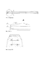
Каркас представляет собой пространственную конструкцию из четырех парных стержней, расположенных в горизонтальной плоскости и двух стержней, расположенных в вертикальной плоскости, соединенных между собой сваркой. При этом, для возможности установки каркаса на основную конструктивную арматуру расстояние между осями парных горизонтальных стержней каркаса должно быть не менее диаметра основной конструктивной стержневой арматуры, а расстояние между вертикальными стержнями каркаса должно быть не более расстояния между крайними основными конструктивными стержнями арматуры по горизонтали. Для дополнительного усиления конструкции шпалы каркас выполняется пространственной формы за счет изгиба на 90° каждого или по одному стержню из каждой пары горизонтальных стержней. Длина загибов стержней определяется технологичностью монтажа в шпальную форму.The frame is a spatial structure of four paired rods located in the horizontal plane and two rods located in the vertical plane, interconnected by welding. At the same time, in order to be able to install the frame on the main structural reinforcement, the distance between the axes of the pair of horizontal frame rods should be not less than the diameter of the main structural bar reinforcement, and the distance between the vertical frame rods should be no more than the horizontal distance between the extreme main structural reinforcement rods. To further strengthen the design of the sleepers, the frame is spatial in shape due to a 90 ° bend of each or one rod from each pair of horizontal rods. The length of the bends of the rods is determined by the manufacturability of installation in a sleeper form.
Каркасы устанавливаются в шпальную форму перед процессом формовки. Каркас фиксируется на арматурных стержнях основной конструктивной арматуры в торцевых частях формы (до заполнения формы бетонной смесью). В готовой шпале расстояние от точки выхода основной конструктивной арматуры из бетона до ближайшего стержня каркаса должно быть не менее 20 мм.Frames are installed in a sleeper form before the molding process. The frame is fixed on the reinforcing rods of the main structural reinforcement in the end parts of the mold (until the mold is filled with concrete mix). In the finished sleepers, the distance from the exit point of the main structural reinforcement from concrete to the nearest core of the frame should be at least 20 mm.
Заявленное изобретение поясняется чертежами, где на фиг. 1 схематично изображен общий вид шпалы с усилением торцевых частей дополнительным армированием каркасами; на фиг. 2 - вид А каркас, зафиксированный на арматурных стержнях, где 1 - каркас, 2 - арматурные стержни и на фиг. 3 - разрез Б-Б - общий вид расположения каркаса.The claimed invention is illustrated by drawings, where in FIG. 1 schematically shows a General view of the sleepers with reinforcement of the end parts with additional reinforcement frames; in FIG. 2 - view A of the frame fixed on reinforcing bars, where 1 is the frame, 2 is the reinforcing bars, and in FIG. 3 - section BB - a General view of the location of the frame.
Claims (3)
Priority Applications (1)
| Application Number | Priority Date | Filing Date | Title |
|---|---|---|---|
| RU2019126344A RU2716373C1 (en) | 2019-08-19 | 2019-08-19 | Method of reinforcement of end parts of reinforced concrete sleeper with additional reinforcement by frames |
Applications Claiming Priority (1)
| Application Number | Priority Date | Filing Date | Title |
|---|---|---|---|
| RU2019126344A RU2716373C1 (en) | 2019-08-19 | 2019-08-19 | Method of reinforcement of end parts of reinforced concrete sleeper with additional reinforcement by frames |
Publications (1)
| Publication Number | Publication Date |
|---|---|
| RU2716373C1 true RU2716373C1 (en) | 2020-03-11 |
Family
ID=69898695
Family Applications (1)
| Application Number | Title | Priority Date | Filing Date |
|---|---|---|---|
| RU2019126344A RU2716373C1 (en) | 2019-08-19 | 2019-08-19 | Method of reinforcement of end parts of reinforced concrete sleeper with additional reinforcement by frames |
Country Status (1)
| Country | Link |
|---|---|
| RU (1) | RU2716373C1 (en) |
Citations (5)
| Publication number | Priority date | Publication date | Assignee | Title |
|---|---|---|---|---|
| US4098460A (en) * | 1975-07-17 | 1978-07-04 | Societe Technique Pour L'utilisation De La Precontrainte | Concrete unit prestressed using tendons stressed before concreting, more particularly a railway sleeper |
| DE102005057647A1 (en) * | 2005-12-01 | 2007-06-06 | Bwg Gmbh & Co. Kg | concrete sleeper |
| CN201326141Y (en) * | 2008-11-11 | 2009-10-14 | 欧阳炎 | A dwarf sleeper capable of meeting III-type sleeper strength |
| RU109465U1 (en) * | 2011-04-27 | 2011-10-20 | Закрытое акционерное общество "РС-Комплект" | REINFORCED concrete sleepers |
| KR101780224B1 (en) * | 2015-11-09 | 2017-09-21 | 한국철도기술연구원 | Concrete long sleeper block of fast-hardening track for improving rail track considering train operation construction method |
-
2019
- 2019-08-19 RU RU2019126344A patent/RU2716373C1/en active
Patent Citations (5)
| Publication number | Priority date | Publication date | Assignee | Title |
|---|---|---|---|---|
| US4098460A (en) * | 1975-07-17 | 1978-07-04 | Societe Technique Pour L'utilisation De La Precontrainte | Concrete unit prestressed using tendons stressed before concreting, more particularly a railway sleeper |
| DE102005057647A1 (en) * | 2005-12-01 | 2007-06-06 | Bwg Gmbh & Co. Kg | concrete sleeper |
| CN201326141Y (en) * | 2008-11-11 | 2009-10-14 | 欧阳炎 | A dwarf sleeper capable of meeting III-type sleeper strength |
| RU109465U1 (en) * | 2011-04-27 | 2011-10-20 | Закрытое акционерное общество "РС-Комплект" | REINFORCED concrete sleepers |
| KR101780224B1 (en) * | 2015-11-09 | 2017-09-21 | 한국철도기술연구원 | Concrete long sleeper block of fast-hardening track for improving rail track considering train operation construction method |
Similar Documents
| Publication | Publication Date | Title |
|---|---|---|
| CN108978471B (en) | Supporting device for increasing rigidity of cable-stayed bridge special-shaped cable tower and mounting method thereof | |
| CN102864742B (en) | Anchor device of first sliding and then fixing type combined steel anchor boxes of cable stayed bridge and construction method thereof | |
| KR20010078870A (en) | Development and construction methods of the prestressed composite truss beams | |
| CN101851983A (en) | Template-free U-shaped steel concrete combination beam | |
| CN103422677A (en) | Construction method for binding steel reinforced concrete composite structure reinforcing steel bars | |
| CN113216017A (en) | Steel-encased ultrahigh-performance concrete reinforcing method for box girder | |
| CN104499608A (en) | Method for designing and constructing prestressed section steel reinforced shear wall | |
| CN207793884U (en) | The steel frame construction of Sarasota upper king-post strut | |
| RU2716373C1 (en) | Method of reinforcement of end parts of reinforced concrete sleeper with additional reinforcement by frames | |
| CN107905043B (en) | Combined rail beam system of steel web truss with suspended bottom plate opening | |
| CN103321153A (en) | Construction method for medium and small span trough girder bridge | |
| CN112761289A (en) | Local steel bar truss prestressed concrete laminated bottom plate and manufacturing method thereof | |
| CN211815595U (en) | Lower tower column tension and compression structure for cable tower | |
| CN115816639A (en) | Steel reinforcement framework suitable for railway precast beam and transverse series construction method | |
| RU196438U1 (en) | Reinforced concrete sleepers with rod reinforcement and additional reinforcement of the end part with frames | |
| CN110524675A (en) | A kind of pre-tensioning system precast H-beam and its construction method | |
| CN201722844U (en) | U-shaped steel reinforced concrete combination beam without mold plate | |
| CN109838015B (en) | High-shear-resistance concrete shear wall provided with fiber reinforced composite material grid bars | |
| CN109610349B (en) | PC box girder web plate reinforcing structure with built-in obliquely-woven mesh and method | |
| CN220619784U (en) | Prefabricated bridge plate structure for bridge | |
| KR100555253B1 (en) | The bridge construction method of having used composition double girder and this which connected and manufactured i beam by the upper and lower sides | |
| KR101023175B1 (en) | Method for manufacturing preflex composite beam and continuous composite beam using the same | |
| KR101259139B1 (en) | Steel composite prestressed concrete beam and method of manufacturing the same | |
| RU2711776C1 (en) | Method of reinforcement of end parts of reinforced concrete sleepers by additional reinforcement with spirals | |
| CN215593735U (en) | A outsourcing steel-ultra high performance concrete composite reinforcement structure for case roof beam |