RU2713503C1 - Method of angular superresolution in receiving digital antenna arrays - Google Patents
Method of angular superresolution in receiving digital antenna arrays Download PDFInfo
- Publication number
- RU2713503C1 RU2713503C1 RU2019126251A RU2019126251A RU2713503C1 RU 2713503 C1 RU2713503 C1 RU 2713503C1 RU 2019126251 A RU2019126251 A RU 2019126251A RU 2019126251 A RU2019126251 A RU 2019126251A RU 2713503 C1 RU2713503 C1 RU 2713503C1
- Authority
- RU
- Russia
- Prior art keywords
- signals
- aperture
- channels
- real
- outputs
- Prior art date
Links
- 238000000034 method Methods 0.000 title claims description 32
- 238000003491 array Methods 0.000 title claims description 9
- 238000009826 distribution Methods 0.000 claims abstract description 17
- 230000010355 oscillation Effects 0.000 claims abstract description 9
- 238000010586 diagram Methods 0.000 claims abstract description 6
- 230000005855 radiation Effects 0.000 claims description 18
- 230000003247 decreasing effect Effects 0.000 claims description 4
- 230000015572 biosynthetic process Effects 0.000 abstract description 8
- 230000000694 effects Effects 0.000 abstract 1
- 239000000126 substance Substances 0.000 abstract 1
- 230000014509 gene expression Effects 0.000 description 15
- 238000005259 measurement Methods 0.000 description 6
- 230000000737 periodic effect Effects 0.000 description 6
- 238000004971 IR microspectroscopy Methods 0.000 description 3
- 230000009471 action Effects 0.000 description 3
- 238000012060 immune response imaging Methods 0.000 description 3
- 238000005070 sampling Methods 0.000 description 3
- 238000001228 spectrum Methods 0.000 description 3
- 230000005684 electric field Effects 0.000 description 2
- 230000010287 polarization Effects 0.000 description 2
- 206010033101 Otorrhoea Diseases 0.000 description 1
- 230000003321 amplification Effects 0.000 description 1
- 230000008859 change Effects 0.000 description 1
- 238000006243 chemical reaction Methods 0.000 description 1
- 238000010835 comparative analysis Methods 0.000 description 1
- 230000001934 delay Effects 0.000 description 1
- 238000001514 detection method Methods 0.000 description 1
- 230000005672 electromagnetic field Effects 0.000 description 1
- 238000013213 extrapolation Methods 0.000 description 1
- 230000036541 health Effects 0.000 description 1
- QSHDDOUJBYECFT-UHFFFAOYSA-N mercury Chemical compound [Hg] QSHDDOUJBYECFT-UHFFFAOYSA-N 0.000 description 1
- 229910052753 mercury Inorganic materials 0.000 description 1
- 238000003199 nucleic acid amplification method Methods 0.000 description 1
- 230000003071 parasitic effect Effects 0.000 description 1
- 230000009467 reduction Effects 0.000 description 1
- 230000003595 spectral effect Effects 0.000 description 1
- 230000001629 suppression Effects 0.000 description 1
- 238000003786 synthesis reaction Methods 0.000 description 1
- 230000002123 temporal effect Effects 0.000 description 1
- 230000009466 transformation Effects 0.000 description 1
- 230000004304 visual acuity Effects 0.000 description 1
Images
Classifications
-
- G—PHYSICS
- G01—MEASURING; TESTING
- G01S—RADIO DIRECTION-FINDING; RADIO NAVIGATION; DETERMINING DISTANCE OR VELOCITY BY USE OF RADIO WAVES; LOCATING OR PRESENCE-DETECTING BY USE OF THE REFLECTION OR RERADIATION OF RADIO WAVES; ANALOGOUS ARRANGEMENTS USING OTHER WAVES
- G01S13/00—Systems using the reflection or reradiation of radio waves, e.g. radar systems; Analogous systems using reflection or reradiation of waves whose nature or wavelength is irrelevant or unspecified
- G01S13/88—Radar or analogous systems specially adapted for specific applications
- G01S13/89—Radar or analogous systems specially adapted for specific applications for mapping or imaging
- G01S13/90—Radar or analogous systems specially adapted for specific applications for mapping or imaging using synthetic aperture techniques, e.g. synthetic aperture radar [SAR] techniques
-
- H—ELECTRICITY
- H01—ELECTRIC ELEMENTS
- H01Q—ANTENNAS, i.e. RADIO AERIALS
- H01Q21/00—Antenna arrays or systems
- H01Q21/29—Combinations of different interacting antenna units for giving a desired directional characteristic
-
- H—ELECTRICITY
- H01—ELECTRIC ELEMENTS
- H01Q—ANTENNAS, i.e. RADIO AERIALS
- H01Q3/00—Arrangements for changing or varying the orientation or the shape of the directional pattern of the waves radiated from an antenna or antenna system
- H01Q3/26—Arrangements for changing or varying the orientation or the shape of the directional pattern of the waves radiated from an antenna or antenna system varying the relative phase or relative amplitude of energisation between two or more active radiating elements; varying the distribution of energy across a radiating aperture
Landscapes
- Engineering & Computer Science (AREA)
- Remote Sensing (AREA)
- Radar, Positioning & Navigation (AREA)
- Physics & Mathematics (AREA)
- Electromagnetism (AREA)
- Computer Networks & Wireless Communication (AREA)
- General Physics & Mathematics (AREA)
- Variable-Direction Aerials And Aerial Arrays (AREA)
Abstract
Description
Изобретение относится к антенной технике, а именно, к способам формирования диаграммы направленности (ДН) цифровой антенной решетки (ЦАР) и может использоваться для определения местоположения источников радиоизлучений.The invention relates to antenna technology, and in particular, to methods of forming a radiation pattern (BH) of a digital antenna array (CAR) and can be used to determine the location of radio emission sources.
Известен способ сверхразрешения сигналов по времени в активной локации [1 - Патент РФ 2658075, «Способ сверхразрешения сигналов по времени в активной локации», МПК G01S 15/00, опубл. 19.06.2018], при котором локатор дополняют блоком модификации опорного сигнала в корреляционном приемнике (технической реализации согласованного с сигналом посылки фильтра). В качестве опорного сигнала используют модифицированную в спектральной области копию посылки, то есть расширение спектра сигнала за счет частичного подавления центральной несущей частоты и управляемого усиления боковых лепестков спектра, что повышает разрешающую способность локатора инструментами сверхразрешения при цифровой обработке сигналов в активной локации, а также повышает эффективность и снижает стоимость информационно-измерительной системы местоопределения объекта.A known method of superresolution of signals in time in an active location [1 - RF Patent 2658075, “Method of superresolution of signals in time in an active location”, IPC G01S 15/00, publ. 06/19/2018], in which the locator is supplemented with a block for modifying the reference signal in the correlation receiver (technical implementation of a filter sending signal that is consistent with the signal). A copy of the package modified in the spectral region is used as a reference signal, that is, the expansion of the signal spectrum due to partial suppression of the central carrier frequency and controlled amplification of the side lobes of the spectrum, which increases the resolving power of the locator with superresolution tools when digitally processing signals in active locations, and also increases the efficiency and reduces the cost of the information-measuring system of the location of the object.
Недостатком известного способа является возможность использования сверхразрешения только в активной радиолокации при известной форме принимаемого сигнала. Для приема априорно неизвестных сигналов этот способ неприменим.The disadvantage of this method is the possibility of using superresolution only in active radar with a known form of the received signal. To receive a priori unknown signals, this method is not applicable.
Известен способ углового сверхразрешения цифровыми антенными решетками [2 - Патент РФ 2642883, «Способ углового сверхразрешения цифровыми антенными решетками», МПК H01Q 3/00, Опубл. 29.01.2018], при котором электромагнитные волны, отраженные объектами, принимают и обрабатывают в каждом из каналов реальной апертуры цифровой антенной решетки, формируют комплексные цифровые сигналы реальной апертуры. Комплексные цифровые сигналы каналов виртуальной апертуры формируют из комплексных цифровых сигналов каналов реальной апертуры путем их задержки во времени, причем задержки во времени в одноименных парциальных диаграммах направленности априорно определяют по разности хода фазового фронта волны между каналами реальной и виртуальной апертур, участвующими в формировании соответствующих сигналов каналов виртуальной апертуры. Формируют парциальные лучи многолучевой диаграммы направленности цифровой антенной решетки путем одновременного суммирования согласованных во времени комплексных цифровых сигналов каналов реальной и виртуальной апертур, которые получают из сигналов каналов реальной и виртуальной апертур путем устранения у них в одноименных парциальных лучах взаимного временного рассогласования, чем обеспечивают угловое сверхразрешение и точность измерения угловых координат, определяемые суммой реальной апертуры цифровой антенной решетки и синтезированной виртуальной.A known method of angular superresolution of digital antenna arrays [2 - RF Patent 2642883, "Method of angular superresolution of digital antenna arrays", IPC
Недостатком известного способа является формирование сигналов каналов виртуальной апертуры из сигналов каналов реальной апертуры путем их задержки во времени, при этом требуемые задержки во времени в одноименных парциальных диаграммах направленности определяют априорно. В реальных устройствах априорное определение параметров виртуальной апертуры может вносить большую погрешность в измерения, т.к. местоположение источника сигнала может измениться в процессе измерений, или параметры реальной апертуры могут отличаться от идеальных.The disadvantage of this method is the formation of signals of the channels of the virtual aperture from the signals of the channels of the real aperture by their time delay, while the required time delays in the same partial radiation patterns are determined a priori. In real devices, the a priori determination of the parameters of the virtual aperture can introduce a large error in the measurements, since the location of the signal source may change during the measurement, or the parameters of the real aperture may differ from ideal ones.
Наиболее близким по технической сущности к изобретению является способ углового сверхразрешения цифровыми антенными решетками [3 -Лаговский Б.А. Сверхразрешение на основе синтеза апертуры цифровыми антенными решетками// Антенны. 2013, №6, с. 9-16], принятый за прототип, при котором принимают электромагнитные волны от источников радиоизлучения, формируют комплексные цифровые сигналы на выходах каналов реальной апертуры, формируют сигналы на выходах каналов виртуальной апертуры из комплексных цифровых сигналов каналов реальной апертуры путем их экстраполяции с учетом координат антенных элементов реальной апертуры, формируют диаграмму направленности цифровой антенной решетки путем весового суммирования сигналов с выходов каналов реальной и синтезированной виртуальной апертур.The closest in technical essence to the invention is a method of angular superresolution of digital antenna arrays [3-Lagovsky B.A. Superresolution based on aperture synthesis by digital antenna arrays // Antennas. 2013, No.6, p. 9-16], adopted as a prototype in which electromagnetic waves from radio sources are received, complex digital signals are generated at the outputs of the channels of the real aperture, signals are generated at the outputs of the virtual aperture channels from the complex digital signals of the channels of the real aperture by extrapolation taking into account the coordinates of the antenna elements real aperture, form the radiation pattern of the digital antenna array by weighting the sum of the signals from the outputs of the channels of the real and synthesized virtual ape mercury.
Недостатком прототипа является ограничение по величине отношения сигнал-шум 12-14 дБ, при котором достигается различение угловых положений источников сигналов. В реальных условиях требуется обнаруживать сигналы с более низким отношением сигнал-шум.The disadvantage of the prototype is the restriction on the magnitude of the signal-to-noise ratio of 12-14 dB, at which a difference in the angular positions of signal sources is achieved. In real conditions, it is required to detect signals with a lower signal to noise ratio.
Технической проблемой, на решение которой направлено предлагаемое изобретение, является снижение величины отношения сигнал-шум, при котором достигается различение угловых положений источников сигналов.The technical problem to which the invention is directed is to reduce the signal-to-noise ratio, in which a difference in the angular positions of signal sources is achieved.
Для решения указанной технической проблемы предлагается способ углового сверхразрешения в приемных цифровых антенных решетках, при котором принимают электромагнитные волны от источников радиоизлучения (ИРИ), формируют квадратурные цифровые сигналы на выходах каналов реальной апертуры, формируют сигналы на выходах каналов виртуальной апертуры из квадратурных цифровых сигналов каналов реальной апертуры, формируют диаграмму направленности путем весового суммирования сигналов с выходов каналов синтезированной виртуальной апертуры.To solve this technical problem, we propose a method of angular superresolution in receiving digital antenna arrays, in which electromagnetic waves from radio sources (IRI) are received, quadrature digital signals are generated at the outputs of the channels of the real aperture, signals are generated at the outputs of the channels of the virtual aperture from quadrature digital signals of the channels of the real apertures, form a radiation pattern by weighting the sum of the signals from the outputs of the channels of the synthesized virtual aperture.
Согласно изобретению, по сигналам на выходе каналов реальной апертуры оценивают период ![]()
![]()
![]()
![]()
![]()
![]()
Техническим результатом предлагаемого способа является увеличение углового сектора, в котором выполняется различение угловых положений источников сигналов.The technical result of the proposed method is to increase the angular sector in which the angular positions of the signal sources are distinguished.
Проведенный сравнительный анализ заявленного способа и прототипа показывает, что их отличие заключается в следующем:A comparative analysis of the claimed method and prototype shows that their difference is as follows:
- в прототипе формирование сигналов на выходах каналов виртуальной апертуры выполняется путем экстраполяции сигналов каналов реальной апертуры, например, с помощью кубической интерполяции или линейного предсказания Берга. В то время как в предлагаемом способе оценивают период ![]()
![]()
![]()
![]()
![]()
![]()
Сочетание отличительных признаков и свойства предлагаемого способа из литературы не известно, поэтому он соответствует критериям новизны и изобретательского уровня.The combination of distinctive features and properties of the proposed method from the literature is not known, therefore, it meets the criteria of novelty and inventive step.
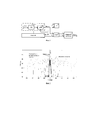
На фиг. 1 приведена структурная схема устройства, реализующего предложенный способ.In FIG. 1 shows a structural diagram of a device that implements the proposed method.
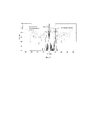
На фиг. 2 приведен сформированный предложенным способом пеленгационный рельеф при наличии трех ИРИ с отношением сигнал-шум 5 дБ.In FIG. 2 shows the direction-finding relief formed by the proposed method in the presence of three IRIs with a signal-to-noise ratio of 5 dB.
На фиг. 3 приведен сформированный предложенным способом пеленгационный рельеф при наличии трех ИРИ с угловым расстоянием между ними 20°.In FIG. 3 shows the direction-finding relief formed by the proposed method in the presence of three IRIs with an angular distance between them of 20 °.
При реализации предложенного способа выполняется следующая последовательность действий:When implementing the proposed method, the following sequence of actions is performed:
- принимают электромагнитные волны от источников радиоизлучения, формируют квадратурные цифровые сигналы на выходах каналов реальной апертуры - 1;- receive electromagnetic waves from sources of radio emission, form quadrature digital signals at the outputs of the channels of the real aperture - 1;
- по сигналам на выходе каналов реальной апертуры оценивают период ![]()
![]()
- доопределяют квадратурные составляющие сигналов на интервале, соответствующем найденному периоду ![]()
![]()
- находят коэффициенты разложения в ряд Фурье квадратурных составляющих сигналов на интервале ![]()
![]()
- определяют квадратурные составляющие сигналов на выходах каналов виртуальной апертуры путем обратного преобразования Фурье при помощи рассчитанных коэффициентов Фурье - 5;- determine the quadrature components of the signals at the outputs of the channels of the virtual aperture by the inverse Fourier transform using the calculated Fourier coefficients - 5;
- формируют сигналы на выходах каналов виртуальной апертуры из квадратурных цифровых сигналов каналов реальной апертуры - 6;- generate signals at the outputs of the channels of the virtual aperture from the quadrature digital signals of the channels of the real aperture - 6;
- формируют диаграмму направленности путем весового суммирования сигналов с выходов каналов синтезированной виртуальной апертуры - 7;- form the radiation pattern by weighting the sum of the signals from the outputs of the channels of the synthesized virtual aperture - 7;
- оценивают пеленгационный рельеф виртуальной апертуры по сформированной диаграмме направленности - 8;- evaluate the directional relief of the virtual aperture according to the formed radiation pattern - 8;
- при необходимости снижения побочных составляющих, при формировании используют весовые коэффициенты спадающего амплитудного распределения или выполняют перемножение диаграммы направленности реальной апертуры в виде весовой суммы сигналов на выходе реальной апертуры и диаграммы виртуальной апертуры, полученной путем весового суммирования сигналов с выходов каналов виртуальной апертуры - 9.- if it is necessary to reduce side components, when forming, use the weight coefficients of the falling amplitude distribution or multiply the radiation pattern of the real aperture in the form of the weighted sum of signals at the output of the real aperture and the virtual aperture diagram obtained by weighting the signals from the outputs of the channels of the virtual aperture - 9.
Вариант приемной цифровой антенной решетки (ЦАР), реализующий предложенный способ, включает в себя (фиг. 1) реальную апертуру, содержащую М приемных каналов 1, каждый из которых включает в себя последовательно соединенные антенный элемент 2, радиоприемник РП 3 и аналого-цифровой преобразователь (АЦП) 4, вход дискретизации которого соединен с одним из выходов генератора сигнала дискретизации Г 5, а выход данных соединен с одним из входов данных устройства цифровой обработки (УЦОС) 6. Выходы УЦОС 6 соединены со входами цифрового сумматора 7, выход которого является выходом устройства.An embodiment of a receiving digital antenna array (CAR) that implements the proposed method includes (Fig. 1) a real aperture containing
РП 3 для работы устройства в диапазоне метровых волн может быть выполнен в виде полосового фильтра и усилителя. В более высокочастотном диапазоне в состав РП 3 дополнительно входят смеситель и гетеродин. При этом могут быть использованы узлы, например, из [4 - стр. 142-143. Mini-Circuits. RF & Microwave components guide. 2010].
Г 5 представляет синтезатор частоты, обеспечивающий формирование сигнала дискретизации Fд. При этом может быть использован, например, синтезатор из [4 - стр. 142-143]. Сигнал синтезатора разветвляется на М выходов с помощью делителей мощности [4 - стр. 136-140].
УЦОС 6 представляет собой ЭВМ, обеспечивающую обработку отсчетов сигнала по заданному алгоритму.UTSOS 6 is a computer that provides processing of signal samples according to a given algorithm.
Цифровой сумматор 7 может быть выполнен в виде ПЛИС.The
Перед тем, как перейти к описанию работы устройства, рассмотрим теоретическое обоснование способа.Before proceeding to the description of the operation of the device, consider the theoretical justification of the method.
В соответствии с теоремой эквивалентных поверхностных токов распределение источников излучения в пространстве можно заменить распределением эквивалентных поверхностных токов вспомогательных диполей. В случае, если все источники излучения расположены в дальней зоне приемной антенны, то распределение поверхностных токов удобно задавать вдоль плоскости, которая параллельна плоскости раскрыва приемной антенны, а координаты вспомогательных диполей - при помощи направляющих косинусов.In accordance with the theorem of equivalent surface currents, the distribution of radiation sources in space can be replaced by the distribution of equivalent surface currents of auxiliary dipoles. If all radiation sources are located in the far zone of the receiving antenna, then it is convenient to set the distribution of surface currents along a plane that is parallel to the opening plane of the receiving antenna, and the coordinates of the auxiliary dipoles using guide cosines.
Рассмотрим в качестве приемной антенны М-элементную линейную эквидистантную ЦАР линейной поляризации. Координаты фазовых центров приемных антенных элементов обозначим хm (m=1, 2, …, М). Будем считать,Consider the M-element linear equidistant CAR of linear polarization as the receiving antenna. The coordinates of the phase centers of the receiving antenna elements are denoted by x m (m = 1, 2, ..., M). We assume,
что длина ЦАР равна Lx и хm∈[-Lx /2, Lx/2]. В дальней зоне ЦАР расположена плоскость, вдоль которой задано распределение эквивалентных электрических поверхностных токов J(u) (считаем, что составляющие магнитных поверхностных токов равны нулю).that the CAR length is L x and x m ∈ [-L x / 2, L x / 2]. In the far zone of the Central African Republic, there is a plane along which the distribution of equivalent electric surface currents J (u) is given (we assume that the components of the magnetic surface currents are zero).
Распределение напряженности электрического поля вдоль оси 0х, создаваемого вспомогательными диполями той же поляризации, что и приемная ЦАР, описывает интегралThe distribution of the electric field along the axis 0x, created by auxiliary dipoles of the same polarization as the receiving CAR, describes the integral
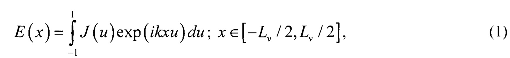
где Lν - размеры виртуального раскрыва;where L ν - dimensions of the virtual aperture;
u=sinθ - координата точки наблюдения;u = sinθ is the coordinate of the observation point;
ηm - шум m -го канала;η m is the noise of the mth channel;
k=2π/λ - волновое число;k = 2π / λ is the wave number;
λ -длина волны;λ is the wavelength;
θ - угловая координата.θ is the angular coordinate.
Пусть в точках с координатами un (n=1, 2, …, N) размещены ИРИ с комплексными амплитудами Jn=|Jn|exp(iψn), а остальным точкам пространства соответствует белый шум, огибающую которого определяет комплексная функция n(u) с дисперсией σ2. В этом случае функцию J (u) можно представить в виде:Let IRI with complex amplitudes J n = | J n | exp (iψ n ) be placed at points with coordinates u n (n = 1, 2, ..., N), and the other white space points correspond to white noise whose envelope is determined by the complex function n (u) with a variance of σ 2 . In this case, the function J (u) can be represented as:
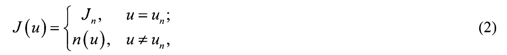
Подставим выражение (2) в формулу (1), тогда получим распределение комплексных амплитуд сигналов на выходе m-го канала для модели воздействия системы дискретных источниковWe substitute expression (2) into formula (1), then we obtain the distribution of the complex amplitudes of the signals at the output of the mth channel for the model of the action of the system of discrete sources

В выражении (3) оба слагаемых представляют собой суммы периодических функций.In expression (3), both terms are sums of periodic functions.
Известно, что сумма периодических функций также является периодической функцией. Ее период представляет собой наименьшее общее кратное (НОК) периодов всех составляющих суммы. Очевидно, что во второе слагаемое входит очень большое число слагаемых с различными периодами. Это приводит к тому, что период второго слагаемого в общем случае представляет собой очень большое число. Первое слагаемое в выражении (3) содержит ограниченное число членов ряда. Это позволяет рассматривать его как периодическую функциюIt is known that the sum of periodic functions is also a periodic function. Its period is the smallest total multiple (LCL) of the periods of all the components of the amount. Obviously, the second term includes a very large number of terms with different periods. This leads to the fact that the period of the second term in the general case is a very large number. The first term in expression (3) contains a limited number of members of the series. This allows us to consider it as a periodic function
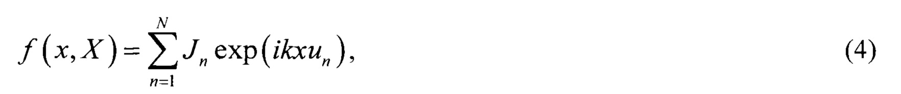
где X - период или НОК периодов отдельных колебаний, равных Х'n=λ/un.where X is the period or NOC of the periods of individual oscillations equal to X ' n = λ / u n .
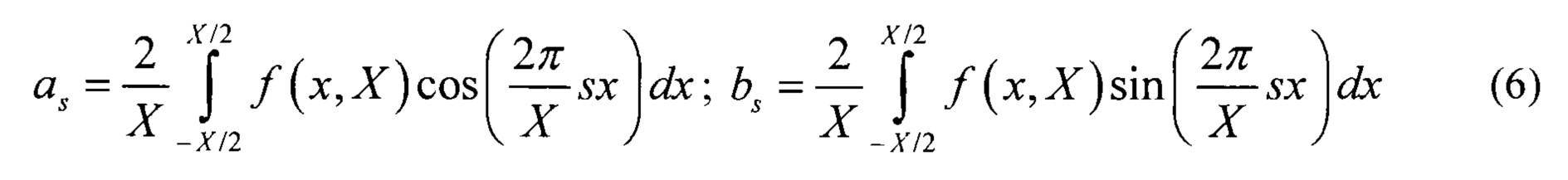
Если период X известен, то функцию ƒ=(х, Х) можно представить в виде ряда ФурьеIf the period X is known, then the function ƒ = (x, X) can be represented as a Fourier series

с комплексными коэффициентамиwith complex coefficients
Для некоторой гармоники с номером s с существенной амплитудой должно выполняться равенствоFor some harmonic with number s with significant amplitude, the equality

Отсюда следует, что выражение (4) может быть представлено в виде ряда Фурье, в котором номера ненулевых гармоник однозначным образом связаны с координатами ИРИ.It follows that expression (4) can be represented as a Fourier series in which the numbers of nonzero harmonics are uniquely related to the coordinates of the IRI.
Теоретически возможно такое расположение ИРИ, при котором НОК X совпадает с периодом члена ряда (5) с наибольшим периодом, который обозначим ![]()
![]()

точно совпадут.exactly match.
Если период ![]()
![]()
Приведенные рассуждения показывают, что в ряде случаев для оценки координат ИРИ достаточно оценить наибольший период ![]()
![]()
Однако для формирования распределения поля в виртуальной апертуре в виде ряда (8) необходимо сначала найти параметр ![]()
![]()
Комплексные амплитуды сигналов на выходе m-го канала ЦАР с точностью до постоянного множителя соответствуют распределению комплексных амплитуд напряженности электрического поля на участке виртуального раскрыва, т.е.The complex amplitudes of the signals at the output of the m-th channel of the CAR up to a constant factor correspond to the distribution of the complex amplitudes of the electric field strength in the section of the virtual aperture, i.e.
![]()
![]()
где ηm - внутренний шум m -го канала.where η m is the internal noise of the mth channel.
Принимаемые комплексные амплитуды сигналов ЦАР Аm могут быть разделены на две квадратурные составляющие Re(Аm) и Im(Аm). Эти квадратурные составляющие представляют собой периодические функции с одинаковым периодом, который может быть оценен по одной из формул:The received complex amplitudes of the CAR signals A m can be divided into two quadrature components Re (A m ) and Im (A m ). These quadrature components are periodic functions with the same period, which can be estimated using one of the formulas:

илиor
![]()
![]()
Выбор формулы (12) или (13) обусловлен тем, в какой из квадратурных составляющих достигнуто наибольшее значение периода. В ряде случаев может оказаться так, что в пределах раскрыва ЦАР укладывается несколько периодов низкочастотных колебаний.The choice of formula (12) or (13) is due to the fact in which of the quadrature components the greatest value of the period is achieved. In some cases, it may turn out that several periods of low-frequency oscillations fit within the CAR opening.
Для того, чтобы найти спектр функции ƒ(х, Х) в виде ряда (8), необходимо по имеющимся измерениям квадратурных составляющих Re(Am) и Im(Am) доопределить функцию ƒ(x, X) на интервале, соответствующем периоду ![]()
![]()
Если параметр ![]()
![]()
![]()
![]()
![]()
![]()
![]()
![]()
Если параметр ![]()
![]()
![]()
![]()
![]()
![]()
![]()
![]()
Выражения (14)-(17) выражают принцип доопределения квадратурных составляющих до интервала ![]()
![]()
В результате применения выражений (14)-(17) формируется набор узловых значений функции ƒ(xn, X) в точках ![]()
![]()
Выражения (14)-(17) показывают ограничения реальной ЦАР при определении периода ![]()
![]()
![]()
![]()
![]()
![]()
После доопределения узловых точек ![]()
![]()

и найдены соответствующие коэффициенты разложения В1 и В2 в ряд по базисным функциям.and the corresponding expansion coefficients of B 1 and B 2 in a series of basis functions are found.
Для найденных коэффициентов разложения периодической функции несложно сформировать распределение комплексных амплитуд вдоль виртуальной апертуры в виде рядаFor the found expansion coefficients of the periodic function, it is easy to formulate the distribution of complex amplitudes along the virtual aperture in the form of a series
![]()
![]()
где х'm'∈[-Lν /2, Lν/2].и m'=1, 2, …, М'; М' - число элементов виртуальной апертуры.where x 'm' ∈ [-L ν / 2, L ν /2].i m '= 1, 2, ..., M; M 'is the number of elements of the virtual aperture.
Следует отметить, что число S членов ряда в выражении (19) влияет на высокочастотные составляющие колебания (19). С одной стороны, высокочастотные составляющие могут быть обусловлены воздействием внутренних шумов. С другой стороны, высокочастотные составляющие обусловлены влиянием ИРИ, координаты которых удалены от направления нормали к раскрыву. В связи с этим, ограничение числа членов ряда (19) приводит как к ослаблению шумов, но также может привести к ограничению пространственной области, в которой возможно обнаружение ИРИ.It should be noted that the number S of members of the series in expression (19) affects the high-frequency components of the vibration (19). On the one hand, high-frequency components may be due to internal noise. On the other hand, the high-frequency components are caused by the influence of IRI, the coordinates of which are remote from the direction of the normal to the opening. In this regard, limiting the number of terms in series (19) leads to both attenuation of noise, but can also lead to a limitation of the spatial region in which IRI detection is possible.
После формирования функции ƒ(x', X)вдоль виртуального раскрыва в виде ряда (19) может быть построен пеленгационный рельеф виртуальной апертуры по формулеAfter the formation of the function ƒ (x ', X) along the virtual aperture in the form of series (19), the direction-finding relief of the virtual aperture can be constructed according to the formula
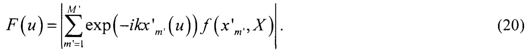
При построении пеленгационного рельефа виртуальной апертуры может потребоваться уменьшение боковых лепестков, обусловленных погрешностями полученных оценок и шумами измерений. Для этого можно ввестиWhen constructing a directional relief of a virtual aperture, it may be necessary to reduce the side lobes due to errors in the obtained estimates and measurement noise. You can enter
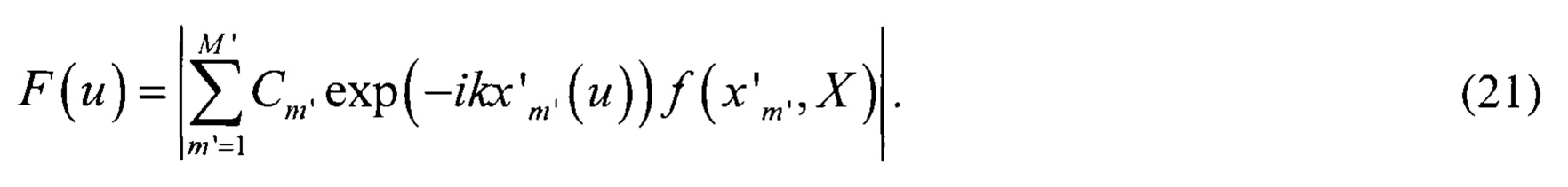
дополнительные весовые коэффициенты С=(Сm'), характеризующие весовые коэффициенты в виртуальном раскрыве. В качестве соответствующих коэффициентов можно использовать известные в теории антенных решеток спадающие амплитудные распределения Чебышева, Ханна и т.д.additional weights C = (C m ' ), characterizing the weights in the virtual aperture. As the corresponding coefficients, the decreasing amplitude distributions of Chebyshev, Hann, etc., known in the theory of antenna arrays, can be used.
В этом случае пеленгационный рельеф можно представить в видеIn this case, the bearing relief can be represented as
Кроме того, для устранения паразитных лепестков пеленгационного рельефа можно использовать нелинейное преобразование, учитывающее ДН ЦАР. При этом пеленгационный рельеф может быть получен по формуле:In addition, to eliminate the parasitic petals of the directional relief, you can use the nonlinear transformation, taking into account the CAR day. In this direction finding relief can be obtained by the formula:
Таким образом, для реализации предлагаемого способа углового сверхразрешения в приемных ЦАР выполняют следующие действия, реализуемые в устройстве на фиг. 1.Thus, in order to implement the proposed method of angular superresolution in the receiving CARs, the following actions are implemented in the device of FIG. 1.
АЭ 2 каждого приемного канала 1 преобразует энергию электромагнитного поля в энергию токов высокой частоты, поступающих на вход соответствующего РП 3, где осуществляется усиление принятого сигнала, и, при необходимости, преобразование частоты и демодуляция. Выходной сигнал РП 3 каждого канала ЦАР поступает на вход соответствующего АЦП 4, на выходе которого формируется последовательность дискретных отсчетов составляющих сигналов с шагом, задаваемым Г 5.AE 2 of each receiving
Полученные отсчеты поступают на вход УЦОС 6, в котором выполняют оценку комплексных амплитуд сигналов всех каналов ЦАР, формируют квадратурные цифровые сигналы на выходах каналов реальной апертуры ЦАР, оценивают период ![]()
![]()
![]()
![]()
![]()
![]()
Формируют диаграмму направленности путем весового суммирования сигналов с выходов каналов синтезированной виртуальной апертуры в цифровом сумматоре 7 по выражению (20). После этого оценивают пеленгационный рельеф виртуальной апертуры по сформированной диаграмме направленности.A radiation pattern is formed by weighting the sum of the signals from the outputs of the channels of the synthesized virtual aperture in a
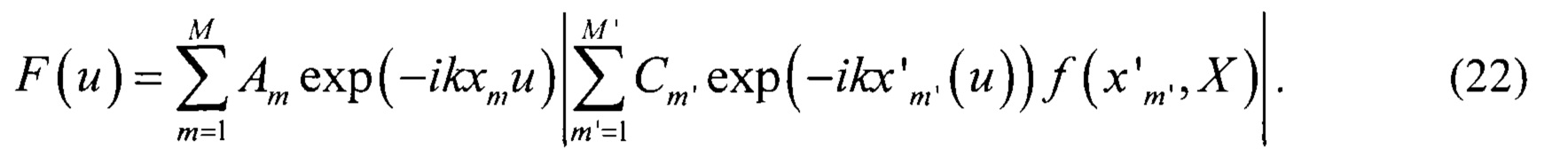
При необходимости снижения побочных составляющих, при формировании используют весовые коэффициенты спадающего амплитудного распределения по выражению (21) или выполняют перемножение диаграммы направленности реальной апертуры в виде весовой суммы сигналов на выходе реальной апертуры и диаграммы виртуальной апертуры, полученной путем весового суммирования сигналов с выходов каналов виртуальной апертуры по выражению (22).If it is necessary to reduce side components, the formation uses weighting coefficients of the decreasing amplitude distribution according to expression (21) or multiplying the radiation pattern of the real aperture in the form of the weighted sum of signals at the output of the real aperture and the virtual aperture diagram obtained by weighting the signals from the outputs of the channels of the virtual aperture by the expression (22).
Проверка работоспособности предложенного способа выполнена путем математического моделирования.The health check of the proposed method is performed by mathematical modeling.
Пример результатов моделирования работы устройства, реализующего способ, при размерах виртуальной апертуры, превышающих размеры реальной апертуры ЦАР в семь раз для трех ИРИ, с координатами 0°, ±2°, приведен на фиг. 2. Величина отношения сигнал-шум составляет 5 дБ. Ошибка измерения азимута не превышает 0,2°An example of the results of modeling the operation of a device that implements the method, with virtual aperture sizes seven times larger than the real CAR aperture for three IRIs, with
Таким образом, предложенный способ обеспечивает работу при отношении сигнал-шум, значительно более низком, чем в прототипе, для которого требуется отношение сигнал-шум не ниже 12-14 дБ.Thus, the proposed method provides operation at a signal-to-noise ratio significantly lower than in the prototype, which requires a signal-to-noise ratio of at least 12-14 dB.
На фиг 3 приведен результат моделирования работы устройства по предложенному способу для ИРИ при ориентации одного из ИРИ в направлении 20° относительно нормали раскрыва. В прототипе приведены примеры углового сверхразрешения в пределах углового сектора, не превышающем ±2,5° [3 - рис. 2, 4, 6]Figure 3 shows the result of modeling the operation of the device according to the proposed method for IRI with the orientation of one of the IRI in the direction of 20 ° relative to the normal of the aperture. The prototype provides examples of angular superresolution within the angular sector, not exceeding ± 2.5 ° [3 - Fig. 2, 4, 6]
Таким образом, предложенный способ, по сравнению с прототипом, обеспечивает увеличение углового сектора, в котором выполняется различение угловых положений источников сигналов в восемь раз.Thus, the proposed method, in comparison with the prototype, provides an increase in the angular sector in which the angular position of the signal sources is distinguished by eight times.
Приведенные выше материалы о возможной реализации способа на основе известных блоков и устройств подтверждают соответствие критерию "промышленная применимость" предложенного способа.The above materials on the possible implementation of the method based on known blocks and devices confirm compliance with the criterion of "industrial applicability" of the proposed method.
Таким образом, предлагаемый способ сверхразрешения в цифровых антенных решетках практически реализуем и обеспечивает снижение величины отношения сигнал-шум, при котором достигается различение угловых положений источников сигналов.Thus, the proposed method of superresolution in digital antenna arrays is practically feasible and provides a reduction in the signal-to-noise ratio, at which a difference in the angular positions of signal sources is achieved.
Кроме того, предложенный способ, по сравнению с прототипом, обеспечивает увеличение углового сектора, в котором выполняется различение угловых положений источников сигналов, в восемь раз.In addition, the proposed method, in comparison with the prototype, provides an increase in the angular sector in which the angular positions of the signal sources are distinguished by eight times.
Claims (1)
Priority Applications (1)
| Application Number | Priority Date | Filing Date | Title |
|---|---|---|---|
| RU2019126251A RU2713503C1 (en) | 2019-08-19 | 2019-08-19 | Method of angular superresolution in receiving digital antenna arrays |
Applications Claiming Priority (1)
| Application Number | Priority Date | Filing Date | Title |
|---|---|---|---|
| RU2019126251A RU2713503C1 (en) | 2019-08-19 | 2019-08-19 | Method of angular superresolution in receiving digital antenna arrays |
Publications (1)
| Publication Number | Publication Date |
|---|---|
| RU2713503C1 true RU2713503C1 (en) | 2020-02-05 |
Family
ID=69624886
Family Applications (1)
| Application Number | Title | Priority Date | Filing Date |
|---|---|---|---|
| RU2019126251A RU2713503C1 (en) | 2019-08-19 | 2019-08-19 | Method of angular superresolution in receiving digital antenna arrays |
Country Status (1)
| Country | Link |
|---|---|
| RU (1) | RU2713503C1 (en) |
Cited By (2)
| Publication number | Priority date | Publication date | Assignee | Title |
|---|---|---|---|---|
| RU2746063C1 (en) * | 2020-07-21 | 2021-04-06 | Федеральное государственное унитарное предприятие "Ростовский-на-Дону научно-исследовательский институт радиосвязи" (ФГУП "РНИИРС") | The method of angular superresolution in the receiving digital antenna array |
| CN114384516A (en) * | 2022-01-12 | 2022-04-22 | 电子科技大学 | A real-time angular super-resolution method for real-aperture radar based on detection before reconstruction |
Citations (4)
| Publication number | Priority date | Publication date | Assignee | Title |
|---|---|---|---|---|
| JP2003090880A (en) * | 2001-09-19 | 2003-03-28 | Mitsubishi Electric Corp | Synthetic aperture radar apparatus and image reproducing method in synthetic aperture radar apparatus |
| RU2265866C1 (en) * | 2004-01-28 | 2005-12-10 | Закрытое акционерное общество "Новые технологии" | Method for increasing radiolocation resolution, system for realization of method and method for remote detection of small objects by system |
| CN107064904A (en) * | 2017-06-08 | 2017-08-18 | 哈尔滨工业大学 | A kind of carrier-borne high-frequency ground wave radar orientation High Resolution Method based on virtual aperture |
| RU2642883C1 (en) * | 2017-01-31 | 2018-01-29 | Акционерное общество "Всероссийский научно-исследовательский институт радиотехники" | Method of angular superresolution by digital antenna arrays |
-
2019
- 2019-08-19 RU RU2019126251A patent/RU2713503C1/en active
Patent Citations (4)
| Publication number | Priority date | Publication date | Assignee | Title |
|---|---|---|---|---|
| JP2003090880A (en) * | 2001-09-19 | 2003-03-28 | Mitsubishi Electric Corp | Synthetic aperture radar apparatus and image reproducing method in synthetic aperture radar apparatus |
| RU2265866C1 (en) * | 2004-01-28 | 2005-12-10 | Закрытое акционерное общество "Новые технологии" | Method for increasing radiolocation resolution, system for realization of method and method for remote detection of small objects by system |
| RU2642883C1 (en) * | 2017-01-31 | 2018-01-29 | Акционерное общество "Всероссийский научно-исследовательский институт радиотехники" | Method of angular superresolution by digital antenna arrays |
| CN107064904A (en) * | 2017-06-08 | 2017-08-18 | 哈尔滨工业大学 | A kind of carrier-borne high-frequency ground wave radar orientation High Resolution Method based on virtual aperture |
Non-Patent Citations (4)
| Title |
|---|
| Wen Jiang et al, Radar angular superresolution algorithm based on Fourier-Wavelet regularized deconvolution, 2013 IEEE International Geoscience and Remote Sensing Symposium (IGARSS), 21-26 July 2013. * |
| Пархоменко Н.Г., Повышение вычислительной эффективности поляризационно-независимых методов углового сверхразрешения, Электротехнические и информационные комплексы и системы N4, 2010 * |
| Пархоменко Н.Г., Повышение вычислительной эффективности поляризационно-независимых методов углового сверхразрешения, Электротехнические и информационные комплексы и системы N4, 2010. Ратынский М.В., Адаптация и сверхразрешение в антенных решетках, Радио и связь, Москва, 2003. Wen Jiang et al, Radar angular superresolution algorithm based on Fourier-Wavelet regularized deconvolution, 2013 IEEE International Geoscience and Remote Sensing Symposium (IGARSS), 21-26 July 2013. RU 2642883 C1 - 2018-01-29. RU 2265866 C1 - 2005-12-10. JP 2003090880 A - 2003-03-28. CN 107064904 A - 2017-08-18. * |
| Ратынский М.В., Адаптация и сверхразрешение в антенных решетках, Радио и связь, Москва, 2003. * |
Cited By (2)
| Publication number | Priority date | Publication date | Assignee | Title |
|---|---|---|---|---|
| RU2746063C1 (en) * | 2020-07-21 | 2021-04-06 | Федеральное государственное унитарное предприятие "Ростовский-на-Дону научно-исследовательский институт радиосвязи" (ФГУП "РНИИРС") | The method of angular superresolution in the receiving digital antenna array |
| CN114384516A (en) * | 2022-01-12 | 2022-04-22 | 电子科技大学 | A real-time angular super-resolution method for real-aperture radar based on detection before reconstruction |
Similar Documents
| Publication | Publication Date | Title |
|---|---|---|
| CN107037396B (en) | Angle of arrival estimation | |
| Talisa et al. | Benefits of digital phased array radars | |
| US10145936B2 (en) | Radar device | |
| CN106546983B (en) | Radar apparatus | |
| EP2662699A1 (en) | Detection and ranging apparatus and ranging method | |
| CN111273267B (en) | Signal processing method, system and device based on phased array incoherent scattering radar | |
| RU2495447C2 (en) | Beam forming method | |
| Gupta et al. | Comparison of conventional and subspace based algorithms to estimate Direction of Arrival (DOA) | |
| RU2515179C1 (en) | Method of determining direction of hydroacoustic transponder in multibeam navigation signal propagation conditions | |
| RU2713503C1 (en) | Method of angular superresolution in receiving digital antenna arrays | |
| JP2010078420A (en) | Electric wave direction detecting apparatus and beam forming apparatus | |
| RU2491569C2 (en) | Method of direction finding with increased resolution ability | |
| RU2407026C1 (en) | Location finding method of narrow-band radio signals of short-wave range | |
| CN114879135A (en) | Coherent signal direction of arrival estimation method based on 1bit coding super surface | |
| RU2614035C1 (en) | One-stage method of decameter range radiation sources direction finding using phased antenna array consisting of mutually orthogonal symmetric horizontal dipoles | |
| RU2746063C1 (en) | The method of angular superresolution in the receiving digital antenna array | |
| JP2021143854A (en) | Device and method for estimating angle of object position and radar device | |
| RU2471200C1 (en) | Method for passive detection and spatial localisation of mobile objects | |
| RU2521959C1 (en) | Amplitude-based method for radio direction-finding and radio direction-finder for implementation thereof | |
| Cui et al. | Research on Direction Finding Technology Combining Interferometer and Spectral Estimation | |
| Pulipati et al. | A 16-element 2.4-GHz digital array receiver using 2-D IIR spatially-bandpass plane-wave filter | |
| Al-Azzo et al. | Comparison between classical and modern methods of direction of arrival (DOA) estimation | |
| Kirschner et al. | MIMO radar setups by nesting braced minimum redundancy arrays | |
| Belyaev et al. | The range of pedestrian detection with automotive radar | |
| Awwad et al. | Modeling and Optimization of a Range-Selective Digital Array Radar |