RU2704731C2 - Multi-axis joint hinge cover - Google Patents
Multi-axis joint hinge cover Download PDFInfo
- Publication number
- RU2704731C2 RU2704731C2 RU2017122980A RU2017122980A RU2704731C2 RU 2704731 C2 RU2704731 C2 RU 2704731C2 RU 2017122980 A RU2017122980 A RU 2017122980A RU 2017122980 A RU2017122980 A RU 2017122980A RU 2704731 C2 RU2704731 C2 RU 2704731C2
- Authority
- RU
- Russia
- Prior art keywords
- hinge
- axis hinge
- axis
- computing device
- flexible cover
- Prior art date
Links
Images


Classifications
-
- G—PHYSICS
- G06—COMPUTING; CALCULATING OR COUNTING
- G06F—ELECTRIC DIGITAL DATA PROCESSING
- G06F1/00—Details not covered by groups G06F3/00 - G06F13/00 and G06F21/00
- G06F1/16—Constructional details or arrangements
- G06F1/1613—Constructional details or arrangements for portable computers
- G06F1/1633—Constructional details or arrangements of portable computers not specific to the type of enclosures covered by groups G06F1/1615 - G06F1/1626
- G06F1/1675—Miscellaneous details related to the relative movement between the different enclosures or enclosure parts
- G06F1/1681—Details related solely to hinges
-
- G—PHYSICS
- G06—COMPUTING; CALCULATING OR COUNTING
- G06F—ELECTRIC DIGITAL DATA PROCESSING
- G06F1/00—Details not covered by groups G06F3/00 - G06F13/00 and G06F21/00
- G06F1/16—Constructional details or arrangements
- G06F1/1613—Constructional details or arrangements for portable computers
- G06F1/1615—Constructional details or arrangements for portable computers with several enclosures having relative motions, each enclosure supporting at least one I/O or computing function
- G06F1/1616—Constructional details or arrangements for portable computers with several enclosures having relative motions, each enclosure supporting at least one I/O or computing function with folding flat displays, e.g. laptop computers or notebooks having a clamshell configuration, with body parts pivoting to an open position around an axis parallel to the plane they define in closed position
-
- G—PHYSICS
- G06—COMPUTING; CALCULATING OR COUNTING
- G06F—ELECTRIC DIGITAL DATA PROCESSING
- G06F1/00—Details not covered by groups G06F3/00 - G06F13/00 and G06F21/00
- G06F1/16—Constructional details or arrangements
- G06F1/1613—Constructional details or arrangements for portable computers
- G06F1/163—Wearable computers, e.g. on a belt
-
- G—PHYSICS
- G06—COMPUTING; CALCULATING OR COUNTING
- G06F—ELECTRIC DIGITAL DATA PROCESSING
- G06F1/00—Details not covered by groups G06F3/00 - G06F13/00 and G06F21/00
- G06F1/16—Constructional details or arrangements
- G06F1/1613—Constructional details or arrangements for portable computers
- G06F1/1633—Constructional details or arrangements of portable computers not specific to the type of enclosures covered by groups G06F1/1615 - G06F1/1626
- G06F1/1637—Details related to the display arrangement, including those related to the mounting of the display in the housing
- G06F1/1652—Details related to the display arrangement, including those related to the mounting of the display in the housing the display being flexible, e.g. mimicking a sheet of paper, or rollable
-
- H—ELECTRICITY
- H04—ELECTRIC COMMUNICATION TECHNIQUE
- H04M—TELEPHONIC COMMUNICATION
- H04M1/00—Substation equipment, e.g. for use by subscribers
- H04M1/02—Constructional features of telephone sets
- H04M1/0202—Portable telephone sets, e.g. cordless phones, mobile phones or bar type handsets
- H04M1/0206—Portable telephones comprising a plurality of mechanically joined movable body parts, e.g. hinged housings
- H04M1/0208—Portable telephones comprising a plurality of mechanically joined movable body parts, e.g. hinged housings characterized by the relative motions of the body parts
- H04M1/0214—Foldable telephones, i.e. with body parts pivoting to an open position around an axis parallel to the plane they define in closed position
- H04M1/0216—Foldable in one direction, i.e. using a one degree of freedom hinge
- H04M1/022—The hinge comprising two parallel pivoting axes
Landscapes
- Engineering & Computer Science (AREA)
- Theoretical Computer Science (AREA)
- Computer Hardware Design (AREA)
- Physics & Mathematics (AREA)
- General Physics & Mathematics (AREA)
- General Engineering & Computer Science (AREA)
- Human Computer Interaction (AREA)
- Signal Processing (AREA)
- Mathematical Physics (AREA)
- Casings For Electric Apparatus (AREA)
- Pivots And Pivotal Connections (AREA)
- Telephone Set Structure (AREA)
- Hinges (AREA)
- Purses, Travelling Bags, Baskets, Or Suitcases (AREA)
Abstract
Description
КРАТКОЕ ОПИСАНИЕ ЧЕРТЕЖЕЙBRIEF DESCRIPTION OF THE DRAWINGS
Прилагаемые чертежи иллюстрируют воплощения концепций, о которых идет речь в данном документе. Признаки иллюстрируемых воплощений можно будет легче понять, обратившись к нижеследующему описанию, приводимому в связи с прилагаемыми чертежами. Одинаковые позиции на различных чертежах всюду используются для обозначения одинаковых элементов. Кроме того, крайняя слева цифра каждой позиции обозначает чертеж и связана с рассуждениями, где эта позиция впервые вводится.The accompanying drawings illustrate embodiments of the concepts discussed herein. The features of the illustrated embodiments will be easier to understand by referring to the following description given in connection with the accompanying drawings. The same reference numbers throughout the various drawings are used throughout to refer to like elements. In addition, the leftmost digit of each item denotes a drawing and is associated with reasoning where this item is first introduced.
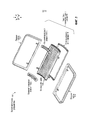
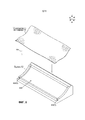
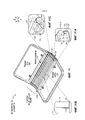
На фиг.1 показан вид в перспективе возможного устройства, которое включает в себя пример узла с гибкой крышкой многоосного шарнира в соответствии с некоторыми воплощениями предлагаемых концепций.Figure 1 shows a perspective view of a possible device, which includes an example of a node with a flexible cover multi-axis hinge in accordance with some embodiments of the proposed concepts.
На фиг.2 показан вид в перспективе в разобранном виде возможного устройства согласно фиг.1.FIG. 2 shows an exploded perspective view of a possible device according to FIG. 1.
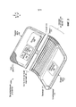
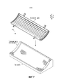
На фиг.3 показан вид в перспективе еще одного возможного устройства, которое включает в себя пример узла с гибкой крышкой многоосного шарнира в соответствии с некоторыми воплощениями предлагаемых концепций.Figure 3 shows a perspective view of another possible device, which includes an example of a node with a flexible cover multi-axis hinge in accordance with some embodiments of the proposed concepts.
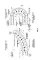
На фиг.4 показаны виды сбоку еще одного возможного устройства, которое аналогично устройству согласно фиг.1.Figure 4 shows side views of another possible device, which is similar to the device according to figure 1.
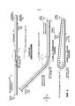
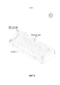
На фиг.5 показаны виды сбоку еще одного возможного устройства, которое включает в себя пример узла с гибкой крышкой многоосного шарнира в соответствии с некоторыми воплощениями предлагаемых концепций.Figure 5 shows side views of another possible device, which includes an example of a node with a flexible cover multi-axis hinge in accordance with some embodiments of the proposed concepts.
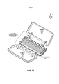
На фиг.6-11C показан пример процесса сборки возможного устройства согласно фиг.1 в соответствии с некоторыми воплощениями предлагаемых концепций.Figures 6-11C show an example of the assembly process of a possible device according to figure 1 in accordance with some embodiments of the proposed concepts.
ПОДРОБНОЕ ОПИСАНИЕ ИЗОБРЕТЕНИЯDETAILED DESCRIPTION OF THE INVENTION
Предлагаемые концепции относятся к гибким многоосным шарнирным крышкам для шарниров с многочисленными осями или многоосных шарниров. В вычислительных устройствах возможно применение многоосных шарниров для крепления с возможностью поворота частей вычислительного устройства. Предлагаемые концепции могут предусматривать гибкие крыши многоосных шарниров, располагаемые поверх многоосных шарниров, для защиты этих шарниров от посторонних предметов и/или защиты пользователя вычислительного устройства от защемления многоосными шарнирами во время поворота.The proposed concepts relate to flexible multi-axis hinge covers for multi-axis hinges or multi-axis hinges. In computing devices, it is possible to use multi-axis hinges for fastening with the possibility of rotation of parts of the computing device. Proposed concepts may include flexible roofs of multi-axle hinges located on top of multi-axis hinges to protect these hinges from foreign objects and / or to protect the user of the computing device from being pinched by multi-axis hinges during rotation.
Вводные фиг.1 и 2 вместе иллюстрируют пример вычислительного устройства 100. На фиг.2 представлено изображение в разобранном виде вычислительного устройства под таким же углом зрения, как на фиг.1. В этом примере вычислительное устройство 100 имеет первую и вторую части 102 и 104, которые скреплены с возможностью поворота посредством многоосного шарнира 106. Гибкая крышка 108 многоосного шарнира может проходить от первой части 102 до второй части 104, накрывая многоосный шарнир 106.The introductory figures 1 and 2 together illustrate an example of a computing device 100. FIG. 2 shows an exploded view of a computing device from the same angle of view as in FIG. In this example, the computing device 100 has first and
В этом случае, гибкая крышка 108 многоосного шарнира накрывает «тыльную» или «наружную» (например, обращенную от читателя) поверхность вычислительного устройства 100. В других случаях, гибкая крышка 108 многоосного шарнира может накрывать внутреннюю поверхность, либо как внутреннюю, так и наружную поверхности. В этом воплощении, гибкую крышку 108 многоосного шарнира можно крепить к многоосному шарниру 106 посредством противоположных концевых крепежных элементов 110(1) и 110(2). В этом случае, концевые крепежные элементы 110 могут имитировать профиль многоосного шарнира 106, являющийся в целом непрерывным по ширине компьютера (например, в направлении координатной оси y). Многоосный шарнир 106, гибкая крышка 108 многоосного шарнира и/или крепежные элементы, такие, как концевые крепежные элементы 110, можно считать узлом 112 гибкой крышки многоосного шарнира.In this case, the
В различных конфигурациях, как показано на фиг.1, вычислительное устройство 100 также может включать в себя элемент или устройство 114 ввода. В этом случае устройство 114 ввода реализовано в виде клавиатуры 116. В других воплощениях возможно применение других устройств ввода. В этом примере, вычислительное устройство также может включать в себя - среди прочих компонентов - экран 118 дисплея, такой, как экран чувствительного к прикосновению дисплея. Вычислительное устройство также может включать в себя процессор 120, запоминающее устройство 122, батарею 124 и/или графический процессор 126. Эти элементы могут быть расположены в первой части 102 и/или второй части 104. (Компоненты 114-126 не показаны на фиг.2).In various configurations, as shown in FIG. 1, computing device 100 may also include an input element or
Узел 112 гибкой крышки многоосного шарнира может быть прикреплен к первой и второй частям 102 и 104 с возможностью поворота между ними. Узел 112 гибкой крышки многоосного шарнира может быть прикреплен к первой и второй частям относительно постоянным образом (например, таким образом, что конечный потребитель не сможет легко разъединить это крепление) - так, как изображено на фиг.1-2. В альтернативном варианте, узел 112 гибкой крышки многоосного шарнира может быть прикреплен к первой и второй частям с возможностью относительно быстрого крепления и открепления (например, таким образом, что конечный потребитель сможет легко разъединить это крепление). Один такой пример этой последней конфигурации показан на фиг.3.The flexible cover assembly 112 of the multi-axis joint can be attached to the first and
На фиг.3 показан вид, аналогичный виду согласно фиг.1. В этом случае, вычислительное устройство 100A включает в себя первую и вторую части 102 и 104, которые скреплены с возможностью поворота узлом 112A гибкой крышки многоосного шарнира. В этом примере, конфигурация узла 112A гибкой крышки многоосного шарнира предоставляет конечному потребителю возможность легкого отсоединения любой из первой и второй частей 102 и 104 либо их обоих от узла 112A гибкой крышки многоосного шарнира, что обозначено стрелкой 302. В этом примере узел 112A гибкой крышки многоосного шарнира может включать в себя узел 304 быстрого крепления-открепления. Узел 304 быстрого крепления-открепления может включать в себя совместно работающие элементы или элементы 306 и 308 сопряжения, находящиеся на первой части 102 и узле 112A гибкой крышки многоосного шарнира, соответственно.Figure 3 shows a view similar to the view according to figure 1. In this case, the computing device 100A includes first and
В одном примере, элемент 306 может быть реализован в виде защелки, а элемент 308 может быть реализован в виде гнезда. Защелка может входить в зацепление с гнездом для расчленяемого сочленения первой части 102 с узлом 112A гибкой крышки многоосного шарнира. В еще одном примере возможна магнитная связь элементов 306 и 308 друг с другом таким образом, что пользователь сможет нарушить эту связь, отделяя первую часть от узла 112A гибкой крышки многоосного шарнира. Предполагаются и другие узлы 304 быстрого крепления-открепления. Отметим также, что в качестве альтернативы или дополнения к механическому сочленению узла 112A гибкой крышки многоосного шарнира с первой и/или второй частями 102 и 104, узел 304 быстрого крепления-открепления может воплощать электрически отключаемое подключение электронных компонентов первой и второй частей. Например, узел 304 быстрого крепления-открепления может электрически подключать процессор 120, запоминающее устройство 122 и/или батарею 124 из первой части к графическому процессору 126 во второй части 104, или отключать их от него.In one example, element 306 may be implemented as a latch, and element 308 may be implemented as a socket. The latch may engage with a socket for an exploded joint of the
Таким образом, узел 304 быстрого крепления-открепления может предоставить пользователю возможность открепления первый части 102 или второй части 104 с целью использования одной из них независимо от другой. Например, первую часть 102 можно задействовать как автономное планшетное устройство, а потом можно прикрепить ко второй части 104 посредством узла 112A гибкой крышки многоосного шарнира, образуя устройство, более похожее на портативное устройство типа лэптопа. У пользователя также есть возможность заменять первую часть 102 или вторую часть 104 устройствами прикладной ориентации. Например, отдельная вторая часть может включать в себя клавиатуру и/или сенсорный экран. В некоторых сценариях, пользователь может скреплять первый сенсорный экран в качестве первой части и второй сенсорный экран в качестве второй части и использовать устройство как книгу. В других сценариях, пользователь может скреплять первый сенсорный экран в качестве первой части и устройство ввода, такое, как клавиатура и трекпад, в качестве второй части, и использовать устройство в качестве лэптопа. Предполагаются и другие конфигурации и воплощения.Thus, the quick-detach assembly 304 may provide the user with the ability to detach the
На фиг.4 показаны виды сбоку узла 112B гибкой крышки многоосного шарнира, который аналогичен узлу 112 гибкой крышки многоосного шарнира, введенному на фиг.1. В «Случае один» узел 112B гибкой крышки многоосного шарнира показан в открытом или развернутом положении, а в «Случае два» - в закрытом положении или положении хранения. В целях пояснения, можно считать вычислительное устройство 100B имеющим внутреннюю поверхность 402 и наружную поверхность 404. На фиг.4 показаны оси 406 шарнира (не все из которых обозначены) узла 112B гибкой крышки многоосного шарнира. Через оси 406 шарнира проходит (например, определяется ими) нейтральная ось 408 узла 112B гибкой крышки многоосного шарнира. Когда узел 112B гибкой крышки многоосного шарнира поворачивают между открытым положением и закрытым положением, длина нейтральной оси остается относительно постоянной. Вместе с тем, внутренняя длина 410 шарнира (измеряемая на внутренней поверхности 402) и наружная длина 412 шарнира (измеряемая на наружной поверхности 404) могут изменяться по мере изменения положения. Например, в закрытом положении согласно «Случаю два» внутренняя длина 410(2) меньше, чем внутренняя длина 410(1) в открытом положении согласно «Случаю один». В отличие от этого, наружная длина 412 увеличивается по мере закрывания узла 112B гибкой крышки многоосного шарнира. Например, наружная длина 412(2) согласно «Случаю два» больше, чем наружная длина 412(1) согласно «Случаю один». В некоторых воплощениях, гибкая крышка многоосного шарнира может растягиваться или иным образом расширяться, приспосабливаясь увеличение длины. В некоторых случаях, гибкая крышка многоосного шарнира может быть растяжимой таким образом, что сможет растягиваться, воспринимая увеличенную длину в закрытом положении, а затем возвращаться к своим исходным конфигурации и внешнему виду, когда многоосный шарнир открывают.FIG. 4 shows side views of a multi-axis hinge flexible cap assembly 112B, which is similar to the multi-axis hinge flexible cap assembly 112 introduced in FIG. In “Case One,” the multi-axis hinge flexible cap assembly 112B is shown in an open or unfolded position, and in “Case Two” in a closed or storage position. For purposes of explanation, computing device 100B may be considered to have an inner surface 402 and an
Отметим, что, с одной точки зрения, многоосный шарнир 106 можно считать совокупностью или набором осей 406 шарнира, расположенных между элементарными телами 414 шарнира (не все из которых обозначены конкретно во избежание загромождения страницы чертежа). В некоторых воплощениях, элементарные тела 414 шарнира могут иметь правильные геометрические формы (если смотреть вдоль координатной оси y). Например, в иллюстрируемой конфигурации согласно фиг.4, элементарные тела шарнира могут приблизительно соответствовать части трапецоида. Хотя это специально и не обсуждается ниже, в иллюстрируемой конфигурации согласно фиг.5 элементарные тела 414 шарнира могут приблизительно соответствовать части прямоугольника. В этих воплощениях все элементарные тела шарнира имеют одну и ту же форму. В других воплощениях, элементарные тела шарнира могут иметь формы, отличающиеся одна от другой.Note that, from one point of view, the
На фиг.5 показаны три вида альтернативного вычислительного устройства 100C. В «Случае один» вычислительное устройство показано в открытом положении. В «Случае два» вычислительное устройство показано в промежуточном положении, а «Случае три» вычислительное устройство показано в закрытом положении. Это воплощение может предусматривать обозначенный позицией 502 гибкий дисплей или экран гибкого дисплея, расположенный на внутренней поверхности 402. Можно воспользоваться различными технологиями гибких дисплеев, такими, как технология органических светоизлучающих диодов (ОСИДов) или электронной бумаги.5 shows three views of an alternative computing device 100C. In Case One, the computing device is shown in the open position. In Case Two, the computing device is shown in an intermediate position, and Case Three, the computing device is shown in the closed position. This embodiment may include a flexible display indicated at 502 or a flexible display screen located on the inner surface 402. Various flexible display technologies, such as organic light emitting diode (OLED) or electronic paper technology, can be used.
С одной точки зрения, первая часть 102, узел 112С крышки с многоосным шарниром и вторая часть 104 могут вместе ограничивать внутреннюю поверхность 402 и противоположную наружную поверхность 404 вычислительного устройства 100C. Конфигурация узла 112С крышки с многоосным шарниром может обеспечивать сохранение длины 504 внутренней поверхности 402 во время поворота первой и второй частей 102 и 104 с одновременным приспособлением к изменениям длины 506 наружной поверхности 404 во время поворота. (Длина 504 внутренней поверхности и длина 506 наружной поверхности обозначены только в связи с «Примером два» из-за пространственных ограничений на той странице чертежей, где находится фиг.5.)From one point of view, the
Отметим, что узел 112C гибкой крышки многоосного шарнира может обеспечивать поворот первой и второй частей 102 и 104, которые надлежит поворачивать, в некотором диапазоне поворотов. В этом воплощении, закрытое положение согласно «Случаю три» приводит к ориентации первой и второй частей под углом друг к другу, составляющим приблизительно ноль градусов. (В этом случае, закрытое положение на самом деле соответствует углу меньше нуля градусов, поскольку ноль градусов обуславливал бы прилегание первой части ко второй части поверх нее и параллельно ей. Отметим также, что даже в закрытом положении согласно «Случаю три», узел 112C гибкой крышки многоосного шарнира может поддерживать минимальный радиус r изгиба, что может защитить гибкий дисплей 502 от таких повреждений, как смятие.) В «Случае два» показаны две части 102 и 104, повернутые в типичное положение использования для устройств типа ноутбука (например, лэптопа), где угол α является тупым углом. В «Случае один» показана «плоская» конфигурация, где угол α составляет примерно 180 градусов. Это положение можно использовать в сценарии с устройством для чтения электронных книг. В некоторых конфигурациях, например - в которых гибкий дисплей 502 выполнен с возможностью растягиваться в плоскости или по другим причинам обеспечивает механическую свободу «плавания» или перемещения по первый части 102, второй части 104 и/или шарнирной секции в направлении, перпендикулярном оси поворота, диапазон поворота может продолжаться до тех пор, пока первая часть не окажется ориентированной под второй частью под углом α примерно 360 градусов.Note that the flexible cap assembly 112C of the multi-axis hinge can rotate the first and
Отметим также, что хотя иллюстрируемую конфигурацию можно использовать для относительно больших устройств, таких, как ноутбуки, устройства для чтения электронных книг и смартфоны, это воплощение также подходит для менее габаритных воплощений, таких, как носимые интеллектуальные устройства. Например, можно также воплотить вычислительное устройство 10°C как умные наручные часы. Например, ремешок умных наручных часов можно крепить ко второй части 104 таким образом, что ремешок будет входит в лист с изображением и выходить из него в направлениях координат y и -y. Пользователь сможет закрыть умные наручные часы так, как в «Случае три», когда он не собирается смотреть на умные наручные часы, чтобы защитить дисплей 502. Когда пользователь захочет посмотреть на гибкий дисплей 502, пользователь сможет открыть умные наручные часы, придавая им ориентацию согласно «Случаю один» или «Случаю два», чтобы они имели относительно большую площадь поверхности гибкого дисплея на устройстве, которое в закрытом положении согласно «Случаю три» оказывается компактным. Иначе говоря, сочетание узла 112C гибкой крышки многоосного шарнира и гибкого дисплея может обеспечить наличие у умных наручных часов (или другого устройства) площади экрана, вдвое большей, чем у традиционного устройства, имеющего такую же занимаемую площадь, как умные наручные часы в закрытой конфигурации. В альтернативном варианте или в дополнение к использованию узла 112C гибкой крышки многоосного шарнира для сочленения первой и второй частей 102 и 104, в ремешке умных наручных часов (или в качестве него) можно использовать еще один узел гибкой крышки многоосного шарнира.We also note that although the illustrated configuration can be used for relatively large devices, such as laptops, e-readers, and smartphones, this embodiment is also suitable for smaller dimensions, such as wearable smart devices. For example, you can also implement a 10 ° C computing device like a smart watch. For example, the strap of a smart watch can be attached to the
На фиг.6-11C предложены дополнительные подробности, касающиеся элементов вычислительного устройства 100, и иллюстрируется способ изготовления узла 112 гибкой крышки многоосного шарнира.Figures 6-11C provide further details regarding the elements of computing device 100, and illustrates a method for manufacturing the flexible cap assembly of a multi-axis hinge assembly 112.
На фиг.6 показана гибкая крышка 108 многоосного шарнира (фактически - ее предшественник) и подставка 602. Гибкая крышка 108 многоосного шарнира может быть расположена на подставке 602, что обозначено стрелкой 604. Подставке можно придавать некоторую конкретную форму в соответствии с гибкой крышкой 108 многоосного шарнира. Например, в этом случае, форма подставки, как обозначено позицией 606, может имитировать форму узла 112 гибкой крышки многоосного шарнира в развернутом положении (см. фиг.1-2). В еще одном примере, подставка может включать в себя концевые структуры 608, которые могут быть согласованы по размерам с многоосным шарниром (см. фиг.7), для удержания многоосного шарнира и придания формы гибкой крышке 108 многоосного шарнира.Figure 6 shows the
На фиг.7-8 показано, что многоосный шарнир 106 может быть расположен на гибкой крышке 108 многоосного шарнира в подставке 602, что обозначено позицией 702.Figures 7-8 show that the
На фиг.9 показаны боковые края 902(1) и 902(2) гибкой крышки 108 многоосного шарнира, форма которых позволяет им проходить над боковыми краями многоосного шарнира 106. Хотя процесс придания формы и не показан конкретно, его можно осуществить разными способами, такими, как осуществляемые с помощью приспособления для закручивания краев ткани. Формованные боковые края 902 можно удерживать на месте посредством концевых крепежных элементов 110, что обозначено стрелками 904.Figure 9 shows the lateral edges 902 (1) and 902 (2) of the
На фиг.10 показано, как можно сопрягать концы 1002 многоосного шарнира 106 с первой и второй частями, что обозначено стрелкой 1004. Тогда концы 1002 можно крепить к первой и второй частям посредством различных механизмов, таких, как воплощаемые с помощью зажимов, клея, винтов, и т.д. Действие крепления многоосного шарнира 106 к первой и второй частям 102 и 104 также можно использовать для крепления верхнего и нижнего краев гибкой крышки 108 многоосного шарнира. Например, концы гибкой крышки многоосного шарнира можно заключить между первой и второй частями и многоосным шарниром 106, завершая создание узла 112 гибкой крышки многоосного шарнира. Этот аспект показан подробнее в связи с фиг.11-11C.Figure 10 shows how the
На фиг.11 показано вычислительное устройство 100 с первой частью 102 и второй частью 104 в сборе с узлом 112 гибкой крышки многоосного шарнира. В этом воплощении, гибкая крышка 108 многоосного шарнира может быть закреплена, по меньшей мере - частично, посредством сжатия между отдельными элементами. Например, на фиг.11A показано в увеличенном масштабе как можно закрепить гибкую крышку 108 многоосного шарнира между концевым крепежным элементом 110(1) и многоосным шарниром 106. В этом случае, гибкой крышке многоосного шарнира придана такая форма, что та оказывается закрепленной между двумя разными противоположными поверхностями концевого крепежного элемента 110(1) и многоосного шарнира 106. В этом примере, первые две противоположные поверхности реализованы в виде поверхности 1102 многоосного шарнира 106 и поверхности 1104 концевого крепежного элемента 110(1). Вторые две противоположные поверхности реализованы в виде поверхности 1106 многоосного шарнира 106 и поверхности 1108 концевого крепежного элемента 110(1). В этом воплощении, упомянутые два набора разных противоположных поверхностей 1102/1104 и 1106/1108 ориентированы приблизительно перпендикулярно друг другу, усиливая действие фиксирующей силы на гибкую крышку 108 многоосного шарнира.11 shows a computing device 100 with a
На фиг.11B показано, как можно закрепить гибкую крышку 108 многоосного шарнира между многоосным шарниром 106 и второй частью 104 (и - аналогичным образом - первый частью 102). В этом воплощении, вторая часть 104 включает в себя выступающую несущую поверхность 1110, которая помогает гарантировать плотное сжатие гибкой крышки 108 многоосного шарнира между многоосным шарниром 106 и второй частью 104. Выступающая несущая поверхность 1110 может гарантировать адекватное сжатие гибкой крышки 108 многоосного шарнира до того, как другие участки второй части 104 войдут в контакт с многоосным шарниром 106.11B shows how the
На фиг.11C показана угловая область узла 112 гибкой крышки многоосного шарнира. Угловую область можно считать пересечением между участком (например, краем) гибкой крышки 108 многоосного шарнира, в целом закрепленным вдоль координатной оси y между первой частью 102 и многоосным шарниром 106, и еще одним участком (например, краем), в целом закрепленным вдоль координатной оси x между многоосным шарниром 106 и концевым крепежным элементом 110(1). В этой угловой части может встретиться добавочный материал гибкой крышки 108 многоосного шарнира. Концевой крепежный элемент 110(1) может включать в себя полость или карман, где добавочный материал умещается таким образом, что этот добавочный материал не мешает креплению гибкой крышки 108 многоосного шарнира к вычислительному устройству 100. Этот карман трудно визуализировать на линейном чертеже согласно фиг.11C, но общее местонахождение кармана обозначено позицией 1112.On figs shows the angular region of the node 112 of the flexible cover of the multiaxial hinge. The corner region can be considered the intersection between the portion (e.g., edge) of the
На фиг.11-11C изображено воплощение, где все края гибкой крышки 108 многоосного шарнира удерживаются между элементами вычислительного устройства 100. Эта конфигурация может гарантировать, что края гибкой крышки 108 многоосного шарнира не раскроются и не зацепятся или не высвободятся по другой причине во время использования. Это конфигурация может - и удобно, и надежно - защитить пользователя от нижележащего многоосного шарнира.11-11C depict an embodiment where all the edges of the
Гибкую крышку 108 многоосного шарнира можно изготовить из различных материалов, таких, как ткани, полимеры, композиты, эластомеры, тканые или вязанные материалы, жесткая бумага, кожа и/или любой другой покровный материал, который способен расширяться и сжиматься, оставаясь занимающим весь диапазон шарнира. В некоторых воплощениях можно использовать одиночный (например, непрерывный) лист, так что на устройстве не появятся швы (например, которые сможет увидеть пользователь). Другие элементы узла 112 гибкой крышки многоосного шарнира могут быть изготовлены из различных материалов, таких, как - среди прочих - листовые металлы, литые металлы и/или формованные пластики, или любая комбинация этих материалов.The
Узел 112 гибкой крышки многоосного шарнира можно использовать с вычислительным устройством любого типа, таким, как - но не в ограничительном смысле - компьютеры типа ноутбуков, смартфоны, носимые интеллектуальные устройства и/или вычислительные устройства других типов, уже существующие, разрабатываемые и/или еще только подлежащие разработке.The multi-axis hinge flexible cover assembly 112 can be used with any type of computing device, such as — but not limited to — laptop computers, smartphones, other wearable smart devices, and / or other types of computing devices that already exist, are being developed, and / or just to be developed.
ВОЗМОЖНЫЕ СПОСОБЫPOSSIBLE WAYS
Предполагаются возможными различные способы изготовления, сборки и применения узлов гибких крышек многоосных шарниров и помимо тех, которые проиллюстрированы в связи с фиг.1-11C.It is contemplated that various methods of manufacturing, assembling, and using nodes of flexible caps of multiaxial joints and other than those illustrated in connection with FIGS. 1-11C are possible.
ДОПОЛНИТЕЛЬНЫЕ ПРИМЕРЫADDITIONAL EXAMPLES
Выше описаны различные примеры. Ниже описываются дополнительные примеры. Один пример предусматривает воплощение в виде вычислительного устройства, которое имеет первую часть, включающую в себя экран дисплея, и вторую часть, включающую в себя устройство ввода. Этот пример также может предусматривать многоосный шарнир, который скрепляет с возможностью поворота первую часть и вторую часть и конфигурация которого обеспечивает поворот вокруг многочисленных осей шарнира и тем самым - поворот между первой и второй частями. Этот пример может дополнительно предусматривать гибкую крышку многоосного шарнира, которая накрывает многоосный шарнир между первой частью и второй частью и конфигурация которой обеспечивает приспособление к изменениям длины многоосного шарнира во время поворота. Этот пример также может предусматривать противоположные концевые крепежные элементы, конфигурация которых обеспечивает крепление гибкой крышки многоосного шарнира к многоосному шарниру между первой и второй частями.Various examples are described above. Additional examples are described below. One example provides an embodiment in the form of a computing device that has a first part including a display screen and a second part including an input device. This example may also include a multiaxial hinge that rotatably fastens the first part and the second part, and the configuration of which provides rotation around the multiple axes of the hinge and thereby rotation between the first and second parts. This example may further include a flexible multi-axis hinge cover that covers the multi-axis hinge between the first part and the second part and whose configuration provides adaptation to changes in the length of the multi-axis hinge during rotation. This example may also include opposed end fasteners, the configuration of which allows the flexible cover of the multi-axis joint to be attached to the multi-axis joint between the first and second parts.
Возможна любая комбинация вышеизложенных и/или нижеследующих примеров, где экран дисплея представляет собой экран гибкого дисплея, простирающийся по первой части, многоосному шарниру и второй части.Any combination of the above and / or the following examples is possible, where the display screen is a flexible display screen extending along the first part, the multi-axis hinge and the second part.
Возможна любая комбинация вышеизложенных и/или нижеследующих примеров, где нейтральная ось многоосного шарнира проходит рядом с экраном гибкого дисплея.Any combination of the foregoing and / or the following examples is possible, where the neutral axis of the multi-axis joint extends adjacent to the flexible display screen.
Возможна любая комбинация вышеизложенных и/или нижеследующих примеров, где гибкая крышка многоосного шарнира полностью охватывает многоосный шарнир или где гибкая крышка многоосного шарнира накрывает только внутреннюю поверхность многоосного шарнира или внешнюю поверхность многоосного шарнира.Any combination of the foregoing and / or the following examples is possible where the flexible cover of the multi-axis hinge completely covers the multi-axis hinge or where the flexible cover of the multi-axis hinge covers only the inner surface of the multi-axis hinge or the outer surface of the multi-axis hinge.
Возможна любая комбинация вышеизложенных и/или нижеследующих примеров, где диапазон поворота многоосного шарнира меньше или равен 180 градусам или в которой диапазон поворота находится между 180 градусами и 360 градусами.Any combination of the foregoing and / or the following examples is possible where the range of rotation of the multi-axis joint is less than or equal to 180 degrees, or in which the range of rotation is between 180 degrees and 360 degrees.
Еще один пример реализован в виде первой части и второй части. Этот пример также может предусматривать многоосный шарнир, который скрепляет с возможностью поворота первую часть и вторую часть и конфигурация которого обеспечивает поворот вокруг многочисленных осей шарнира и тем самым - поворот между первой и второй частями. Этот пример может дополнительно предусматривать гибкую крышку многоосного шарнира, которая накрывает многоосный шарнир между первой частью и второй частью, не оставляя каких-либо раскрытых краев.Another example is implemented as a first part and a second part. This example may also include a multiaxial hinge that rotatably fastens the first part and the second part, and the configuration of which provides rotation around the multiple axes of the hinge and thereby rotation between the first and second parts. This example may further include a flexible multi-axis hinge cover that covers the multi-axis hinge between the first part and the second part without leaving any open edges.
Возможна любая комбинация вышеизложенных и/или нижеследующих примеров, где конфигурация многоосного шарнира обеспечивает поворот первой и второй частей от открытой ориентации, где первая и вторая части ограничивают тупой угол между собой, к закрытой ориентации, где первая часть прилегает ко второй части поверх нее, и при этом конфигурация гибкой крышки многоосного шарнира обеспечивает растяжение в закрытой ориентации.Any combination of the foregoing and / or the following examples is possible, where the configuration of the multi-axis joint allows the first and second parts to rotate from an open orientation, where the first and second parts limit an obtuse angle to each other, to a closed orientation, where the first part is adjacent to the second part above it, and the configuration of the flexible cover of the multiaxial hinge provides tension in a closed orientation.
Возможна любая комбинация вышеизложенных и/или нижеследующих примеров, где первый край гибкой крышки многоосного шарнира крепится между первой частью и многоосным шарниром, а второй край гибкой крышки многоосного шарнира крепится между второй частью и многоосным шарниром.Any combination of the above and / or the following examples is possible, where the first edge of the flexible cover of the multi-axis hinge is attached between the first part and the multi-axis hinge, and the second edge of the flexible cover of the multi-axis hinge is attached between the second part and the multi-axis hinge.
Возможна любая комбинация вышеизложенных и/или нижеследующих примеров, где третий край гибкой крышки многоосного шарнира крепится между многоосным шарниром и первым концевым крепежным элементом, а четвертый край гибкой крышки многоосного шарнира крепится между многоосным шарниром и вторым концевым крепежным элементом.Any combination of the above and / or the following examples is possible, where the third edge of the flexible cover of the multi-axis hinge is attached between the multi-axis hinge and the first end fastener, and the fourth edge of the flexible cover of the multi-axis hinge is attached between the multi-axis hinge and the second end fastener.
Возможна любая комбинация вышеизложенных и/или нижеследующих примеров, где гибкая крышка многоосного шарнира содержит один кусок эластичной ткани.Any combination of the foregoing and / or the following examples is possible, where the flexible cover of the multi-axis hinge contains one piece of elastic fabric.
Возможна любая комбинация вышеизложенных и/или нижеследующих примеров, где первая часть, многоосный шарнир и вторая часть вместе ограничивают внутреннюю поверхность и противоположную наружную поверхность, и при этом конфигурация многоосного шарнира обеспечивает сохранение длины внутренней поверхности во время поворота первой и второй частей, и при этом конфигурация гибкой крышки многоосного шарнира обеспечивает приспособление к изменениям длины наружной поверхности во время поворота.Any combination of the foregoing and / or the following examples is possible, where the first part, the multiaxial joint and the second part together define the inner surface and the opposite outer surface, while the configuration of the multiaxial joint ensures that the length of the inner surface is maintained during rotation of the first and second parts, and the configuration of the flexible cover of the multi-axis hinge provides adaptation to changes in the length of the outer surface during rotation.
Возможна любая комбинация вышеизложенных и/или нижеследующих примеров, где многоосный шарнир поддерживает средний радиус изгиба на всем протяжении поворота.Any combination of the foregoing and / or the following examples is possible, where the multiaxial joint maintains an average bend radius throughout the bend.
Возможна любая комбинация вышеизложенных и/или нижеследующих примеров, дополнительно включающая в себя гибкий дисплей, крепящийся к внутренней поверхности.Any combination of the foregoing and / or the following examples is possible, further including a flexible display attached to the inner surface.
Возможна любая комбинация вышеизложенных и/или нижеследующих примеров, где многоосный шарнир содержит многочисленные оси шарнира, заключенные между многочисленными элементарными телами шарнира.Any combination of the foregoing and / or the following examples is possible, where the multiaxial hinge comprises multiple hinge axes enclosed between the multiple elementary bodies of the hinge.
Возможна любая комбинация вышеизложенных и/или нижеследующих примеров, где все элементарные тела шарнира представляют собой одну и ту же форму, или в которой элементарные тела шарнира имеют разные формы.Any combination of the above and / or the following examples is possible, where all the elementary bodies of the hinge are of the same shape, or in which the elementary bodies of the hinge have different shapes.
Возможна любая комбинация вышеизложенных и/или нижеследующих примеров, где элементарные тела шарнира имеют правильные геометрические формы.Any combination of the above and / or the following examples is possible, where the elementary bodies of the hinge have the correct geometric shapes.
Еще один пример реализован в виде первой части и второй части. Этот пример также может предусматривать узел гибкой крышки многоосного шарнира, скрепляющий с возможностью поворота первую и вторую части.Another example is implemented as a first part and a second part. This example may also include a flexible cover assembly of a multi-axis hinge that rotatably fastens the first and second parts.
Возможна любая комбинация вышеизложенных и/или нижеследующих примеров, где вторая часть содержит основание и умные наручные часы.Any combination of the above and / or the following examples is possible, where the second part contains a base and a smart watch.
Возможна любая комбинация вышеизложенных и/или нижеследующих примеров, где узел гибкой крышки многоосного шарнира обеспечивает поворот первой части от второй части во время использования и закрывание ее на первой части, когда они не используются.Any combination of the foregoing and / or the following examples is possible, where the flexible cap assembly of the multi-axis hinge rotates the first part from the second part during use and closes it on the first part when not in use.
Возможна любая комбинация вышеизложенных и/или нижеследующих примеров, дополнительно предусматривающая еще один узел гибкой крышки многоосного шарнира, содержащий ремешок умных наручных часов.Any combination of the foregoing and / or the following examples is possible, further providing for yet another assembly of a flexible cover of a multi-axis hinge comprising a smart watch strap.
ЗАКЛЮЧЕНИЕCONCLUSION
Хотя методы, способы, устройства, системы, и т.д., имеющие отношение к узлам гибких крышек многоосных шарниров, описаны с употреблением формулировок, характерных для признаков конструкции и/или действий способа, следует понять, что объект изобретения, охарактеризованный в прилагаемой формуле изобретения, не обязательно ограничивается описанными конкретными признаками или действиями. Скорее конкретными признаки и действия предложены как возможные формы воплощения заявляемых способов, устройств, систем, и т.д.Although the methods, methods, devices, systems, etc., related to the nodes of the flexible covers of the multiaxial hinges are described with the use of formulations characteristic of design features and / or actions of the method, it should be understood that the object of the invention described in the attached claims inventions are not necessarily limited to the described specific features or actions. Rather, specific signs and actions are proposed as possible forms of embodiment of the claimed methods, devices, systems, etc.
Claims (18)
Applications Claiming Priority (3)
| Application Number | Priority Date | Filing Date | Title |
|---|---|---|---|
| US14/588,138 US9851759B2 (en) | 2014-12-31 | 2014-12-31 | Multi-pivot hinge cover |
| US14/588,138 | 2014-12-31 | ||
| PCT/US2015/064173 WO2016109123A1 (en) | 2014-12-31 | 2015-12-07 | Multi-pivot hinge cover |
Publications (3)
| Publication Number | Publication Date |
|---|---|
| RU2017122980A RU2017122980A (en) | 2018-12-29 |
| RU2017122980A3 RU2017122980A3 (en) | 2019-06-05 |
| RU2704731C2 true RU2704731C2 (en) | 2019-10-30 |
Family
ID=55022716
Family Applications (1)
| Application Number | Title | Priority Date | Filing Date |
|---|---|---|---|
| RU2017122980A RU2704731C2 (en) | 2014-12-31 | 2015-12-07 | Multi-axis joint hinge cover |
Country Status (11)
| Country | Link |
|---|---|
| US (1) | US9851759B2 (en) |
| EP (1) | EP3241087B1 (en) |
| JP (1) | JP6660955B2 (en) |
| KR (1) | KR102374504B1 (en) |
| CN (1) | CN107111341B (en) |
| AU (1) | AU2015374531B2 (en) |
| BR (1) | BR112017010331A2 (en) |
| CA (1) | CA2967985C (en) |
| MX (1) | MX2017008584A (en) |
| RU (1) | RU2704731C2 (en) |
| WO (1) | WO2016109123A1 (en) |
Families Citing this family (106)
| Publication number | Priority date | Publication date | Assignee | Title |
|---|---|---|---|---|
| CN106233362B (en) * | 2014-04-24 | 2019-04-05 | 夏普株式会社 | Display device |
| KR101634175B1 (en) * | 2014-10-17 | 2016-07-11 | 주식회사 세네카 | hinge device |
| US9910465B2 (en) | 2014-11-11 | 2018-03-06 | Microsoft Technology Licensing, Llc | Covered radius hinge |
| US9625953B2 (en) | 2014-11-11 | 2017-04-18 | Microsoft Technology Licensing, Llc | Covered multi-pivot hinge |
| US9625954B2 (en) | 2014-11-26 | 2017-04-18 | Microsoft Technology Licensing, Llc | Multi-pivot hinge |
| KR102341879B1 (en) * | 2015-01-14 | 2021-12-23 | 삼성디스플레이 주식회사 | Folderable display device |
| US10174534B2 (en) | 2015-01-27 | 2019-01-08 | Microsoft Technology Licensing, Llc | Multi-pivot hinge |
| US10234905B2 (en) * | 2015-05-04 | 2019-03-19 | Hewlett-Packard Development Company, L.P. | Hinge for foldable components |
| US9632541B2 (en) * | 2015-05-21 | 2017-04-25 | Lenovo (Beijing) Co., Ltd. | Connecting device and electronic apparatus |
| CN106371499A (en) * | 2015-07-21 | 2017-02-01 | 联想(北京)有限公司 | Connecting device and electronic equipment |
| US9557772B1 (en) * | 2015-07-21 | 2017-01-31 | Lenovo (Beijing) Co., Ltd. | Electronic device |
| KR102366299B1 (en) * | 2015-08-31 | 2022-02-21 | 엘지디스플레이 주식회사 | Supporting frame for flexible display and flexible display apparatus comprising the same |
| KR102366516B1 (en) | 2015-08-31 | 2022-02-22 | 엘지디스플레이 주식회사 | Foldable display apparatus |
| US10162389B2 (en) * | 2015-09-25 | 2018-12-25 | Microsoft Technology Licensing, Llc | Covered multi-axis hinge |
| USD814435S1 (en) * | 2015-10-26 | 2018-04-03 | Lenovo (Beijing) Co., Ltd. | Flexible electronic device |
| USD814455S1 (en) | 2015-10-26 | 2018-04-03 | Lenovo (Beijing) Co., Ltd. | Flexible electronic device |
| KR102421579B1 (en) * | 2015-11-16 | 2022-07-18 | 삼성디스플레이 주식회사 | Foldable display apparatus |
| US10227808B2 (en) | 2015-11-20 | 2019-03-12 | Microsoft Technology Licensing, Llc | Hinged device |
| CN106920472B (en) * | 2015-12-25 | 2020-06-23 | 联想(北京)有限公司 | Flexible device and electronic equipment |
| US10459482B2 (en) * | 2016-01-15 | 2019-10-29 | William James McDermid | Projected neutral bend axis hinge |
| US10063677B2 (en) * | 2016-03-18 | 2018-08-28 | Motorola Mobility Llc | Electronic device with flexible display and hinged housing, and corresponding systems and methods |
| JP2017176198A (en) * | 2016-03-28 | 2017-10-05 | ソニー株式会社 | Information processing device, information processing method, and program |
| US9891672B2 (en) * | 2016-04-19 | 2018-02-13 | Dell Products L.P. | Information handling system low profile housing and hinge assembly |
| US10301858B2 (en) | 2016-06-14 | 2019-05-28 | Microsoft Technology Licensing, Llc | Hinge mechanism |
| US10501973B2 (en) | 2016-06-14 | 2019-12-10 | Microsoft Technology Licensing, Llc | Hinge with free-stop function |
| KR101820470B1 (en) * | 2016-06-28 | 2018-01-19 | 엘지전자 주식회사 | Mobile terminal |
| KR102520575B1 (en) * | 2016-07-13 | 2023-04-11 | 삼성디스플레이 주식회사 | Display device |
| US10061359B2 (en) * | 2016-07-28 | 2018-08-28 | Microsoft Technology Licensing, Llc | Hinged device with living hinge |
| US10474203B2 (en) | 2016-09-01 | 2019-11-12 | Microsoft Technology Licensing, Llc | Hinged device |
| US10024090B2 (en) | 2016-09-02 | 2018-07-17 | Microsoft Technology Licensing, Llc | Removable couplers for assembly of an integrated multi-pivot hinge module |
| US10364598B2 (en) | 2016-09-02 | 2019-07-30 | Microsoft Technology Licensing, Llc | Hinged device |
| US10067530B2 (en) | 2016-09-02 | 2018-09-04 | Microsoft Technology Licensing, Llc | Integrated multi-pivot hinge module |
| CN107846484B (en) * | 2016-09-20 | 2020-01-10 | 华为机器有限公司 | Folding mechanism of mobile terminal and mobile terminal |
| US10437293B2 (en) | 2016-09-23 | 2019-10-08 | Microsoft Technology Licensing, Llc | Multi-axis hinge |
| KR102595230B1 (en) * | 2016-10-13 | 2023-10-30 | 삼성전자주식회사 | Foldable electronic device including flexible display |
| US10641318B2 (en) | 2016-12-09 | 2020-05-05 | Microsoft Technology Licensing, Llc | Hinged device |
| US10241548B2 (en) | 2016-12-09 | 2019-03-26 | Microsoft Technology Licensing, Llc | Computing device employing a self-spacing hinge assembly |
| US10481634B2 (en) * | 2017-01-10 | 2019-11-19 | Lenovo (Singapore) Pte. Ltd. | Portable information device |
| US10253804B2 (en) | 2017-01-24 | 2019-04-09 | Microsoft Technology Licensing, Llc | Hinged device |
| US10013022B1 (en) | 2017-02-13 | 2018-07-03 | Dell Products L.P. | 360 static/hinge structure with deformable parts |
| EP3367207B1 (en) * | 2017-02-23 | 2023-08-16 | Samsung Electronics Co., Ltd. | Foldable electronic device and control method thereof |
| TWI676411B (en) * | 2017-03-06 | 2019-11-01 | 華碩電腦股份有限公司 | Support |
| CN206559426U (en) | 2017-03-24 | 2017-10-13 | 广东欧珀移动通信有限公司 | Rotating assembly, folding screen assembly and mobile terminal |
| US10306788B2 (en) * | 2017-04-28 | 2019-05-28 | Wuhan China Start Optoelectronics Technology Co., Ltd. | Flexible bottom shell and flexible display device |
| US10296044B2 (en) | 2017-06-08 | 2019-05-21 | Microsoft Technology Licensing, Llc | Hinged device |
| US10344510B2 (en) | 2017-06-16 | 2019-07-09 | Microsoft Technology Licensing, Llc | Hinged device |
| KR102369212B1 (en) * | 2017-07-28 | 2022-03-03 | 삼성디스플레이 주식회사 | Display apparatus |
| CN107654484A (en) * | 2017-09-26 | 2018-02-02 | 联想(北京)有限公司 | A kind of connection member and flexible display screen, flexible electronic devices |
| EP3634741B1 (en) * | 2017-12-20 | 2021-07-21 | Google LLC | Fiber-reinforced films |
| USD949147S1 (en) * | 2017-12-27 | 2022-04-19 | Samsung Display Co., Ltd. | Display device |
| KR102583233B1 (en) * | 2018-02-12 | 2023-09-26 | 삼성디스플레이 주식회사 | Foldable display device |
| CN110324439B (en) * | 2018-03-28 | 2024-07-02 | 京东方科技集团股份有限公司 | Foldable mobile terminal |
| KR102567096B1 (en) | 2018-04-03 | 2023-08-17 | 삼성디스플레이 주식회사 | Display device and manufacturing method thereof |
| US10683591B1 (en) * | 2018-04-23 | 2020-06-16 | Apple Inc. | Items with fabric hinges |
| USD961586S1 (en) | 2018-05-11 | 2022-08-23 | Lenovo (Beijing) Co., Ltd. | Flexible display |
| CN112449710A (en) * | 2018-05-18 | 2021-03-05 | 深圳市柔宇科技股份有限公司 | Hinge protective structure and flexible display device |
| CN108738258B (en) * | 2018-05-28 | 2019-11-15 | 武汉华星光电半导体显示技术有限公司 | Bent mobile terminal |
| US10534406B2 (en) * | 2018-06-29 | 2020-01-14 | Intel Corporation | Dual screen electronic devices with stowable keyboards |
| CN108712538B (en) * | 2018-07-27 | 2021-06-04 | 北京小米移动软件有限公司 | Foldable device and installation method |
| US10802549B2 (en) * | 2018-07-31 | 2020-10-13 | Dell Products, L.P. | Multi-form factor information handling system (IHS) with multi-layered hinge |
| WO2020029322A1 (en) * | 2018-08-09 | 2020-02-13 | 深圳市柔宇科技有限公司 | Foldable display device |
| CN112640396A (en) * | 2018-08-09 | 2021-04-09 | 深圳市柔宇科技股份有限公司 | Foldable device |
| CN112889103A (en) * | 2018-08-09 | 2021-06-01 | 深圳市柔宇科技股份有限公司 | Foldable device |
| CN109189305B (en) * | 2018-09-26 | 2020-09-01 | 维沃移动通信有限公司 | Hinge, electronic equipment and electronic equipment control method |
| USD902168S1 (en) * | 2018-10-24 | 2020-11-17 | Shenzhen Royole Technologies Co., Ltd. | Mobile terminal |
| USD904331S1 (en) * | 2018-11-29 | 2020-12-08 | Lg Electronics Inc. | Mobile phone |
| JP6686115B1 (en) * | 2018-12-06 | 2020-04-22 | レノボ・シンガポール・プライベート・リミテッド | Portable information equipment |
| USD928135S1 (en) * | 2018-12-21 | 2021-08-17 | Samsung Electronics Co., Ltd. | Case for mobile phone |
| USD928136S1 (en) * | 2018-12-21 | 2021-08-17 | Samsung Electronics Co., Ltd. | Cover for mobile phone |
| USD928137S1 (en) * | 2018-12-21 | 2021-08-17 | Samsung Electronics Co., Ltd. | Cover for mobile phone |
| USD894144S1 (en) * | 2019-01-28 | 2020-08-25 | Huizhou Tcl Mobile Communication Co., Ltd. | Foldable mobile phone |
| USD901419S1 (en) * | 2019-01-28 | 2020-11-10 | Huizhou Tcl Mobile Communication Co., Ltd. | Foldable mobile phone |
| USD894145S1 (en) * | 2019-01-28 | 2020-08-25 | Huizhou Tcl Mobile Communication Co., Ltd. | Foldable mobile phone |
| USD941791S1 (en) * | 2019-01-29 | 2022-01-25 | Huizhou Tcl Mobile Communication Co., Ltd. | Foldable mobile phone |
| JP2020123900A (en) * | 2019-01-31 | 2020-08-13 | シャープ株式会社 | Electronic apparatus |
| CN113900485B (en) | 2019-02-19 | 2023-07-25 | 三星电子株式会社 | Hinge module including detent structure and foldable electronic device including the same |
| KR102638661B1 (en) * | 2019-02-19 | 2024-02-21 | 삼성전자주식회사 | Electronic device having battery |
| USD879084S1 (en) * | 2019-02-25 | 2020-03-24 | Spigen Korea Co., Ltd. | Case for electronic communications device |
| USD879764S1 (en) | 2019-02-27 | 2020-03-31 | Spigen Korea Co., Ltd. | Case for electronic communications device |
| CN111698355B (en) | 2019-03-15 | 2021-07-09 | 华为技术有限公司 | Rotating shaft mechanism and mobile terminal |
| USD899412S1 (en) * | 2019-03-18 | 2020-10-20 | Spigen Korea Co., Ltd. | Case for electronic communications device |
| USD921601S1 (en) * | 2019-03-22 | 2021-06-08 | Huizhou Tcl Mobile Communication Co., Ltd. | Foldable mobile phone |
| US11137802B2 (en) * | 2019-04-21 | 2021-10-05 | Lenovo (Singapore) Pte. Ltd. | Anti-warp bezel for foldable device |
| USD945988S1 (en) * | 2019-04-24 | 2022-03-15 | Urban Armor Gear, Llc | Foldable case for a mobile device |
| KR20200127741A (en) * | 2019-05-03 | 2020-11-11 | 삼성전자주식회사 | Electronic device including display |
| WO2020242059A1 (en) * | 2019-05-29 | 2020-12-03 | Samsung Electronics Co., Ltd. | Electronic device including hinge structure |
| USD905675S1 (en) * | 2019-06-25 | 2020-12-22 | Spigen Korea Co., Ltd. | Case for electronic communications device |
| US11294425B2 (en) * | 2019-08-20 | 2022-04-05 | Getac Technology Corporation | Portable electronic device |
| CN113940048B (en) | 2019-09-12 | 2024-04-16 | 谷歌有限责任公司 | Multi-axis soft hinge mechanism and foldable equipment with same |
| US11675440B2 (en) | 2019-09-30 | 2023-06-13 | Microsoft Technology Licensing, Llc | Solvent free textile coating |
| US11239710B2 (en) | 2019-09-30 | 2022-02-01 | Microsoft Technology Licensing, Llc | Charging system including orientation control |
| JP6792042B1 (en) * | 2019-10-18 | 2020-11-25 | レノボ・シンガポール・プライベート・リミテッド | Portable information equipment |
| KR102657947B1 (en) * | 2019-10-18 | 2024-04-17 | 삼성전자주식회사 | The foldable electronic device including the dustproof structure |
| WO2021138634A1 (en) * | 2019-12-31 | 2021-07-08 | Google Llc | Fastening of bend limit film elements |
| KR102683840B1 (en) * | 2020-01-02 | 2024-07-11 | 삼성전자주식회사 | Electronic Device including supplementary structure |
| KR20220117330A (en) * | 2020-01-29 | 2022-08-23 | 후아웨이 테크놀러지 컴퍼니 리미티드 | Flexible support structure for sliding flexible display |
| WO2021201877A1 (en) * | 2020-04-03 | 2021-10-07 | Hewlett-Packard Development Company, L.P. | Bendable displays |
| USD943565S1 (en) * | 2020-04-27 | 2022-02-15 | Samsung Electronics Co., Ltd. | Case for electronic device |
| US11768524B2 (en) * | 2020-06-22 | 2023-09-26 | Microsoft Technology Licensing, Llc | Electronic device hinge with movable rigid display support |
| USD1001114S1 (en) * | 2020-09-24 | 2023-10-10 | Spigen Korea Co., Ltd. | Case for electronic communications device |
| US11689239B2 (en) | 2020-11-23 | 2023-06-27 | Speculative Product Design, Llc | Outer case for a foldable mobile device |
| USD991240S1 (en) | 2021-08-10 | 2023-07-04 | Speculative Product Design, Llc | Foldable case for an electronic device |
| CN116136230A (en) * | 2021-11-16 | 2023-05-19 | 北京小米移动软件有限公司 | Support assembly, foldable display screen and terminal equipment |
| WO2023135493A1 (en) | 2022-01-12 | 2023-07-20 | Ecole Polytechnique Federale De Lausanne (Epfl) | Device and system as human interactive surface |
| CN114546044B (en) * | 2022-02-15 | 2023-06-27 | 武汉华星光电半导体显示技术有限公司 | Display device |
| TWI812485B (en) * | 2022-09-26 | 2023-08-11 | 華碩電腦股份有限公司 | Foldable electronic device |
Citations (5)
| Publication number | Priority date | Publication date | Assignee | Title |
|---|---|---|---|---|
| US20130219663A1 (en) * | 2012-02-27 | 2013-08-29 | Lenovo (Beijing) Co., Ltd. | Hinge Apparatus And Electronic Device Comprising It |
| KR20140049911A (en) * | 2012-10-18 | 2014-04-28 | 이유구 | Flexible hinge device and flexible hinge device with flexible display devices |
| US20140160055A1 (en) * | 2012-12-12 | 2014-06-12 | Jeffrey Margolis | Wearable multi-modal input device for augmented reality |
| EP2765479A2 (en) * | 2013-02-08 | 2014-08-13 | Samsung Electronics Co., Ltd | Flexible portable terminal |
| US20140239065A1 (en) * | 2011-07-18 | 2014-08-28 | Tiger T G Zhou | Wearable personal digital device with changeable bendable battery and expandable display used as standalone electronic payment card |
Family Cites Families (96)
| Publication number | Priority date | Publication date | Assignee | Title |
|---|---|---|---|---|
| JPS5576138A (en) | 1978-11-29 | 1980-06-09 | Souichi Torii | Shatle propelling system in circular loom |
| NL189245C (en) | 1983-01-14 | 1993-02-16 | Tsubakimoto Chain Co | TRANSPORT CHAIN WITH FLAT TOP. |
| US4711046A (en) | 1985-02-27 | 1987-12-08 | Herrgord Donald E | Lightweight multi-panel display |
| DE3924385C2 (en) | 1989-07-24 | 1997-10-02 | Grass Ag | Cover as anti-trap protection for single or multi-joint hinges |
| DE4113171A1 (en) | 1991-04-23 | 1992-11-05 | Triumph Adler Ag | PORTABLE DATA PROCESSING DEVICE IN THE FORM OF A "LAPTOPS" |
| JPH05285286A (en) | 1992-04-08 | 1993-11-02 | Juki Corp | Opener of horizontally rotating shuttle |
| US5796575A (en) | 1992-12-21 | 1998-08-18 | Hewlett-Packard Company | Portable computer with hinged cover having a window |
| US5509590A (en) | 1994-05-12 | 1996-04-23 | Waco Corporation | Collapsible baby carrier device |
| JP3270334B2 (en) | 1996-07-26 | 2002-04-02 | エヌイーシーアクセステクニカ株式会社 | Hinge structure for portable electronic devices |
| DE19648640C1 (en) | 1996-11-25 | 1998-01-15 | Stein Wolf Dipl Ing Fh | Strip preventing trapping of fingers between door-leaves |
| US7103380B1 (en) | 1997-04-04 | 2006-09-05 | Ditzik Richard J | Wireless handset communication system |
| US5983073A (en) | 1997-04-04 | 1999-11-09 | Ditzik; Richard J. | Modular notebook and PDA computer systems for personal computing and wireless communications |
| US5987704A (en) | 1998-04-15 | 1999-11-23 | Apple Computer, Inc. | Dual axis hinge apparatus with braking mechanism |
| US6505382B1 (en) | 1999-05-14 | 2003-01-14 | Apple Computer, Inc. | Hinge apparatus with cam mechanism |
| US6223393B1 (en) | 1999-07-09 | 2001-05-01 | International Business Machines Corporation | Redundant hinge element for a notebook computer |
| US6470532B2 (en) | 2000-02-29 | 2002-10-29 | Torqmaster, Inc. | Cam hinge with controlled friction for improved cam operation |
| US6527036B1 (en) | 2001-06-15 | 2003-03-04 | Thomas M. Welsh | Pinch resistant hinge and joint construction for upward acting sectional doors |
| WO2003040010A2 (en) | 2001-11-08 | 2003-05-15 | The Laitram Corporation | Polymer hinge pins in modular conveyor belts |
| US6754081B2 (en) | 2002-01-22 | 2004-06-22 | Edward Rude | Pop-up friction hinge having multiple levels of torque |
| DE10208857A1 (en) | 2002-03-01 | 2003-09-04 | Hild Tortechnik Gmbh | hinge connection |
| US6757160B2 (en) | 2002-06-06 | 2004-06-29 | Hewlett-Packard Development Company, L.P. | Flexible door for use with an electronic device |
| US6952861B2 (en) | 2002-11-01 | 2005-10-11 | Manuel Ynosencio | Multiple axis continuous hinge system |
| KR100504138B1 (en) | 2002-11-12 | 2005-07-27 | 삼성전자주식회사 | Hinge device for portable wireless terminal |
| EP1464784A1 (en) | 2003-04-04 | 2004-10-06 | Groep Stevens International, Naamloze Vennootschap | Strip hinge composed of flexible strips of fiber reinforced synthetic material |
| US6831229B1 (en) | 2003-09-11 | 2004-12-14 | Nokia Corporation | Hinge cover mechanism for folding casings with lift function |
| US20050122671A1 (en) | 2003-12-09 | 2005-06-09 | Homer Steven S. | Electronic device with improved hinge |
| GB2409497B (en) | 2003-12-23 | 2007-06-20 | Nokia Corp | Modular hinge for handheld electronic devices |
| US7140074B2 (en) | 2004-01-20 | 2006-11-28 | Phoenix Korea Co., Ltd. | Hand-held electronic device including hinge device |
| KR101221428B1 (en) * | 2004-07-20 | 2013-01-11 | 김시환 | Portable Display Device |
| US7227741B2 (en) | 2004-10-15 | 2007-06-05 | Dell Products L.P. | Composite cover for notebook-type computer |
| US7418766B2 (en) | 2004-12-22 | 2008-09-02 | Xerox Corporation | Hinge with tandem pivot structure motion lock and override |
| TWM278940U (en) | 2005-06-08 | 2005-10-21 | Quanta Comp Inc | Two-way auto-lock tablet PC hinge |
| KR100651497B1 (en) | 2005-08-22 | 2006-11-29 | 삼성전자주식회사 | Hinge apparatus for portable terminal |
| KR100842530B1 (en) | 2005-08-23 | 2008-07-01 | 삼성전자주식회사 | Portable electronic device |
| US7293380B2 (en) | 2005-09-19 | 2007-11-13 | Royal Consumer Products Llc | Portable display device with integral support foot |
| US20070117600A1 (en) | 2005-11-21 | 2007-05-24 | Robertson William H Jr | Flexible hinge for portable electronic device |
| CN2919346Y (en) * | 2006-04-21 | 2007-07-04 | 鸿富锦精密工业(深圳)有限公司 | Cover join structure |
| US20080174089A1 (en) | 2007-01-21 | 2008-07-24 | Lane Ekberg | Apparatus, system, and method for a collapsing approach ski |
| US7584524B2 (en) | 2007-07-25 | 2009-09-08 | Shin Zu Shing Co., Ltd. | Hinge for a notebook extension pad |
| US7520025B2 (en) | 2007-07-31 | 2009-04-21 | Shin Zu Shing Co., Ltd. | Hinge for a notebook extension pad |
| US8796524B1 (en) | 2007-09-14 | 2014-08-05 | Brent Douglas Deck | Stringed instrument improvements |
| US7636985B2 (en) | 2007-10-30 | 2009-12-29 | Dan Greenbank | Dual stage hidden hinge |
| CN101451573B (en) | 2007-12-06 | 2013-04-24 | 鸿富锦精密工业(深圳)有限公司 | Hinge mechanism |
| JP2009236315A (en) | 2008-03-07 | 2009-10-15 | Sony Ericsson Mobilecommunications Japan Inc | Biaxial hinge device and portable terminal device |
| ITVI20080070A1 (en) | 2008-03-21 | 2009-09-22 | Ares Engineering Srl | ARTICULATION MEANS |
| US8289688B2 (en) | 2008-04-01 | 2012-10-16 | Litl, Llc | Portable computer with multiple display configurations |
| US8687359B2 (en) | 2008-10-13 | 2014-04-01 | Apple Inc. | Portable computer unified top case |
| US8224405B2 (en) | 2008-12-18 | 2012-07-17 | Motorola Mobility, Inc. | Implementation of friction hinge with a range of motion and detent separation greater than 180 degrees |
| JP2010218102A (en) * | 2009-03-16 | 2010-09-30 | Sony Corp | Electronic equipment |
| US8467838B2 (en) | 2009-11-20 | 2013-06-18 | Research In Motion Limited | Portable electronic device |
| JP2011119831A (en) * | 2009-12-01 | 2011-06-16 | Sharp Corp | Foldable mobile terminal |
| US8122970B2 (en) | 2009-12-07 | 2012-02-28 | Agco Corporation | Duplex frame hinge for farm implement |
| US8843183B2 (en) | 2010-01-15 | 2014-09-23 | Blackberry Limited | Mobile communication device having overlapping first and second body members |
| US20110292605A1 (en) | 2010-06-01 | 2011-12-01 | Kuan-Chih Chen | Heat-dissipating hinge and a portable electronic device with the same |
| JP2010190431A (en) | 2010-06-09 | 2010-09-02 | Mitsubishi Steel Mfg Co Ltd | Hinge device |
| WO2012068308A1 (en) | 2010-11-16 | 2012-05-24 | Imerj LLC | Dual screen folding display hinge |
| US8441791B2 (en) | 2010-12-23 | 2013-05-14 | Microsoft Corporation | Double hinge radial cams |
| US8649166B2 (en) | 2011-01-11 | 2014-02-11 | Z124 | Multi-positionable portable computer |
| US9198312B2 (en) | 2011-03-31 | 2015-11-24 | Intel Corporation | Automatic hinge locking assembly for electronic device |
| KR101804576B1 (en) | 2011-04-26 | 2017-12-04 | 삼성전자주식회사 | Hinge device for portable terminal |
| US8627548B2 (en) | 2011-05-03 | 2014-01-14 | Expander System Sweden Ab | Aligning multiple pivot pin system and method therefor |
| US8804324B2 (en) | 2011-06-03 | 2014-08-12 | Microsoft Corporation | Flexible display overcenter assembly |
| KR101856780B1 (en) | 2011-07-13 | 2018-05-10 | 삼성전자주식회사 | Gear cam mounting device in dual-hinge unit of portable terminal |
| US8797727B2 (en) | 2011-09-15 | 2014-08-05 | Hewlett-Packard Development Company, L.P. | Laptops and methods of protecting electronic components of a laptop |
| US8743538B2 (en) | 2011-10-14 | 2014-06-03 | Hewlett-Packard Development Company, L.P. | Protective hinge cover for a mobile computing device |
| US8590857B2 (en) * | 2011-11-24 | 2013-11-26 | Ko-An Chen | Structure of support frame featuring fast warping and closing |
| US9201464B2 (en) | 2011-11-28 | 2015-12-01 | Lenovo (Beijing) Co., Ltd. | Terminal apparatus |
| TW201324091A (en) | 2011-12-06 | 2013-06-16 | Compal Electronics Inc | Hinge mechanism and foldable electrinic device |
| KR101958185B1 (en) | 2011-12-14 | 2019-03-18 | 삼성전자주식회사 | Gear hinge device for portable apparatus |
| EP3324265B1 (en) | 2012-02-16 | 2021-09-08 | Apple Inc. | Interlocking flexible segments formed from a rigid material |
| JP2013254021A (en) * | 2012-06-05 | 2013-12-19 | Sony Corp | Display device and electronic apparatus |
| US8804349B2 (en) | 2012-10-19 | 2014-08-12 | Samsung Display Co., Ltd. | Foldable display device |
| TWM453755U (en) | 2012-12-21 | 2013-05-21 | First Dome Corp | Synchronous expanding and folding device |
| KR101452872B1 (en) | 2013-01-11 | 2014-11-03 | (주) 프렉코 | Display Device Hinge |
| KR101452871B1 (en) | 2013-01-11 | 2014-10-22 | (주) 프렉코 | Foldable Flexible Display Device |
| US9021657B2 (en) | 2013-02-07 | 2015-05-05 | Samsung Electronics Co., Ltd. | Portable electronic device |
| KR101469927B1 (en) | 2013-03-04 | 2014-12-05 | 주식회사 세네카 | Hinge device |
| US20140352757A1 (en) | 2013-03-15 | 2014-12-04 | Johnny Ramirez | Smart modular automated multi axis case for solar modules, panels, electronic displays, sensors, and the like |
| JP5814997B2 (en) | 2013-09-27 | 2015-11-17 | レノボ・シンガポール・プライベート・リミテッド | Electronics |
| DE102014114126B4 (en) * | 2013-11-20 | 2024-02-15 | Beijing Lenovo Software Ltd. | Electronic device |
| KR102215597B1 (en) | 2013-12-23 | 2021-02-15 | 삼성전자주식회사 | Electronic apparatus |
| CN203669484U (en) | 2013-12-24 | 2014-06-25 | 广西科技大学 | Multifunctional travel tent |
| KR20150099677A (en) * | 2014-02-22 | 2015-09-01 | 삼성전자주식회사 | foldable electronic device having flexible display |
| US9411365B1 (en) | 2014-03-26 | 2016-08-09 | Google Inc. | 360 degree dual pivot variable torque hinge mechanism |
| US20150277506A1 (en) | 2014-03-29 | 2015-10-01 | Bok Eng Cheah | Micro-hinge for an electronic device |
| US10975603B2 (en) | 2014-06-12 | 2021-04-13 | Microsoft Technology Licensing, Llc | Flexible display computing device |
| US9684343B2 (en) | 2014-06-12 | 2017-06-20 | Microsoft Technology Licensing, Llc | Radius hinge |
| KR102201928B1 (en) * | 2014-06-24 | 2021-01-12 | 삼성전자주식회사 | Flexible device and folding unit thereof |
| KR102309411B1 (en) | 2014-10-27 | 2021-10-06 | 엘지전자 주식회사 | Protable electronic device |
| US9625953B2 (en) | 2014-11-11 | 2017-04-18 | Microsoft Technology Licensing, Llc | Covered multi-pivot hinge |
| US9910465B2 (en) | 2014-11-11 | 2018-03-06 | Microsoft Technology Licensing, Llc | Covered radius hinge |
| US9417961B2 (en) | 2014-11-18 | 2016-08-16 | HGST Netherlands B.V. | Resource allocation and deallocation for power management in devices |
| US9625954B2 (en) | 2014-11-26 | 2017-04-18 | Microsoft Technology Licensing, Llc | Multi-pivot hinge |
| US10174534B2 (en) | 2015-01-27 | 2019-01-08 | Microsoft Technology Licensing, Llc | Multi-pivot hinge |
| CN204553530U (en) | 2015-02-15 | 2015-08-12 | 杭州安费诺飞凤通信部品有限公司 | Multi-section type sequential movements friction shaft hinge and mobile electronic product terminal |
| US10162389B2 (en) | 2015-09-25 | 2018-12-25 | Microsoft Technology Licensing, Llc | Covered multi-axis hinge |
-
2014
- 2014-12-31 US US14/588,138 patent/US9851759B2/en active Active
-
2015
- 2015-12-07 EP EP15816331.1A patent/EP3241087B1/en active Active
- 2015-12-07 KR KR1020177021309A patent/KR102374504B1/en active IP Right Grant
- 2015-12-07 CN CN201580072062.6A patent/CN107111341B/en active Active
- 2015-12-07 AU AU2015374531A patent/AU2015374531B2/en active Active
- 2015-12-07 BR BR112017010331A patent/BR112017010331A2/en not_active Application Discontinuation
- 2015-12-07 RU RU2017122980A patent/RU2704731C2/en active
- 2015-12-07 MX MX2017008584A patent/MX2017008584A/en unknown
- 2015-12-07 JP JP2017534258A patent/JP6660955B2/en active Active
- 2015-12-07 CA CA2967985A patent/CA2967985C/en active Active
- 2015-12-07 WO PCT/US2015/064173 patent/WO2016109123A1/en active Application Filing
Patent Citations (5)
| Publication number | Priority date | Publication date | Assignee | Title |
|---|---|---|---|---|
| US20140239065A1 (en) * | 2011-07-18 | 2014-08-28 | Tiger T G Zhou | Wearable personal digital device with changeable bendable battery and expandable display used as standalone electronic payment card |
| US20130219663A1 (en) * | 2012-02-27 | 2013-08-29 | Lenovo (Beijing) Co., Ltd. | Hinge Apparatus And Electronic Device Comprising It |
| KR20140049911A (en) * | 2012-10-18 | 2014-04-28 | 이유구 | Flexible hinge device and flexible hinge device with flexible display devices |
| US20140160055A1 (en) * | 2012-12-12 | 2014-06-12 | Jeffrey Margolis | Wearable multi-modal input device for augmented reality |
| EP2765479A2 (en) * | 2013-02-08 | 2014-08-13 | Samsung Electronics Co., Ltd | Flexible portable terminal |
Also Published As
| Publication number | Publication date |
|---|---|
| JP6660955B2 (en) | 2020-03-11 |
| US20160187935A1 (en) | 2016-06-30 |
| CN107111341A (en) | 2017-08-29 |
| EP3241087A1 (en) | 2017-11-08 |
| KR20170102310A (en) | 2017-09-08 |
| CA2967985A1 (en) | 2016-07-07 |
| RU2017122980A (en) | 2018-12-29 |
| EP3241087B1 (en) | 2018-09-26 |
| WO2016109123A1 (en) | 2016-07-07 |
| JP2018506777A (en) | 2018-03-08 |
| US9851759B2 (en) | 2017-12-26 |
| BR112017010331A2 (en) | 2017-12-26 |
| MX2017008584A (en) | 2017-11-15 |
| CN107111341B (en) | 2020-10-02 |
| CA2967985C (en) | 2022-10-18 |
| AU2015374531B2 (en) | 2020-09-03 |
| RU2017122980A3 (en) | 2019-06-05 |
| KR102374504B1 (en) | 2022-03-14 |
| AU2015374531A1 (en) | 2017-05-25 |
Similar Documents
| Publication | Publication Date | Title |
|---|---|---|
| RU2704731C2 (en) | Multi-axis joint hinge cover | |
| KR102616687B1 (en) | Structure of Hinge and electronic device including the same | |
| US10754377B2 (en) | Hinged device | |
| US10028395B2 (en) | Foldable display device and holding structure thereof | |
| US20160014914A1 (en) | Flexible electronic device housing | |
| KR102576840B1 (en) | Structure of Hinge and Foldable Display Device including the same | |
| US8281924B2 (en) | Cover for portable electronic device | |
| CN105283004B (en) | Foldable electronic device and limiting structure | |
| TWI548820B (en) | Hinge device | |
| JP2018506777A5 (en) | ||
| US20120268891A1 (en) | Case for a tablet-type electronic device, in particular a tablet computer | |
| KR20180071900A (en) | Hinge Device for Flexible Display in both Infolding and Outfolding Way | |
| US20140362509A1 (en) | Electronic device with detachable tablet computer | |
| KR20140091271A (en) | Foldable flexible display device | |
| KR20140091274A (en) | Foldable flexible display device | |
| Diacu et al. | Rotopulsators of the curved N-body problem | |
| KR20220035623A (en) | Structure of Link Hinge and electronic device including the same | |
| KR20220046143A (en) | Foldable Electronic Device having a Fixing Structure | |
| TWI529517B (en) | Connecting assembly and electronic device having the same | |
| Lang et al. | Laminar emergent flexural fold joints: Planar compliant mechanisms with large-angle near-revolute motion | |
| US9939009B2 (en) | Structure and electronic apparatus | |
| CN103792839B (en) | Display device | |
| Gálvez et al. | Complete surfaces with non-positive extrinsic curvature in H3 and S3 | |
| CN206191180U (en) | Multifunctional support | |
| JP2024010388A (en) | Cover for convertible notebook computer |