EP3241087B1 - Multi-pivot hinge cover - Google Patents
Multi-pivot hinge cover Download PDFInfo
- Publication number
- EP3241087B1 EP3241087B1 EP15816331.1A EP15816331A EP3241087B1 EP 3241087 B1 EP3241087 B1 EP 3241087B1 EP 15816331 A EP15816331 A EP 15816331A EP 3241087 B1 EP3241087 B1 EP 3241087B1
- Authority
- EP
- European Patent Office
- Prior art keywords
- pivot hinge
- computing device
- flexible
- flexible multi
- hinge cover
- Prior art date
- Legal status (The legal status is an assumption and is not a legal conclusion. Google has not performed a legal analysis and makes no representation as to the accuracy of the status listed.)
- Active
Links
- 239000004744 fabric Substances 0.000 claims description 4
- 238000000034 method Methods 0.000 description 8
- 239000000463 material Substances 0.000 description 7
- 230000000712 assembly Effects 0.000 description 3
- 238000000429 assembly Methods 0.000 description 3
- 230000007935 neutral effect Effects 0.000 description 3
- 230000006835 compression Effects 0.000 description 2
- 238000007906 compression Methods 0.000 description 2
- 238000004519 manufacturing process Methods 0.000 description 2
- 229910052751 metal Inorganic materials 0.000 description 2
- 239000002184 metal Substances 0.000 description 2
- 150000002739 metals Chemical class 0.000 description 2
- 230000003278 mimic effect Effects 0.000 description 2
- 239000002131 composite material Substances 0.000 description 1
- 230000008602 contraction Effects 0.000 description 1
- 230000008878 coupling Effects 0.000 description 1
- 238000010168 coupling process Methods 0.000 description 1
- 238000005859 coupling reaction Methods 0.000 description 1
- 229920001971 elastomer Polymers 0.000 description 1
- 239000000806 elastomer Substances 0.000 description 1
- 238000005516 engineering process Methods 0.000 description 1
- 239000003292 glue Substances 0.000 description 1
- 230000007246 mechanism Effects 0.000 description 1
- 239000002991 molded plastic Substances 0.000 description 1
- 229920000642 polymer Polymers 0.000 description 1
- 239000002243 precursor Substances 0.000 description 1
- 238000007493 shaping process Methods 0.000 description 1
- 239000011800 void material Substances 0.000 description 1
Images


Classifications
-
- G—PHYSICS
- G06—COMPUTING; CALCULATING OR COUNTING
- G06F—ELECTRIC DIGITAL DATA PROCESSING
- G06F1/00—Details not covered by groups G06F3/00 - G06F13/00 and G06F21/00
- G06F1/16—Constructional details or arrangements
- G06F1/1613—Constructional details or arrangements for portable computers
- G06F1/1633—Constructional details or arrangements of portable computers not specific to the type of enclosures covered by groups G06F1/1615 - G06F1/1626
- G06F1/1675—Miscellaneous details related to the relative movement between the different enclosures or enclosure parts
- G06F1/1681—Details related solely to hinges
-
- G—PHYSICS
- G06—COMPUTING; CALCULATING OR COUNTING
- G06F—ELECTRIC DIGITAL DATA PROCESSING
- G06F1/00—Details not covered by groups G06F3/00 - G06F13/00 and G06F21/00
- G06F1/16—Constructional details or arrangements
- G06F1/1613—Constructional details or arrangements for portable computers
- G06F1/1615—Constructional details or arrangements for portable computers with several enclosures having relative motions, each enclosure supporting at least one I/O or computing function
- G06F1/1616—Constructional details or arrangements for portable computers with several enclosures having relative motions, each enclosure supporting at least one I/O or computing function with folding flat displays, e.g. laptop computers or notebooks having a clamshell configuration, with body parts pivoting to an open position around an axis parallel to the plane they define in closed position
-
- G—PHYSICS
- G06—COMPUTING; CALCULATING OR COUNTING
- G06F—ELECTRIC DIGITAL DATA PROCESSING
- G06F1/00—Details not covered by groups G06F3/00 - G06F13/00 and G06F21/00
- G06F1/16—Constructional details or arrangements
- G06F1/1613—Constructional details or arrangements for portable computers
- G06F1/163—Wearable computers, e.g. on a belt
-
- G—PHYSICS
- G06—COMPUTING; CALCULATING OR COUNTING
- G06F—ELECTRIC DIGITAL DATA PROCESSING
- G06F1/00—Details not covered by groups G06F3/00 - G06F13/00 and G06F21/00
- G06F1/16—Constructional details or arrangements
- G06F1/1613—Constructional details or arrangements for portable computers
- G06F1/1633—Constructional details or arrangements of portable computers not specific to the type of enclosures covered by groups G06F1/1615 - G06F1/1626
- G06F1/1637—Details related to the display arrangement, including those related to the mounting of the display in the housing
- G06F1/1652—Details related to the display arrangement, including those related to the mounting of the display in the housing the display being flexible, e.g. mimicking a sheet of paper, or rollable
-
- H—ELECTRICITY
- H04—ELECTRIC COMMUNICATION TECHNIQUE
- H04M—TELEPHONIC COMMUNICATION
- H04M1/00—Substation equipment, e.g. for use by subscribers
- H04M1/02—Constructional features of telephone sets
- H04M1/0202—Portable telephone sets, e.g. cordless phones, mobile phones or bar type handsets
- H04M1/0206—Portable telephones comprising a plurality of mechanically joined movable body parts, e.g. hinged housings
- H04M1/0208—Portable telephones comprising a plurality of mechanically joined movable body parts, e.g. hinged housings characterized by the relative motions of the body parts
- H04M1/0214—Foldable telephones, i.e. with body parts pivoting to an open position around an axis parallel to the plane they define in closed position
- H04M1/0216—Foldable in one direction, i.e. using a one degree of freedom hinge
- H04M1/022—The hinge comprising two parallel pivoting axes
Definitions
- the present invention relates to a computing device comprising a first portion, a second portion, and a multi-pivot hinge rotatably securing the first portion and the second portion, as known from US 2013/0219663 A1 , KR 2014 0049911 A and US 2006/079277 A1 .
- the present concepts relate to flexible multi-pivot hinge covers for multi-pivot or multi-axis hinges.
- Computing devices can employ multi-pivot hinges to rotatably secure portions of the computing device.
- the present concepts can provide flexible multi-pivot hinge covers over the multi-pivot hinges to protect the hinges from foreign objects and/or protect a user of the computing device from being pinched by the multi-pivot hinges during rotation.
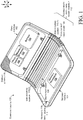
- FIGS. 1 and 2 collectively show an example of a computing device 100.
- FIG. 2 is an exploded view of the computing device from a similar perspective as FIG. 1 .
- computing device 100 has first and second portions 102 and 104 that are rotatably secured together by a multi-pivot hinge 106.
- a flexible multi-pivot hinge cover 108 can extend from the first portion 102 to the second portion 104 to cover the multi-pivot hinge 106.
- the flexible multi-pivot hinge cover 108 covers the 'backside' or 'outside' (e.g., facing away from the reader) of the computing device 100. In other cases, the flexible multi-pivot hinge cover 108 can cover the inside surface or both the inside and outside surfaces. In this implementation the flexible multi-pivot hinge cover 108 can be secured to the multi-pivot hinge 106 by opposing end securing elements 110(1) and 110(2). In this case, the end securing elements 110 can mimic a profile of the multi-pivot hinge 106 to appear generally continuous along the width of the computer (e.g., in the y reference direction). The multi-pivot hinge 106, the flexible multi-pivot hinge cover 108, and/or securing elements, such as end securing elements 110, can be thought of as a flexible multi-pivot hinge cover assembly 112.
- computing device 100 can also include an input element or device 114.
- the input device 114 is manifest as a keyboard 116.
- the computing device can also include a display screen 118, such as a touch sensitive display screen.
- the computing device can also include a processor 120, memory/storage 122, a battery 124, and/or a graphics processor 126, among other components. These elements can be positioned in the first portion 102 and/or second portion 104. (Components 114-126 are not shown in FIG. 2 ).
- Flexible multi-pivot hinge cover assembly 112 can be secured to the first and second portions 102 and 104 to allow rotation therebetween.
- the flexible multi-pivot hinge cover assembly 112 can be secured to the first and second portions in a relatively permanent manner (e.g., in a manner that is not intended to be readily separable by an end use consumer), such as illustrated in FIGS. 1-2 .
- the flexible multi-pivot hinge cover assembly 112 can be secured to the first and second portions in a relatively quickly attachable/detachable manner (e.g., in a manner that is intended to be readily separable by the end use consumer).
- FIG. 3 One such example of this latter configuration is shown in FIG. 3 .
- FIG. 3 shows a view that is similar to the view of FIG. 1 .
- computing device 100A includes first and second portions 102 and 104 that are rotatably secured by flexible multi-pivot hinge cover assembly 112A.
- the flexible multi-pivot hinge cover assembly 112A is configured to allow an end use consumer to easily detach either or both of the first and second portions 102 and 104 from the flexible multi-pivot hinge cover assembly 112A as indicated by arrow 302.
- the flexible multi-pivot hinge cover assembly 112A can include a quick attach/detach assembly 304.
- the quick attach/detach assembly 304 may include cooperatively operating elements or interfaces 306 and 308 located on the first portion 102 and the flexible multi-pivot hinge cover assembly 112A, respectively.
- element 306 can be manifest as a latch and element 308 can be manifest as a receiver.
- the latch can engage the receiver to removeably couple the first portion 102 with the flexible multi-pivot hinge cover assembly 112A.
- the elements 306 and 308 may magnetically couple to one another in a manner that can be overcome by the user to separate the first portion from the flexible multi-pivot hinge cover assembly 112A.
- Other quick attach/detach assemblies 304 are contemplated. Note further that alternatively or additionally to mechanically coupling the flexible multi-pivot hinge cover assembly 112A to the first and/or second portions 102 and 104, the quick attach/detach assembly 304 can detachably electrically couple electronic components of the first and second portions. For instance, the quick attach/detach assembly 304 may electrically couple/decouple processor 120, storage/memory 122, and/or battery 124 from the first portion 102 to graphics processor 126 in the second portion 104.
- first portion 102 may be operated as a stand-alone tablet device, and then may be attached to second portion 104 via flexible multi-pivot hinge cover assembly 112A to form a device more akin to a laptop device.
- a user may also be able to exchange first portion 102 or second portion 104 for application-specific devices.
- an individual second portion may include a keyboard and/or a touchscreen.
- the user may attach a first touchscreen as the first portion and a second touchscreen as second portion, and utilize the device like a book.
- a user may attach a touchscreen as the first portion and an input device, such as a keyboard and trackpad, as the second portion, and utilize the device like a laptop.
- Other configurations and implementations are contemplated.
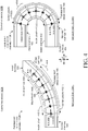
- FIG. 4 shows side views of the flexible multi-pivot hinge cover assembly 112B that is similar to the flexible multi-pivot hinge cover assembly 112 introduced in FIG. 1 .
- Instance One shows the flexible multi-pivot hinge cover assembly 112B in an open or deployed position and Instance Two shows a closed or storage position.
- the computing device 100B can be thought of as having an inner surface 402 and an outer surface 404.
- FIG. 4 shows hinge axes 406 (not all of which are designated) of the flexible multi-pivot hinge cover assembly 112B.
- a neutral axis 408 of the flexible multi-pivot hinge cover assembly 112B passes through (e.g., is defined by) the hinge axes 406.
- an inner hinge length 410 (measured at the inner surface 402) and an outer hinge length 412 (measured at the outer surface 404) can change as the position changes.
- the inner length 410(2) is shorter than the inner length 410(1) in the open position of Instance One.
- the outer length 412 increases as the flexible multi-pivot hinge cover assembly 112B is closed.
- outer length 412(2) of Instance Two is greater than outer length 412(1) of Instance One.
- the flexible multi-pivot hinge cover can stretch or otherwise expand to accommodate the increase in length.
- the flexible multi-pivot hinge cover can be stretchable such that it can be stretched to accommodate the longer closed position and then return to its original configuration and appearance when the multi-pivot hinge is opened.
- the multi-pivot hinge 106 can be thought of as a collection or set of hinge axes 406 interposed between hinge unit bodies 414 (not all of which are designated with specificity to avoid clutter on the drawing page).
- the hinge unit bodies 414 can be manifest as regular geometric shapes (when viewed along the y reference axis). For instance, in the illustrated configuration of FIG. 4 , the hinge unit bodies can approximate a portion of a trapezoid. Though not specifically discussed below, in the illustrated configuration of FIG. 5 , the hinge unit bodies 414 can approximate a portion of a rectangle. In these implementations the hinge unit bodies are all the same shape. In other implementations, the hinge unit bodies can have different shapes from one another.
- FIG. 5 shows three views of an alternative computing device 100C.
- Instance One shows the computing device in an open position.
- Instance Two shows the computing device in an intermediate position and
- Instance Three shows the computing device in a closed position.
- This implementation can include a flexible display or flexible display screen 502 positioned on inner surface 402.
- Various flexible display technologies such as flexible organic light emitting diode (OLED) or electronic paper, can be utilized.
- the first portion 102, the multi-pivot hinge cover assembly 112C, and the second portion 104 can collectively define inner surface 402 and opposite outer surface 404 of the computing device 100C.
- the multi-pivot hinge cover assembly 112C can be configured to maintain a length 504 of the inner surface 402 during rotation of the first and second portions 102 and 104 while accommodating changes in length 506 of the outer surface 404 during the rotation. (The inner surface length 504 and the outer surface length 506 are only designated relative to Instance Two due to space constraints on the drawing page of FIG. 5 .)
- the flexible multi-pivot hinge cover assembly 112C can allow the first and second portions 102 and 104 to be rotated through a range of rotations.
- the closed position of Instance Three orients the first and second portions at an angle ⁇ of approximately zero degrees to one another. (In this case, the closed position is actually less than zero degrees since zero degrees would entail the first portion being juxtaposed over and parallel to the second portion.
- Instance Two shows the two portions 102 and 104 rotated to a typical use position for notebook (e.g., laptop) type devices where the angle ⁇ is an obtuse angle.
- Instance One shows a 'flat' configuration where angle ⁇ is about 180 degrees. This position can be used in an e-reader scenario.
- the range of rotation can continue until the first portion is oriented under the second portion at an angle ⁇ of about 360 degrees.
- computing device 100C could also be implemented as a smart watch.
- a band of the smartwatch could be attached to the second portion 104 so that the band extends into and out of the drawing page in the y and -y reference directions. The user could close the smartwatch, such as in Instance Three, when not looking at the smartwatch to protect the flexible display 502.
- the user can open the smartwatch to the orientation of Instance One or Instance Two to have a relatively large surface area of the flexible display on a device that is relatively compact in the closed position of Instance Three.
- the combination of the flexible multi-pivot hinge cover assembly 112C and the flexible display can allow the smartwatch (or other device) to have nearly twice as much screen area as a traditional device having the same footprint as the smartwatch does in the closed configuration.
- another flexible multi-pivot hinge cover assembly could be utilized in (or as) the band of the smartwatch.
- FIGS. 6-11C offer additional details about the elements of computing device 100 while illustrating a method of manufacture of flexible multi-pivot hinge cover assembly 112.
- FIG. 6 shows flexible multi-pivot hinge cover 108 (actually a precursor thereof) and a fixture 602.
- the flexible multi-pivot hinge cover 108 can be positioned on the fixture 602 as indicated at 604.
- the fixture can impart a specific shape in the flexible multi-pivot hinge cover 108.
- the shape of the fixture as indicated generally at 606 can mimic a shape of the flexible multi-pivot hinge cover assembly 112 in the deployed position (see FIG. 1-2 ).
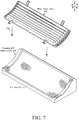
- the fixture can include end structures 608 that can match dimensions of the multi-pivot hinge (see FIG. 7 ) to hold the multi-pivot hinge and shape the flexible multi-pivot hinge cover 108.
- FIGS. 7-8 show that the multi-pivot hinge 106 can be positioned on the flexible multi-pivot hinge cover 108 in the fixture 602 as indicated at 702.
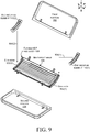
- FIG. 9 shows side edges 902(1) and 902(2) of the flexible multi-pivot hinge cover 108 shaped to roll over the side edges of the multi-pivot hinge 106.
- the process of shaping while not specifically shown, can be performed in various ways, such as with a fabric edge curling fixture.
- the shaped side edges 902 can be held in place by end securing elements 110 as indicated by arrows 904.
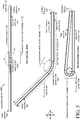
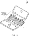
- FIG. 10 shows how the ends 1002 of the multi-pivot hinge 106 can be interfaced to the first and second portions as indicated at 1004.
- the ends 1002 can then be secured in the first and second portions with various mechanisms, such as clamps, glue, screws, etc.
- the act of securing the multi-pivot hinge 106 to the first and second portions 102 and 104 can also be utilized to secure the top and bottom edges of the flexible multi-pivot hinge cover 108.
- the ends of the flexible multi-pivot hinge cover can be sandwiched between the first and second portions and the multi-pivot hinge 106 to complete the flexible multi-pivot hinge cover assembly 112. This aspect is shown in more detail below relative to FIGS. 11-11C .
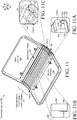
- FIG. 11 shows the computing device 100 with the first portion 102 and the second portion 104 assembled with the flexible multi-pivot hinge cover assembly 112.
- the flexible multi-pivot hinge cover 108 can be secured, at least in part, by being compressed between individual elements.
- FIG. 11A shows an enlarged view of how the flexible multi-pivot hinge cover 108 can be secured between the end securing element 110(1) and the multi-pivot hinge 106.
- the flexible multi-pivot hinge cover has been shaped so that it is secured between two different opposing surfaces of the end securing element 110(1) and the multi-pivot hinge 106.
- first two opposing surfaces are manifest as 1102 of the multi-pivot hinge 106 and 1104 of the end securing element 110(1).
- the second two opposing surfaces are manifest as 1106 of the multi-pivot hinge 106 and 1108 of the end securing element 110(1).
- these two sets of different opposing surfaces 1102/1104 and 1106/1108 are oriented at approximately right angles to one another to enhance the retaining force on flexible multi-pivot hinge cover 108.
- FIG. 11B shows how flexible multi-pivot hinge cover 108 can be secured between the multi-pivot hinge 106 and the second portion 104 (and similarly first portion 102).
- second portion 104 includes a protruding bearing surface 1110 that helps to ensure firm compression of the flexible multi-pivot hinge cover 108 between the multi-pivot hinge 106 and the second portion 104.
- the protruding bearing surface 1110 can ensure adequate compression of the flexible multi-pivot hinge cover 108 before other portions of the second portion 104 contact the multi-pivot hinge 106.
- FIG. 11C shows a corner region of the flexible multi-pivot hinge cover assembly 112.
- the corner region can be thought of as an intersection between a portion (e.g., edge) of the flexible multi-pivot hinge cover 108 secured generally along the y reference axis between the first portion 102 and the multi-pivot hinge 106 and another portion (e.g., edge) secured generally along the x reference axis between the multi-pivot hinge 106 and the end securing element 110(1).
- extra material of the flexible multi-pivot hinge cover 108 may be encountered.
- the end securing element 110(1) can include a void or pocket to accommodate this extra material so that the extra material does not interfere with securing the flexible multi-pivot hinge cover 108 to the computing device 100.
- the pocket is difficult to visualize in the line drawing of FIG. 11C , but a general location of the pocket is indicated at 1112.
- FIGS. 11-11C illustrate an implementation where all edges of the flexible multi-pivot hinge cover 108 are trapped between elements of the computing device 100. This configuration can ensure that no edges of the flexible multi-pivot hinge cover 108 are exposed in a manner that can allow them to be snagged or otherwise come loose during use. This configuration can protect the user from the underlying multi-pivot hinge in a manner that is both attractive and durable.
- the flexible multi-pivot hinge cover 108 can be made from various materials, such as fabrics, polymers, composites, elastomers, woven or knitted materials, skins, leathers and/or any other covering that is capable of expansion and contraction while remaining taught through the entire range of the hinge.
- a single (e.g. continuous) sheet can be utilized so that there are no seams exposed on the device (e.g. that can be seen by the user).
- Other elements of the flexible multi-pivot hinge cover assembly 112 can be made from various materials, such as sheet metals, die cast metals, and/or molded plastics, among others, or any combination of these materials.
- Flexible multi-pivot hinge cover assembly 112 can be utilized with any type of computing device, such as but not limited to notebook computers, smart phones, wearable smart devices, and/or other types of existing, developing, and/or yet to be developed computing devices.
- One example is manifest as a computing device that has a first portion that includes a display screen and a second portion that includes an input device.
- the example can also include a multi-pivot hinge rotatably securing the first portion and the second portion and configured to rotate around multiple hinge axes to provide rotation between the first and second portions.
- the example can further include a flexible multi-pivot hinge cover that covers the multi-pivot hinge between the first portion and the second portion and that is configured to accommodate length changes of the multi-pivot hinge during the rotation.
- the example can also include opposing end securing elements configured to secure the flexible multi-pivot hinge cover to the multi-pivot hinge between the first and second portions.
- the display screen is a flexible display screen that extends over the first portion, the multi-pivot hinge, and the second portion.
- the example can also include a multi-pivot hinge rotatably securing the first portion and the second portion and configured to rotate around multiple hinge axes to provide rotation between the first and second portions.
- the example can further include a flexible multi-pivot hinge cover that covers the multi-pivot hinge between the first portion and the second portion without any exposed edges.
- the multi-pivot hinge is configured to rotate the first and second portions from an open orientation where the first and second portions define an obtuse angle therebetween to a closed orientation where the first portion is juxtaposed over the second portion and wherein the flexible multi-pivot hinge cover is configured to stretch in the closed orientation.
- the flexible multi-pivot hinge cover comprises a single piece of elastic fabric.
- first portion, the multi-pivot hinge, and the second portion collectively define an inner surface and an opposite outer surface and wherein the multi-pivot hinge is configured to maintain a length of the inner surface during rotation of the first and second portions and wherein the flexible multi-pivot hinge cover is configured to accommodate changes in length of the outer surface during the rotation.
- any combination of the above and/or below examples further including a flexible display secured to the inner surface.
- multi-pivot hinge comprises multiple hinge axes interposed between multiple hinge unit bodies.
- hinge unit bodies are all a same shape or wherein the hinge unit bodies have different shapes.
- hinge unit bodies are regular geometric shapes.
- Another example is manifest as a first portion and a second portion.
- the example can also include a flexible multi-pivot hinge cover assembly rotatably securing the first and second portions.
- the second portion comprises a base of a smart watch.
- any combination of the above and/or below examples further including another flexible multi-pivot hinge cover assembly comprising a band of the smart watch.
Description
- The present invention relates to a computing device comprising a first portion, a second portion, and a multi-pivot hinge rotatably securing the first portion and the second portion, as known from
US 2013/0219663 A1 ,KR 2014 0049911 A US 2006/079277 A1 . - The accompanying drawings illustrate implementations of the concepts conveyed in the present document. Features of the illustrated implementations can be more readily understood by reference to the following description taken in conjunction with the accompanying drawings. Like reference numbers in the various drawings are used wherever feasible to indicate like elements. Further, the left-most numeral of each reference number conveys the FIG. and associated discussion where the reference number is first introduced.
-
FIG. 1 shows a perspective view of an example device that includes a flexible multi-pivot hinge cover assembly example in accordance with some implementations of the present concepts. -
FIG. 2 shows an exploded perspective view of the example device ofFIG. 1 . -
FIG. 3 shows a perspective view of another example device that includes a flexible multi-pivot hinge cover assembly example in accordance with some implementations of the present concepts. -
FIG. 4 shows side elevational views of another example device that is similar to the device ofFIG. 1 . -
FIG. 5 shows side elevational views of another example device that includes a flexible multi-pivot hinge cover assembly example in accordance with some implementations of the present concepts. -
FIGS. 6-11C show an example of an assembly process for the example device ofFIG. 1 in accordance with some implementations of the present concepts. - The present concepts relate to flexible multi-pivot hinge covers for multi-pivot or multi-axis hinges. Computing devices can employ multi-pivot hinges to rotatably secure portions of the computing device. The present concepts can provide flexible multi-pivot hinge covers over the multi-pivot hinges to protect the hinges from foreign objects and/or protect a user of the computing device from being pinched by the multi-pivot hinges during rotation.
- Introductory
FIGS. 1 and2 collectively show an example of acomputing device 100.FIG. 2 is an exploded view of the computing device from a similar perspective asFIG. 1 . In this example,computing device 100 has first andsecond portions multi-pivot hinge 106. A flexiblemulti-pivot hinge cover 108 can extend from thefirst portion 102 to thesecond portion 104 to cover themulti-pivot hinge 106. - In this case, the flexible
multi-pivot hinge cover 108 covers the 'backside' or 'outside' (e.g., facing away from the reader) of thecomputing device 100. In other cases, the flexiblemulti-pivot hinge cover 108 can cover the inside surface or both the inside and outside surfaces. In this implementation the flexiblemulti-pivot hinge cover 108 can be secured to themulti-pivot hinge 106 by opposing end securing elements 110(1) and 110(2). In this case, theend securing elements 110 can mimic a profile of themulti-pivot hinge 106 to appear generally continuous along the width of the computer (e.g., in the y reference direction). Themulti-pivot hinge 106, the flexiblemulti-pivot hinge cover 108, and/or securing elements, such asend securing elements 110, can be thought of as a flexible multi-pivothinge cover assembly 112. - As shown in
FIG. 1 , in various configurations,computing device 100 can also include an input element ordevice 114. In this case theinput device 114 is manifest as akeyboard 116. Other implementations can employ other input devices. In this example, the computing device can also include adisplay screen 118, such as a touch sensitive display screen. The computing device can also include aprocessor 120, memory/storage 122, abattery 124, and/or agraphics processor 126, among other components. These elements can be positioned in thefirst portion 102 and/orsecond portion 104. (Components 114-126 are not shown inFIG. 2 ). - Flexible multi-pivot
hinge cover assembly 112 can be secured to the first andsecond portions hinge cover assembly 112 can be secured to the first and second portions in a relatively permanent manner (e.g., in a manner that is not intended to be readily separable by an end use consumer), such as illustrated inFIGS. 1-2 . Alternatively, the flexible multi-pivothinge cover assembly 112 can be secured to the first and second portions in a relatively quickly attachable/detachable manner (e.g., in a manner that is intended to be readily separable by the end use consumer). One such example of this latter configuration is shown inFIG. 3 . -
FIG. 3 shows a view that is similar to the view ofFIG. 1 . In this case,computing device 100A includes first andsecond portions second portions arrow 302. In this example the flexible multi-pivot hinge cover assembly 112A can include a quick attach/detach assembly 304. The quick attach/detach assembly 304 may include cooperatively operating elements orinterfaces first portion 102 and the flexible multi-pivot hinge cover assembly 112A, respectively. - In one example,
element 306 can be manifest as a latch andelement 308 can be manifest as a receiver. The latch can engage the receiver to removeably couple thefirst portion 102 with the flexible multi-pivot hinge cover assembly 112A. In another example, theelements detach assemblies 304 are contemplated. Note further that alternatively or additionally to mechanically coupling the flexible multi-pivot hinge cover assembly 112A to the first and/orsecond portions detach assembly 304 can detachably electrically couple electronic components of the first and second portions. For instance, the quick attach/detach assembly 304 may electrically couple/decouple processor 120, storage/memory 122, and/orbattery 124 from thefirst portion 102 tographics processor 126 in thesecond portion 104. - Thus, the quick attach/
detach assembly 304 can allow the user to be able to detachfirst portion 102 orsecond portion 104 to use either portion independent of the other. For example,first portion 102 may be operated as a stand-alone tablet device, and then may be attached tosecond portion 104 via flexible multi-pivot hinge cover assembly 112A to form a device more akin to a laptop device. A user may also be able to exchangefirst portion 102 orsecond portion 104 for application-specific devices. For example, an individual second portion may include a keyboard and/or a touchscreen. In certain scenarios, the user may attach a first touchscreen as the first portion and a second touchscreen as second portion, and utilize the device like a book. In other scenarios, a user may attach a touchscreen as the first portion and an input device, such as a keyboard and trackpad, as the second portion, and utilize the device like a laptop. Other configurations and implementations are contemplated. -
FIG. 4 shows side views of the flexible multi-pivothinge cover assembly 112B that is similar to the flexible multi-pivothinge cover assembly 112 introduced inFIG. 1 . Instance One shows the flexible multi-pivothinge cover assembly 112B in an open or deployed position and Instance Two shows a closed or storage position. For purposes of explanation thecomputing device 100B can be thought of as having aninner surface 402 and anouter surface 404.FIG. 4 shows hinge axes 406 (not all of which are designated) of the flexible multi-pivothinge cover assembly 112B. Aneutral axis 408 of the flexible multi-pivothinge cover assembly 112B passes through (e.g., is defined by) thehinge axes 406. As the flexible multi-pivothinge cover assembly 112B is rotated between the open position and the closed position the length of the neutral axis remains relatively constant. However, an inner hinge length 410 (measured at the inner surface 402) and an outer hinge length 412 (measured at the outer surface 404) can change as the position changes. For example, in the closed position of Instance Two, the inner length 410(2) is shorter than the inner length 410(1) in the open position of Instance One. In contrast, theouter length 412 increases as the flexible multi-pivothinge cover assembly 112B is closed. For example, outer length 412(2) of Instance Two is greater than outer length 412(1) of Instance One. In some implementations, the flexible multi-pivot hinge cover can stretch or otherwise expand to accommodate the increase in length. In some cases, the flexible multi-pivot hinge cover can be stretchable such that it can be stretched to accommodate the longer closed position and then return to its original configuration and appearance when the multi-pivot hinge is opened. - Note that from one perspective, the
multi-pivot hinge 106 can be thought of as a collection or set of hinge axes 406 interposed between hinge unit bodies 414 (not all of which are designated with specificity to avoid clutter on the drawing page). In some implementations, thehinge unit bodies 414 can be manifest as regular geometric shapes (when viewed along the y reference axis). For instance, in the illustrated configuration ofFIG. 4 , the hinge unit bodies can approximate a portion of a trapezoid. Though not specifically discussed below, in the illustrated configuration ofFIG. 5 , thehinge unit bodies 414 can approximate a portion of a rectangle. In these implementations the hinge unit bodies are all the same shape. In other implementations, the hinge unit bodies can have different shapes from one another. -
FIG. 5 shows three views of analternative computing device 100C. Instance One shows the computing device in an open position. Instance Two shows the computing device in an intermediate position and Instance Three shows the computing device in a closed position. This implementation can include a flexible display orflexible display screen 502 positioned oninner surface 402. Various flexible display technologies, such as flexible organic light emitting diode (OLED) or electronic paper, can be utilized. - From one perspective, the
first portion 102, the multi-pivothinge cover assembly 112C, and thesecond portion 104 can collectively defineinner surface 402 and oppositeouter surface 404 of thecomputing device 100C. The multi-pivothinge cover assembly 112C can be configured to maintain alength 504 of theinner surface 402 during rotation of the first andsecond portions length 506 of theouter surface 404 during the rotation. (Theinner surface length 504 and theouter surface length 506 are only designated relative to Instance Two due to space constraints on the drawing page ofFIG. 5 .) - Note that the flexible multi-pivot
hinge cover assembly 112C can allow the first andsecond portions hinge cover assembly 112C can maintain a minimum bend radius r which can protect theflexible display 502 from damage, such as creasing.) Instance Two shows the twoportions flexible display 502 is capable of stretching in plane or is otherwise mechanically free to float or move onfirst portion 102,second portion 104, and/or the hinge section in a direction perpendicular to the axis of rotation, the range of rotation can continue until the first portion is oriented under the second portion at an angle α of about 360 degrees. - Note further, that while the illustrated configuration can be utilized for relatively large devices, such as notebooks, e-readers, and smart phones, this implementation also lends itself to relatively smaller implementations, such as wearable smart devices. For instance,
computing device 100C could also be implemented as a smart watch. For example, a band of the smartwatch could be attached to thesecond portion 104 so that the band extends into and out of the drawing page in the y and -y reference directions. The user could close the smartwatch, such as in Instance Three, when not looking at the smartwatch to protect theflexible display 502. When the user wants to view theflexible display 502, the user can open the smartwatch to the orientation of Instance One or Instance Two to have a relatively large surface area of the flexible display on a device that is relatively compact in the closed position of Instance Three. Stated another way, the combination of the flexible multi-pivothinge cover assembly 112C and the flexible display can allow the smartwatch (or other device) to have nearly twice as much screen area as a traditional device having the same footprint as the smartwatch does in the closed configuration. Alternatively or additionally to utilizing the flexible multi-pivothinge cover assembly 112C to couple the first andsecond portions -
FIGS. 6-11C offer additional details about the elements ofcomputing device 100 while illustrating a method of manufacture of flexible multi-pivothinge cover assembly 112. -
FIG. 6 shows flexible multi-pivot hinge cover 108 (actually a precursor thereof) and afixture 602. The flexiblemulti-pivot hinge cover 108 can be positioned on thefixture 602 as indicated at 604. The fixture can impart a specific shape in the flexiblemulti-pivot hinge cover 108. For instance, in this case, the shape of the fixture as indicated generally at 606 can mimic a shape of the flexible multi-pivothinge cover assembly 112 in the deployed position (seeFIG. 1-2 ). In another example, the fixture can include endstructures 608 that can match dimensions of the multi-pivot hinge (seeFIG. 7 ) to hold the multi-pivot hinge and shape the flexiblemulti-pivot hinge cover 108. -
FIGS. 7-8 show that themulti-pivot hinge 106 can be positioned on the flexiblemulti-pivot hinge cover 108 in thefixture 602 as indicated at 702. -
FIG. 9 shows side edges 902(1) and 902(2) of the flexiblemulti-pivot hinge cover 108 shaped to roll over the side edges of themulti-pivot hinge 106. The process of shaping, while not specifically shown, can be performed in various ways, such as with a fabric edge curling fixture. The shaped side edges 902 can be held in place byend securing elements 110 as indicated byarrows 904. -
FIG. 10 shows how theends 1002 of themulti-pivot hinge 106 can be interfaced to the first and second portions as indicated at 1004. The ends 1002 can then be secured in the first and second portions with various mechanisms, such as clamps, glue, screws, etc. The act of securing themulti-pivot hinge 106 to the first andsecond portions multi-pivot hinge cover 108. For instance, the ends of the flexible multi-pivot hinge cover can be sandwiched between the first and second portions and themulti-pivot hinge 106 to complete the flexible multi-pivothinge cover assembly 112. This aspect is shown in more detail below relative toFIGS. 11-11C . -
FIG. 11 shows thecomputing device 100 with thefirst portion 102 and thesecond portion 104 assembled with the flexible multi-pivothinge cover assembly 112. In this implementation, the flexiblemulti-pivot hinge cover 108 can be secured, at least in part, by being compressed between individual elements. For instance,FIG. 11A shows an enlarged view of how the flexiblemulti-pivot hinge cover 108 can be secured between the end securing element 110(1) and themulti-pivot hinge 106. In this case, the flexible multi-pivot hinge cover has been shaped so that it is secured between two different opposing surfaces of the end securing element 110(1) and themulti-pivot hinge 106. In this example the first two opposing surfaces are manifest as 1102 of themulti-pivot hinge multi-pivot hinge surfaces 1102/1104 and 1106/1108 are oriented at approximately right angles to one another to enhance the retaining force on flexiblemulti-pivot hinge cover 108. -
FIG. 11B shows how flexiblemulti-pivot hinge cover 108 can be secured between themulti-pivot hinge 106 and the second portion 104 (and similarly first portion 102). In this implementation,second portion 104 includes a protrudingbearing surface 1110 that helps to ensure firm compression of the flexiblemulti-pivot hinge cover 108 between themulti-pivot hinge 106 and thesecond portion 104. The protrudingbearing surface 1110 can ensure adequate compression of the flexiblemulti-pivot hinge cover 108 before other portions of thesecond portion 104 contact themulti-pivot hinge 106. -
FIG. 11C shows a corner region of the flexible multi-pivothinge cover assembly 112. The corner region can be thought of as an intersection between a portion (e.g., edge) of the flexiblemulti-pivot hinge cover 108 secured generally along the y reference axis between thefirst portion 102 and themulti-pivot hinge 106 and another portion (e.g., edge) secured generally along the x reference axis between themulti-pivot hinge 106 and the end securing element 110(1). In this corner region extra material of the flexiblemulti-pivot hinge cover 108 may be encountered. The end securing element 110(1) can include a void or pocket to accommodate this extra material so that the extra material does not interfere with securing the flexiblemulti-pivot hinge cover 108 to thecomputing device 100. The pocket is difficult to visualize in the line drawing ofFIG. 11C , but a general location of the pocket is indicated at 1112. -
FIGS. 11-11C illustrate an implementation where all edges of the flexiblemulti-pivot hinge cover 108 are trapped between elements of thecomputing device 100. This configuration can ensure that no edges of the flexiblemulti-pivot hinge cover 108 are exposed in a manner that can allow them to be snagged or otherwise come loose during use. This configuration can protect the user from the underlying multi-pivot hinge in a manner that is both attractive and durable. - The flexible
multi-pivot hinge cover 108 can be made from various materials, such as fabrics, polymers, composites, elastomers, woven or knitted materials, skins, leathers and/or any other covering that is capable of expansion and contraction while remaining taught through the entire range of the hinge. In some implementations, a single (e.g. continuous) sheet can be utilized so that there are no seams exposed on the device (e.g. that can be seen by the user). Other elements of the flexible multi-pivothinge cover assembly 112 can be made from various materials, such as sheet metals, die cast metals, and/or molded plastics, among others, or any combination of these materials. - Flexible multi-pivot
hinge cover assembly 112 can be utilized with any type of computing device, such as but not limited to notebook computers, smart phones, wearable smart devices, and/or other types of existing, developing, and/or yet to be developed computing devices. - Various methods of manufacture, assembly, and use for flexible multi-pivot hinge cover assemblies are contemplated beyond those shown above relative to
FIGS 1-11C . - Various examples are described above. Additional examples are described below. One example is manifest as a computing device that has a first portion that includes a display screen and a second portion that includes an input device. The example can also include a multi-pivot hinge rotatably securing the first portion and the second portion and configured to rotate around multiple hinge axes to provide rotation between the first and second portions. The example can further include a flexible multi-pivot hinge cover that covers the multi-pivot hinge between the first portion and the second portion and that is configured to accommodate length changes of the multi-pivot hinge during the rotation. The example can also include opposing end securing elements configured to secure the flexible multi-pivot hinge cover to the multi-pivot hinge between the first and second portions.
- Any combination of the above and/or below examples where the display screen is a flexible display screen that extends over the first portion, the multi-pivot hinge, and the second portion.
- Any combination of the above and/or below examples where a neutral axis of the multi-pivot hinge is against the flexible display screen.
- Any combination of the above and/or below examples where the flexible multi-pivot hinge cover completely encloses the multi-pivot hinge or where the flexible multi-pivot hinge cover covers only an inside surface of the multi-pivot hinge or an outside surface of the multi-pivot hinge.
- Any combination of the above and/or below examples where a range of rotation of the multi-pivot hinge is less than or equal to 180 degrees or wherein the range of rotation is between 180 degrees and 360 degrees.
- Another example is manifest as a first portion and a second portion. The example can also include a multi-pivot hinge rotatably securing the first portion and the second portion and configured to rotate around multiple hinge axes to provide rotation between the first and second portions. The example can further include a flexible multi-pivot hinge cover that covers the multi-pivot hinge between the first portion and the second portion without any exposed edges.
- Any combination of the above and/or below examples where the multi-pivot hinge is configured to rotate the first and second portions from an open orientation where the first and second portions define an obtuse angle therebetween to a closed orientation where the first portion is juxtaposed over the second portion and wherein the flexible multi-pivot hinge cover is configured to stretch in the closed orientation.
- Any combination of the above and/or below examples where a first edge of the flexible multi-pivot hinge cover is secured between the first portion and the multi-pivot hinge and a second edge of the flexible multi-pivot hinge cover is secured between the second portion and the multi-pivot hinge.
- Any combination of the above and/or below examples where a third edge of the flexible multi-pivot hinge cover is secured between the multi-pivot hinge and a first end securing element and a fourth edge of the flexible multi-pivot hinge cover is secured between the multi-pivot hinge and the second end securing element.
- Any combination of the above and/or below examples where the flexible multi-pivot hinge cover comprises a single piece of elastic fabric.
- Any combination of the above and/or below examples where the first portion, the multi-pivot hinge, and the second portion collectively define an inner surface and an opposite outer surface and wherein the multi-pivot hinge is configured to maintain a length of the inner surface during rotation of the first and second portions and wherein the flexible multi-pivot hinge cover is configured to accommodate changes in length of the outer surface during the rotation.
- Any combination of the above and/or below examples where the multi-pivot hinge maintains a minimum bend radius throughout the rotation.
- Any combination of the above and/or below examples further including a flexible display secured to the inner surface.
- Any combination of the above and/or below examples where the multi-pivot hinge comprises multiple hinge axes interposed between multiple hinge unit bodies.
- Any combination of the above and/or below examples where the hinge unit bodies are all a same shape or wherein the hinge unit bodies have different shapes.
- Any combination of the above and/or below examples where the hinge unit bodies are regular geometric shapes.
- Another example is manifest as a first portion and a second portion. The example can also include a flexible multi-pivot hinge cover assembly rotatably securing the first and second portions.
- Any combination of the above and/or below examples where the second portion comprises a base of a smart watch.
- Any combination of the above and/or below examples where the flexible multi-pivot hinge cover assembly allows the first portion to be rotated away from the second portion during use and closed upon the first portion when not in use.
- Any combination of the above and/or below examples further including another flexible multi-pivot hinge cover assembly comprising a band of the smart watch.
- Although techniques, methods, devices, systems, etc., pertaining to flexible multi-pivot hinge cover assemblies are described in language specific to structural features and/or methodological acts, it is to be understood that the subject matter defined in the appended claims is not necessarily limited to the specific features or acts described. Rather, the specific features and acts are disclosed as exemplary forms of implementing the claimed methods, devices, systems, etc.
Claims (14)
- A computing device (100), comprising:a first portion (102) and a second portion (104);a multi-pivot hinge (106) rotatably securing the first portion and the second portion and configured to rotate around multiple hinge axes to provide rotation between the first and second portions; and,a flexible multi-pivot hinge cover (108) that covers the multi-pivot hinge between the first portion and the second portion without any exposed edges, wherein side edges (902(1), 902(2)) of the flexible multi-pivot hinge cover (108) are shaped to roll over side edges of the multi-pivot hinge (106), further characterised in that the shaped side edges of the flexible multi-pivot hinge cover are held in place by end securing elements (110(1), 110(2)) against the multi-pivot hinge (106).
- The computing device of claim 1, wherein the multi-pivot hinge (106) is configured to rotate the first and second portions from an open orientation where the first and second portions define an obtuse angle (α) therebetween to a closed orientation where the first portion is juxtaposed over the second portion and wherein the flexible multi-pivot hinge cover (108) is configured to stretch in the closed orientation.
- The computing device of claim 1, wherein a first edge (902(1)) of the flexible multi-pivot hinge cover is secured between the first portion and the multi-pivot hinge and a second edge (902(2)) of the flexible multi-pivot hinge cover is secured between the second portion and the multi-pivot hinge.
- The computing device of claim 3, wherein the side edges (902(1), 902(2)) of the flexible multi-pivot hinge cover are secured between the multi-pivot hinge (106) and the end securing elements (110(1), 110(2)).
- The computing device of claim 1, wherein the flexible multi-pivot hinge cover (108) comprises a single piece of elastic fabric.
- The computing device of claim 1, wherein the first portion, the multi-pivot hinge, and the second portion collectively define a inner surface (402) and an opposite outer surface (404) and wherein the multi-pivot hinge (106) is configured to maintain a length of the inner surface (410) during rotation of the first and second portions and wherein the flexible multi-pivot hinge cover (108) is configured to accommodate changes in length of the outer surface (412) during the rotation.
- The computing device of claim 6, wherein the multi-pivot hinge (106) maintains a minimum bend radius throughout the rotation.
- The computing device of claim 7, further comprising a flexible display (502) secured to the inner surface (410).
- The computing device of claim 1, wherein the multi-pivot hinge (106) comprises multiple hinge axes (406) interposed between multiple hinge unit bodies (414).
- The computing device of claim 9, wherein the hinge unit bodies (414) are all a same shape or wherein the hinge unit bodies have different shapes.
- The computing device of claim 9, wherein the hinge unit bodies (414) are regular geometric shapes.
- The computing device of claim 1, wherein the second portion (104) comprises a base of a smart watch.
- The computing device of claim 12, wherein the flexible multi-pivot hinge (106) allows the first portion to be rotated away from the second portion during use and closed upon the first portion when not in use.
- The computing device of claim 13, further comprising another flexible multi-pivot hinge comprising a band of the smart watch.
Applications Claiming Priority (2)
| Application Number | Priority Date | Filing Date | Title |
|---|---|---|---|
| US14/588,138 US9851759B2 (en) | 2014-12-31 | 2014-12-31 | Multi-pivot hinge cover |
| PCT/US2015/064173 WO2016109123A1 (en) | 2014-12-31 | 2015-12-07 | Multi-pivot hinge cover |
Publications (2)
| Publication Number | Publication Date |
|---|---|
| EP3241087A1 EP3241087A1 (en) | 2017-11-08 |
| EP3241087B1 true EP3241087B1 (en) | 2018-09-26 |
Family
ID=55022716
Family Applications (1)
| Application Number | Title | Priority Date | Filing Date |
|---|---|---|---|
| EP15816331.1A Active EP3241087B1 (en) | 2014-12-31 | 2015-12-07 | Multi-pivot hinge cover |
Country Status (11)
| Country | Link |
|---|---|
| US (1) | US9851759B2 (en) |
| EP (1) | EP3241087B1 (en) |
| JP (1) | JP6660955B2 (en) |
| KR (1) | KR102374504B1 (en) |
| CN (1) | CN107111341B (en) |
| AU (1) | AU2015374531B2 (en) |
| BR (1) | BR112017010331A2 (en) |
| CA (1) | CA2967985C (en) |
| MX (1) | MX2017008584A (en) |
| RU (1) | RU2704731C2 (en) |
| WO (1) | WO2016109123A1 (en) |
Cited By (1)
| Publication number | Priority date | Publication date | Assignee | Title |
|---|---|---|---|---|
| GB2549843B (en) * | 2016-03-18 | 2020-06-24 | Motorola Mobility Llc | Electronic device with flexible display and hinged housing, and corresponding systems and methods |
Families Citing this family (102)
| Publication number | Priority date | Publication date | Assignee | Title |
|---|---|---|---|---|
| CN106233362B (en) * | 2014-04-24 | 2019-04-05 | 夏普株式会社 | Display device |
| KR101634175B1 (en) * | 2014-10-17 | 2016-07-11 | 주식회사 세네카 | hinge device |
| US9910465B2 (en) | 2014-11-11 | 2018-03-06 | Microsoft Technology Licensing, Llc | Covered radius hinge |
| US9625953B2 (en) | 2014-11-11 | 2017-04-18 | Microsoft Technology Licensing, Llc | Covered multi-pivot hinge |
| US9625954B2 (en) * | 2014-11-26 | 2017-04-18 | Microsoft Technology Licensing, Llc | Multi-pivot hinge |
| KR102341879B1 (en) * | 2015-01-14 | 2021-12-23 | 삼성디스플레이 주식회사 | Folderable display device |
| US10174534B2 (en) | 2015-01-27 | 2019-01-08 | Microsoft Technology Licensing, Llc | Multi-pivot hinge |
| CN107548478B (en) * | 2015-05-04 | 2020-08-11 | 惠普发展公司,有限责任合伙企业 | Hinge for foldable parts |
| US9632541B2 (en) * | 2015-05-21 | 2017-04-25 | Lenovo (Beijing) Co., Ltd. | Connecting device and electronic apparatus |
| CN106371499A (en) * | 2015-07-21 | 2017-02-01 | 联想(北京)有限公司 | Connecting device and electronic equipment |
| US9557772B1 (en) * | 2015-07-21 | 2017-01-31 | Lenovo (Beijing) Co., Ltd. | Electronic device |
| KR102366299B1 (en) | 2015-08-31 | 2022-02-21 | 엘지디스플레이 주식회사 | Supporting frame for flexible display and flexible display apparatus comprising the same |
| KR102366516B1 (en) * | 2015-08-31 | 2022-02-22 | 엘지디스플레이 주식회사 | Foldable display apparatus |
| US10162389B2 (en) * | 2015-09-25 | 2018-12-25 | Microsoft Technology Licensing, Llc | Covered multi-axis hinge |
| USD814435S1 (en) * | 2015-10-26 | 2018-04-03 | Lenovo (Beijing) Co., Ltd. | Flexible electronic device |
| USD814455S1 (en) * | 2015-10-26 | 2018-04-03 | Lenovo (Beijing) Co., Ltd. | Flexible electronic device |
| KR102421579B1 (en) * | 2015-11-16 | 2022-07-18 | 삼성디스플레이 주식회사 | Foldable display apparatus |
| US10227808B2 (en) | 2015-11-20 | 2019-03-12 | Microsoft Technology Licensing, Llc | Hinged device |
| CN106920472B (en) * | 2015-12-25 | 2020-06-23 | 联想(北京)有限公司 | Flexible device and electronic equipment |
| US10459482B2 (en) * | 2016-01-15 | 2019-10-29 | William James McDermid | Projected neutral bend axis hinge |
| JP2017176198A (en) * | 2016-03-28 | 2017-10-05 | ソニー株式会社 | Information processing device, information processing method, and program |
| US9891672B2 (en) * | 2016-04-19 | 2018-02-13 | Dell Products L.P. | Information handling system low profile housing and hinge assembly |
| US10301858B2 (en) | 2016-06-14 | 2019-05-28 | Microsoft Technology Licensing, Llc | Hinge mechanism |
| US10501973B2 (en) | 2016-06-14 | 2019-12-10 | Microsoft Technology Licensing, Llc | Hinge with free-stop function |
| KR101820470B1 (en) * | 2016-06-28 | 2018-01-19 | 엘지전자 주식회사 | Mobile terminal |
| KR102520575B1 (en) * | 2016-07-13 | 2023-04-11 | 삼성디스플레이 주식회사 | Display device |
| US10061359B2 (en) * | 2016-07-28 | 2018-08-28 | Microsoft Technology Licensing, Llc | Hinged device with living hinge |
| US10474203B2 (en) | 2016-09-01 | 2019-11-12 | Microsoft Technology Licensing, Llc | Hinged device |
| US10364598B2 (en) | 2016-09-02 | 2019-07-30 | Microsoft Technology Licensing, Llc | Hinged device |
| US10067530B2 (en) | 2016-09-02 | 2018-09-04 | Microsoft Technology Licensing, Llc | Integrated multi-pivot hinge module |
| US10024090B2 (en) * | 2016-09-02 | 2018-07-17 | Microsoft Technology Licensing, Llc | Removable couplers for assembly of an integrated multi-pivot hinge module |
| CN107846484B (en) * | 2016-09-20 | 2020-01-10 | 华为机器有限公司 | Folding mechanism of mobile terminal and mobile terminal |
| US10437293B2 (en) | 2016-09-23 | 2019-10-08 | Microsoft Technology Licensing, Llc | Multi-axis hinge |
| KR102595230B1 (en) * | 2016-10-13 | 2023-10-30 | 삼성전자주식회사 | Foldable electronic device including flexible display |
| US10641318B2 (en) | 2016-12-09 | 2020-05-05 | Microsoft Technology Licensing, Llc | Hinged device |
| US10241548B2 (en) | 2016-12-09 | 2019-03-26 | Microsoft Technology Licensing, Llc | Computing device employing a self-spacing hinge assembly |
| US10481634B2 (en) * | 2017-01-10 | 2019-11-19 | Lenovo (Singapore) Pte. Ltd. | Portable information device |
| US10253804B2 (en) | 2017-01-24 | 2019-04-09 | Microsoft Technology Licensing, Llc | Hinged device |
| US10013022B1 (en) * | 2017-02-13 | 2018-07-03 | Dell Products L.P. | 360 static/hinge structure with deformable parts |
| KR20180097356A (en) * | 2017-02-23 | 2018-08-31 | 삼성전자주식회사 | Out-foldable electronic apparatus and control method thereof |
| TWI676411B (en) * | 2017-03-06 | 2019-11-01 | 華碩電腦股份有限公司 | Support |
| CN206559426U (en) | 2017-03-24 | 2017-10-13 | 广东欧珀移动通信有限公司 | Rotating assembly, folding screen assembly and mobile terminal |
| US10306788B2 (en) * | 2017-04-28 | 2019-05-28 | Wuhan China Start Optoelectronics Technology Co., Ltd. | Flexible bottom shell and flexible display device |
| US10296044B2 (en) | 2017-06-08 | 2019-05-21 | Microsoft Technology Licensing, Llc | Hinged device |
| US10344510B2 (en) | 2017-06-16 | 2019-07-09 | Microsoft Technology Licensing, Llc | Hinged device |
| KR102369212B1 (en) * | 2017-07-28 | 2022-03-03 | 삼성디스플레이 주식회사 | Display apparatus |
| CN107654484A (en) * | 2017-09-26 | 2018-02-02 | 联想(北京)有限公司 | A kind of connection member and flexible display screen, flexible electronic devices |
| WO2019126481A1 (en) * | 2017-12-20 | 2019-06-27 | Google Llc | Fiber-reinforced films |
| USD949147S1 (en) * | 2017-12-27 | 2022-04-19 | Samsung Display Co., Ltd. | Display device |
| KR102583233B1 (en) * | 2018-02-12 | 2023-09-26 | 삼성디스플레이 주식회사 | Foldable display device |
| CN110324439A (en) * | 2018-03-28 | 2019-10-11 | 京东方科技集团股份有限公司 | A kind of Foldable mobile terminal |
| KR102567096B1 (en) * | 2018-04-03 | 2023-08-17 | 삼성디스플레이 주식회사 | Display device and manufacturing method thereof |
| US10683591B1 (en) * | 2018-04-23 | 2020-06-16 | Apple Inc. | Items with fabric hinges |
| USD961586S1 (en) | 2018-05-11 | 2022-08-23 | Lenovo (Beijing) Co., Ltd. | Flexible display |
| WO2019218345A1 (en) * | 2018-05-18 | 2019-11-21 | 深圳市柔宇科技有限公司 | Hinge protection structure and flexible display device |
| CN108738258B (en) * | 2018-05-28 | 2019-11-15 | 武汉华星光电半导体显示技术有限公司 | Bent mobile terminal |
| US10534406B2 (en) * | 2018-06-29 | 2020-01-14 | Intel Corporation | Dual screen electronic devices with stowable keyboards |
| CN108712538B (en) * | 2018-07-27 | 2021-06-04 | 北京小米移动软件有限公司 | Foldable device and installation method |
| US10802549B2 (en) * | 2018-07-31 | 2020-10-13 | Dell Products, L.P. | Multi-form factor information handling system (IHS) with multi-layered hinge |
| WO2020029212A1 (en) * | 2018-08-09 | 2020-02-13 | 深圳市柔宇科技有限公司 | Foldable device |
| CN208922657U (en) * | 2018-08-09 | 2019-05-31 | 深圳市柔宇科技有限公司 | Foldable display device |
| CN112889103A (en) * | 2018-08-09 | 2021-06-01 | 深圳市柔宇科技股份有限公司 | Foldable device |
| CN109189305B (en) * | 2018-09-26 | 2020-09-01 | 维沃移动通信有限公司 | Hinge, electronic equipment and electronic equipment control method |
| JP1643782S (en) * | 2018-10-24 | 2019-10-21 | ||
| USD904331S1 (en) * | 2018-11-29 | 2020-12-08 | Lg Electronics Inc. | Mobile phone |
| JP6686115B1 (en) * | 2018-12-06 | 2020-04-22 | レノボ・シンガポール・プライベート・リミテッド | Portable information equipment |
| USD928137S1 (en) * | 2018-12-21 | 2021-08-17 | Samsung Electronics Co., Ltd. | Cover for mobile phone |
| USD928136S1 (en) * | 2018-12-21 | 2021-08-17 | Samsung Electronics Co., Ltd. | Cover for mobile phone |
| USD928135S1 (en) * | 2018-12-21 | 2021-08-17 | Samsung Electronics Co., Ltd. | Case for mobile phone |
| USD901419S1 (en) * | 2019-01-28 | 2020-11-10 | Huizhou Tcl Mobile Communication Co., Ltd. | Foldable mobile phone |
| USD894145S1 (en) * | 2019-01-28 | 2020-08-25 | Huizhou Tcl Mobile Communication Co., Ltd. | Foldable mobile phone |
| USD894144S1 (en) * | 2019-01-28 | 2020-08-25 | Huizhou Tcl Mobile Communication Co., Ltd. | Foldable mobile phone |
| USD941791S1 (en) * | 2019-01-29 | 2022-01-25 | Huizhou Tcl Mobile Communication Co., Ltd. | Foldable mobile phone |
| JP2020123900A (en) * | 2019-01-31 | 2020-08-13 | シャープ株式会社 | Electronic apparatus |
| KR102638661B1 (en) | 2019-02-19 | 2024-02-21 | 삼성전자주식회사 | Electronic device having battery |
| EP3894984B1 (en) | 2019-02-19 | 2023-06-28 | Samsung Electronics Co., Ltd. | Hinge module including detent structure and foldable electronic device including the hinge module |
| USD879084S1 (en) * | 2019-02-25 | 2020-03-24 | Spigen Korea Co., Ltd. | Case for electronic communications device |
| USD879764S1 (en) | 2019-02-27 | 2020-03-31 | Spigen Korea Co., Ltd. | Case for electronic communications device |
| CN111698355B (en) * | 2019-03-15 | 2021-07-09 | 华为技术有限公司 | Rotating shaft mechanism and mobile terminal |
| USD899412S1 (en) * | 2019-03-18 | 2020-10-20 | Spigen Korea Co., Ltd. | Case for electronic communications device |
| USD921601S1 (en) * | 2019-03-22 | 2021-06-08 | Huizhou Tcl Mobile Communication Co., Ltd. | Foldable mobile phone |
| US11137802B2 (en) * | 2019-04-21 | 2021-10-05 | Lenovo (Singapore) Pte. Ltd. | Anti-warp bezel for foldable device |
| USD945988S1 (en) * | 2019-04-24 | 2022-03-15 | Urban Armor Gear, Llc | Foldable case for a mobile device |
| KR20200127741A (en) | 2019-05-03 | 2020-11-11 | 삼성전자주식회사 | Electronic device including display |
| WO2020242059A1 (en) * | 2019-05-29 | 2020-12-03 | Samsung Electronics Co., Ltd. | Electronic device including hinge structure |
| USD905675S1 (en) * | 2019-06-25 | 2020-12-22 | Spigen Korea Co., Ltd. | Case for electronic communications device |
| US11092996B2 (en) * | 2019-08-20 | 2021-08-17 | Getac Technology Corporation | Electronic device |
| US11449109B2 (en) | 2019-09-12 | 2022-09-20 | Google Llc | Multi-axis soft hinge mechanism and foldable device having same |
| US11675440B2 (en) | 2019-09-30 | 2023-06-13 | Microsoft Technology Licensing, Llc | Solvent free textile coating |
| US11239710B2 (en) | 2019-09-30 | 2022-02-01 | Microsoft Technology Licensing, Llc | Charging system including orientation control |
| JP6792042B1 (en) * | 2019-10-18 | 2020-11-25 | レノボ・シンガポール・プライベート・リミテッド | Portable information equipment |
| WO2021138634A1 (en) * | 2019-12-31 | 2021-07-08 | Google Llc | Fastening of bend limit film elements |
| US20230072326A1 (en) * | 2020-01-29 | 2023-03-09 | XueQiang LI | Flexible Support Structure for a Sliding Flexible Display |
| WO2021201877A1 (en) * | 2020-04-03 | 2021-10-07 | Hewlett-Packard Development Company, L.P. | Bendable displays |
| USD943565S1 (en) * | 2020-04-27 | 2022-02-15 | Samsung Electronics Co., Ltd. | Case for electronic device |
| US11768524B2 (en) * | 2020-06-22 | 2023-09-26 | Microsoft Technology Licensing, Llc | Electronic device hinge with movable rigid display support |
| USD1001114S1 (en) * | 2020-09-24 | 2023-10-10 | Spigen Korea Co., Ltd. | Case for electronic communications device |
| CN114531797A (en) | 2020-11-23 | 2022-05-24 | 投机性产品设计有限责任公司 | Housing for a foldable mobile device |
| CN116136230A (en) * | 2021-11-16 | 2023-05-19 | 北京小米移动软件有限公司 | Support assembly, foldable display screen and terminal equipment |
| WO2023135493A1 (en) | 2022-01-12 | 2023-07-20 | Ecole Polytechnique Federale De Lausanne (Epfl) | Device and system as human interactive surface |
| CN114546044B (en) * | 2022-02-15 | 2023-06-27 | 武汉华星光电半导体显示技术有限公司 | Display device |
| TWI812485B (en) * | 2022-09-26 | 2023-08-11 | 華碩電腦股份有限公司 | Foldable electronic device |
Family Cites Families (101)
| Publication number | Priority date | Publication date | Assignee | Title |
|---|---|---|---|---|
| JPS5576138A (en) | 1978-11-29 | 1980-06-09 | Souichi Torii | Shatle propelling system in circular loom |
| NL189245C (en) | 1983-01-14 | 1993-02-16 | Tsubakimoto Chain Co | TRANSPORT CHAIN WITH FLAT TOP. |
| US4711046A (en) | 1985-02-27 | 1987-12-08 | Herrgord Donald E | Lightweight multi-panel display |
| DE3924385C2 (en) | 1989-07-24 | 1997-10-02 | Grass Ag | Cover as anti-trap protection for single or multi-joint hinges |
| DE4113171A1 (en) | 1991-04-23 | 1992-11-05 | Triumph Adler Ag | PORTABLE DATA PROCESSING DEVICE IN THE FORM OF A "LAPTOPS" |
| JPH05285286A (en) | 1992-04-08 | 1993-11-02 | Juki Corp | Opener of horizontally rotating shuttle |
| US5796575A (en) | 1992-12-21 | 1998-08-18 | Hewlett-Packard Company | Portable computer with hinged cover having a window |
| US5509590A (en) | 1994-05-12 | 1996-04-23 | Waco Corporation | Collapsible baby carrier device |
| JP3270334B2 (en) | 1996-07-26 | 2002-04-02 | エヌイーシーアクセステクニカ株式会社 | Hinge structure for portable electronic devices |
| DE19648640C1 (en) | 1996-11-25 | 1998-01-15 | Stein Wolf Dipl Ing Fh | Strip preventing trapping of fingers between door-leaves |
| US5983073A (en) | 1997-04-04 | 1999-11-09 | Ditzik; Richard J. | Modular notebook and PDA computer systems for personal computing and wireless communications |
| US7103380B1 (en) | 1997-04-04 | 2006-09-05 | Ditzik Richard J | Wireless handset communication system |
| US5987704A (en) | 1998-04-15 | 1999-11-23 | Apple Computer, Inc. | Dual axis hinge apparatus with braking mechanism |
| US6505382B1 (en) | 1999-05-14 | 2003-01-14 | Apple Computer, Inc. | Hinge apparatus with cam mechanism |
| US6223393B1 (en) | 1999-07-09 | 2001-05-01 | International Business Machines Corporation | Redundant hinge element for a notebook computer |
| US6470532B2 (en) | 2000-02-29 | 2002-10-29 | Torqmaster, Inc. | Cam hinge with controlled friction for improved cam operation |
| US6527036B1 (en) | 2001-06-15 | 2003-03-04 | Thomas M. Welsh | Pinch resistant hinge and joint construction for upward acting sectional doors |
| AU2002352541A1 (en) | 2001-11-08 | 2003-05-19 | The Laitram Corporation | Polymer hinge pins in modular conveyor belts |
| US6754081B2 (en) | 2002-01-22 | 2004-06-22 | Edward Rude | Pop-up friction hinge having multiple levels of torque |
| DE10208857A1 (en) | 2002-03-01 | 2003-09-04 | Hild Tortechnik Gmbh | hinge connection |
| US6757160B2 (en) | 2002-06-06 | 2004-06-29 | Hewlett-Packard Development Company, L.P. | Flexible door for use with an electronic device |
| US6952861B2 (en) | 2002-11-01 | 2005-10-11 | Manuel Ynosencio | Multiple axis continuous hinge system |
| KR100504138B1 (en) | 2002-11-12 | 2005-07-27 | 삼성전자주식회사 | Hinge device for portable wireless terminal |
| EP1464784A1 (en) | 2003-04-04 | 2004-10-06 | Groep Stevens International, Naamloze Vennootschap | Strip hinge composed of flexible strips of fiber reinforced synthetic material |
| US6831229B1 (en) | 2003-09-11 | 2004-12-14 | Nokia Corporation | Hinge cover mechanism for folding casings with lift function |
| US20050122671A1 (en) | 2003-12-09 | 2005-06-09 | Homer Steven S. | Electronic device with improved hinge |
| GB2409497B (en) | 2003-12-23 | 2007-06-20 | Nokia Corp | Modular hinge for handheld electronic devices |
| US7140074B2 (en) | 2004-01-20 | 2006-11-28 | Phoenix Korea Co., Ltd. | Hand-held electronic device including hinge device |
| KR101221428B1 (en) * | 2004-07-20 | 2013-01-11 | 김시환 | Portable Display Device |
| US7227741B2 (en) | 2004-10-15 | 2007-06-05 | Dell Products L.P. | Composite cover for notebook-type computer |
| US7418766B2 (en) | 2004-12-22 | 2008-09-02 | Xerox Corporation | Hinge with tandem pivot structure motion lock and override |
| TWM278940U (en) | 2005-06-08 | 2005-10-21 | Quanta Comp Inc | Two-way auto-lock tablet PC hinge |
| KR100651497B1 (en) | 2005-08-22 | 2006-11-29 | 삼성전자주식회사 | Hinge apparatus for portable terminal |
| KR100842530B1 (en) | 2005-08-23 | 2008-07-01 | 삼성전자주식회사 | Portable electronic device |
| US7293380B2 (en) | 2005-09-19 | 2007-11-13 | Royal Consumer Products Llc | Portable display device with integral support foot |
| US20070117600A1 (en) | 2005-11-21 | 2007-05-24 | Robertson William H Jr | Flexible hinge for portable electronic device |
| CN2919346Y (en) * | 2006-04-21 | 2007-07-04 | 鸿富锦精密工业(深圳)有限公司 | Cover join structure |
| US20080174089A1 (en) | 2007-01-21 | 2008-07-24 | Lane Ekberg | Apparatus, system, and method for a collapsing approach ski |
| US7584524B2 (en) | 2007-07-25 | 2009-09-08 | Shin Zu Shing Co., Ltd. | Hinge for a notebook extension pad |
| US7520025B2 (en) | 2007-07-31 | 2009-04-21 | Shin Zu Shing Co., Ltd. | Hinge for a notebook extension pad |
| US8796524B1 (en) | 2007-09-14 | 2014-08-05 | Brent Douglas Deck | Stringed instrument improvements |
| US7636985B2 (en) | 2007-10-30 | 2009-12-29 | Dan Greenbank | Dual stage hidden hinge |
| CN101451573B (en) | 2007-12-06 | 2013-04-24 | 鸿富锦精密工业(深圳)有限公司 | Hinge mechanism |
| JP2009236315A (en) | 2008-03-07 | 2009-10-15 | Sony Ericsson Mobilecommunications Japan Inc | Biaxial hinge device and portable terminal device |
| ITVI20080070A1 (en) | 2008-03-21 | 2009-09-22 | Ares Engineering Srl | ARTICULATION MEANS |
| US8289688B2 (en) | 2008-04-01 | 2012-10-16 | Litl, Llc | Portable computer with multiple display configurations |
| US8687359B2 (en) | 2008-10-13 | 2014-04-01 | Apple Inc. | Portable computer unified top case |
| US8224405B2 (en) | 2008-12-18 | 2012-07-17 | Motorola Mobility, Inc. | Implementation of friction hinge with a range of motion and detent separation greater than 180 degrees |
| JP2010218102A (en) * | 2009-03-16 | 2010-09-30 | Sony Corp | Electronic equipment |
| US8467838B2 (en) | 2009-11-20 | 2013-06-18 | Research In Motion Limited | Portable electronic device |
| JP2011119831A (en) * | 2009-12-01 | 2011-06-16 | Sharp Corp | Foldable mobile terminal |
| US8122970B2 (en) | 2009-12-07 | 2012-02-28 | Agco Corporation | Duplex frame hinge for farm implement |
| US8843183B2 (en) | 2010-01-15 | 2014-09-23 | Blackberry Limited | Mobile communication device having overlapping first and second body members |
| US20110292605A1 (en) | 2010-06-01 | 2011-12-01 | Kuan-Chih Chen | Heat-dissipating hinge and a portable electronic device with the same |
| JP2010190431A (en) | 2010-06-09 | 2010-09-02 | Mitsubishi Steel Mfg Co Ltd | Hinge device |
| WO2012068308A1 (en) | 2010-11-16 | 2012-05-24 | Imerj LLC | Dual screen folding display hinge |
| US8441791B2 (en) | 2010-12-23 | 2013-05-14 | Microsoft Corporation | Double hinge radial cams |
| US8649166B2 (en) | 2011-01-11 | 2014-02-11 | Z124 | Multi-positionable portable computer |
| WO2012129728A1 (en) | 2011-03-31 | 2012-10-04 | Intel Corporation | Automatic hinge locking assembly for electronic device |
| KR101804576B1 (en) | 2011-04-26 | 2017-12-04 | 삼성전자주식회사 | Hinge device for portable terminal |
| US8627548B2 (en) | 2011-05-03 | 2014-01-14 | Expander System Sweden Ab | Aligning multiple pivot pin system and method therefor |
| US8804324B2 (en) | 2011-06-03 | 2014-08-12 | Microsoft Corporation | Flexible display overcenter assembly |
| US8851372B2 (en) * | 2011-07-18 | 2014-10-07 | Tiger T G Zhou | Wearable personal digital device with changeable bendable battery and expandable display used as standalone electronic payment card |
| KR101856780B1 (en) | 2011-07-13 | 2018-05-10 | 삼성전자주식회사 | Gear cam mounting device in dual-hinge unit of portable terminal |
| US8797727B2 (en) | 2011-09-15 | 2014-08-05 | Hewlett-Packard Development Company, L.P. | Laptops and methods of protecting electronic components of a laptop |
| US8743538B2 (en) | 2011-10-14 | 2014-06-03 | Hewlett-Packard Development Company, L.P. | Protective hinge cover for a mobile computing device |
| US8590857B2 (en) * | 2011-11-24 | 2013-11-26 | Ko-An Chen | Structure of support frame featuring fast warping and closing |
| KR20130059297A (en) | 2011-11-28 | 2013-06-05 | 레노보 (베이징) 컴퍼니 리미티드 | Terminal apparatus |
| TW201324091A (en) | 2011-12-06 | 2013-06-16 | Compal Electronics Inc | Hinge mechanism and foldable electrinic device |
| KR101958185B1 (en) | 2011-12-14 | 2019-03-18 | 삼성전자주식회사 | Gear hinge device for portable apparatus |
| KR101764109B1 (en) * | 2012-02-16 | 2017-08-03 | 애플 인크. | Interlocking flexible segments formed from a rigid material |
| CN103161819B (en) * | 2012-02-27 | 2015-04-29 | 联想(北京)有限公司 | Hinge device and electronic device comprising hinge device |
| JP2013254021A (en) * | 2012-06-05 | 2013-12-19 | Sony Corp | Display device and electronic apparatus |
| KR101389442B1 (en) * | 2012-10-18 | 2014-04-30 | 이유구 | Flexible hinge device and flexible hinge device with flexible display devices |
| US8804349B2 (en) | 2012-10-19 | 2014-08-12 | Samsung Display Co., Ltd. | Foldable display device |
| US20140160055A1 (en) | 2012-12-12 | 2014-06-12 | Jeffrey Margolis | Wearable multi-modal input device for augmented reality |
| TWM453755U (en) | 2012-12-21 | 2013-05-21 | First Dome Corp | Synchronous expanding and folding device |
| KR101452871B1 (en) * | 2013-01-11 | 2014-10-22 | (주) 프렉코 | Foldable Flexible Display Device |
| KR101452872B1 (en) | 2013-01-11 | 2014-11-03 | (주) 프렉코 | Display Device Hinge |
| US9021657B2 (en) | 2013-02-07 | 2015-05-05 | Samsung Electronics Co., Ltd. | Portable electronic device |
| US9348362B2 (en) * | 2013-02-08 | 2016-05-24 | Samsung Electronics Co., Ltd. | Flexible portable terminal |
| KR101469927B1 (en) | 2013-03-04 | 2014-12-05 | 주식회사 세네카 | Hinge device |
| US20140352757A1 (en) | 2013-03-15 | 2014-12-04 | Johnny Ramirez | Smart modular automated multi axis case for solar modules, panels, electronic displays, sensors, and the like |
| JP5814997B2 (en) | 2013-09-27 | 2015-11-17 | レノボ・シンガポール・プライベート・リミテッド | Electronics |
| US9665127B2 (en) * | 2013-11-20 | 2017-05-30 | Beijing Lenovo Software | Electronic device and connecting part |
| KR102215597B1 (en) * | 2013-12-23 | 2021-02-15 | 삼성전자주식회사 | Electronic apparatus |
| CN203669484U (en) | 2013-12-24 | 2014-06-25 | 广西科技大学 | Multifunctional travel tent |
| KR20150099677A (en) * | 2014-02-22 | 2015-09-01 | 삼성전자주식회사 | foldable electronic device having flexible display |
| US9411365B1 (en) | 2014-03-26 | 2016-08-09 | Google Inc. | 360 degree dual pivot variable torque hinge mechanism |
| US20150277506A1 (en) | 2014-03-29 | 2015-10-01 | Bok Eng Cheah | Micro-hinge for an electronic device |
| US9684343B2 (en) | 2014-06-12 | 2017-06-20 | Microsoft Technology Licensing, Llc | Radius hinge |
| US10975603B2 (en) | 2014-06-12 | 2021-04-13 | Microsoft Technology Licensing, Llc | Flexible display computing device |
| KR102201928B1 (en) * | 2014-06-24 | 2021-01-12 | 삼성전자주식회사 | Flexible device and folding unit thereof |
| KR102309411B1 (en) | 2014-10-27 | 2021-10-06 | 엘지전자 주식회사 | Protable electronic device |
| US9625953B2 (en) | 2014-11-11 | 2017-04-18 | Microsoft Technology Licensing, Llc | Covered multi-pivot hinge |
| US9910465B2 (en) | 2014-11-11 | 2018-03-06 | Microsoft Technology Licensing, Llc | Covered radius hinge |
| US9417961B2 (en) | 2014-11-18 | 2016-08-16 | HGST Netherlands B.V. | Resource allocation and deallocation for power management in devices |
| US9625954B2 (en) | 2014-11-26 | 2017-04-18 | Microsoft Technology Licensing, Llc | Multi-pivot hinge |
| US10174534B2 (en) | 2015-01-27 | 2019-01-08 | Microsoft Technology Licensing, Llc | Multi-pivot hinge |
| CN204553530U (en) | 2015-02-15 | 2015-08-12 | 杭州安费诺飞凤通信部品有限公司 | Multi-section type sequential movements friction shaft hinge and mobile electronic product terminal |
| US10162389B2 (en) | 2015-09-25 | 2018-12-25 | Microsoft Technology Licensing, Llc | Covered multi-axis hinge |
-
2014
- 2014-12-31 US US14/588,138 patent/US9851759B2/en active Active
-
2015
- 2015-12-07 KR KR1020177021309A patent/KR102374504B1/en active IP Right Grant
- 2015-12-07 AU AU2015374531A patent/AU2015374531B2/en active Active
- 2015-12-07 JP JP2017534258A patent/JP6660955B2/en active Active
- 2015-12-07 MX MX2017008584A patent/MX2017008584A/en unknown
- 2015-12-07 CN CN201580072062.6A patent/CN107111341B/en active Active
- 2015-12-07 BR BR112017010331A patent/BR112017010331A2/en not_active Application Discontinuation
- 2015-12-07 WO PCT/US2015/064173 patent/WO2016109123A1/en active Application Filing
- 2015-12-07 EP EP15816331.1A patent/EP3241087B1/en active Active
- 2015-12-07 CA CA2967985A patent/CA2967985C/en active Active
- 2015-12-07 RU RU2017122980A patent/RU2704731C2/en active
Non-Patent Citations (1)
| Title |
|---|
| None * |
Cited By (1)
| Publication number | Priority date | Publication date | Assignee | Title |
|---|---|---|---|---|
| GB2549843B (en) * | 2016-03-18 | 2020-06-24 | Motorola Mobility Llc | Electronic device with flexible display and hinged housing, and corresponding systems and methods |
Also Published As
| Publication number | Publication date |
|---|---|
| AU2015374531B2 (en) | 2020-09-03 |
| JP6660955B2 (en) | 2020-03-11 |
| CN107111341B (en) | 2020-10-02 |
| RU2704731C2 (en) | 2019-10-30 |
| CN107111341A (en) | 2017-08-29 |
| WO2016109123A1 (en) | 2016-07-07 |
| KR102374504B1 (en) | 2022-03-14 |
| MX2017008584A (en) | 2017-11-15 |
| BR112017010331A2 (en) | 2017-12-26 |
| US9851759B2 (en) | 2017-12-26 |
| AU2015374531A1 (en) | 2017-05-25 |
| US20160187935A1 (en) | 2016-06-30 |
| JP2018506777A (en) | 2018-03-08 |
| RU2017122980A (en) | 2018-12-29 |
| KR20170102310A (en) | 2017-09-08 |
| CA2967985C (en) | 2022-10-18 |
| EP3241087A1 (en) | 2017-11-08 |
| CA2967985A1 (en) | 2016-07-07 |
| RU2017122980A3 (en) | 2019-06-05 |
Similar Documents
| Publication | Publication Date | Title |
|---|---|---|
| EP3241087B1 (en) | Multi-pivot hinge cover | |
| US20180292860A1 (en) | Hinged device | |
| US10641318B2 (en) | Hinged device | |
| JP2018502356A (en) | Coated radius hinge | |
| JP6618533B2 (en) | Coated multi-pivot hinge | |
| KR101706321B1 (en) | Hinge device | |
| KR102491848B1 (en) | Mobile computing device having a flexible hinge structure | |
| WO2017114469A1 (en) | Foldable terminal | |
| WO2018042602A1 (en) | Information processing device | |
| US10359805B2 (en) | Foldable electronic device | |
| US20160014914A1 (en) | Flexible electronic device housing | |
| JP2018506777A5 (en) | ||
| US20140362509A1 (en) | Electronic device with detachable tablet computer | |
| JP2021185444A (en) | Portable information device | |
| JP2016045824A (en) | Flexing structure of electronic apparatus and electronic apparatus | |
| JP2021184162A (en) | Portable information device | |
| US10139866B2 (en) | Flexible housing | |
| JP5892566B2 (en) | Biaxial hinge and terminal device using the biaxial hinge | |
| US9939009B2 (en) | Structure and electronic apparatus | |
| US11029725B2 (en) | Foldable folio |
Legal Events
| Date | Code | Title | Description |
|---|---|---|---|
| PUAI | Public reference made under article 153(3) epc to a published international application that has entered the european phase |
Free format text: ORIGINAL CODE: 0009012 |
|
| 17P | Request for examination filed |
Effective date: 20170427 |
|
| AK | Designated contracting states |
Kind code of ref document: A1 Designated state(s): AL AT BE BG CH CY CZ DE DK EE ES FI FR GB GR HR HU IE IS IT LI LT LU LV MC MK MT NL NO PL PT RO RS SE SI SK SM TR |
|
| AX | Request for extension of the european patent |
Extension state: BA ME |
|
| DAV | Request for validation of the european patent (deleted) | ||
| DAX | Request for extension of the european patent (deleted) | ||
| GRAP | Despatch of communication of intention to grant a patent |
Free format text: ORIGINAL CODE: EPIDOSNIGR1 |
|
| INTG | Intention to grant announced |
Effective date: 20180426 |
|
| RIN1 | Information on inventor provided before grant (corrected) |
Inventor name: TAZBAZ, ERROL MARK Inventor name: HECHT, AVI Inventor name: ISHIHARA, JAMES ALEC |
|
| GRAS | Grant fee paid |
Free format text: ORIGINAL CODE: EPIDOSNIGR3 |
|
| GRAA | (expected) grant |
Free format text: ORIGINAL CODE: 0009210 |
|
| AK | Designated contracting states |
Kind code of ref document: B1 Designated state(s): AL AT BE BG CH CY CZ DE DK EE ES FI FR GB GR HR HU IE IS IT LI LT LU LV MC MK MT NL NO PL PT RO RS SE SI SK SM TR |
|
| REG | Reference to a national code |
Ref country code: GB Ref legal event code: FG4D |
|
| REG | Reference to a national code |
Ref country code: CH Ref legal event code: EP |
|
| REG | Reference to a national code |
Ref country code: AT Ref legal event code: REF Ref document number: 1046785 Country of ref document: AT Kind code of ref document: T Effective date: 20181015 |
|
| REG | Reference to a national code |
Ref country code: IE Ref legal event code: FG4D |
|
| REG | Reference to a national code |
Ref country code: DE Ref legal event code: R096 Ref document number: 602015017262 Country of ref document: DE |
|
| REG | Reference to a national code |
Ref country code: NL Ref legal event code: FP |
|
| PG25 | Lapsed in a contracting state [announced via postgrant information from national office to epo] |
Ref country code: NO Free format text: LAPSE BECAUSE OF FAILURE TO SUBMIT A TRANSLATION OF THE DESCRIPTION OR TO PAY THE FEE WITHIN THE PRESCRIBED TIME-LIMIT Effective date: 20181226 Ref country code: GR Free format text: LAPSE BECAUSE OF FAILURE TO SUBMIT A TRANSLATION OF THE DESCRIPTION OR TO PAY THE FEE WITHIN THE PRESCRIBED TIME-LIMIT Effective date: 20181227 Ref country code: SE Free format text: LAPSE BECAUSE OF FAILURE TO SUBMIT A TRANSLATION OF THE DESCRIPTION OR TO PAY THE FEE WITHIN THE PRESCRIBED TIME-LIMIT Effective date: 20180926 Ref country code: FI Free format text: LAPSE BECAUSE OF FAILURE TO SUBMIT A TRANSLATION OF THE DESCRIPTION OR TO PAY THE FEE WITHIN THE PRESCRIBED TIME-LIMIT Effective date: 20180926 Ref country code: RS Free format text: LAPSE BECAUSE OF FAILURE TO SUBMIT A TRANSLATION OF THE DESCRIPTION OR TO PAY THE FEE WITHIN THE PRESCRIBED TIME-LIMIT Effective date: 20180926 Ref country code: LT Free format text: LAPSE BECAUSE OF FAILURE TO SUBMIT A TRANSLATION OF THE DESCRIPTION OR TO PAY THE FEE WITHIN THE PRESCRIBED TIME-LIMIT Effective date: 20180926 Ref country code: BG Free format text: LAPSE BECAUSE OF FAILURE TO SUBMIT A TRANSLATION OF THE DESCRIPTION OR TO PAY THE FEE WITHIN THE PRESCRIBED TIME-LIMIT Effective date: 20181226 |
|
| REG | Reference to a national code |
Ref country code: LT Ref legal event code: MG4D |
|
| PG25 | Lapsed in a contracting state [announced via postgrant information from national office to epo] |
Ref country code: AL Free format text: LAPSE BECAUSE OF FAILURE TO SUBMIT A TRANSLATION OF THE DESCRIPTION OR TO PAY THE FEE WITHIN THE PRESCRIBED TIME-LIMIT Effective date: 20180926 Ref country code: LV Free format text: LAPSE BECAUSE OF FAILURE TO SUBMIT A TRANSLATION OF THE DESCRIPTION OR TO PAY THE FEE WITHIN THE PRESCRIBED TIME-LIMIT Effective date: 20180926 Ref country code: HR Free format text: LAPSE BECAUSE OF FAILURE TO SUBMIT A TRANSLATION OF THE DESCRIPTION OR TO PAY THE FEE WITHIN THE PRESCRIBED TIME-LIMIT Effective date: 20180926 |
|
| REG | Reference to a national code |
Ref country code: AT Ref legal event code: MK05 Ref document number: 1046785 Country of ref document: AT Kind code of ref document: T Effective date: 20180926 |
|
| PG25 | Lapsed in a contracting state [announced via postgrant information from national office to epo] |
Ref country code: IS Free format text: LAPSE BECAUSE OF FAILURE TO SUBMIT A TRANSLATION OF THE DESCRIPTION OR TO PAY THE FEE WITHIN THE PRESCRIBED TIME-LIMIT Effective date: 20190126 Ref country code: AT Free format text: LAPSE BECAUSE OF FAILURE TO SUBMIT A TRANSLATION OF THE DESCRIPTION OR TO PAY THE FEE WITHIN THE PRESCRIBED TIME-LIMIT Effective date: 20180926 Ref country code: ES Free format text: LAPSE BECAUSE OF FAILURE TO SUBMIT A TRANSLATION OF THE DESCRIPTION OR TO PAY THE FEE WITHIN THE PRESCRIBED TIME-LIMIT Effective date: 20180926 Ref country code: PL Free format text: LAPSE BECAUSE OF FAILURE TO SUBMIT A TRANSLATION OF THE DESCRIPTION OR TO PAY THE FEE WITHIN THE PRESCRIBED TIME-LIMIT Effective date: 20180926 Ref country code: CZ Free format text: LAPSE BECAUSE OF FAILURE TO SUBMIT A TRANSLATION OF THE DESCRIPTION OR TO PAY THE FEE WITHIN THE PRESCRIBED TIME-LIMIT Effective date: 20180926 Ref country code: RO Free format text: LAPSE BECAUSE OF FAILURE TO SUBMIT A TRANSLATION OF THE DESCRIPTION OR TO PAY THE FEE WITHIN THE PRESCRIBED TIME-LIMIT Effective date: 20180926 Ref country code: EE Free format text: LAPSE BECAUSE OF FAILURE TO SUBMIT A TRANSLATION OF THE DESCRIPTION OR TO PAY THE FEE WITHIN THE PRESCRIBED TIME-LIMIT Effective date: 20180926 Ref country code: IT Free format text: LAPSE BECAUSE OF FAILURE TO SUBMIT A TRANSLATION OF THE DESCRIPTION OR TO PAY THE FEE WITHIN THE PRESCRIBED TIME-LIMIT Effective date: 20180926 |
|
| PG25 | Lapsed in a contracting state [announced via postgrant information from national office to epo] |
Ref country code: SM Free format text: LAPSE BECAUSE OF FAILURE TO SUBMIT A TRANSLATION OF THE DESCRIPTION OR TO PAY THE FEE WITHIN THE PRESCRIBED TIME-LIMIT Effective date: 20180926 Ref country code: PT Free format text: LAPSE BECAUSE OF FAILURE TO SUBMIT A TRANSLATION OF THE DESCRIPTION OR TO PAY THE FEE WITHIN THE PRESCRIBED TIME-LIMIT Effective date: 20190126 Ref country code: SK Free format text: LAPSE BECAUSE OF FAILURE TO SUBMIT A TRANSLATION OF THE DESCRIPTION OR TO PAY THE FEE WITHIN THE PRESCRIBED TIME-LIMIT Effective date: 20180926 |
|
| REG | Reference to a national code |
Ref country code: DE Ref legal event code: R097 Ref document number: 602015017262 Country of ref document: DE |
|
| PG25 | Lapsed in a contracting state [announced via postgrant information from national office to epo] |
Ref country code: DK Free format text: LAPSE BECAUSE OF FAILURE TO SUBMIT A TRANSLATION OF THE DESCRIPTION OR TO PAY THE FEE WITHIN THE PRESCRIBED TIME-LIMIT Effective date: 20180926 |
|
| REG | Reference to a national code |
Ref country code: CH Ref legal event code: PL |
|
| PLBE | No opposition filed within time limit |
Free format text: ORIGINAL CODE: 0009261 |
|
| STAA | Information on the status of an ep patent application or granted ep patent |
Free format text: STATUS: NO OPPOSITION FILED WITHIN TIME LIMIT |
|
| PG25 | Lapsed in a contracting state [announced via postgrant information from national office to epo] |
Ref country code: MC Free format text: LAPSE BECAUSE OF FAILURE TO SUBMIT A TRANSLATION OF THE DESCRIPTION OR TO PAY THE FEE WITHIN THE PRESCRIBED TIME-LIMIT Effective date: 20180926 Ref country code: LU Free format text: LAPSE BECAUSE OF NON-PAYMENT OF DUE FEES Effective date: 20181207 |
|
| 26N | No opposition filed |
Effective date: 20190627 |
|
| REG | Reference to a national code |
Ref country code: IE Ref legal event code: MM4A |
|
| REG | Reference to a national code |
Ref country code: BE Ref legal event code: MM Effective date: 20181231 |
|
| PG25 | Lapsed in a contracting state [announced via postgrant information from national office to epo] |
Ref country code: SI Free format text: LAPSE BECAUSE OF FAILURE TO SUBMIT A TRANSLATION OF THE DESCRIPTION OR TO PAY THE FEE WITHIN THE PRESCRIBED TIME-LIMIT Effective date: 20180926 Ref country code: IE Free format text: LAPSE BECAUSE OF NON-PAYMENT OF DUE FEES Effective date: 20181207 |
|
| PG25 | Lapsed in a contracting state [announced via postgrant information from national office to epo] |
Ref country code: BE Free format text: LAPSE BECAUSE OF NON-PAYMENT OF DUE FEES Effective date: 20181231 |
|
| PG25 | Lapsed in a contracting state [announced via postgrant information from national office to epo] |
Ref country code: CH Free format text: LAPSE BECAUSE OF NON-PAYMENT OF DUE FEES Effective date: 20181231 Ref country code: LI Free format text: LAPSE BECAUSE OF NON-PAYMENT OF DUE FEES Effective date: 20181231 |
|
| PG25 | Lapsed in a contracting state [announced via postgrant information from national office to epo] |
Ref country code: MT Free format text: LAPSE BECAUSE OF NON-PAYMENT OF DUE FEES Effective date: 20181207 |
|
| PG25 | Lapsed in a contracting state [announced via postgrant information from national office to epo] |
Ref country code: TR Free format text: LAPSE BECAUSE OF FAILURE TO SUBMIT A TRANSLATION OF THE DESCRIPTION OR TO PAY THE FEE WITHIN THE PRESCRIBED TIME-LIMIT Effective date: 20180926 |
|
| PG25 | Lapsed in a contracting state [announced via postgrant information from national office to epo] |
Ref country code: CY Free format text: LAPSE BECAUSE OF FAILURE TO SUBMIT A TRANSLATION OF THE DESCRIPTION OR TO PAY THE FEE WITHIN THE PRESCRIBED TIME-LIMIT Effective date: 20180926 Ref country code: MK Free format text: LAPSE BECAUSE OF NON-PAYMENT OF DUE FEES Effective date: 20180926 Ref country code: HU Free format text: LAPSE BECAUSE OF FAILURE TO SUBMIT A TRANSLATION OF THE DESCRIPTION OR TO PAY THE FEE WITHIN THE PRESCRIBED TIME-LIMIT; INVALID AB INITIO Effective date: 20151207 |
|
| P01 | Opt-out of the competence of the unified patent court (upc) registered |
Effective date: 20230512 |
|
| PGFP | Annual fee paid to national office [announced via postgrant information from national office to epo] |
Ref country code: NL Payment date: 20231121 Year of fee payment: 9 |
|
| PGFP | Annual fee paid to national office [announced via postgrant information from national office to epo] |
Ref country code: GB Payment date: 20231121 Year of fee payment: 9 |
|
| PGFP | Annual fee paid to national office [announced via postgrant information from national office to epo] |
Ref country code: FR Payment date: 20231122 Year of fee payment: 9 Ref country code: DE Payment date: 20231121 Year of fee payment: 9 |