RU2703870C2 - Engine on hall effect and space vehicle, including such engine - Google Patents
Engine on hall effect and space vehicle, including such engine Download PDFInfo
- Publication number
- RU2703870C2 RU2703870C2 RU2017130327A RU2017130327A RU2703870C2 RU 2703870 C2 RU2703870 C2 RU 2703870C2 RU 2017130327 A RU2017130327 A RU 2017130327A RU 2017130327 A RU2017130327 A RU 2017130327A RU 2703870 C2 RU2703870 C2 RU 2703870C2
- Authority
- RU
- Russia
- Prior art keywords
- magnetic
- wall
- engine
- cathode
- circuit
- Prior art date
Links
- 230000005355 Hall effect Effects 0.000 title claims abstract description 15
- 238000011144 upstream manufacturing Methods 0.000 claims abstract description 23
- 230000005684 electric field Effects 0.000 claims abstract description 9
- 230000000694 effects Effects 0.000 abstract 1
- 239000000126 substance Substances 0.000 abstract 1
- 239000002245 particle Substances 0.000 description 9
- OKTJSMMVPCPJKN-UHFFFAOYSA-N Carbon Chemical compound [C] OKTJSMMVPCPJKN-UHFFFAOYSA-N 0.000 description 2
- XEEYBQQBJWHFJM-UHFFFAOYSA-N Iron Chemical group [Fe] XEEYBQQBJWHFJM-UHFFFAOYSA-N 0.000 description 2
- 239000000463 material Substances 0.000 description 2
- 230000001133 acceleration Effects 0.000 description 1
- 238000009825 accumulation Methods 0.000 description 1
- PNEYBMLMFCGWSK-UHFFFAOYSA-N aluminium oxide Inorganic materials [O-2].[O-2].[O-2].[Al+3].[Al+3] PNEYBMLMFCGWSK-UHFFFAOYSA-N 0.000 description 1
- 229910052788 barium Inorganic materials 0.000 description 1
- DSAJWYNOEDNPEQ-UHFFFAOYSA-N barium atom Chemical compound [Ba] DSAJWYNOEDNPEQ-UHFFFAOYSA-N 0.000 description 1
- 229910052799 carbon Inorganic materials 0.000 description 1
- 239000000919 ceramic Substances 0.000 description 1
- 239000004020 conductor Substances 0.000 description 1
- 229910003460 diamond Inorganic materials 0.000 description 1
- 239000010432 diamond Substances 0.000 description 1
- 238000006073 displacement reaction Methods 0.000 description 1
- 229910002804 graphite Inorganic materials 0.000 description 1
- 239000010439 graphite Substances 0.000 description 1
- 239000011810 insulating material Substances 0.000 description 1
- 229910052746 lanthanum Inorganic materials 0.000 description 1
- FZLIPJUXYLNCLC-UHFFFAOYSA-N lanthanum atom Chemical compound [La] FZLIPJUXYLNCLC-UHFFFAOYSA-N 0.000 description 1
- 229910052751 metal Inorganic materials 0.000 description 1
- 239000002184 metal Substances 0.000 description 1
- 230000007935 neutral effect Effects 0.000 description 1
- 230000001681 protective effect Effects 0.000 description 1
- 229910001220 stainless steel Inorganic materials 0.000 description 1
- 239000010935 stainless steel Substances 0.000 description 1
- WFKWXMTUELFFGS-UHFFFAOYSA-N tungsten Chemical compound [W] WFKWXMTUELFFGS-UHFFFAOYSA-N 0.000 description 1
- 229910052721 tungsten Inorganic materials 0.000 description 1
- 239000010937 tungsten Substances 0.000 description 1
Images

Classifications
-
- B—PERFORMING OPERATIONS; TRANSPORTING
- B64—AIRCRAFT; AVIATION; COSMONAUTICS
- B64G—COSMONAUTICS; VEHICLES OR EQUIPMENT THEREFOR
- B64G1/00—Cosmonautic vehicles
- B64G1/22—Parts of, or equipment specially adapted for fitting in or to, cosmonautic vehicles
- B64G1/40—Arrangements or adaptations of propulsion systems
- B64G1/405—Ion or plasma engines
-
- F—MECHANICAL ENGINEERING; LIGHTING; HEATING; WEAPONS; BLASTING
- F03—MACHINES OR ENGINES FOR LIQUIDS; WIND, SPRING, OR WEIGHT MOTORS; PRODUCING MECHANICAL POWER OR A REACTIVE PROPULSIVE THRUST, NOT OTHERWISE PROVIDED FOR
- F03H—PRODUCING A REACTIVE PROPULSIVE THRUST, NOT OTHERWISE PROVIDED FOR
- F03H1/00—Using plasma to produce a reactive propulsive thrust
- F03H1/0006—Details applicable to different types of plasma thrusters
-
- F—MECHANICAL ENGINEERING; LIGHTING; HEATING; WEAPONS; BLASTING
- F03—MACHINES OR ENGINES FOR LIQUIDS; WIND, SPRING, OR WEIGHT MOTORS; PRODUCING MECHANICAL POWER OR A REACTIVE PROPULSIVE THRUST, NOT OTHERWISE PROVIDED FOR
- F03H—PRODUCING A REACTIVE PROPULSIVE THRUST, NOT OTHERWISE PROVIDED FOR
- F03H1/00—Using plasma to produce a reactive propulsive thrust
- F03H1/0037—Electrostatic ion thrusters
- F03H1/0062—Electrostatic ion thrusters grid-less with an applied magnetic field
- F03H1/0068—Electrostatic ion thrusters grid-less with an applied magnetic field with a central channel, e.g. end-Hall type
-
- H—ELECTRICITY
- H05—ELECTRIC TECHNIQUES NOT OTHERWISE PROVIDED FOR
- H05H—PLASMA TECHNIQUE; PRODUCTION OF ACCELERATED ELECTRICALLY-CHARGED PARTICLES OR OF NEUTRONS; PRODUCTION OR ACCELERATION OF NEUTRAL MOLECULAR OR ATOMIC BEAMS
- H05H1/00—Generating plasma; Handling plasma
- H05H1/54—Plasma accelerators
-
- F—MECHANICAL ENGINEERING; LIGHTING; HEATING; WEAPONS; BLASTING
- F03—MACHINES OR ENGINES FOR LIQUIDS; WIND, SPRING, OR WEIGHT MOTORS; PRODUCING MECHANICAL POWER OR A REACTIVE PROPULSIVE THRUST, NOT OTHERWISE PROVIDED FOR
- F03H—PRODUCING A REACTIVE PROPULSIVE THRUST, NOT OTHERWISE PROVIDED FOR
- F03H1/00—Using plasma to produce a reactive propulsive thrust
- F03H1/0006—Details applicable to different types of plasma thrusters
- F03H1/0012—Means for supplying the propellant
Abstract
Description
Область техники, к которой относится изобретениеFIELD OF THE INVENTION
Настоящее изобретение относится к области воздушно-реактивных двигателей на эффекте Холла.The present invention relates to the field of Hall effect aircraft engines.
Уровень техникиState of the art
Как правило, воздушно-реактивный двигатель на эффекте Холла содержит:Typically, a Hall effect aircraft engine contains:
сопло для сбора, ускорения и выбрасывания частиц двигателем, когда он находится в действии;a nozzle for collecting, accelerating and ejecting particles by the engine when it is in operation;
электрическую цепь, содержащую анод, катод, расположенный ниже по потоку относительно анода, и источник напряжения для испускания электронов через катод и притягивания электронов через анод; иan electrical circuit comprising an anode, a cathode located downstream of the anode, and a voltage source for emitting electrons through the cathode and attracting electrons through the anode; and
магнитный контур для выработки магнитного поля в сопле в осевом направлении ниже по потоку относительно анода, причем магнитное поле ориентируется в направлении, которое является по существу радиальным относительно оси тяги.a magnetic circuit for generating a magnetic field in the nozzle in an axial direction downstream of the anode, the magnetic field being oriented in a direction that is substantially radial with respect to the axis of thrust.
В качестве примера такой двигатель описан в документе US 2003/0046921.By way of example, such an engine is described in US 2003/0046921.
На практике сопло имеет, как правило, кольцеобразную форму, которая позволяет магнитному контуру вырабатывать радиальное магнитное поле. Таким образом, сопло содержит внутреннюю стенку и внешнюю стенку, и частицы проходят между этими двумя стенками.In practice, the nozzle has, as a rule, an annular shape, which allows the magnetic circuit to generate a radial magnetic field. Thus, the nozzle comprises an inner wall and an outer wall, and particles pass between the two walls.
В частности, очень большая часть внутреннего пространства космического летательного аппарата, включая такой двигатель, становится занятой этим соплом.In particular, a very large part of the internal space of a spacecraft, including such an engine, becomes occupied by this nozzle.
Сущность изобретенияSUMMARY OF THE INVENTION
Следовательно, задача изобретения состоит в том, чтобы выполнить двигатель на эффекте Холла, занимающий меньше пространства в космическом летательном аппарате, в котором он установлен.Therefore, the object of the invention is to provide a Hall effect engine, which occupies less space in the spacecraft in which it is installed.
Эта задача решается посредством двигателя на эффекте Холла, который развивает тягу вдоль оси тяги и который содержит:This problem is solved by an engine based on the Hall effect, which develops traction along the axis of traction and which contains:
магнитный контур для выработки магнитного поля; иmagnetic circuit for generating a magnetic field; and
электрическую цепь, содержащую анод, первый катод и источник напряжения для испускания электронов по меньшей мере через первый катод и притягивания электронов через анод;an electrical circuit comprising an anode, a first cathode and a voltage source for emitting electrons through at least the first cathode and attracting electrons through the anode;
причем двигатель характеризуется тем, что:wherein the engine is characterized in that:
он размещается в цилиндрической стенке, образованной вокруг оси тяги;it is placed in a cylindrical wall formed around the axis of the thrust;
магнитный контур и электрическая цепь, размещаются таким образом, чтобы вырабатывать магнитное и электрическое поле вокруг стенки; иa magnetic circuit and an electrical circuit are arranged so as to generate a magnetic and electric field around the wall; and
на всех участках, параллельных оси тяги и перпендикулярных стенке:in all areas parallel to the axis of traction and perpendicular to the wall:
магнитный контур имеет магнитный полюс, расположенный выше по потоку, и магнитный полюс, расположенный ниже по потоку по существу на поверхности стенки и на расстоянии друг от друга; иthe magnetic circuit has a magnetic pole located upstream and a magnetic pole located downstream substantially on the wall surface and at a distance from each other; and
анод и первый катод расположены по обе стороны от магнитного полюса, расположенного выше по потоку.the anode and the first cathode are located on both sides of the magnetic pole located upstream.
Вышеупомянутая стенка представляет собой по существу внешнюю стенку космического летательного аппарата, на которой установлен двигатель.The aforementioned wall is essentially the outer wall of the spacecraft on which the engine is mounted.
Обычно эта стенка является осесимметричной стенкой.Usually this wall is an axisymmetric wall.
В частности, стенка можно быть цилиндрической стенкой. Термин "цилиндрическая стенка" используется в данном документе для обозначения стенки поверхности, которая вырабатывается путем развертывания "образующей" линии постоянного направления вокруг замкнутого контура.In particular, the wall may be a cylindrical wall. The term “cylindrical wall” is used herein to mean a wall of a surface that is produced by deploying a “generatrix” line of constant direction around a closed loop.
Тяга, развиваемая двигателем, как правило, ориентируется вдоль оси симметрии стенки.The thrust developed by the engine, as a rule, is oriented along the axis of symmetry of the wall.
Тем не менее, в варианте осуществления магнитный контур и/или электрическая цепь размещаются таким образом, чтобы вырабатывать неосесимметричное магнитное (B) и/или электрическое поле (E) вокруг стенки. Далее, тяга, вырабатываемая двигателем, представляет собой боковой компонент относительно оси двигателя (как определено цилиндрической стенкой), поэтому он сориентирован в направлении, которое имеет небольшой наклон относительно осевого направления цилиндрической стенки.However, in an embodiment, the magnetic circuit and / or the electrical circuit are arranged so as to generate a non-axisymmetric magnetic (B) and / or electric field (E) around the wall. Further, the thrust generated by the engine is a lateral component relative to the axis of the engine (as defined by the cylindrical wall), therefore, it is oriented in a direction that has a slight inclination relative to the axial direction of the cylindrical wall.
Замкнутый контур может быть круглой, эллиптической или овальной формы, например, может иметь форму рейстрека и т.д.The closed loop may be round, elliptical or oval, for example, may take the form of a raster track, etc.
Таким образом, изобретение заключается в том, чтобы полностью изменить конструкцию двигателя на эффекте Холла путем формирования ускорения частиц больше не внутри сопла и, таким образом, не внутри космического летательного аппарата, а наоборот снаружи космического летательного аппарата.Thus, the invention consists in completely changing the design of the engine based on the Hall effect by forming particle acceleration no longer inside the nozzle and, therefore, not inside the spacecraft, but rather outside the spacecraft.
В соответствии с изобретением магнитное поле, выработанное магнитным контуром, захватывает электроны по всей окружности космического летательного аппарата; тем не менее, поле может иметь интенсивность, которая изменяется в зависимости от положения по окружности.In accordance with the invention, a magnetic field generated by a magnetic circuit captures electrons around the entire circumference of a spacecraft; however, the field may have an intensity that varies depending on the circumferential position.
Как правило, магнитный контур размещается таким образом, чтобы магнитное поле было сориентировано в направлении, которое, как правило, перпендикулярно к поверхности стенки, расположенной рядом с магнитным полюсом, расположенным выше по потоку.As a rule, the magnetic circuit is positioned so that the magnetic field is oriented in a direction that is usually perpendicular to the wall surface located next to the magnetic pole located upstream.
Угол между стенкой и линиями магнитного поля может немного отличаться от 90°, в частности, достаточно, чтобы он находился в диапазоне 75°-105°.The angle between the wall and the lines of the magnetic field may slightly differ from 90 °, in particular, it is enough to be in the range of 75 ° -105 °.
Таким образом, в соответствии с изобретением электрическая цепь и магнитный контур полностью изменены по сравнению с конструкциями двигателей предшествующего уровня техники. Тем не менее, принцип работы двигателя на эффекте Холла остается по существу идентичным двигателям на эффекте Холла предшествующего уровня техники.Thus, in accordance with the invention, the electric circuit and the magnetic circuit are completely changed compared with the designs of engines of the prior art. However, the operating principle of the Hall effect engine remains substantially identical to the Hall effect engines of the prior art.
В варианте осуществления электрическая цепь также включает в себя по меньшей мере один другой катод, размещенный в осевом направлении ниже по потоку относительно магнитного полюса, расположенного ниже по потоку. Этот другой катод служит для подачи электронов в частицы, высвобожденные ниже по потоку относительно космического летательного аппарата, чтобы гарантировать, что они являются электрически нейтральными.In an embodiment, the electrical circuit also includes at least one other cathode arranged axially downstream of the magnetic pole located downstream. This other cathode serves to supply electrons to particles released downstream of the spacecraft to ensure that they are electrically neutral.
Изобретение также обеспечивает космический летательный аппарат, включающий в себя по меньшей мере один двигатель на эффекте Холла, как определено выше.The invention also provides a spacecraft including at least one Hall effect engine, as defined above.
Краткое описание чертежейBrief Description of the Drawings
Изобретение можно хорошо понять и выявить лучше его преимущества после прочтения следующего подробного описания вариантов осуществления, приведенных в качестве неограничивающих примеров. Описание приводится с ссылкой на сопроводительные чертежи, на которых:The invention can be well understood and its advantages better identified after reading the following detailed description of the embodiments given by way of non-limiting examples. A description is given with reference to the accompanying drawings, in which:
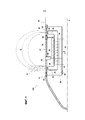
фиг.1 - фрагментарный вид в разрезе космического летательного аппарата, включающего в себя двигатель в соответствии с изобретением; иfigure 1 is a fragmentary sectional view of a spacecraft including an engine in accordance with the invention; and
фиг.2 - фрагментарный перспективный вид космического летательного аппарата, показанного на фиг.1.figure 2 is a fragmentary perspective view of the spacecraft shown in figure 1.
Подробное описание изобретенияDETAILED DESCRIPTION OF THE INVENTION
На фиг.1 и 2 показан космический летательный аппарат 100, в частности, спутник, включающий в себя двигатель 10 на эффекте Холла согласно изобретению.Figures 1 and 2 show a
Спутник представляет собой спутник, который должен находиться на орбите в земной атмосфере и оставаться на высоте в диапазоне от 100 километров (км) до 300 км.A satellite is a satellite that must be in orbit in the Earth’s atmosphere and remain at an altitude in the range of 100 kilometers (km) to 300 km.
Преимущественно, эта высота является относительно низкой, что позволяет некоторым частям оборудования (оборудованию связи, камерам и т.д.) иметь относительно маленький размер и, следовательно, массу. С другой стороны, на этой высоте земная атмосфера оказывает сопротивление движению спутника, которое является низким, но ненулевым. Поэтому необходимо компенсировать результирующую силу лобового сопротивления.Mostly, this height is relatively low, which allows some parts of the equipment (communication equipment, cameras, etc.) to have a relatively small size and, therefore, weight. On the other hand, at this altitude, the earth's atmosphere resists satellite motion, which is low but non-zero. Therefore, it is necessary to compensate for the resulting drag force.
Функция двигателя 10 состоит в том, чтобы обеспечить спутнику тягу, которая позволила бы поддерживать его эксплуатацию на требуемой высоте.The function of the
Она также служит для внесения изменений или корректировок орбиты.It also serves to make changes or adjustments to the orbit.
Преимущественно, двигатель согласно изобретению, такой как двигатель 10, когда он подключен к средству питания электрической энергией, такому как солнечные панели, может обеспечивать тягу, необходимую для поддержания спутника на высоте в течение длительных периодов времени.Advantageously, the engine according to the invention, such as
Спутник 100 размещается во внешнем защитном кожухе 20, который, как правило, имеет форму тела вращения относительно оси X. Двигатель 10 размещается внутри внешней стенки 22 кожуха 20, при этом основной участок стенки 22 имеет цилиндрическую внешнюю форму.The
В описанном варианте осуществления двигатель 10 имеет конструкцию, которая является осесимметричной относительно оси X. В данном контексте, термины "расположенный выше по потоку" и "расположенный ниже по потоку" определены относительно нормального направления движения спутника, и, следовательно, двигателя.In the described embodiment, the
Двигатель 10 имеет магнитный контур 30 и электрическую цепь 60.The
магнитный контур 30 выполнен с возможностью создания, как правило, радиального магнитного поля на расположенном в осевом направлении выше по потоку участке стенки 22 ("в осевом направлении" относительно оси X).the
Для этой цели он имеет множество идентичных отдельных магнитных контуров 32, которые размещаются осесимметричным способом относительно оси X.For this purpose, it has many identical individual
Каждый контур 32 содержит сердечник 34 из мягкого железа, имеющий осевое сечение, которое является U-образным. Сердечник 34 имеет длинный стержень 36, который продолжается параллельно оси X вблизи стенки 22 (в непосредственной близости от нее). Он также имеет два изогнутых сегмента 38, которые изогнуты по направлению к стенке 22 таким образом, чтобы концы сегментов размещались непосредственно под поверхностью стенки 22. Перед этими сегментами 38 кожух 20 имеет кольца 40 из немагнитного электроизоляционного материала для того, чтобы через него могло проходить магнитное поле. Например, кольца 40 можно выполнить из керамики, поликристаллического кубического углерода (более известного как алмаз) или оксида алюминия.Each
Каждый контур 32 также имеет катушку 46, которая образует соленоид, размещенный вокруг стержня 36.Each
Выводы катушек 46 контуров 32 подсоединены к выводам источника 44 напряжения. Источник напряжения выбирается таким образом, чтобы вокруг стенки можно было создать стабильное магнитное поле В под действием напряжения, приложенного к катушкам 46. Можно также использовать источник тока.The findings of the
Когда на катушки 46 подается напряжение из источника 44 напряжения, каждый магнитный контур 32 генерирует магнитное поле B. Это поле излучается контуром 32 снаружи спутника 100 в пространстве рядом со спутником. Силовые линии, которые образуются в этом случае, показаны на фиг.1. Как показано на этой фигуре, концы изогнутых сегментов 38 образуют, таким образом, магнитные полюса для контуров 32, то есть магнитный полюс 50, расположенный выше по потоку, и магнитный полюс 52 расположенный ниже по потоку.When voltage is supplied to the
Рядом с магнитным полюсом 50, расположенным выше по потоку, магнитное поле B сориентировано в направлении, которое по существу перпендикулярно к поверхности стенки 22.Near the
Как можно видеть на фигуре, расположенные выше по потоку магнитные полюса двух смежных отдельных магнитных контуров 32 сформированы таким образом, чтобы находиться близко друг к другу или даже по возможности в контакте друг с другом. То же самое относится и к расположенным ниже по потоку магнитным полюсам. Это позволяет магнитному контуру воспроизводить в любой осевой плоскости расположенный выше по потоку магнитный полюс и расположенный ниже по потоку магнитный полюс, которые генерируют магнитное поле. При этом магнитное поле B генерируется по существу равномерно по всей периферии стенки 22.As can be seen in the figure, the upstream magnetic poles of two adjacent separate
В другом варианте осуществления каждый контур 32 может быть по существу образован магнитом, имеющим по существу ту же самую форму, что и сердечник 34 из мягкого железа. В этом случае больше нет необходимости использовать катушки 46 и источник 44 напряжения, питающий их, чтобы генерировать магнитное поле В вокруг двигателя 10.In another embodiment, each
Двигатель 10 также имеет электрическую цепь 60. Эта цепь содержит анод 62, первый катод 64, второй катод 66, третий катод 67 (или дополнительный катод) и источник 68 напряжения, соединяющий анод 62 с первым, вторым и третьим катодами 64, 66 и 67.The
Анод 62 выполнен из материала, который является электропроводным и предпочтительно немагнитным, такого, например, как графит, нержавеющая сталь или фактически какой-либо другой металл.
Катоды предназначены для испускания электронов и могут быть изготовлены из любого из следующих материалов: гексаборид лантана (LaB6), вольфрам, пропитанный барием (WBa) и т.д.The cathodes are designed to emit electrons and can be made of any of the following materials: lanthanum hexaboride (LaB6), tungsten impregnated with barium (WBa), etc.
Отсутствует необходимость в том, чтобы катоды имели кольцеобразную форму, при этом они с таким же успехом могут быть точечными катодами (полыми катодами). В частности, магнитное топологическое расстояние зависит от силовых линий, а не от физических расстояний. Если катод представляет собой точечный катод (полый катод), кольцо 64 не имеет определенной функции в электрической цепи; при этом можно просто использовать электропроводный материал на поверхности во избежание накопления электростатических зарядов, как для стенки 22.There is no need for the cathodes to have an annular shape, while they can equally well be point cathodes (hollow cathodes). In particular, the magnetic topological distance depends on the lines of force, and not on physical distances. If the cathode is a point cathode (hollow cathode),
Анод 62 расположен в осевом направлении выше по потоку относительно магнитного полюса 50, расположенного выше по потоку. Первый катод 64 расположен ниже по потоку относительно магнитного полюса 50, но поблизости от него (и предпочтительно в непосредственной близости от него) и, таким образом, на некотором расстоянии выше по потоку от расположенного ниже по потоку магнитного полюса 52.
Второй катод 66 расположен между магнитным полюсом 50, расположенным выше по потоку, и магнитным полюсом 52, расположенным ниже по потоку.The
Таким образом, он располагается ниже по потоку относительно магнитного полюса 50 и выше по потоку относительно магнитного полюса 52.Thus, it is located downstream of the
Третий катод 67 расположен ниже по потоку относительно магнитного полюса 52.The
Каждый из катодов 66 и 67 также располагается вблизи от магнитного полюса 52, и таким образом на некотором расстоянии ниже по потоку относительно первого катода 64.Each of the
Хотя цепь 60 имеет три катода 64, 66 и 67, в других вариантах осуществления можно предусмотреть только один катод или фактически предусмотреть только два катода. Положение одного катода или положения двух катодов можно свободно выбрать среди положений катодов 64, 66 и 67.Although
Анод 62 и первый, второй и третий катоды 64, 66 и 67 имеют кольцеобразную форму. Каждое из этих колец продолжается по всей окружности стенки 22, как правило, в плоскости, перпендикулярной оси X (или более точно между двумя плоскостями, расположенными перпендикулярно оси X). Каждое из этих колец расположено заподлицо с поверхностью стенки 22 и, таким образом, образует участок стенки.The
Когда напряжение, подаваемое из источника 68 напряжения, прикладывается между анодом 62 и катодами 64, 66 и 67, в пространстве снаружи спутника вокруг стенки 22 между анодом 62 и первым катодом 64 образуется электрическое поле E. Это поле ориентировано по существу в направлении, параллельном оси X.When a voltage supplied from the
С другой стороны, электрическое поле E вблизи расположенного ниже по потоку магнитного полюса 52 является чрезвычайно низким. Следовательно, сила, выработанная двигателем 10, создается вблизи расположенного выше по потоку магнитного полюса 50, в то время как при отсутствии электрического поля E, практически нет никакой противодействующей силы, вырабатываемой вблизи расположенного ниже по потоку магнитного полюса 52.On the other hand, the electric field E in the vicinity of the downstream
Наконец, следует заметить, что источник 68 напряжения является управляемым (хотя, это не показано на фигурах): можно изменить полярность электрического напряжения для того, чтобы изменить на противоположную тягу, возникающую от двигателя.Finally, it should be noted that the
В частности, два его полюса могут по команде меняться местами, чтобы при необходимости изменить на противоположное напряжение, прикладываемое между анодом и первым и вторым катодами. Это изменение полярности служит для изменения направления на противоположное силы, прикладываемой двигателем 10, например, для того, чтобы осуществить торможение спутника 100 во время возвращения в плотные слои атмосферы.In particular, its two poles can be interchanged at the command to change, if necessary, the opposite voltage applied between the anode and the first and second cathodes. This change in polarity serves to reverse the direction of the force exerted by the
Назначения анода и катода являются взаимозаменяемыми, если они имеют особенность, которая делает это возможным.The anode and cathode assignments are interchangeable if they have a feature that makes this possible.
В другом варианте осуществления катод, расположенный выше по потоку относительно полюса 50, и анод, расположенный ниже по потоку относительно него, можно снабдить источником 68 напряжения, подключаемым к нему в режиме изменения направления тяги на противоположное.In another embodiment, the cathode located upstream relative to the
Затем этот катод и этот анод используются в режиме изменения направления тяги на противоположное вместо и в замен анода 62 и катодов 64, 66 и 67.Then this cathode and this anode are used in the opposite direction of the thrust direction instead of and in replacement of the
Двигатель 10 действует надлежащим образом.The
Как правило, между катодами 64, 66 и 67, расположенными ниже по потоку относительно анода 62, расположенного выше по потоку, устанавливается напряжение порядка 150-800 Вольт (В). Затем катоды 64, 66 и 67 начинают испускать электроны. Большая часть этих электронов захватывается магнитной оболочкой, образованной магнитным полем, создаваемым магнитным контуром 30 и адаптированным к желаемым характеристикам, и которое обычно составляет порядка 100-300 Гаусс. Таким образом, электроны, захваченные этой магнитной оболочкой, образуют виртуальную катодную сетку 70. Тем не менее, некоторые электроны с высокой энергией (обычно от 10 электрон-вольт (эВ) до 40 эВ) вылетают из магнитной оболочки 70 и попадают на анод 62.As a rule, between the
Поскольку спутник 100 движется относительно атмосферы, частицы всегда проникают в виртуальную катодную сетку 70. Соударение, возникающее между электронами, удерживаемыми в сетке, и атомами этих частиц приводят к ионизации атомов. Затем под действием электрического поля E, выработанного электрической цепью 60, ионизированные частицы ускоряются по направлению к задней части спутника. Таким образом, двигатель 10 вырабатывает струю плазмы, которая выбрасывается с чрезвычайно высокой скоростью в направлении X по направлению к задней части спутника, расположенного ниже по потоку относительно стенки 22. По причинам симметрии вырабатываемая тяга по существу совпадает с центральной осью X.As the
В зависимости от полярности напряжения, подаваемого из источника 68 напряжения, сила, создаваемая двигателем 10, может быть направлена либо в одном направлении, либо в противоположном направлении вдоль оси X.Depending on the polarity of the voltage supplied from the
Когда двигатель 10 находится в работе, второй и третий катоды 66 и 67 подают электроны в частицы, выпущенные ниже по потоку спутника 100, тем самым обеспечивая их электрическую нейтральность.When the
В частности, использование второго катода является необязательным. В основном третий катод 67 расположен ниже по потоку относительно магнитного полюса 52, расположенного ниже по потоку, который обеспечивает подачу электронов, необходимых для нейтрализации частиц, ускоренных двигателем 10.In particular, the use of a second cathode is optional. Basically, the
Преимущественно, двигатель согласно изобретению не требует подачи выхлопного газа, в отличие от большинства двигателей на эффекте Холла.Advantageously, the engine according to the invention does not require an exhaust gas supply, unlike most Hall effect engines.
Кроме того, его размещение на внешней стенке спутника освобождает большое количество пространства внутри спутника, тем самым делая возможным установку в нем большой полезной нагрузки.In addition, its placement on the outer wall of the satellite frees up a large amount of space inside the satellite, thereby making it possible to install a large payload in it.
Наконец, следует заметить, что двигатель может быть размещен неосесимметричным образом, но все еще оставаться в пределах объема изобретения. В частности, катушки 46 не обязательно должны быть идентичными. Например, они могут быть расположены таким образом, чтобы магнитное поле было более интенсивно с одной стороны стенки, чем с противоположной стенки. При таких обстоятельствах тяга, создаваемая двигателем, больше не направлена вдоль оси стенки, а ориентируется с небольшим смещением относительно ее.Finally, it should be noted that the engine can be positioned in an axisymmetric manner, but still remain within the scope of the invention. In particular, coils 46 need not be identical. For example, they can be arranged so that the magnetic field is more intense on one side of the wall than on the opposite wall. Under such circumstances, the thrust created by the engine is no longer directed along the axis of the wall, but is oriented with a slight displacement relative to it.
Claims (15)
Applications Claiming Priority (3)
| Application Number | Priority Date | Filing Date | Title |
|---|---|---|---|
| FR1550745 | 2015-01-30 | ||
| FR1550745A FR3032325A1 (en) | 2015-01-30 | 2015-01-30 | HALL EFFECTOR AND SPACE ENGINE COMPRISING SUCH A PROPELLER |
| PCT/FR2016/050186 WO2016120570A1 (en) | 2015-01-30 | 2016-01-28 | Hall effect thruster, and spacecraft including such a thruster |
Publications (3)
| Publication Number | Publication Date |
|---|---|
| RU2017130327A RU2017130327A (en) | 2019-02-28 |
| RU2017130327A3 RU2017130327A3 (en) | 2019-08-15 |
| RU2703870C2 true RU2703870C2 (en) | 2019-10-22 |
Family
ID=53404652
Family Applications (1)
| Application Number | Title | Priority Date | Filing Date |
|---|---|---|---|
| RU2017130327A RU2703870C2 (en) | 2015-01-30 | 2016-01-28 | Engine on hall effect and space vehicle, including such engine |
Country Status (8)
| Country | Link |
|---|---|
| US (1) | US10131453B2 (en) |
| EP (1) | EP3250822B1 (en) |
| JP (1) | JP6693967B2 (en) |
| CN (1) | CN107207100B (en) |
| FR (1) | FR3032325A1 (en) |
| IL (1) | IL253659B (en) |
| RU (1) | RU2703870C2 (en) |
| WO (1) | WO2016120570A1 (en) |
Families Citing this family (2)
| Publication number | Priority date | Publication date | Assignee | Title |
|---|---|---|---|---|
| CN107939625B (en) * | 2017-11-13 | 2019-04-05 | 中国人民解放军国防科技大学 | Reflection type laser-electromagnetic field coupling thruster |
| CN115681062B (en) * | 2023-01-03 | 2023-06-02 | 国科大杭州高等研究院 | Mixed working mode Hall propulsion system and spacecraft with same |
Citations (4)
| Publication number | Priority date | Publication date | Assignee | Title |
|---|---|---|---|---|
| RU2088802C1 (en) * | 1995-12-09 | 1997-08-27 | Исследовательский центр им.М.В.Келдыша | Hall motor |
| US20030046921A1 (en) * | 2001-06-21 | 2003-03-13 | Vlad Hruby | Air breathing electrically powered hall effect thruster |
| US20080223017A1 (en) * | 2007-03-14 | 2008-09-18 | Japan Aerospace Exploration Agency | Hall-type electric propulsion |
| WO2013076409A1 (en) * | 2011-11-22 | 2013-05-30 | Snecma | Hall-effect thruster |
Family Cites Families (8)
| Publication number | Priority date | Publication date | Assignee | Title |
|---|---|---|---|---|
| US3151259A (en) * | 1959-08-18 | 1964-09-29 | Gen Electric | Plasma accelerator system |
| RU1796777C (en) * | 1991-06-28 | 1993-02-23 | Опытное конструкторское бюро "Факел" | Stationary plasma engine |
| RU2092983C1 (en) * | 1996-04-01 | 1997-10-10 | Исследовательский центр им.М.В.Келдыша | Plasma accelerator |
| WO1997037127A1 (en) * | 1996-04-01 | 1997-10-09 | International Scientific Products | A hall effect plasma accelerator |
| US7459858B2 (en) * | 2004-12-13 | 2008-12-02 | Busek Company, Inc. | Hall thruster with shared magnetic structure |
| FR2911956B1 (en) * | 2007-01-29 | 2009-05-08 | Hispano Suiza Sa | DEVICE FOR MEASURING THE POSITION OF A PISTON IN A CYLINDER, A SET OF A CYLINDER, A PISTON AND A SUCH DEVICE AND AN AIRCRAFT ENGINE COMPRISING SUCH AN ASSEMBLY |
| FR2959534B1 (en) * | 2010-04-29 | 2012-07-13 | Snecma | HALL EFFECT ENGINE WITH REGULATION OF THE TEMPERATURE OF THE CATHODE HEATING DEVICE |
| FR2986577B1 (en) * | 2012-02-06 | 2016-05-20 | Snecma | HALL EFFECTOR |
-
2015
- 2015-01-30 FR FR1550745A patent/FR3032325A1/en active Pending
-
2016
- 2016-01-28 WO PCT/FR2016/050186 patent/WO2016120570A1/en active Application Filing
- 2016-01-28 CN CN201680008135.XA patent/CN107207100B/en active Active
- 2016-01-28 US US15/547,360 patent/US10131453B2/en active Active
- 2016-01-28 EP EP16707851.8A patent/EP3250822B1/en active Active
- 2016-01-28 JP JP2017540140A patent/JP6693967B2/en active Active
- 2016-01-28 RU RU2017130327A patent/RU2703870C2/en active
-
2017
- 2017-07-25 IL IL253659A patent/IL253659B/en active IP Right Grant
Patent Citations (4)
| Publication number | Priority date | Publication date | Assignee | Title |
|---|---|---|---|---|
| RU2088802C1 (en) * | 1995-12-09 | 1997-08-27 | Исследовательский центр им.М.В.Келдыша | Hall motor |
| US20030046921A1 (en) * | 2001-06-21 | 2003-03-13 | Vlad Hruby | Air breathing electrically powered hall effect thruster |
| US20080223017A1 (en) * | 2007-03-14 | 2008-09-18 | Japan Aerospace Exploration Agency | Hall-type electric propulsion |
| WO2013076409A1 (en) * | 2011-11-22 | 2013-05-30 | Snecma | Hall-effect thruster |
Non-Patent Citations (1)
| Title |
|---|
| A1. * |
Also Published As
| Publication number | Publication date |
|---|---|
| WO2016120570A1 (en) | 2016-08-04 |
| RU2017130327A3 (en) | 2019-08-15 |
| US20180022475A1 (en) | 2018-01-25 |
| FR3032325A1 (en) | 2016-08-05 |
| CN107207100A (en) | 2017-09-26 |
| EP3250822A1 (en) | 2017-12-06 |
| IL253659A0 (en) | 2017-09-28 |
| JP2018503774A (en) | 2018-02-08 |
| US10131453B2 (en) | 2018-11-20 |
| CN107207100B (en) | 2020-05-19 |
| JP6693967B2 (en) | 2020-05-13 |
| RU2017130327A (en) | 2019-02-28 |
| EP3250822B1 (en) | 2019-03-13 |
| IL253659B (en) | 2021-01-31 |
Similar Documents
| Publication | Publication Date | Title |
|---|---|---|
| JP6645987B2 (en) | Engine for spacecraft and spacecraft equipped with the above-mentioned engine | |
| JP6756814B2 (en) | Hall effect propulsion machine that can be used at high altitudes | |
| JP3609407B2 (en) | Short plasma accelerator with closed electron drift | |
| US5847493A (en) | Hall effect plasma accelerator | |
| US5241244A (en) | Cyclotron resonance ion engine | |
| EP3369294B1 (en) | Plasma accelerator with modulated thrust and space born vehicle with the same | |
| US10539122B2 (en) | Plasma accelerating apparatus and plasma accelerating method | |
| CN104583589B (en) | Ion accelerator | |
| UA114495C2 (en) | Hall-effect thruster | |
| JP6935284B2 (en) | Hall thruster | |
| JP6360903B2 (en) | Ground system and method for testing reactive thrusters | |
| CN1219279A (en) | Hall effect plasma thruster | |
| RU2703870C2 (en) | Engine on hall effect and space vehicle, including such engine | |
| US10961989B2 (en) | Ion thruster with external plasma discharge | |
| RU158759U1 (en) | ION-PLASMA ENGINE | |
| CN115898802B (en) | Hall thruster, space device comprising same and use method thereof | |
| JP2018503774A5 (en) | ||
| CN115681052B (en) | Hall thruster, equipment with same and use method of Hall thruster | |
| RU2474984C1 (en) | Plasma accelerator with closed electron drift | |
| RU139030U1 (en) | ION-PLASMA ENGINE | |
| RU2614906C1 (en) | Direct flow electric propulsion engine | |
| RU208147U1 (en) | Ionic micromotor | |
| RU2565646C1 (en) | Ionic engine | |
| RU159636U1 (en) | ION-PLASMA ENGINE | |
| JP2007280782A (en) | Ion source |