JP6693967B2 - Hall effect thruster - Google Patents
Hall effect thruster Download PDFInfo
- Publication number
- JP6693967B2 JP6693967B2 JP2017540140A JP2017540140A JP6693967B2 JP 6693967 B2 JP6693967 B2 JP 6693967B2 JP 2017540140 A JP2017540140 A JP 2017540140A JP 2017540140 A JP2017540140 A JP 2017540140A JP 6693967 B2 JP6693967 B2 JP 6693967B2
- Authority
- JP
- Japan
- Prior art keywords
- hall effect
- magnetic
- thruster
- wall
- cathode
- Prior art date
- Legal status (The legal status is an assumption and is not a legal conclusion. Google has not performed a legal analysis and makes no representation as to the accuracy of the status listed.)
- Active
Links
- 230000005355 Hall effect Effects 0.000 title claims description 24
- 238000011144 upstream manufacturing Methods 0.000 claims description 24
- 230000005684 electric field Effects 0.000 claims description 9
- 230000002441 reversible effect Effects 0.000 claims description 4
- 230000001151 other effect Effects 0.000 claims 1
- 239000002245 particle Substances 0.000 description 10
- 238000005452 bending Methods 0.000 description 3
- OKTJSMMVPCPJKN-UHFFFAOYSA-N Carbon Chemical compound [C] OKTJSMMVPCPJKN-UHFFFAOYSA-N 0.000 description 2
- XEEYBQQBJWHFJM-UHFFFAOYSA-N Iron Chemical group [Fe] XEEYBQQBJWHFJM-UHFFFAOYSA-N 0.000 description 2
- 230000000694 effects Effects 0.000 description 2
- 230000007935 neutral effect Effects 0.000 description 2
- 230000036961 partial effect Effects 0.000 description 2
- 230000001133 acceleration Effects 0.000 description 1
- PNEYBMLMFCGWSK-UHFFFAOYSA-N aluminium oxide Inorganic materials [O-2].[O-2].[O-2].[Al+3].[Al+3] PNEYBMLMFCGWSK-UHFFFAOYSA-N 0.000 description 1
- 229910052799 carbon Inorganic materials 0.000 description 1
- 239000000919 ceramic Substances 0.000 description 1
- 239000004020 conductor Substances 0.000 description 1
- 238000012937 correction Methods 0.000 description 1
- 229910003460 diamond Inorganic materials 0.000 description 1
- 239000010432 diamond Substances 0.000 description 1
- 239000012777 electrically insulating material Substances 0.000 description 1
- 230000005611 electricity Effects 0.000 description 1
- 229910002804 graphite Inorganic materials 0.000 description 1
- 239000010439 graphite Substances 0.000 description 1
- 229910052746 lanthanum Inorganic materials 0.000 description 1
- FZLIPJUXYLNCLC-UHFFFAOYSA-N lanthanum atom Chemical compound [La] FZLIPJUXYLNCLC-UHFFFAOYSA-N 0.000 description 1
- 230000000670 limiting effect Effects 0.000 description 1
- 239000000696 magnetic material Substances 0.000 description 1
- 239000000463 material Substances 0.000 description 1
- 229910052751 metal Inorganic materials 0.000 description 1
- 239000002184 metal Substances 0.000 description 1
- 239000003380 propellant Substances 0.000 description 1
- 230000001681 protective effect Effects 0.000 description 1
- 229910001220 stainless steel Inorganic materials 0.000 description 1
- 239000010935 stainless steel Substances 0.000 description 1
- 230000003068 static effect Effects 0.000 description 1
- 238000010408 sweeping Methods 0.000 description 1
- WFKWXMTUELFFGS-UHFFFAOYSA-N tungsten Chemical compound [W] WFKWXMTUELFFGS-UHFFFAOYSA-N 0.000 description 1
- 229910052721 tungsten Inorganic materials 0.000 description 1
- 239000010937 tungsten Substances 0.000 description 1
Images

Classifications
-
- B—PERFORMING OPERATIONS; TRANSPORTING
- B64—AIRCRAFT; AVIATION; COSMONAUTICS
- B64G—COSMONAUTICS; VEHICLES OR EQUIPMENT THEREFOR
- B64G1/00—Cosmonautic vehicles
- B64G1/22—Parts of, or equipment specially adapted for fitting in or to, cosmonautic vehicles
- B64G1/40—Arrangements or adaptations of propulsion systems
- B64G1/405—Ion or plasma engines
-
- F—MECHANICAL ENGINEERING; LIGHTING; HEATING; WEAPONS; BLASTING
- F03—MACHINES OR ENGINES FOR LIQUIDS; WIND, SPRING, OR WEIGHT MOTORS; PRODUCING MECHANICAL POWER OR A REACTIVE PROPULSIVE THRUST, NOT OTHERWISE PROVIDED FOR
- F03H—PRODUCING A REACTIVE PROPULSIVE THRUST, NOT OTHERWISE PROVIDED FOR
- F03H1/00—Using plasma to produce a reactive propulsive thrust
- F03H1/0006—Details applicable to different types of plasma thrusters
- F03H1/0012—Means for supplying the propellant
-
- F—MECHANICAL ENGINEERING; LIGHTING; HEATING; WEAPONS; BLASTING
- F03—MACHINES OR ENGINES FOR LIQUIDS; WIND, SPRING, OR WEIGHT MOTORS; PRODUCING MECHANICAL POWER OR A REACTIVE PROPULSIVE THRUST, NOT OTHERWISE PROVIDED FOR
- F03H—PRODUCING A REACTIVE PROPULSIVE THRUST, NOT OTHERWISE PROVIDED FOR
- F03H1/00—Using plasma to produce a reactive propulsive thrust
- F03H1/0037—Electrostatic ion thrusters
- F03H1/0062—Electrostatic ion thrusters grid-less with an applied magnetic field
- F03H1/0068—Electrostatic ion thrusters grid-less with an applied magnetic field with a central channel, e.g. end-Hall type
-
- H—ELECTRICITY
- H05—ELECTRIC TECHNIQUES NOT OTHERWISE PROVIDED FOR
- H05H—PLASMA TECHNIQUE; PRODUCTION OF ACCELERATED ELECTRICALLY-CHARGED PARTICLES OR OF NEUTRONS; PRODUCTION OR ACCELERATION OF NEUTRAL MOLECULAR OR ATOMIC BEAMS
- H05H1/00—Generating plasma; Handling plasma
- H05H1/54—Plasma accelerators
Description
本発明は、空気吸入式ホール効果スラスタの分野に関する。 The present invention relates to the field of air-breathing Hall effect thrusters.
通常、空気吸入式ホール効果スラスタは、
作動時にスラスタによって粒子を収集し、加速し、噴出するためのノズルと、
アノードと、アノードの下流のカソードと、カソードを介して電子を放出しかつアノードを介して電子を引き付けるための電圧源とを備える電気回路と、
軸線方向にアノードから下流にノズルにおいて磁場を生成するための磁気回路であって、磁場が推進軸線に対して実質的に放射状の方向を向く、磁気回路とを備える。
Normally, air-breathing Hall effect thrusters
A nozzle for collecting, accelerating and ejecting particles by a thruster during operation,
An anode, the anode of the downstream cathode, and an electric circuit comprising a voltage source for attracting electrons through the release vital anode electrons through the cathode,
A magnetic circuit for producing a magnetic field in the nozzle axially downstream from the anode , wherein the magnetic field is oriented substantially radially with respect to the propulsion axis.
例えば、上記のスラスタは、ある特許文献において説明される(例えば、特許文献1参照。)。 For example, the above thruster is described in a certain patent document (for example, refer to Patent Document 1).
実際には、ノズルは、磁気回路が放射状磁場を生成できるようにするために概ね環状である。したがって、ノズルは、内側壁と外側壁とを備え、粒子は、2つの壁の間を通過する。 In practice, the nozzle is generally annular to allow the magnetic circuit to produce a radial magnetic field. The nozzle thus comprises an inner wall and an outer wall, the particles passing between the two walls.
特に、このようなノズルのため、このようなスラスタを含む宇宙船の内部空間の特に大きな部分が占められてしまう。 In particular, such nozzles occupy a particularly large portion of the interior space of the spacecraft containing such thrusters.
したがって、本発明の目的は、設置されたとき宇宙船において占める空間がより小さいホール効果スラスタを提供することである。 Accordingly, it is an object of the present invention to provide a Hall effect thruster that, when installed, occupies less space in a spacecraft.
この目的は、推進軸線に沿って推力を展開するためのホール効果スラスタであって、ホール効果スラスタは、
磁場を生成するための磁気回路と、
アノードと、第1カソードと、少なくとも第1カソードを介して電子を放出しかつアノードを介して電子を引き付けるための電圧源と、を備える電気回路とを備え、
スラスタは、
推進軸線の周りに形成された円筒形壁内部に配置され、
磁気回路及び電気回路が、壁の周りに磁場及び電場を生成するように配列され、かつ
推進軸線に平行でかつ壁に直交する全ての断面において、
磁気回路が、実質的に壁の表面に配置され相互に離間する、上流磁極と下流磁極とを有し、かつ、
アノード及び第1カソードが上流磁極の両側に配置される、ことを特徴とする、ホール効果スラスタによって達成される。
The purpose is a Hall effect thruster for deploying thrust along a propulsion axis, which is
A magnetic circuit for generating a magnetic field,
An electric circuit comprising: an anode , a first cathode, and a voltage source for emitting electrons through at least the first cathode and for attracting electrons through the anode ,
Thruster
Located inside a cylindrical wall formed around the propulsion axis,
Magnetic and electrical circuits are arranged to generate magnetic and electric fields around the wall, and in all cross sections parallel to the propulsion axis and orthogonal to the wall,
A magnetic circuit having an upstream magnetic pole and a downstream magnetic pole disposed substantially on the surface of the wall and spaced apart from each other, and
Achieved by a Hall effect thruster, characterized in that the anode and the first cathode are arranged on opposite sides of the upstream pole.
上述の壁は、当然、スラスタが取り付けられる宇宙船の外部壁である。 The wall described above is, of course, the outer wall of the spacecraft to which the thruster is attached.
壁は、通常、軸対称の壁である。 The wall is usually an axisymmetric wall.
特に、壁は、円筒形壁とすることができる。「円筒形壁」は、本明細書において、閉鎖輪郭の周りにおいて定方向の「ゼネレータ」ラインを掃引することによって生成される表面を持つ壁を意味する。 In particular, the wall can be a cylindrical wall. By "cylindrical wall" herein is meant a wall having a surface created by sweeping a directional "generator" line around a closed contour.
スラスタによって展開された推力は、概ね、壁の対称軸に沿った方向を向く。 The thrust developed by the thruster is generally oriented along the axis of symmetry of the wall.
但し、一つの実施形態において、磁気回路及び/又は電気回路は、壁の周りに非軸対称磁場及び/又は電場(B及び/又はE)を生成するように配列される。スラスタによって生成された推力は、その後スラスタの軸線(円筒形壁によって画定される)に対して側方成分を示す。したがって、円筒形壁の軸線方向に対して多少傾斜する方向を向く。 However, in one embodiment, the magnetic and / or electrical circuits are arranged to generate a non-axisymmetric magnetic field and / or electric field (B and / or E) around the wall. The thrust produced by the thruster then exhibits a lateral component with respect to the thruster axis (defined by the cylindrical wall). Therefore, it faces a direction slightly inclined with respect to the axial direction of the cylindrical wall.
閉鎖輪郭は、円形、楕円形又は長円形とすることができ、例えば、競技トラックなどの形状を持つことができる。 The closed contour can be circular, elliptical or oval, for example having the shape of a competition track.
本発明は、したがって、ノズル内ではなく、したがって宇宙船内ではなく宇宙船外部で粒子加速を構成することによって、ホール効果スラスタの設計を完全に逆転する。 The present invention therefore completely reverses the design of Hall effect thrusters by configuring particle acceleration outside the spacecraft, not within the nozzle and thus within the spacecraft.
本発明によれば、磁気回路によって発生した磁場は、宇宙船の円周全体で電子を捕捉する。但し、磁場は、円周の周りの位置の関数として変動する強さを持つことができる。 According to the present invention, the magnetic field generated by the magnetic circuit traps electrons throughout the circumference of the spacecraft. However, the magnetic field can have a strength that varies as a function of position around the circumference.
磁気回路は、概略的に、磁場が上流磁極の隣の壁の表面に概ね直交する方向を向くように、配列される。 The magnetic circuit is generally arranged such that the magnetic field is oriented generally orthogonal to the surface of the wall next to the upstream pole.
壁と磁力線との間の角度は、90°から僅かに逸れることができる。特に、75°〜105°の範囲にあれば充分である。 The angle between the wall and the magnetic field lines can deviate slightly from 90 °. In particular, the range of 75 ° to 105 ° is sufficient.
本発明によれば、電気回路及び磁気回路は、このように、先行技術の設計のスラスタと比べて完全に修正される。但し、ホール効果エンジンの作動原理は、先行技術のホール効果スラスタの作動原理と実質的に同じままである。 According to the invention, the electric and magnetic circuits are thus completely modified compared to the thrusters of the prior art design. However, the operating principle of the Hall effect engine remains substantially the same as that of prior art Hall effect thrusters.
一つの実施形態において、電気回路は、下流磁極から軸線方向に下流に配列された少なくとも一つの別のカソードを含む。この別のカソードは、宇宙船から下流に放出された粒子に電子を供給して、粒子を電気的に中性にするのに役立つ。 In one embodiment, the electrical circuit includes at least one further cathode arranged axially downstream from the downstream pole. This other cathode serves to supply electrons to the particles emitted downstream from the spacecraft, making them electrically neutral.
本発明は、以上に規定するように少なくとも一つのホール効果スラスタを組み込む宇宙船も提供する。 The invention also provides a spacecraft incorporating at least one Hall effect thruster as defined above.
本発明は、非限定的例として下に示す実施形態の詳細な説明を読むことによって、充分に理解できかつその利点が明らかになる。説明は、下記の図面を参照する。 The invention will be fully understood and its advantages will become apparent upon reading the detailed description of the embodiments given below by way of non-limiting example. The description refers to the following drawings.
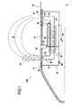
図1及び2は、本発明のホール効果スラスタ10を含む宇宙船100、特に人工衛星を示す。
1 and 2 show a
人工衛星は、地球の大気圏の軌道を回って100キロメートル(km)〜300kmの高度を維持する衛星である。 An artificial satellite is a satellite that orbits the earth's atmosphere and maintains an altitude of 100 kilometers (km) to 300 km.
有利なことには、この高度は比較的低く、設備の一部のピース(通信設備、カメラなど)を比較的小さいサイズしたがって比較的小さい質量にできる。逆に、この高度において、地球の大気圏は、低いがゼロではない衛星の通過に対する抵抗に対抗する。したがって、その結果生じるドラグを補正する必要がある。 Advantageously, this altitude is relatively low, allowing some pieces of equipment (communication equipment, cameras, etc.) to have a relatively small size and thus a relatively small mass. Conversely, at this altitude, the Earth's atmosphere counters the resistance to passage of low but nonzero satellites. Therefore, it is necessary to correct the resulting drag.
スラスタ10の機能は、人工衛星に推力を与えて、所望の高度で作動を維持できるようにすることである。
The function of the
スラスタは、また軌道変更または修正を行うのにも役立つ。 Thrusters also serve to make orbit changes or corrections.
有利なことに、スラスタ10などの本発明のスラスタは、ソーラーパネルなどの電力供給手段に結合されたとき、人工衛星を所定高度に長期間維持するために必要な推力を与えることができる。
Advantageously, the thruster of the present invention, such as
人工衛星100は、概ね軸線Xの周りの回転体の形式である外側保護ケーシング20の中に配置される。スラスタ10は、ケーシング20の外部壁22内部に配置される。壁22の主要部分は円筒形の外部形状を持つ。
The
説明する実施形態において、スラスタ10は、軸線Xの周りで軸対称である構造を有する。この文脈において、「上流」及び「下流」は、人工衛星したがってスラスタの正常行程方向に対して規定される。
In the illustrated embodiment, the
スラスタ10は、磁気回路30と電気回路60とを有する。
The
磁気回路30は、壁22の軸線方向に(軸線Xに対して「軸線方向」)上流の部分に概ね放射状の磁場を生成するように配列される。
The
このために、軸線Xの周りで軸対称に配列される複数の同一の個別の磁気回路32を有する。
To this end, it has a plurality of identical individual
各回路32は、U字形の軸線断面を有する軟鉄芯34を備える。芯34は、壁22に近接して軸線Xに平行に延びる長いロッド36を有する。また、屈曲区分の端部が壁22の表面のすぐ下に配列されるように、壁22へ向かって曲がる屈曲区分38も有する。これらの区分38に対面して、ケーシング20は、磁場が通過できるようにするために、非磁気、電気絶縁材料のリング40を有する。リング40は、例えばセラミック、多結晶立方晶炭素(ダイアモンドとして知られる)又はアルミナで作ることができる。
Each
各回路32は、ロッド36の周りに配列されたソレノイドを形成するコイル46も有する。
Each
回路32のコイル36の端末は、電圧源44の端末に接続される。電圧源は、コイル46へ加えられた電圧の効果を受けて、壁の周りに安定した磁場Bを生成できるように選択される。また、電流源を使用することも可能である。
The end of the
電圧源44によってコイル46へ電圧が加えられたとき、各磁気回路32は、磁場Bを生成する。この磁場は、回路32によって人工衛星の傍らの空間において衛星100の外部へ放射される。形成される磁力線を図1に示す。この図に示すように、屈曲区分38の端部は、回路32のための磁極、即ち上流磁極50及び下流磁極52を形成する。
Each
上流磁極50の隣において、磁場Bは壁22の表面に対して実質的に直交する方向を向く。
Next to the
図から分かるように、2つの隣り合う別個の磁気回路32の上流磁極は、相互に接近するように又は可能であれば接触するように形成される。同じことが下流磁極にも言える。これによって、磁気回路は、任意の軸平面において上流磁極と下流磁極を持つことができ、磁極は磁場を生成する。これによって、磁場Bは、壁22の周縁全体において実質的に均等に生成される。
As can be seen, the upstream poles of two adjacent discrete
別の実施形態において、各回路32は、基本的に、実質的に軟鉄芯34と同じ形状を有する磁石によって構成できる。この場合、スラスタ10の周りに磁場Bを生成するためにコイル46及びこれに動力を供給する電圧源44を設置する必要がない。
In another embodiment, each
スラスタ10は、電気回路60も有する。この回路は、アノード62と、第1カソード64と、第2カソード66と、第3カソード67(又は付加的カソード)と、アノード62を第1、第2に及び第3カソード64、66及び67に接続する電圧源68と、を備える。
The
アノード62は、導電性でかつ好ましくは非磁気性の材料例えばグラファイト、ステンレス鋼又は他の金属で作られる。
The
カソードは、電子を放出するように設計され、六ほう化ランタン(LaB6)、バリウム含浸タングステン(WBa)の任意の一つの材料で作ることができる。 The cathode is designed to emit electrons and can be made of any one material of lanthanum hexaboride (LaB 6 ), barium-impregnated tungsten (WBa).
カソードはリング形である必要はなく、スポットカソード(中空カソード)でもよい。具体的には、磁気位相距離(magnetic topological distance)は、物理的距離ではなく力線によって決まる。カソードがスポットカソード(中空カソード)である場合、電気回路においてリング64は明白な役割を持たない。即ち、壁22に静電気が蓄積するのを避けるために表面において単に導電体を使用することが可能である。
The cathode does not have to be ring-shaped and may be a spot cathode (hollow cathode ). Specifically, the magnetic topological distance is determined by the lines of force rather than the physical distance. If the cathode is a spot cathode (hollow cathode ), the
アノード62は、上流磁極50から軸線方向に上流に配置される。第1カソード64は、上流磁極50から下流に但しこれに近接して(望ましくはそのすぐ隣に)したがって下流磁極52から上流に所定距離に配置される。
The
第2カソード66は、上流磁極50と下流磁極52との間に配置される。
The
したがって、第2カソードは、上流磁極50の下流でかつ下流磁極52の上流にある。
Therefore, the second cathode is downstream of the upstream
第3カソード67は、下流磁極52の下流に配置される。
The
カソード66及び67の各々は、下流磁極52に近接して、したがって、第1カソードから下流に所定距離に配置される。
Each of the
回路60は、3つのカソード64、66及び67を持つが、他の実施形態において、一つのカソードしか設置しないことが可能であり、2つのカソードを設置することも可能である。一つのカソードの位置又は2つのカソードの位置は、カソード64、66及び67の位置から自由に選択できる。
アノード62及び第1、第2及び第3カソード64、66及び67は、全てリング形である。これらのリングは、各々、軸線Xに対して概ね直交する平面(又はより正確には軸線に直交する2つの近接する平面の間)において壁22の円周全体に延びる。3つのリングの各々は、壁22の表面と同一平面に在り、壁の一部分を構成する。
The
アノード62とカソード64、66及び67との間で電圧源68によって電圧が加えられるとき、電場Eは、人工衛星の外部空間において、壁22の周りのアノード62と第1カソード64との間に形成される。電場は、軸線Xに対して実質的に平行の方向を向く。
When a voltage is applied by the
逆に、電場Eは、下流磁極52の近隣においては極めて低い。したがって、スラスタ10によって生成される力は、上流磁極50に近接して生成され、電場Eがないところでは、対抗力は実際には下流磁極に近接して生成されない。
Conversely, the electric field E is very low near the
また、電圧源68は制御可能である(図には示さない)。即ち、スラスタからの推力を逆転するために電圧を逆転できる。
Also, the
具体的には、2つの極は、アノードと第1及び第2カソードとの間で加えられる電圧を逆転したい場合、要望に応じて交換可能である。この逆転は、例えば、大気圏に再進入する際人工衛星100にブレーキを掛けるために、スラスタ10によって加えられる力を逆転するのに役立つ。
Specifically, the two poles can be exchanged as desired if it is desired to reverse the voltage applied between the anode and the first and second cathodes . This reversal serves to reverse the force exerted by the
アノード及びカソードの役割は、それを可能にする性質のものであれば交換可能である。 The roles of the anode and the cathode can be exchanged as long as they are of a nature that enables them.
別の実施形態において、上流極50の上流にカソードをその下流にアノードを設置することが可能であり、電圧源68は推力逆転モードで極に接続される。
In another embodiment, it is possible to place the cathode upstream of the
このカソード及びアノードは、アノード62とカソード64、66及び67の代わりに推力逆転モードで使用される。
This cathode and anode is used in thrust reversal mode instead of the
スラスタ10は、下記のように作動する。
電圧、典型的には150ボルト(V)〜800Vの範囲の電圧が、上流アノード62の下流のカソード64、66及び67の間に設定される。カソード64、66及び67は、その後電子を放出し始める。この電子の大部分は、磁気回路30によって生成され所望の性能に適合化された磁場によって形成された磁気エンクロージャに捕捉される。所望の性能は、典型的には100ガウス〜300ガウス程度である。この磁気エンクロージャに捕捉された電子は、仮想カソードグリッド70を形成する。但し、ある程度の高さのエネルギー電子(典型的には、10電子ボルト(eV)〜40eV)は、磁気エンクロージャ70から逃れて、アノード62へ向かう。
A voltage, typically in the range of 150 volts (V) to 800V, is set between
人工衛星100は、大気圏に対して移動しているので、粒子は常に仮想カソードグリッド70の中へ浸透する。グリッドの中に保持される電子とこれらの粒子の原子との間の衝突は、原子をイオン化する。電気回路60によって生成された電場Eの効果を受けて、イオン化粒子は、人工衛星の後部へ向かって加速する。このようにして、スラスタ10は、壁22から下流に人工衛星の後部へ向かってX方向に非常に高速で噴出されるプラズマジェットを生成する。対称形なので、生成される推力は、実質的に中心軸線Xと整列する。
Since the
電圧源68によって加えられた電圧の方向に応じて、スラスタ10によって生成される力は、一つの方向又はX軸に沿った他の方向とすることができる。
Depending on the direction of the voltage applied by the
スラスタ10の作動時に、第2及び第3カソード66及び67は、人工衛星100の下流に放出された粒子に電子を供給し、それによって、粒子が電気的に中性になるようにする。
During operation of the
第2カソードの使用は、特に任意である。スラスタ10によって加速された粒子を中性化するために必要な電子を供給するのは、主に、下流磁極52の下流に配置される第3カソード67である。
The use of the second cathode is particularly optional. It is the
有利なことには、本発明のスラスタは、ほとんどのホール効果スラスタと異なり、推進ガスの供給を必要としない。 Advantageously, the thruster of the present invention, unlike most Hall effect thrusters, does not require a supply of propellant gas.
更に、人工衛星の外部壁にスラスタを配置することによって、人工衛星内部において大量の空間を解放し、それによって、内部における大きなペイロードを可能にする。 Furthermore, placing the thruster on the outer wall of the satellite frees up a large amount of space inside the satellite, thereby allowing a large payload inside.
また、スラスタは、非軸対称に配列しても、本発明の範囲内に在ることが分かるはずである。特に、コイル46は、同一である必要はない。例えば、コイルは、磁場が壁の一方の側において反対側より強くなるように配列できる。このような状況においては、スラスタによって生成された推力は、壁の軸線に沿った方向ではなく、壁の軸線に対して多少偏った方向を向く。
It should also be appreciated that the thrusters are within the scope of the invention even if they are arranged non-axisymmetrically. In particular, the
Claims (7)
磁場(B)を生成するための磁気回路(30)と、
アノード(62)と、第1カソード(64)と、少なくとも前記第1カソード(64)を介して電子を放出しかつ前記アノード(62)を介して電子を引き付けるための電圧源(68)と、を備える電気回路(60)とを備えた、ホール効果スラスタにおいて、
前記ホール効果スラスタが、
前記ホール効果スラスタが、前記推進軸線(X)の周りに形成された壁(22)内部に配置され、
前記磁気回路及び前記電気回路が前記壁(22)の周りに磁場及び電場(B、E)を生成するように配列され、かつ、
前記推進軸線に平行でかつ前記壁に直交する全ての断面において、
前記磁気回路(30)が、実質的に前記壁の表面に配置され相互に離間する、上流磁極(50)と下流磁極(52)とを有し、かつ、
前記アノード(62)及び前記第1カソード(64)が前記上流磁極(50)の両側に配置される、ことを特徴とする、ホール効果スラスタ(10)。 A Hall effect thruster (10) for developing thrust along an axis of propulsion (X),
A magnetic circuit (30) for generating a magnetic field (B),
An anode (62), a first cathode (64), and a voltage source (68) for emitting electrons through at least the first cathode (64) and attracting electrons through the anode (62), And a Hall effect thruster with an electric circuit (60) comprising
The Hall effect thruster
The Hall effect thruster is disposed inside a wall (22) formed around the propulsion axis (X),
The magnetic circuit and the electric circuit are arranged to generate a magnetic field and an electric field (B, E) around the wall (22), and
In all cross sections parallel to the propulsion axis and orthogonal to the wall,
The magnetic circuit (30) has an upstream magnetic pole (50) and a downstream magnetic pole (52) disposed substantially on the surface of the wall and spaced apart from each other, and
Hall effect thruster (10), characterized in that the anode (62) and the first cathode (64) are arranged on opposite sides of the upstream magnetic pole (50).
Applications Claiming Priority (3)
| Application Number | Priority Date | Filing Date | Title |
|---|---|---|---|
| FR1550745A FR3032325A1 (en) | 2015-01-30 | 2015-01-30 | HALL EFFECTOR AND SPACE ENGINE COMPRISING SUCH A PROPELLER |
| FR1550745 | 2015-01-30 | ||
| PCT/FR2016/050186 WO2016120570A1 (en) | 2015-01-30 | 2016-01-28 | Hall effect thruster, and spacecraft including such a thruster |
Publications (3)
| Publication Number | Publication Date |
|---|---|
| JP2018503774A JP2018503774A (en) | 2018-02-08 |
| JP2018503774A5 JP2018503774A5 (en) | 2020-04-09 |
| JP6693967B2 true JP6693967B2 (en) | 2020-05-13 |
Family
ID=53404652
Family Applications (1)
| Application Number | Title | Priority Date | Filing Date |
|---|---|---|---|
| JP2017540140A Active JP6693967B2 (en) | 2015-01-30 | 2016-01-28 | Hall effect thruster |
Country Status (8)
| Country | Link |
|---|---|
| US (1) | US10131453B2 (en) |
| EP (1) | EP3250822B1 (en) |
| JP (1) | JP6693967B2 (en) |
| CN (1) | CN107207100B (en) |
| FR (1) | FR3032325A1 (en) |
| IL (1) | IL253659B (en) |
| RU (1) | RU2703870C2 (en) |
| WO (1) | WO2016120570A1 (en) |
Families Citing this family (2)
| Publication number | Priority date | Publication date | Assignee | Title |
|---|---|---|---|---|
| CN107939625B (en) * | 2017-11-13 | 2019-04-05 | 中国人民解放军国防科技大学 | Reflection type laser-electromagnetic field coupling thruster |
| CN115681062B (en) * | 2023-01-03 | 2023-06-02 | 国科大杭州高等研究院 | Mixed working mode Hall propulsion system and spacecraft with same |
Family Cites Families (12)
| Publication number | Priority date | Publication date | Assignee | Title |
|---|---|---|---|---|
| US3151259A (en) * | 1959-08-18 | 1964-09-29 | Gen Electric | Plasma accelerator system |
| RU1796777C (en) * | 1991-06-28 | 1993-02-23 | Опытное конструкторское бюро "Факел" | Stationary plasma engine |
| RU2088802C1 (en) * | 1995-12-09 | 1997-08-27 | Исследовательский центр им.М.В.Келдыша | Hall motor |
| RU2092983C1 (en) * | 1996-04-01 | 1997-10-10 | Исследовательский центр им.М.В.Келдыша | Plasma accelerator |
| WO1997037127A1 (en) * | 1996-04-01 | 1997-10-09 | International Scientific Products | A hall effect plasma accelerator |
| US6834492B2 (en) * | 2001-06-21 | 2004-12-28 | Busek Company, Inc. | Air breathing electrically powered hall effect thruster |
| US7459858B2 (en) * | 2004-12-13 | 2008-12-02 | Busek Company, Inc. | Hall thruster with shared magnetic structure |
| FR2911956B1 (en) * | 2007-01-29 | 2009-05-08 | Hispano Suiza Sa | DEVICE FOR MEASURING THE POSITION OF A PISTON IN A CYLINDER, A SET OF A CYLINDER, A PISTON AND A SUCH DEVICE AND AN AIRCRAFT ENGINE COMPRISING SUCH AN ASSEMBLY |
| JP2008223655A (en) * | 2007-03-14 | 2008-09-25 | Japan Aerospace Exploration Agency | Hall-type electric propulsion machine |
| FR2959534B1 (en) * | 2010-04-29 | 2012-07-13 | Snecma | HALL EFFECT ENGINE WITH REGULATION OF THE TEMPERATURE OF THE CATHODE HEATING DEVICE |
| FR2982914B1 (en) * | 2011-11-22 | 2014-01-17 | Snecma | HALL EFFECTOR |
| FR2986577B1 (en) * | 2012-02-06 | 2016-05-20 | Snecma | HALL EFFECTOR |
-
2015
- 2015-01-30 FR FR1550745A patent/FR3032325A1/en active Pending
-
2016
- 2016-01-28 CN CN201680008135.XA patent/CN107207100B/en active Active
- 2016-01-28 RU RU2017130327A patent/RU2703870C2/en active
- 2016-01-28 JP JP2017540140A patent/JP6693967B2/en active Active
- 2016-01-28 WO PCT/FR2016/050186 patent/WO2016120570A1/en active Application Filing
- 2016-01-28 EP EP16707851.8A patent/EP3250822B1/en active Active
- 2016-01-28 US US15/547,360 patent/US10131453B2/en active Active
-
2017
- 2017-07-25 IL IL253659A patent/IL253659B/en active IP Right Grant
Also Published As
| Publication number | Publication date |
|---|---|
| RU2017130327A3 (en) | 2019-08-15 |
| JP2018503774A (en) | 2018-02-08 |
| RU2703870C2 (en) | 2019-10-22 |
| EP3250822A1 (en) | 2017-12-06 |
| FR3032325A1 (en) | 2016-08-05 |
| CN107207100B (en) | 2020-05-19 |
| EP3250822B1 (en) | 2019-03-13 |
| US10131453B2 (en) | 2018-11-20 |
| CN107207100A (en) | 2017-09-26 |
| RU2017130327A (en) | 2019-02-28 |
| IL253659B (en) | 2021-01-31 |
| US20180022475A1 (en) | 2018-01-25 |
| WO2016120570A1 (en) | 2016-08-04 |
| IL253659A0 (en) | 2017-09-28 |
Similar Documents
| Publication | Publication Date | Title |
|---|---|---|
| JP6645987B2 (en) | Engine for spacecraft and spacecraft equipped with the above-mentioned engine | |
| JP6756814B2 (en) | Hall effect propulsion machine that can be used at high altitudes | |
| RU2620880C2 (en) | Engine on the hall effect | |
| ES2745473T3 (en) | Plasma throttle with modulated thrust and space vehicle with it | |
| US9234510B2 (en) | Hall effect thruster | |
| KR100751594B1 (en) | Plasma accelerator arrangement | |
| US10480493B2 (en) | Hall effect thruster electrical configuration | |
| EP0800196A1 (en) | A hall effect plasma accelerator | |
| US9897079B2 (en) | External discharge hall thruster | |
| US10539122B2 (en) | Plasma accelerating apparatus and plasma accelerating method | |
| CN104583589B (en) | Ion accelerator | |
| JP6360903B2 (en) | Ground system and method for testing reactive thrusters | |
| JP6935284B2 (en) | Hall thruster | |
| RU2472965C2 (en) | Ion accelerator with device for reducing effect of positively charged ions on surface area | |
| US11781536B2 (en) | Ignition process for narrow channel hall thruster | |
| US9447779B2 (en) | Low-power hall thruster | |
| JP6693967B2 (en) | Hall effect thruster | |
| Kim | On the longitudinal distribution of electric field in the acceleration zones of plasma accelerators and thrusters with closed electron drift | |
| US10961989B2 (en) | Ion thruster with external plasma discharge | |
| JP2018503774A5 (en) | ||
| CN115898802B (en) | Hall thruster, space device comprising same and use method thereof | |
| Yamamoto et al. | Development of a miniature microwave discharge neutralizer for miniature ion engines |
Legal Events
| Date | Code | Title | Description |
|---|---|---|---|
| A521 | Request for written amendment filed |
Free format text: JAPANESE INTERMEDIATE CODE: A523 Effective date: 20171002 |
|
| A621 | Written request for application examination |
Free format text: JAPANESE INTERMEDIATE CODE: A621 Effective date: 20190109 |
|
| A977 | Report on retrieval |
Free format text: JAPANESE INTERMEDIATE CODE: A971007 Effective date: 20191212 |
|
| A131 | Notification of reasons for refusal |
Free format text: JAPANESE INTERMEDIATE CODE: A131 Effective date: 20200107 |
|
| A524 | Written submission of copy of amendment under article 19 pct |
Free format text: JAPANESE INTERMEDIATE CODE: A524 Effective date: 20200228 |
|
| TRDD | Decision of grant or rejection written | ||
| A01 | Written decision to grant a patent or to grant a registration (utility model) |
Free format text: JAPANESE INTERMEDIATE CODE: A01 Effective date: 20200317 |
|
| A61 | First payment of annual fees (during grant procedure) |
Free format text: JAPANESE INTERMEDIATE CODE: A61 Effective date: 20200416 |
|
| R150 | Certificate of patent or registration of utility model |
Ref document number: 6693967 Country of ref document: JP Free format text: JAPANESE INTERMEDIATE CODE: R150 |
|
| R250 | Receipt of annual fees |
Free format text: JAPANESE INTERMEDIATE CODE: R250 |
|
| R250 | Receipt of annual fees |
Free format text: JAPANESE INTERMEDIATE CODE: R250 |