RU2702317C1 - Rotary birotate gas turbine engine - Google Patents
Rotary birotate gas turbine engine Download PDFInfo
- Publication number
- RU2702317C1 RU2702317C1 RU2019120399A RU2019120399A RU2702317C1 RU 2702317 C1 RU2702317 C1 RU 2702317C1 RU 2019120399 A RU2019120399 A RU 2019120399A RU 2019120399 A RU2019120399 A RU 2019120399A RU 2702317 C1 RU2702317 C1 RU 2702317C1
- Authority
- RU
- Russia
- Prior art keywords
- rotor
- impeller
- working fluid
- gas turbine
- rotary
- Prior art date
Links
Images


Classifications
-
- F—MECHANICAL ENGINEERING; LIGHTING; HEATING; WEAPONS; BLASTING
- F02—COMBUSTION ENGINES; HOT-GAS OR COMBUSTION-PRODUCT ENGINE PLANTS
- F02C—GAS-TURBINE PLANTS; AIR INTAKES FOR JET-PROPULSION PLANTS; CONTROLLING FUEL SUPPLY IN AIR-BREATHING JET-PROPULSION PLANTS
- F02C3/00—Gas-turbine plants characterised by the use of combustion products as the working fluid
- F02C3/14—Gas-turbine plants characterised by the use of combustion products as the working fluid characterised by the arrangement of the combustion chamber in the plant
- F02C3/16—Gas-turbine plants characterised by the use of combustion products as the working fluid characterised by the arrangement of the combustion chamber in the plant the combustion chambers being formed at least partly in the turbine rotor or in an other rotating part of the plant
- F02C3/165—Gas-turbine plants characterised by the use of combustion products as the working fluid characterised by the arrangement of the combustion chamber in the plant the combustion chambers being formed at least partly in the turbine rotor or in an other rotating part of the plant the combustion chamber contributes to the driving force by creating reactive thrust
Landscapes
- Engineering & Computer Science (AREA)
- Chemical & Material Sciences (AREA)
- Combustion & Propulsion (AREA)
- Mechanical Engineering (AREA)
- General Engineering & Computer Science (AREA)
- Structures Of Non-Positive Displacement Pumps (AREA)
Abstract
Description
Изобретение относится к машиностроению, а именно к газотурбинным двигателям (далее по тексту ГТД), и установкам на их основе, предназначенным для получения момента вращения на валу агрегатов и механизмов различных транспортных средств, электрогенераторов, насосов, компрессоров перекачивающих станций, холодильных установок, и т.д.The invention relates to mechanical engineering, namely to gas turbine engines (hereinafter referred to as gas turbine engines), and installations based on them, designed to obtain the torque on the shaft of units and mechanisms of various vehicles, electric generators, pumps, compressors, pumping stations, refrigeration units, and t .d.
Известны ГТД роторного типа (РГТД) с центробежным компрессором, используемые для вращения вала, например, устройство «Турбина внутреннего сгорания» "Кузьмин" (ТВС, патент РФ №2312238, опубликован 10.12.2007 г.), а так же «Роторный газотурбинный двигатель», (патент РФ №2623592, опубликован 16.06.2016 г).Known gas turbine engines of rotary type (RGTD) with a centrifugal compressor used to rotate the shaft, for example, the Kuzmin internal combustion turbine device (FA, patent of the Russian Federation No. 2312238, published on December 10, 2007), as well as the rotary gas turbine engine ", (RF patent No. 2623592, published June 16, 2016).
Известен так же «Газотурбинный струйный двигатель», (патент РФ №2441998, от 31.08.2010 г. ), который по конструкции и назначению является наиболее близким аналогом к заявляемому Роторному биротативному газотурбинному двигателю (РБ ГТД).Also known is the “Gas Turbine Jet Engine”, (RF patent No. 2441998, dated August 31, 2010), which by design and purpose is the closest analogue to the claimed Rotary Bi-Turbotive Gas Turbine Engine (RB GTD).
Газотурбинный струйный двигатель содержит установленные на одном валу компрессор подачи воздуха и вращающуюся камеру сгорания с тангенциально расположенными реактивными соплами, представляющую собой реактивную турбину по типу «сегнерова колеса», и являющуюся рабочим колесом первого ротора двигателя, а так же дополнительные ступени расширения продуктов сгорания топливо-воздушной смеси, расположенные коаксиально относительно рабочего колеса первого ротора, имеющие тангенциально установленные на периферии аналогичные реактивные сопла, и представляющие собой рабочие колеса полых роторов, установленных в подшипниках, с возможностью зависимого, или независимого от рабочего колеса первого ротора вращения. Вращение роторов кинематический связано между собой посредством редукторов. Камера сгорания оснащена системой подвода топлива, системой воспламенения, и замкнутой системой охлаждения с жидкометаллическим теплоносителем, и теплоотдачей к поступающему на горение воздуху в теплообменнике после последней ступени компрессора. Истечение продуктов сгорания из турбины происходит ступенчато, через реактивные трансзвуковые сопла каждого ротора, со скоростью, не превышающей скорость звука, при критическом перепаде давления.A gas turbine jet engine contains an air supply compressor mounted on a single shaft and a rotating combustion chamber with tangentially arranged jet nozzles, which is a jet turbine of the “Segner wheel” type, and which is the impeller of the first engine rotor, as well as additional stages of expansion of the combustion products air mixtures located coaxially relative to the impeller of the first rotor, having similarly reactive pla and impellers which are hollow rotors mounted in bearings, with dependent or independent from impeller rotation of the first rotor. Kinematic rotors rotation is interconnected by means of reducers. The combustion chamber is equipped with a fuel supply system, an ignition system, and a closed cooling system with a liquid metal coolant, and heat transfer to the air entering the combustion in the heat exchanger after the last stage of the compressor. The outflow of combustion products from the turbine occurs in steps, through the transonic jet nozzles of each rotor, at a speed not exceeding the speed of sound, at a critical pressure drop.
Газотурбинный струйный двигатель обладает рядом существенных недостатков: малой абсолютной и удельной мощностью, недостаточной экономичностью работы (по значению эффективного КПД), высокой сложностью и большой металлоемкостью конструкции, которые обусловлены:A gas turbine jet engine has a number of significant drawbacks: low absolute and specific power, insufficient work efficiency (in terms of effective efficiency), high complexity and high metal consumption of the structure, which are caused by:
- низкой эффективностью работы всего проточного тракта, и особенно за компрессором, на входе во вращающуюся кольцевую камеру сгорания, из-за больших газодинамических потерь энергии, причем, как при использовании осевого компрессора, так, и особенно, центробежного, или их последовательного сочетания;- low efficiency of the entire flow path, and especially behind the compressor, at the entrance to the rotating annular combustion chamber, due to large gas-dynamic energy losses, moreover, when using an axial compressor, and especially, centrifugal, or a combination thereof;
- низкой эффективностью работы относительно большой по размерам, вращающейся с большой скоростью кольцевой камеры сгорания торообразной формы, имеющей общую зону горения, что не позволяет обеспечить ее эффективную и надежную работу из-за возникновения в ней, на ряду с низкочастотными колебаниями давления, (как правило, при смешении топлива с потоками сжатого воздуха), так же акустической неустойчивости горения топливо-воздушной смеси, порождаемой возбуждением интенсивных поперечных (радиальных и тангенциальных) высокочастотных колебаний давления в продуктах сгорания, возникающих из-за образования нескольких зон горения топливо-воздушной смеси. В результате этого процесс горения в большой кольцевой камере сгорания становится пульсирующим, неустойчивым, вибрационным, что, в свою очередь, приводит к снижению мощности, экономичности и надежности работы двигателя. Вибрационное горение является автоколебательным, поэтому в процессе работы камеры сгорания оно приводит к возникновению резонансных явлений, и, как следствие, к полному срыву процесса горения, что делает двигатель не надежным в работе, особенно при действии на процесс горения фактора центробежных сил, так как при высокоскоростных потоках сжатого воздуха, поступающих во вращающуюся с большой скоростью кольцевую камеру сгорания ТВС, невозможно обеспечить:- low efficiency of operation of a relatively large torus-shaped annular combustion chamber having a common combustion zone that rotates at a high speed, which does not allow for its efficient and reliable operation due to the occurrence of pressure in it, along with low-frequency fluctuations, (as a rule , when fuel is mixed with compressed air flows), as well as the acoustic instability of combustion of the fuel-air mixture generated by the excitation of intense transverse (radial and tangential) high-frequency vibrations rd pressure in the combustion products arising from the formation of several zones burning fuel-air mixture. As a result of this, the combustion process in a large annular combustion chamber becomes pulsating, unstable, vibrational, which, in turn, leads to a decrease in engine power, efficiency and reliability. Vibrational combustion is self-oscillating, therefore, during the operation of the combustion chamber, it leads to the appearance of resonance phenomena, and, as a result, to a complete disruption of the combustion process, which makes the engine unreliable in operation, especially when the factor of centrifugal forces acts on the combustion process, since It is impossible to provide for high-speed flows of compressed air entering the fuel assembly annular combustion chamber rotating at high speed.
- выравнивание полей основных термодинамических параметров в потоках входящего в нее сжатого воздуха;- alignment of the fields of the main thermodynamic parameters in the flows of compressed air entering it;
- равномерное и безударное (без пульсаций давления) заполнение кольцевой камеры сгорания сжатым воздухом или продуктами сгорания от предыдущей ступени;- uniform and shockless (without pressure pulsations) filling the annular combustion chamber with compressed air or combustion products from the previous stage;
- качественное смешение топлива с потоками сжатого воздуха, и высокоэффективное горение этой топливо-воздушной смеси без низко и высокочастотных пульсаций, и автоколебаний давления.- high-quality mixing of fuel with streams of compressed air, and highly efficient combustion of this fuel-air mixture without low and high-frequency pulsations and pressure oscillations.
Сложность и большая металлоемкость данного двигателя, а значит, и его большая масса, обусловлены:The complexity and high metal consumption of this engine, and hence its large mass, are due to:
- наличием большого количества (четырех) ступеней расширения рабочего тела, выполненных в виде полых роторов;- the presence of a large number of (four) stages of expansion of the working fluid, made in the form of hollow rotors;
- наличием большого количества (четырех) редукторов, которые на указанных в патенте оборотах вращения (33063 об/мин) практически не работоспособны, так как они имеют ограничение по скорости вращения порядка 6000 об/мин.- the presence of a large number of (four) gearboxes, which at the rotation speed indicated in the patent (33063 rpm) are practically inoperative, since they have a speed limit of about 6000 rpm.
Дополнительным недостатком данного двигателя является наличие большого количества лабиринтных уплотнений, которые при данной конструктивной схеме двигателя практически реализовать не возможно, а уплотнения другого типа (например, торцевые, сальниковые, манжетные, керамические, войлочные, и т.п.) будут не эффективными.An additional drawback of this engine is the presence of a large number of labyrinth seals, which are practically impossible to implement with this engine design, and seals of a different type (for example, mechanical, stuffing, lip, ceramic, felt, etc.) will not be effective.
Все указанные выше недостатки приводят в совокупности к существенному снижению эффективности (по мощности и КПД), и надежности работы Газотурбинного струйного двигателя.All the above disadvantages lead to a significant decrease in efficiency (in terms of power and efficiency), and the reliability of the gas turbine jet engine.
Техническими результатами заявляемого Роторного биротативного газотурбинного двигателя являются повышение его абсолютной и удельной мощности, и экономичности его работы в заданных габаритных ограничениях по диаметру описанной окружности роторов, а так же упрощение его конструкции.The technical results of the inventive rotary biotational gas turbine engine are to increase its absolute and specific power, and the efficiency of its work in the specified overall restrictions on the diameter of the circumference of the rotors described, as well as the simplification of its design.
Выше указанные технические результаты достигаются тем, что в Роторном биротативном газотурбинном двигателе рабочее колесо первого ротора выполнено в виде моноблока, установленного жестко на своем валу с возможностью вращения, содержащего двухпоточное закрытое центробежное колесо, обеспечивающее сжатие поступающего в него окислительного рабочего тела, при этом двухпоточное закрытое центробежное колесо выполнено, или, как одно целое двухпоточное закрытое центробежное колесо с закрытыми центробежными каналами на каждой его стороне, причем центробежные каналы одной стороны выполнены зеркально по отношению к центробежным каналам другой стороны, или выполнено из двух однопоточных закрытых центробежных колес, выполненных зеркально по отношению друг к другу, плотно и жестко соединенных своими фланцами друг с другом, а так же содержащего корпус коллектора торообразной формы, охватывающий соосно и коаксиально двухпоточное закрытое центробежное колесо по его периферии, и соединенный с ним жестко, плотно и герметично, при этом корпус коллектора выполнен с внутренней полостью торообразной формы, имеющей отверстие по внутреннему периметру, и разделенной на отдельные камеры сгорания жестко закрепленными поперечными перегородками, являющимися продолжением лопаток, выполненных по всей высоте двухпоточного закрытого центробежного колеса, причем закрепленными с образованием входных отверстий в отдельные камеры сгорания, при этом выходные отверстия центробежных каналов открыты в полости отдельных камер сгорания через их входные отверстия так, что, по меньшей мере, по одному выходному отверстию центробежных каналов открыто в полость каждой отдельной камеры сгорания, снабженной, по меньшей мере, одним тангенциально установленным соплом, выполненным сверхзвуковыми, в виде сопла Лаваля, центральная ось которого совпадает по направлению с центральной осью отдельной камеры сгорания, снабженной средствами подачи горючего рабочего тела, а так же системой зажигания, размещенной на обе стороны каждой поперечной перегородки с обеспечением одновременного воспламенения смеси горючего и окислительного рабочего тела в каждых отдельных камерах сгорания, примыкающих друг к другу через перегородку, а между выходными отверстиями двухпоточного закрытого центробежного колеса и входными отверстиями отдельных камер сгорания установлено средство дросселирования, выполненное в виде перфорированной ленты, и обеспечивающее выравнивание термодинамических параметров сжатых потоков окислительного рабочего тела в поперечном сечении проточного тракта на входе в каждую отдельную камеру сгорания, при этом рабочее колесо первого ротора соединено с двух сторон соосно и подвижно, с помощью лабиринтного соединения с концами двух корпусов трубопроводов окислительного рабочего тела, выполненных в виде полых, открытых с двух сторон цилиндров с фланцами, соединенных жестко своими вторыми концами с корпусом, при этом вал первого ротора, один конец которого выполнен с внутренним осевым каналом для подвода горючего рабочего тела в отдельные камеры сгорания первого ротора, и соединен соосно и подвижно, с помощью лабиринтного уплотнения с корпусом трубопровода, подводящим горючее рабочее тело, установлен в корпусе двигателя подвижно, с помощью подшипниковой опоры, с жестко закрепленным на нем компрессором, размещенным соосно внутри одного из корпусов трубопровода окислительного рабочего тела, а другой конец вала первого ротора так же установлен в корпусе двигателя подвижно, с помощью подшипниковой опоры, с жестко закрепленным на нем компрессором, размещенным соосно внутри второго корпуса трубопровода окислительного рабочего тела, и соединен с полезной нагрузкой, при этом рабочее колесо второго ротора установлено соосно и коаксиально вокруг рабочего колеса первого ротора, с возможностью независимого вращения в противоположном направлении, и выполнено из двух одинаковых дисков, с диаметром, превышающим диаметр рабочего колеса первого ротора, и установленных соосно между собой, и с рабочим колесом первого ротора с каждой его стороны, при этом выполненных с тангенциально расположенными по окружности на их внешних сторонах воздухозаборными каналами, представляющими собой открытые в сторону вращения дисков выпуклые полости со сквозными отверстиями в их нишах, выполненными в дисках, соединенных между собой по периферии жестко и герметично кольцом жолобообразной формы, с образованием внутри кольца полости рабочего колеса второго ротора, в котором установлены тангенциально одинаково направленные сверхзвуковые сопла, выполненные в виде плоского сопла Лаваля, с панелью дозвуковой части, расположенной параллельно оси вращения рабочего колеса второго ротора, по радиусу ближе к центру его вращения, выполненной удлиненной, с возможностью выполнения функции лопатки, при этом диски своей внешней стороной соединены жестко и герметично, каждый со своим валом, выполненным в виде полого, открытого с двух сторон цилиндра, на внутренней поверхности которого выполнены проточки в виде кольцеобразных углублений, в которых установлены жестко магниты, при этом каждый из валов рабочего колеса второго ротора установлен подвижно и коаксиально через подшипниковые опоры на соответствующий корпус трубопровода окислительного рабочего тела, выполненный с проточкой на наружной поверхности цилиндрической части, в которую установлена токопроводящая обмотка статора.The above technical results are achieved by the fact that in the rotary biotational gas turbine engine the impeller of the first rotor is made in the form of a monoblock mounted rigidly on its shaft with the possibility of rotation, containing a double-flow closed centrifugal wheel, providing compression of the oxidizing working fluid entering it, while the double-flow closed a centrifugal wheel is made, or, as a single double-flow closed centrifugal wheel with closed centrifugal channels on each side, p In fact, the centrifugal channels of one side are mirror-shaped with respect to the centrifugal channels of the other side, or are made of two single-threaded closed centrifugal wheels, made mirror-like with respect to each other, tightly and rigidly connected with their flanges to each other, as well as containing a collector body of a toroid shape , covering coaxially and coaxially a double-flow closed centrifugal wheel along its periphery, and connected to it rigidly, tightly and tightly, while the collector body is made from inner bands a toroidal shape, having an opening along the inner perimeter, and divided into separate combustion chambers by rigidly fixed transverse partitions, which are a continuation of the blades made along the entire height of a double-flow closed centrifugal wheel, and fixed with the formation of inlets in separate combustion chambers, while the outlet openings are centrifugal the channels are open in the cavity of the individual combustion chambers through their inlets so that at least one outlet is centrifugal channels open into the cavity of each individual combustion chamber, equipped with at least one tangentially mounted nozzle made of supersonic, in the form of a Laval nozzle, the central axis of which coincides in direction with the central axis of a separate combustion chamber equipped with means for supplying a combustible working fluid, and the same ignition system located on both sides of each transverse partition with simultaneous ignition of the mixture of fuel and oxidizing working fluid in each individual combustion chambers adjacent to each other through the baffle, and between the outlet openings of the double-flow closed centrifugal wheel and the inlet openings of the individual combustion chambers, throttling means, made in the form of a perforated tape, are provided and provide equalization of the thermodynamic parameters of the compressed flows of the oxidizing working fluid in the cross section of the flow path at the inlet in each individual combustion chamber, while the impeller of the first rotor is connected on both sides coaxially and movably, using a lab an intimate connection with the ends of two cases of pipelines of an oxidizing working fluid, made in the form of hollow cylinders open on both sides with flanges rigidly connected by their second ends to the housing, the shaft of the first rotor, one end of which is made with an internal axial channel for supplying a combustible working bodies into separate combustion chambers of the first rotor, and is connected coaxially and movably, using a labyrinth seal with a pipeline body supplying a combustible working fluid, is mounted movably in the engine housing, with using a bearing support, with a compressor rigidly fixed on it, placed coaxially inside one of the casing of the oxidizing working medium pipeline, and the other end of the shaft of the first rotor is also mounted in the motor housing movably, using a bearing support, with a compressor rigidly fixed on it, placed coaxially inside the second casing of the oxidizing working fluid pipeline, and is connected to the payload, while the impeller of the second rotor is mounted coaxially and coaxially around the impeller of the first otor, with the possibility of independent rotation in the opposite direction, and is made of two identical disks, with a diameter exceeding the diameter of the impeller of the first rotor, and mounted coaxially with each other, and with the impeller of the first rotor on each side, with tangentially arranged around the circumference on their outer sides with air intake channels, which are convex cavities open to the direction of rotation of the disks with through holes in their niches made in disks connected between around the periphery of a rigidly and tightly annularly shaped ring, with the formation of a second rotor cavity inside the cavity of the impeller, in which tangentially identically directed supersonic nozzles are installed, made in the form of a flat Laval nozzle, with a subsonic panel parallel to the axis of rotation of the second rotor impeller, radially closer to the center of its rotation, made elongated, with the possibility of performing the function of a blade, while the disks are rigidly and tightly connected to each other by their outer sides, with its own shaft, made in the form of a hollow cylinder open on both sides, on the inner surface of which grooves are made in the form of annular recesses in which the magnets are mounted rigidly, each of the impeller shafts of the second rotor mounted movably and coaxially through the bearing supports the corresponding pipe body of the oxidizing working fluid, made with a groove on the outer surface of the cylindrical part into which the conductive stator winding is installed.
В частном случае исполнения Роторный биротативный газотурбинный двигатель может быть выполнен с рабочим колесом первого ротора, соединенным соосно и подвижно, с помощью лабиринтного соединения, с корпусом одного трубопровода, подводящего к нему окислительное рабочее тело с одной сторон, и выполненным в виде моноблока, установленного жестко на своем валу с возможностью вращения, содержащего однопоточное закрытое центробежное колесо, выполняющее функцию компрессора для сжатия потока окислительного рабочего тела. При этом один из концов вала рабочего колеса первого ротора выполнен укороченным, без жестко закрепленного на нем компрессора, а один из валов рабочего колеса второго ротора может быть выполнен укороченным, без магнитов, и опираться через подшипниковую опору на рабочее колесо первого ротора.In the particular case of execution, the rotary birotational gas turbine engine can be made with the impeller of the first rotor, connected coaxially and movably, using a labyrinth connection, with the casing of one pipeline leading to it the oxidizing working fluid from one side, and made in the form of a monoblock mounted rigidly on its shaft with the possibility of rotation, containing a single-flow closed centrifugal wheel, performing the function of a compressor for compressing the flow of an oxidizing working fluid. In this case, one of the ends of the impeller shaft of the first rotor is made shortened without a compressor rigidly fixed on it, and one of the shafts of the impeller of the second rotor can be made shortened without magnets and can be supported through the bearing on the impeller of the first rotor.
В частном случае исполнения Роторный биротативный газотурбинный двигатель может быть выполнен с рабочим колесом второго ротора, диски которого соединены между собой на периферии жестко и герметично лопатками, выполненными в виде желобов, профилированных в поперечном сечении по закону логарифмической спирали, и ось которых параллельна валам дисков второго ротора, при этом лопатки закреплены своими торцами жестко на периферии плоскостей дисков, по нормали, и с заданным углом разворота, и с образованием плоских сопел Лаваля.In the particular case of execution, the rotary birotational gas turbine engine can be made with the impeller of the second rotor, the disks of which are connected to each other on the periphery by rigidly and hermetically blades made in the form of grooves profiled in cross section according to the law of a logarithmic spiral, and whose axis is parallel to the shafts of the disks of the second rotor, while the blades are fixed with their ends rigidly on the periphery of the disk planes, along the normal, and with a given angle of rotation, and with the formation of flat Laval nozzles.
В частном случае исполнения Роторного биротативного газотурбинного двигателя:In the particular case of the execution of the rotary biotational gas turbine engine:
- компрессоры, размещенные в трубопроводах окислительного рабочего тела, могут быть центробежными;- compressors placed in the pipelines of the oxidizing working fluid can be centrifugal;
- компрессоры, размещенные в трубопроводах окислительного рабочего тела, могут быть осевыми.- compressors located in the pipelines of the oxidizing working fluid can be axial.
Закрытое центробежное колесо выполнено с обеспечением возможности сжатия поступающего в него окислительного рабочего тела, например, воздуха окружающей атмосферы, за счет работы его лопаток, а так же за счет центробежных сил, действующих на рабочее тело. При этом 58% работы сжатия рабочего тела является «дармовым», так как осуществляется за счет центробежных сил, действующих на массу окислительного рабочего тела, и лишь только 42% работы сжатия осуществляется за счет работы лопаток, поэтому и потери энергии окислительного рабочего тела при его сжатии определяются от 42% работы сжатия лопатками (см., Н. Кампсти, «Аэродинамика компрессоров», гл. 2.2, М., Изд. «Мир», 2000 г., с. 105, и др.). Параметры центробежного колеса и его рабочие характеристики определяются исходя из требований к рабочему колесу первого ротора, в соответствии с методикой и программами расчета, представленными, в том числе, там же.The closed centrifugal wheel is made with the possibility of compression of the oxidizing working fluid, for example, the air of the surrounding atmosphere, coming into it, due to the operation of its blades, as well as due to centrifugal forces acting on the working fluid. Moreover, 58% of the compression work of the working fluid is “free", as it is carried out due to centrifugal forces acting on the mass of the oxidizing working fluid, and only 42% of the compression work is carried out due to the work of the blades, and therefore the energy loss of the oxidizing working fluid compression are determined from 42% of the compression work by the blades (see N. Kampsti, “Aerodynamics of compressors”, chap. 2.2, M., Publishing house “Mir”, 2000, p. 105, etc.). The parameters of the centrifugal wheel and its performance are determined on the basis of the requirements for the impeller of the first rotor, in accordance with the methodology and calculation programs presented, including in the same place.
В частном случае исполнения Роторного биротативного газотурбинного двигателя:In the particular case of the execution of the rotary biotational gas turbine engine:
- закрытое центробежное колесо первого ротора может быть выполнено, как с радиальными, так и с профилированными лопатками, причем, или только с основными лопатками, расположенными на всей высоте ступицы колеса, или же, и со вспомогательными, укороченными по высоте со стороны входа в центробежное колесо лопатками;- the closed centrifugal wheel of the first rotor can be made with both radial and profiled blades, moreover, or only with main blades located at the entire height of the wheel hub, or with auxiliary ones shortened in height from the entrance to the centrifugal wheel blades;
- профилированные лопатки закрытого центробежного колеса первого ротора выполнены на выходе с углом наклона от радиального направления в сторону, противоположную его вращения, при этом угол наклона определяется путем комплексного моделирования, из условия безударного и безотрывного втекания рабочего тела в камеры сгорания;- profiled blades of the closed centrifugal wheel of the first rotor are made at the exit with an angle of inclination from the radial direction to the side opposite to its rotation, while the angle of inclination is determined by complex modeling, from the condition of shockless and continuous flow of the working fluid into the combustion chambers;
В приведенном примере входные отверстия камер сгорания рабочего колеса первого ротора закрыты дросселирующим средством, выполненным в виде разделенной на сегменты перфорированной ленты из прочного, термостойкого материала, обеспечивающим торможение потоков сжатого окислительного рабочего тела, с выравниванием его термодинамических параметров в поперечном сечении проточного тракта перед поступлением в отдельные камеры сгорания рабочего колеса первого ротора, при этом с повышением энтальпии окислительного рабочего тела.In the given example, the inlet openings of the combustion chambers of the impeller of the first rotor are closed by a throttling means made in the form of a perforated tape divided into segments of a strong, heat-resistant material, which provides braking of the flows of the compressed oxidizing working fluid, with the alignment of its thermodynamic parameters in the cross section of the flow path before entering separate combustion chambers of the impeller of the first rotor, while increasing the enthalpy of the oxidizing working fluid.
В частном случае исполнения дросселирующее средство выполняется в виде единой кольцеобразной перфорированной ленты.In the particular case of execution, the throttling means is made in the form of a single annular perforated tape.
В частном случае исполнения поперечные перегородки могут быть выполнены за одно целое с основными лопатками, имеющими длину по всей высоте ступицы двухпоточного закрытого центробежного колеса, с помощью литья, а так же с помощью аддитивных 3-D технологий.In the particular case of execution, the transverse partitions can be made in one piece with the main blades having the length along the entire height of the hub of the double-flow closed centrifugal wheel, using casting, as well as using additive 3-D technologies.
С целью обеспечения в двигателе устойчивого и эффективного процесса горения смеси горючего и окислительного рабочего тела с высокими значениями скорости, полноты сгорания, и тепловыделения, без низко и высокочастотных пульсаций давления, и автоколебаний, отдельные камеры сгорания выполнены по расположению, форме и размерам, с возможностью обеспечения направленного горения смеси горючего и окислительного рабочего тела. Зона горения в каждой отдельной камере сгорания ограничивается ее стенками, и оптимизируется их формой и размерами.In order to ensure a stable and efficient combustion process in the engine of a mixture of a combustible and oxidizing working fluid with high values of speed, completeness of combustion, and heat generation, without low and high-frequency pressure pulsations, and self-oscillations, separate combustion chambers are made according to location, shape and size, with the possibility providing directional combustion of the mixture of fuel and oxidizing working fluid. The combustion zone in each individual combustion chamber is limited by its walls, and is optimized by their shape and size.
Для обеспечения эффективного истечения продуктов сгорания из отдельных камер сгорания, в них установлены сверхзвуковые сопла, число которых соответствует, или может быть больше числа камер сгорания.To ensure effective flow of combustion products from individual combustion chambers, supersonic nozzles are installed in them, the number of which corresponds to, or may be greater than the number of combustion chambers.
Для обеспечения максимального значения момента вращения на валу рабочего колеса первого ротора, и на валах рабочего колеса второго ротора, сверхзвуковые сопла в камерах сгорания первого ротора, и сверхзвуковые сопла в кольце второго ротора установлены тангенциально.To ensure the maximum value of the moment of rotation on the shaft of the impeller of the first rotor, and on the shafts of the impeller of the second rotor, supersonic nozzles in the combustion chambers of the first rotor and supersonic nozzles in the ring of the second rotor are installed tangentially.
В частном случае исполнения сверхзвуковые сопла рабочего колеса первого ротора и рабочего колеса второго ротора могут быть круглыми осесимметричными, и сменными.In the particular case of execution, the supersonic nozzles of the impeller of the first rotor and the impeller of the second rotor can be round axisymmetric, and replaceable.
В каждой камере сгорания установлены средства подачи горючего рабочего тела, включающие, например, коллекторы с форсунками, и стабилизаторами пламени, выполненными, например, в виде перфорированных экранов полусферической формы (на чертежах не обозначены), и системой зажигания смеси горючего и окислительного рабочего тела, включающей установленные в перегородках элементы, выполненные, например, в виде запальных форкамерных свечей, обеспечивающих одновременное воспламенение смеси окислительного и горючего рабочего тела в примыкающих друг к другу отдельных камерах сгорания.In each combustion chamber, means for supplying a combustible working fluid are installed, including, for example, manifolds with nozzles and flame stabilizers made, for example, in the form of perforated hemispherical screens (not indicated in the drawings), and an ignition system for a mixture of a combustible and oxidizing working fluid, including elements installed in the partitions, made, for example, in the form of ignition prechamber candles, providing simultaneous ignition of the mixture of oxidizing and combustible working fluid in adjacent pyr other individual combustion chambers.
В частном случае исполнения Роторного биротативного газотурбинного двигателя горючее рабочее тело в двигатель может поступать в газообразном виде вместе с потоком окислительного рабочего тела через входное сечение закрытого центробежного колеса.In the particular case of the execution of the Rotary biotational gas turbine engine, the combustible working fluid can enter the engine in gaseous form along with the flow of the oxidizing working fluid through the inlet section of the closed centrifugal wheel.
Внутренние поверхности стенок отдельных камер сгорания, поперечные перегородки и сопла рабочего колеса первого ротора, а так же сопла рабочего колеса второго ротора выполнены с теплозащитным покрытием, например, металлокерамическим, что позволяет существенно повысить рабочую температуру горения смеси горючего и окислительного рабочего тела, вплоть до стехиометрических значений, тем самым "существенно повысить мощность, экономичность и реакционную способность (приемистость) Роторного биротативного газотурбинного двигателя, а так же существенно повысить ресурс его эксплуатации.The inner surfaces of the walls of the individual combustion chambers, the transverse partitions and nozzles of the impeller of the first rotor, as well as the nozzles of the impeller of the second rotor are made with a heat-protective coating, for example, ceramic-metal, which can significantly increase the operating temperature of the combustion of a mixture of fuel and oxidizing working fluid, up to stoichiometric values, thereby "significantly increasing the power, efficiency and reactivity (throttle response) of the Rotary biotative gas turbine engine, as well as significantly increase the resource of its operation.
Сквозные отверстия, расположенные в нишах воздухозаборных каналов дисков рабочего колеса второго ротора выполнены в его дисках профилированными, с обеспечением поступления через них в полость рабочего колеса второго ротора окислительного рабочего тела с расчетными значениями расхода и избыточного давления.The through holes located in the niches of the air intake channels of the disks of the impeller of the second rotor are profiled in its disks, ensuring that the oxidizing working fluid with calculated values of flow rate and overpressure flows through them into the cavity of the second impeller of the second rotor.
Удлиненная панель дозвуковой части плоских сверхзвуковых сопел Лаваля рабочего колеса второго ротора, расположенная параллельно оси его вращения, и по радиусу, ближе к центру вращения, может быть выполнена профилированной в своем продольном сечении по закону логарифмической спирали, с изгибом ее концов к оси вращения.The elongated panel of the subsonic part of the flat supersonic Laval nozzles of the impeller of the second rotor, located parallel to the axis of its rotation, and along the radius closer to the center of rotation, can be profiled in its longitudinal section according to the law of a logarithmic spiral, with its ends bending to the axis of rotation.
В частном случае исполнения Роторного биротативного газотурбинного двигателя магниты выполнены в виде колец, или полуколец.In the particular case of execution of the Rotary biotational gas turbine engine, the magnets are made in the form of rings, or half rings.
Проточки, выполненные на наружной поверхности цилиндрической части каждого корпуса трубопровода окислительного рабочего тела, в которые установлены токопроводящие обмотки статоров, и проточки, выполненные на внутренней поверхности каждого вала рабочего колеса второго ротора, в которых закреплены жестко магниты, установлены друг против друга концентрически, с целью образования высокочастотных электродвигателей - электрогенераторов.Grooves made on the outer surface of the cylindrical part of each pipeline body of the oxidizing working fluid, in which conductive windings of the stators are installed, and grooves made on the inner surface of each shaft of the impeller of the second rotor, in which the magnets are fixed rigidly, are mounted concentrically against each other, with the aim of the formation of high-frequency electric motors - electric generators.
Рабочее колесо первого ротора выполняет в Роторном биротативном газотурбинном двигателе функцию реактивной турбины, а рабочее колесо второго ротора выполняет функцию активно - реактивной, или реактивной турбины.The impeller of the first rotor performs the function of a jet turbine in a rotary biotational gas turbine engine, and the impeller of the second rotor performs the function of an active - reactive or jet turbine.
В данном техническом решении полезная нагрузка для вала рабочего колеса первого ротора может представлять собой присоединенный через муфту, отдельно расположенный высокочастотный электродвигатель -электрогенератор, а для рабочего колеса второго ротора полезной нагрузкой являются токопроводящие обмотки статоров, установленные на наружной поверхности корпусов трубопроводов окислительного рабочего тела, а так же установленные коаксиально и напротив них, на внутренней поверхности валов рабочего колеса второго ротора магниты, образующие в совокупности высокочастотные электродвигатели - электрогенераторы.In this technical solution, the payload for the shaft of the impeller of the first rotor can be a separately located high-frequency electric motor-generator, and for the impeller of the second rotor the payload is the conductive windings of the stators installed on the outer surface of the pipelines of the oxidizing working fluid, and also installed coaxially and opposite them, on the inner surface of the shafts of the impeller of the second rotor of the magnets, form combined high-frequency electric motors - electric generators.
Техническое решение поясняется графическими материалами на фиг. 1-9, а так же Таблицами 1 и 2, не охватывающими, и, тем более, не ограничивающими весь объем притязаний данного технического решения, а являющимися частными примерами выполнения изобретения.The technical solution is illustrated by graphic materials in FIG. 1-9, as well as Tables 1 and 2, not covering, and, moreover, not limiting the entire scope of the claims of this technical solution, but being particular examples of the invention.
На чертеже фиг. 1 изображен Роторный биротативный газотурбинный двигатель с двухпоточным закрытым центробежным колесом, выполненным из двух однопоточных закрытых центробежных колес, прочно соединенных своими фланцами, с лопатками одного из них выполнены зеркально лопаткам другого колеса, (аксонометрическая проекция с диаметральным сечением вдоль оси валов).In the drawing of FIG. Figure 1 shows a rotary birotational gas turbine engine with a two-threaded closed centrifugal wheel made of two single-threaded closed centrifugal wheels, firmly connected by their flanges, with the blades of one of them made mirror-like blades of the other wheel (axonometric projection with a diametrical section along the axis of the shafts).
На чертеже фиг. 2 изображен Роторный биротативный газотурбинный двигатель с двухпоточным закрытым центробежным колесом, выполненным аналогично, как на фиг. 1, (фронтальная проекция с диаметральным сечением вдоль оси валов).In the drawing of FIG. 2 shows a rotary bi-rotational gas turbine engine with a two-flow closed centrifugal wheel, made in the same way as in FIG. 1, (frontal projection with a diametrical section along the axis of the shafts).
На чертеже фиг. 3 изображен Роторный биротативный газотурбинный двигатель с двухпоточным закрытым центробежным колесом, выполненным аналогично, как на фиг. 1, (аксонометрическая проекция с вырезом по оси валов Ул части половины двигателя).In the drawing of FIG. 3 shows a rotary bi-rotational gas turbine engine with a dual-flow closed centrifugal wheel, made in the same way as in FIG. 1, (axonometric projection with a cut along the axis of the shafts of the part of half of the engine).
На чертеже фиг. 4 изображено рабочее колесо первого ротора Роторного биротативного газотурбинного двигателя с двухпоточным закрытым центробежным колесом, выполненным, как одно целое, с профилированными лопатками на каждой его стороне, одна из которых выполнена зеркально другой стороне, (аксонометрическая проекция с диаметральным сечением вдоль оси вала первого ротора).In the drawing of FIG. Figure 4 shows the impeller of the first rotor of the Rotary biotational gas turbine engine with a two-flow closed centrifugal wheel, made as a whole, with profiled blades on each side of it, one of which is made mirrored on the other side (axonometric projection with a diametrical section along the axis of the shaft of the first rotor) .
На чертеже фиг. 5 изображена часть рабочего колеса первого ротора Роторного биротативного газотурбинного двигателя, выполненного с отдельными камерами сгорания, оснащенными плоскими сверхзвуковыми соплами Лаваля, (аксонометрическая проекция).In the drawing of FIG. 5 shows a part of the impeller of the first rotor of the Rotary biotational gas turbine engine, made with separate combustion chambers equipped with flat supersonic Laval nozzles, (axonometric projection).
На чертеже фиг. 6 изображено двухпоточное открытое центробежное колесо рабочего колеса первого ротора Роторного биротативного газотурбинного двигателя, выполненное, как одно целое, с основными лопатками, и вспомогательными укороченными со стороны входа лопатками на каждой его стороне, одна из которых выполнена зеркально другой стороне.In the drawing of FIG. 6 shows a double-threaded open centrifugal impeller of the first rotor of the Rotary Birobative Gas Turbine Engine, made as a whole, with the main blades, and auxiliary blades shortened from the inlet side on each side, one of which is made on the other side.
На чертеже фиг. 7 изображен корпус коллектора тороидальной формы рабочего колеса первого ротора Роторного биротативного газотурбинного двигателя, выполненный с отверстием по внутреннему диаметру, с поперечными перегородками, разделяющими его на отдельные камеры сгорания, в которых установлены средства зажигания, (аксонометрическая проекция с диаметральным разрезом).In the drawing of FIG. Figure 7 shows a toroidal-shaped collector case for the impeller of the first rotor of a rotary biotational gas turbine engine, made with an opening in inner diameter, with transverse partitions dividing it into separate combustion chambers in which ignition devices are installed (axonometric projection with a diametrical section).
На чертеже фиг. 8 изображено рабочее колесо второго ротора Роторного биротативного газотурбинного двигателя, (аксонометрическая проекция с вырезом по оси валов ![]()
![]()
На графике фиг. 9 показано влияние на КПД рабочего колеса первого Ротора заявляемого Роторного биротативного газотурбинного двигателя отношения окружной скорости (u) на окружности рабочего колеса первого ротора к скорости адиабатного истечения (с0) рабочего тела.In the graph of FIG. 9 shows the effect on the efficiency of the impeller of the first Rotor of the inventive Rotary biotational gas turbine engine of the ratio of the peripheral speed (u) on the circumference of the impeller of the first rotor to the adiabatic flow velocity (from 0 ) of the working fluid.
В Таблице 1 приведены предварительные расчетные значения КПД рабочего колеса первого ротора заявляемого Роторного биротативного газотурбинного двигателя (с однопоточным закрытым центробежным колесом), в зависимости от степени сжатия окислительного рабочего тела в компрессоре, и от значения коэффициента соотношения мощности, развиваемой двигателем, и затрачиваемой на вращение рабочего колеса компрессора.Table 1 shows the preliminary calculated values of the efficiency of the impeller of the first rotor of the inventive Rotary biotational gas turbine engine (with a single-flow closed centrifugal wheel), depending on the degree of compression of the oxidizing working fluid in the compressor, and on the value of the ratio of the power developed by the engine and spent on rotation impeller of the compressor.
В Таблице 2 представлены предварительные расчетные характеристики заявляемого Роторного биротативного газотурбинного двигателя (с однопоточным закрытым центробежным колесом, горючее рабочее тело - авиационный керосин Т-1), в сравнении с аналогичными расчетными характеристиками ближайшего аналога - Газотурбинного струйного двигателя А.В. Локотко (патент РФ №2441998, от 31.08.2010 г.).Table 2 presents the preliminary design characteristics of the inventive Rotary birobotative gas turbine engine (with a single-threaded closed centrifugal wheel, the combustible working fluid is T-1 aviation kerosene), in comparison with the similar design characteristics of the closest analogue, A.V. Gas Turbine Jet Engine Lokotko (RF patent No. 2441998, dated August 31, 2010).
Далее по тексту описания, и на чертежах технического решения через «'» обозначены тождественные детали, выполненные в Роторном биротативном газотурбинном двигателе зеркально.Further along the text of the description, and on the drawings of the technical solution, “» ”identifies identical parts made in the Mirror rotary biotational gas turbine engine.
Роторный биротативный газотурбинный двигатель (фиг. 1-9) установлен в корпусе (1) с закрепленными на нем вертикально, параллельно, и жестко (например, с помощью сварки) стойками (2) и (2'). На стойках (2) и (2'), выполненных с соосно расположенными сквозными решетками (3) и (3'), в которых установлены подшипниковые опоры (4) и (4'), закреплен соосно, с возможностью вращения вал (5), на концах которого закреплены жестко (например, с помощью шлицов) компрессорыA rotary bi-rotational gas turbine engine (Fig. 1-9) is installed in the housing (1) with vertical posts (2) and (2 ') mounted vertically, parallel, and rigidly (for example, by welding) on it. On racks (2) and (2 '), made with coaxially located through gratings (3) and (3'), in which bearing bearings (4) and (4 ') are installed, the shaft (5) can be rotated coaxially at the ends of which compressors are fixed rigidly (for example, with the help of splines)
(6) и (6'), а между ними установлено, и закреплено жестко (например, с помощью шлицов) рабочее колесо (7) первого ротора. Так же к стойкам (2) и (2') прикреплены жестко (например, с помощью крепежа) корпусы (8) и (8') трубопроводов окислительного рабочего тела (например, воздуха окружающей среды), выполненные в виде полых, открытых с двух сторон цилиндров с фланцами. Своими наружными фланцами корпусы (8) и (8') жестко (например, с помощью крепежа) соединены со стойкам (2) и (2'), а внутренними фланцами, выполненными со сквозными решетками (9) и (9'), в которых для вала (5) установлены дополнительные подшипниковые опоры (10) и (10'), соединены подвижно через лабиринтные соединения (11) и (11') с рабочим колесом (7) первого ротора, вал (5) которого с одного конца, и до его половины, выполнен с осевым каналом (12) для подвода горючего рабочего тела в рабочее колесо (7) первого ротора, и соединен этим концом подвижно, с помощью лабиринтного соединения (на чертежах не показано), с трубопроводом горючего рабочего тела (на чертежах так же не показано), а другим концом соединен через муфту с полезной нагрузкой, например, с установленным отдельно высокочастотным электродвигателем - электрогенератором (на чертежах не показаны).(6) and (6 '), and between them, the impeller (7) of the first rotor is installed and fixed rigidly (for example, using splines). Also, the racks (2) and (2 ') are rigidly attached (for example, by means of fasteners) to the bodies (8) and (8') of the pipelines of the oxidizing working fluid (for example, ambient air), made in the form of hollow open from two sides of cylinders with flanges. With their outer flanges, the housings (8) and (8 ') are rigidly (for example, using fasteners) connected to the posts (2) and (2'), and the inner flanges made with through grilles (9) and (9 '), in of which additional bearing bearings (10) and (10 ') are installed for the shaft (5), are movably connected through the labyrinth connections (11) and (11') with the impeller (7) of the first rotor, the shaft (5) of which is at one end, and to its half, it is made with an axial channel (12) for supplying a combustible working fluid to the impeller (7) of the first rotor, and is movably connected by this end, using a maze connection (not shown in the drawings), with a pipeline of a combustible working fluid (also not shown in the drawings), and connected to the other end through a coupling with a payload, for example, with a separately installed high-frequency electric motor - an electric generator (not shown in the drawings).
На внешней цилиндрической поверхности корпусов (8) и (8') трубопроводов окислительного рабочего тела выполнены проточки в виде цилиндрообразных углублений, в которых установлены токопроводящие обмотки статоров (13) и (13'), а так же выполнены проточные каналы (14), служащие для осуществления охлаждения обмотки статоров (13) и (13').On the outer cylindrical surface of the bodies (8) and (8 ') of the pipelines of the oxidizing working fluid, grooves are made in the form of cylindrical recesses in which conductive windings of stators (13) and (13') are installed, as well as flow channels (14) serving for cooling the windings of stators (13) and (13 ').
Рабочее колесо (7) первого ротора выполнено в виде моноблока, содержащего на валу (5) двухпоточное закрытое центробежное колесо (15), с основными лопатками (16) и (16'), выполненными на всей высоте ступицы двухпоточного закрытого центробежного колеса, и вспомогательными лопатками (17) и (17'), укороченными со стороны входа, образующими центробежные каналы. Центробежное колесо (15) выполнено, или, как одно целое двухпоточное закрытое центробежное колесо с центробежными каналами на каждой его стороне (при этом центробежные каналы одной стороны выполнены зеркально относительно центробежных каналов другой стороны), или выполнено из двух однопоточных закрытых центробежных колес, изготовленных зеркально по отношению друг к другу, плотно и жестко соединенных своими фланцами друг с другом. Рабочее колесо (7) первого ротора содержит так же корпус (18) коллектора торообразной формы, охватывающий соосно и коаксиально центробежное колесо (15) по его периферии, и соединенный с ним жестко, плотно и герметично. Корпус (18) коллектора выполнен с внутренней полостью торообразной формы, имеющей отверстие (19) по внутреннему периметру, и разделенной на отдельные камеры сгорания (20) жестко закрепленными поперечными перегородками (21), являющимися продолжением основных лопаток (16) и (16') центробежного колеса (15), и закрепленными с образованием входных отверстий в камеры сгорания (20), при этом выходные отверстия центробежных каналов закрытого центробежного колеса (15) открыты в полости камер сгорания (20) через их входные отверстия, причем, по меньшей мере, по одному выходному отверстию центробежных каналов открыто в полость каждой камеры сгорания (20), снабженной, по меньшей мере, одним тангенциально установленным сверхзвуковым соплом (22), выполненным, в виде плоского сопла Лаваля, центральная ось которого совпадает с центральной осью камеры сгорания (20), снабженной средствами подачи горючего рабочего тела (23), а так же системой зажигания (24), размещенной на обеих сторонах каждой поперечной перегородки (21), с обеспечением одновременного воспламенения смеси горючего и окислительного рабочего тела в каждых камерах сгорания (20), примыкающих через перегородку (21) друг к другу. Между выходными отверстиями закрытого центробежного колеса (15) и входными отверстиями камер сгорания (20) установлено средство дросселирования (25), обеспечивающее выравнивание термодинамических параметров сжатых потоков окислительного рабочего тела в поперечном сечении проточного тракта на входе их в камеры сгорания (20).The impeller (7) of the first rotor is made in the form of a monoblock containing a double-flow closed centrifugal wheel (15) on the shaft (5), with main blades (16) and (16 ') made at the entire height of the hub of the double-flow closed centrifugal wheel, and auxiliary blades (17) and (17 '), shortened from the inlet side, forming centrifugal channels. The centrifugal wheel (15) is made, or, as a whole double-flow closed centrifugal wheel with centrifugal channels on each side (the centrifugal channels of one side are made mirror-like relative to the centrifugal channels of the other side), or made of two single-flow closed centrifugal wheels made of mirror-like in relation to each other, tightly and rigidly connected with their flanges to each other. The impeller (7) of the first rotor also contains a toroidal-shaped collector housing (18), covering the centrifugal impeller (15) coaxially and coaxially around its periphery, and rigidly, tightly and tightly connected to it. The manifold body (18) is made with an internal cavity of a toroidal shape, having an opening (19) along the inner perimeter, and divided into separate combustion chambers (20) with rigidly fixed transverse partitions (21), which are a continuation of the main blades (16) and (16 ') centrifugal wheels (15), and fixed with the formation of the inlet openings to the combustion chambers (20), while the outlet openings of the centrifugal channels of the closed centrifugal wheel (15) are open in the cavity of the combustion chambers (20) through their inlet openings, at least one by one the outlet of the centrifugal channels is open into the cavity of each combustion chamber (20), equipped with at least one tangentially mounted supersonic nozzle (22), made in the form of a flat Laval nozzle, the central axis of which coincides with the central axis of the combustion chamber (20) equipped with means for supplying a combustible working fluid (23), as well as an ignition system (24) located on both sides of each transverse partition (21), while simultaneously igniting the mixture of combustible and oxidizing working fluid in azhdyh combustion chambers (20) adjoining through a partition (21) to each other. Between the outlet openings of the closed centrifugal wheel (15) and the inlet openings of the combustion chambers (20), throttling means (25) are installed that provide equalization of the thermodynamic parameters of the compressed flows of the oxidizing working fluid in the cross section of the flow path at their inlet to the combustion chambers (20).
Вокруг рабочего колеса (7) первого ротора, и соосно с ним установлено, с возможностью независимого вращения в противоположном направлении, рабочее колесо (26) второго ротора, выполненное из двух одинаковых дисков (27) и (27'), с диаметром, превышающим диаметр рабочего колеса (7) первого ротора. Диски (27) и (27') установлены соосно между собой, и с рабочим колесом (7) первого ротора, с каждой его стороны, при этом диски (27) и (27') выполнены с тангенциально расположенными на их внешней стороне по окружности воздухозаборными каналами (28) и (28'), представляющими собой открытые в сторону вращения рабочего колеса (26) второго ротора выпуклые полости с выполненными в их нишах сквозными отверстиями (29) и (29'), выполненными в дисках (27) и (27'), каждый из которых соединен жестко (например, с помощью крепежа) своей внешней стороной со своим валом (30) и (30') соответственно. Валы (30) и (30') выполнены в виде полых, открытых с двух сторон цилиндров, каждый из которых установлен коаксиально, через подшипниковые опоры (31) и (31'), и (32) и (32') на соответствующие корпусы (8) и (8') трубопроводов окислительного рабочего тела, а на внутренней стороне каждого из валов (30) и (30') выполнены проточки, в которых установлены жестко (например, с помощью клея) магниты (33) и (33'), выполненные в виде элементов различной формы (например, в форме колец, или полуколец).Around the impeller (7) of the first rotor, and coaxially mounted with it, with the possibility of independent rotation in the opposite direction, the impeller (26) of the second rotor, made of two identical disks (27) and (27 '), with a diameter exceeding the diameter impeller (7) of the first rotor. The disks (27) and (27 ') are mounted coaxially with each other, and with the impeller (7) of the first rotor, on each side of it, while the disks (27) and (27') are made with tangentially located on their outer side around the circumference air intake channels (28) and (28 '), which are convex cavities open in the direction of rotation of the impeller (26) of the second rotor with through holes made in their niches (29) and (29') made in disks (27) and ( 27 '), each of which is rigidly connected (for example, using fasteners) with its outer side to its shaft (30) and (30') respectively etstvenno. Shafts (30) and (30 ') are made in the form of hollow cylinders open on both sides, each of which is mounted coaxially, through bearing bearings (31) and (31'), and (32) and (32 ') on the respective housings (8) and (8 ') of the pipelines of the oxidizing working fluid, and grooves are made on the inner side of each of the shafts (30) and (30'), in which magnets (33) and (33 ') are rigidly mounted (for example, with glue) ) made in the form of elements of various shapes (for example, in the form of rings, or half rings).
Проточки, выполненные на наружной поверхности цилиндрической части трубопроводов (8) и (8') окислительного рабочего тела, в которые установлены токопроводящие обмотки статоров (13) и (13'), и проточки, выполненные на внутренней поверхности валов (30) и (30') рабочего колеса (26) второго ротора, в которых закреплены жестко магниты (33) и (33'), установлены друг против друга концентрически, с целью образования высокочастотных электродвигателей - электрогенераторов.Grooves made on the outer surface of the cylindrical part of the pipelines (8) and (8 ') of the oxidizing working fluid, in which conductive windings of stators (13) and (13') are installed, and grooves made on the inner surface of the shafts (30) and (30 ') of the impeller (26) of the second rotor, in which magnets (33) and (33') are fixed rigidly, are mounted concentrically against each other, with the aim of forming high-frequency electric motors - electric generators.
Диски (27) и (27') соединены между собой по периферии жестко и герметично кольцом (34) жолобообразной формы, с образованием внутри кольца замкнутой полости, в котором установлены тангенциально и одинаково направленные сверхзвуковые сопла (35), выполненные виде плоских сопел Лаваля, с обеспечением вращения рабочего колеса (26) второго ротора в сторону, противоположную вращению рабочего колеса (7) первого ротора. При этом панель дозвуковой части плоского сверхзвукового сопла (35), расположенная параллельно оси вращения рабочего колеса (26) второго ротора, и по радиусу, ближе к центру его вращения, выполнена удлиненной, с целью выполнения ею в работе рабочего колеса (26) второго ротора функции лопатки.The disks (27) and (27 ') are interconnected rigidly and hermetically around the periphery by a ring (34) of a trough-like shape, with the formation of a closed cavity inside the ring in which tangentially and equally directed supersonic nozzles (35) are made, made in the form of flat Laval nozzles, with the rotation of the impeller (26) of the second rotor in the direction opposite to the rotation of the impeller (7) of the first rotor. The panel of the subsonic part of the flat supersonic nozzle (35), located parallel to the axis of rotation of the impeller (26) of the second rotor, and in radius, closer to the center of rotation, is made elongated in order to perform the work of the impeller (26) of the second rotor scapula function.
Для охлаждения токопроводящей обмотки статоров (13) и (13'), а так же магнитов (33) и (33'), в корпусах (8) и (8') трубопроводов окислительного рабочего тела выполнены продольные и поперечные проточные каналы (14), в которые в процессе работы двигателя нагнетается первыми (по потоку окислительного рабочего тела) ступенями компрессоров (6) и (6') воздух окружающей среды, при этом диаметр рабочих колес первых ступеней компрессоров (6) и (6') выполнен увеличенным по отношению к диаметру рабочих колес их последующих ступеней.To cool the conductive winding of stators (13) and (13 '), as well as magnets (33) and (33'), longitudinal and transverse flow channels (14) are made in the cases (8) and (8 ') of the pipelines of the oxidizing working fluid into which during the operation of the engine the first (at the flow of the oxidizing working fluid) stages of the compressors (6) and (6 ') are injected with ambient air, while the diameter of the impellers of the first stages of the compressors (6) and (6') is made larger in relation to the diameter of the impellers of their subsequent steps.
Запуск и работа Роторного биротативного газотурбинного двигателя осуществляется следующим образом.The launch and operation of the rotary biotational gas turbine engine is as follows.
От внешнего источника электрической энергии (например, от дизель-генератора) по команде блока управления (на чертежах не показан) электрический ток поступает на установленный отдельно внешний высокочастотный электродвигатель - электрогенератор, соединенный через муфту с валом (5) рабочего колеса (7) первого ротора. При этом внешний высокочастотный электродвигатель - электрогенератор начинает работать в режиме электродвигателя, и с мощностью, равной, или чуть большей мощности, потребляемой совместно компрессорами (6) и (6'), и закрытым центробежным колесом (15), раскручивает их вал (5) до высоких оборотов, примерно порядка 25620 об/мин. (или 421-423 Гц.). Одновременно с этим, от внешнего источника электрической энергии (например, другого дизель-генератора) электрический ток подается на токопроводящие обмотки статоров (13) и (13') рабочего колеса (26) второго ротора, образующих вместе с магнитами (33) и (33') высокочастотные электродвигатели - электрогенераторы, которые начинают работать в режиме электродвигателей, и раскручивают рабочее колесо (26) второго ротора с валами (30) и (30') до высоких оборотов, так же, примерно порядка 25620 об/мин. (или 421-423 Гц.). Благодаря высокой скорости вращения рабочего колеса (7) первого ротора окислительное рабочее тело (например, воздух окружающей среды) начинает засасываться с помощью компрессоров (6) и (6'), и центробежного колеса (15) в проточный тракт корпусов (8) и (8') трубопроводов окислительного рабочего тела, где сжимается сначала с помощью компрессоров (6) и (6') до давления расчетного значения, а затем сжимается дальше в центробежном колесе (15) с существенным повышением энтальпии (с существенным повышением температуры, и кратным повышением давления до 8-25 атм, и более). Сжатое до указанных выше значений давления окислительное рабочее тело на выходе из каналов закрытого центробежного колеса (15) проходит через дроссельное средство (25) с торможением и выравниванием термодинамических параметров в сечениях проточного тракта, и поступает в камеры сгорания (20). Одновременно с окислительным рабочим телом, горючее рабочее тело через канал (12) вала (5), и средства подачи (23), так же поступает в камеры сгорания (20), где оба компонента перемешивается, с образованием смеси, которая с помощью система зажигания (24) воспламеняется, и сгорает с недостатком окислительного рабочего тела. В процессе сгорания смеси горючего с недостатком окислительного рабочего тела, в камерах сгорания (20) образуются продукты ее неполного сгорания с повышенными температурой и давлением, за счет чего продукты неполного сгорания из камер сгорания (20) начинают истекать через тангенциально установленные сопла (22) с высокой сверхзвуковой скоростью, двукратно превышающей окружную скорость вращения рабочего колеса (7) первого ротора, создавая при этом высокий импульс реактивной силы, обеспечивающий на валу (5) рабочего колеса (7) первого ротора момент вращения требуемой мощности. При этом продукты неполного сгорания истекают из камер сгорания (20) рабочего колеса (7) первого ротора через сопла (22) с расчетным недорасширением, и имеют на выходе из сопел (22) расчетные избыточные значения температуры и давления, с которыми поступают в полость рабочего колеса (26) второго ротора, образованную кольцом (34) жолобообразной формы, и дисками (27) и (27') с валами (30) и (30').From an external source of electric energy (for example, from a diesel generator), at the command of the control unit (not shown in the drawings), electric current is supplied to a separately installed external high-frequency electric motor - an electric generator connected through a clutch to the shaft (5) of the impeller (7) of the first rotor . In this case, the external high-frequency electric motor - the electric generator starts to work in the electric motor mode, and with the power equal to or slightly higher power consumed jointly by the compressors (6) and (6 '), and the closed centrifugal wheel (15), untwists their shaft (5) to high speeds, about 25620 rpm approximately. (or 421-423 Hz.). At the same time, from an external source of electric energy (for example, another diesel generator), electric current is supplied to the conductive windings of the stators (13) and (13 ') of the impeller (26) of the second rotor, which form together with magnets (33) and (33 ') high-frequency electric motors - electric generators that start to work in the electric motor mode, and untwist the impeller (26) of the second rotor with shafts (30) and (30') to high revolutions, also, approximately about 25620 rpm. (or 421-423 Hz.). Due to the high rotational speed of the impeller (7) of the first rotor, the oxidizing working fluid (for example, ambient air) begins to be sucked in by means of compressors (6) and (6 '), and a centrifugal wheel (15) into the flow path of the housings (8) and ( 8 ') of the pipelines of the oxidizing working fluid, where it is first compressed by compressors (6) and (6') to the pressure of the calculated value, and then compressed further in the centrifugal wheel (15) with a significant increase in enthalpy (with a significant increase in temperature, and a multiple increase pressure up to 8-25 atm , and more). Compressed to the above pressure values, the oxidizing working fluid at the outlet of the channels of the closed centrifugal wheel (15) passes through the throttle means (25) with braking and equalization of the thermodynamic parameters in the sections of the flow path, and enters the combustion chambers (20). Simultaneously with the oxidizing working fluid, the combustible working fluid through the channel (12) of the shaft (5), and the supply means (23), also enters the combustion chambers (20), where both components are mixed, with the formation of a mixture, which using the ignition system (24) ignites, and burns with a lack of oxidizing working fluid. During the combustion of a fuel mixture with a lack of oxidizing working fluid, products of its incomplete combustion with increased temperature and pressure are formed in the combustion chambers (20), due to which products of incomplete combustion from the combustion chambers (20) begin to flow out through tangentially installed nozzles (22) with high supersonic speed, twice exceeding the peripheral speed of rotation of the impeller (7) of the first rotor, while creating a high impulse of reactive force, providing a maximum on the shaft (5) of the impeller (7) of the first rotor nt rotation required power. In this case, products of incomplete combustion flow out from the combustion chambers (20) of the impeller (7) of the first rotor through nozzles (22) with a calculated under-expansion, and at the outlet of the nozzles (22) there are calculated excess temperatures and pressures with which they enter the working cavity wheels (26) of the second rotor, formed by an annular-shaped ring (34), and disks (27) and (27 ') with shafts (30) and (30').
Так как рабочее колесо (26) второго ротора вращается с окружной скоростью, равной по модулю окружной скорости вращения рабочего колеса (7) первого ротора, но в противоположную сторону, совпадающую с направлением истечения продуктов неполного сгорания из рабочего колеса (7) со скоростью, в два раза большей окружной скорости его вращения, то при сверхзвуковом истечении продуктов неполного сгорания из сопел (22) в полость рабочего колеса (26) второго ротора, в ней не происходит возникновение ударных волн, приводящих к потере полного давления в продуктах неполного сгорания и, как следствие, не происходит уменьшение мощности и эффективности работы по КПД Роторного биротативного газотурбинного двигателя. Таким образом, продукты неполного сгорания, истекающие со сверхзвуковой скоростью из рабочего колеса (7) через сопла (22) в полость рабочего колеса (26) второго ротора, с одной стороны обеспечивают мощный импульс реактивной силы, обеспечивающий на валу (5) момент вращения требуемой мощности, а с другой стороны не образуют в полости рабочего колеса (26) второго ротора ударных волн, и с относительно небольшой скоростью, имея достаточные значения температуры и избыточного давления (скорость, температура и давление подбираются численным моделированием на суперкомпьютере), попадают на удлиненные панели дозвуковых частей плоских сверхзвуковых сопел (35) рабочего колеса (26) второго ротора, которые в данном исполнении представляют собой поверхности, выполняющие функцию лопаток. При этом на удлиненных панелях дозвуковых частях сверхзвуковых сопел (35) происходит торможение продуктов неполного сгорания, с некоторым повышением их статического давления и температуры, и повышением импульса вращения рабочего колеса (26) второго ротора. Одновременно с поступлением продуктов неполного сгорания из рабочего колеса (7) первого ротора в полость рабочего колеса (26) второго ротора, туда же через специально спрофилированные отверстия (29) и (29') воздухозаборного устройства (28) и (28') поступает с расчетными значениями расхода и избыточного давления дополнительная масса окислительного рабочего тела, которая перемешивается с находящимися там продуктами неполного сгорания, обеспечивая их полное догорание с повышением их температуры и давления. Полностью догоревшие продукты сгорания истекают из полости рабочего колеса (26) через сопла (35) со сверхзвуковой скоростью в окружающее пространство с образованием реактивной силы, создающей на валах (30) и (30') рабочего колеса (26) второго ротора момент вращения требуемой мощности. Как только рабочее колеса (7) первого ротора и рабочее колеса (26) второго ротора выходят на режим работы требуемой мощности, обеспечивающей устойчивый режим работы Роторного биротативного газотурбинного двигателя под полной нагрузкой, так сразу внешний электродвигатель - электрогенератор, связанный через муфту с валом (5) рабочего колеса (7) первого ротора, и высокочастотные электродвигатели - электрогенераторы, образованные расположенной в корпусах (8) и (8') токопроводящей обмоткой статоров (13) и (13'), и вращающимися в корпусе валов (30) и (30') магнитами (33) и (33') соответственно, переходят из режима работы электродвигателей, в режим работы электрогенераторов, вырабатывая электрическую энергию требуемой мощности, и с высокой энергоэффективностью по КПД.Since the impeller (26) of the second rotor rotates at a peripheral speed equal in absolute value to the peripheral speed of rotation of the impeller (7) of the first rotor, but in the opposite direction, which coincides with the direction of flow of products of incomplete combustion from the impeller (7) at a speed of twice the peripheral speed of its rotation, then during supersonic outflow of products of incomplete combustion from nozzles (22) into the cavity of the impeller (26) of the second rotor, shock waves do not occur in it, leading to the loss of full pressure in the product Incomplets of incomplete combustion and, as a result, there is no decrease in power and work efficiency in terms of efficiency of the Rotary Biotative Gas Turbine Engine. Thus, products of incomplete combustion flowing out at a supersonic speed from the impeller (7) through nozzles (22) into the cavity of the impeller (26) of the second rotor, on the one hand, provide a powerful impulse of reactive force that provides the required rotation moment on the shaft (5) power, and on the other hand, do not form a second shock wave rotor in the impeller cavity (26), and at a relatively low speed, having sufficient values of temperature and overpressure (speed, temperature and pressure are selected numerically iem supercomputer) fall on the elongated panel portions subsonic plane supersonic nozzle (35) of the impeller (26) of the second rotor, which in this embodiment are surfaces of the blades operating function. Moreover, in the elongated panels of the subsonic parts of supersonic nozzles (35), the products of incomplete combustion are decelerated, with a certain increase in their static pressure and temperature, and an increase in the impulse of rotation of the impeller (26) of the second rotor. Simultaneously with the entry of products of incomplete combustion from the impeller (7) of the first rotor into the cavity of the impeller (26) of the second rotor, it also enters through the specially profiled holes (29) and (29 ') of the air intake device (28) and (28') from calculated values of flow rate and overpressure additional mass of the oxidizing working fluid, which is mixed with the products of incomplete combustion located there, ensuring their complete burning out with an increase in their temperature and pressure. Fully burnt combustion products flow out from the cavity of the impeller (26) through nozzles (35) at a supersonic speed into the surrounding space with the formation of a reactive force that generates a torque of rotation of the required power on the shafts (30) and (30 ') of the second rotor of the second rotor . As soon as the impeller (7) of the first rotor and the impeller (26) of the second rotor reach the required power mode, which ensures a stable operation of the Rotary biotational gas turbine engine under full load, the external electric motor is immediately connected to an electric generator connected through a coupling to the shaft (5 ) the impeller (7) of the first rotor, and high-frequency electric motors are electric generators formed by the conductive winding of the stators (13) and (13 ') located in the housings (8) and (8') and rotating in the shaft housing (30) and (30) ') ma nitami (33) and (33 '), respectively, move from the operating mode of electric motors, electric generators in operation, producing electrical energy required power, energy efficiency and with high efficiency level.
Воздухозаборные устройства (28) и (28'), выполненные на дисках (27) и (27'), в процессе работы Роторного биротативного газотурбинного двигателя выполняют две функции. Во - первых, они обеспечивают поступление через сквозные отверстия (29) и (29') в полость рабочего колеса (26) второго ротора дополнительной массы окислительного рабочего тела с расчетными значениями расхода и избыточного давления, с помощью которой продукты неполного сгорания, истекающие из сопел (22) рабочего колеса (7) первого ротора в полость рабочего колеса (26) второго ротора, полностью догорают с повышением температуры и давления. При этом за счет присоединения к потоку продуктов неполного сгорания смеси окислительного и горючего рабочего тела дополнительной массы окислительного рабочего тела, поступающей в полость рабочего колеса (26) второго ротора, а так же за счет повышения в полости рабочего колеса (26) второго ротора температуры и давления в продуктах полного сгорания, увеличивается мощность и эффективность работы по КПД рабочего колеса (26) второго ротора, и Роторного биротативного газотурбинного двигателя в целом. Во - вторых, поступление в полость рабочего колеса (26) второго ротора дополнительной массы окислительного рабочего тела позволяет обеспечить эффективное воздушное охлаждение его дисков (27) и (27'), испытывающих в процессе работы Роторного биротативного газотурбинного двигателя высокие температурные и центробежные нагрузки.The air intake devices (28) and (28 ') made on the disks (27) and (27'), in the process of operation of the rotary biotative gas turbine engine, perform two functions. Firstly, they provide, through the through holes (29) and (29 '), for the impeller cavity (26) of the second rotor of the additional mass of the oxidizing working fluid with the calculated values of flow rate and overpressure, by which the products of incomplete combustion flowing out of the nozzles (22) the impeller (7) of the first rotor into the cavity of the impeller (26) of the second rotor, completely burn out with increasing temperature and pressure. Moreover, due to the addition of a mixture of oxidizing and combustible working fluid to the product stream of incomplete combustion, the additional mass of the oxidizing working fluid entering the cavity of the impeller (26) of the second rotor, as well as by increasing the temperature in the cavity of the impeller (26) of the second rotor and pressure in the products of complete combustion, the power and efficiency increase in efficiency of the impeller (26) of the second rotor, and the rotary biotative gas turbine engine as a whole. Secondly, the additional mass of the oxidizing working fluid enters the cavity of the impeller (26) of the second rotor, it is possible to provide effective air cooling of its disks (27) and (27 '), which experience high temperature and centrifugal loads during the operation of the Rotary biotational gas turbine engine.
В Таблице 1 представлены значения эффективности работы по КПД рабочего колеса (7) первого ротора с однопоточным закрытым центробежным колесом, определенные по формулам, представленным ниже с учетом реальных характеристик закрытого центробежного колеса (15) и сверхзвуковых сопел (22), представленных так же ниже.Table 1 shows the efficiency values for the efficiency of the impeller (7) of the first rotor with a single-flow closed centrifugal wheel, determined by the formulas presented below taking into account the real characteristics of the closed centrifugal wheel (15) and supersonic nozzles (22), also presented below.

η - коэффициент полезного действия устройства;η is the efficiency of the device;
Т1 - температура окислительного рабочего тела перед компрессором;T 1 - temperature of the oxidizing working fluid in front of the compressor;
T2 - температура окислительного рабочего тела на выходе из компрессора;T 2 is the temperature of the oxidizing working fluid at the outlet of the compressor;
Vкомпрес. - степень сжатия окислительного рабочего тела в компрессоре;V Compress. - the degree of compression of the oxidizing working fluid in the compressor;
к=1.4 - показатель политропы для воздуха, тогдаk = 1.4 - polytropic indicator for air, then


Из Таблицы 1 следует, что эффективность работы рабочего колеса (7) первого ротора не достаточно высокая, и соответствует эффективности работы по КПД известных ГТД. Обусловлено это выбранным расчетным режимом работы рабочего колеса (7) первого ротора, а именно неполным сгоранием смеси окислительного и горючего рабочего тела, и истечением продуктов неполного сгорания через сверхзвуковые сопла (22) с расчетным недорасширением. Однако для рабочего колеса (7) первого ротора даже при таком режиме работы есть пути повышения ее эффективности, связанные с увеличением степени сжатия окислительного рабочего тела в компрессоре (закрытом центробежном колесе (15)), а так же с уменьшением коэффициента соотношения работы компрессора (закрытого центробежного колеса (15)) к работе турбины (сверхзвуковых сопел (22)), конструкцию и работу которых необходимо совершенствовать. Используемое в Роторном газотурбинном двигателе закрытое центробежное колесо (15) рабочего колеса (7) первого ротора имеет определенный достаточный потенциал повышения эффективности работы.From Table 1 it follows that the efficiency of the impeller (7) of the first rotor is not high enough and corresponds to the efficiency of the known GTE in terms of efficiency. This is due to the selected design mode of operation of the impeller (7) of the first rotor, namely, incomplete combustion of a mixture of oxidizing and combustible working fluid, and the expiration of products of incomplete combustion through supersonic nozzles (22) with a calculated underdevelopment. However, for the impeller (7) of the first rotor, even with this operating mode, there are ways to increase its efficiency, associated with an increase in the degree of compression of the oxidizing working fluid in the compressor (closed centrifugal wheel (15)), as well as with a decrease in the ratio of the compressor (closed) centrifugal wheels (15)) to the operation of the turbine (supersonic nozzles (22)), the design and operation of which must be improved. The closed centrifugal wheel (15) of the impeller (7) of the first rotor used in the rotary gas-turbine engine has a certain sufficient potential for increasing work efficiency.
В заявленном Роторном биротативном газотурбинном двигателе работа рабочего колеса (7) первого ротора тождественна работе «сегнерова колеса» (или, «колеса Герона»), в которой четко просматривается причинно - следственная связь между предварительным дополнительным сжатием потока рабочего тела перед турбиной (соплами (22)), и повышением мощности и КПД Роторного биротативного газотурбинного двигателя. Рассмотрим эту связь через работу сжатия окислительного рабочего тела в закрытом центробежного колеса (15) первого ротора, и через тангенциальное сверхзвуковое истечение продуктов неполного сгорания с его периферии через сопла (22).In the claimed Rotary biotational gas turbine engine, the operation of the impeller (7) of the first rotor is identical to the work of the “Segner wheel” (or “Geron wheel”), in which the causal relationship between the preliminary additional compression of the flow of the working fluid in front of the turbine (nozzles (22) is clearly visible) )), and an increase in the power and efficiency of the rotary biotational gas turbine engine. Let us consider this connection through the compression work of the oxidizing working fluid in the closed centrifugal wheel (15) of the first rotor, and through the tangential supersonic outflow of products of incomplete combustion from its periphery through nozzles (22).
КПД на окружности рабочего колеса (7) первого ротора представляет собой отношение работы на окружности колеса LT к располагаемому теплоперепаду HT (разности энтальпий при входе, и выходе из колеса первого ротора (7))Efficiency on the circumference of the impeller (7) of the first rotor is the ratio of the work on the circumference of the wheel L T to the available heat drop H T (enthalpy difference at the entrance and exit from the wheel of the first rotor (7))

согласно теореме Эйлера работу на окружности колеса (7) первого ротора можно записать в виде:according to Euler's theorem, the work on the wheel circumference (7) of the first rotor can be written in the form:
![]()
![]()
где cu1, cu2 - окружные (тангенциальные) составляющие абсолютной скорости рабочего тела, u1, u2 - окружные скорости рабочего колеса первого ротора, 1 - при входе, и 2 - при выходе из рабочего колеса (7).where c u1 , c u2 are the circumferential (tangential) components of the absolute velocity of the working fluid, u 1 , u 2 are the peripheral speeds of the impeller of the first rotor, 1 - at the entrance, and 2 - at the exit of the impeller (7).
Вводя скорость адиабатного истечения 

В нашем случае, при подводе рабочего тела у оси рабочего колеса (7) первого ротора, первое слагаемое в числителе обращается в нульIn our case, when the working fluid is supplied at the axis of the driving wheel (7) of the first rotor, the first term in the numerator vanishes
![]()
![]()
В случае тангенциального истечения рабочего тела из рабочего колеса (7) первого ротора треугольник выходной скорости вырождается в сумму отрезков скоростей, и тогда окружную составляющую абсолютной скорости истечения рабочего тела при выходе из рабочего колеса (7) первого ротора можно представить в виде:In the case of a tangential expiration of the working fluid from the impeller (7) of the first rotor, the triangle of the output speed degenerates into the sum of the segments of speeds, and then the circumferential component of the absolute velocity of the expiration of the working fluid when leaving the impeller (7) of the first rotor can be represented as:
![]()
![]()
где w2 - скорость истечения рабочего тела из рабочего колеса первого ротора в относительном движении, которая в случае отсутствия потерь и подвода внешней энергии в рабочем колесе первого ротора будет равна адиабатной скорости истеченияwhere w 2 is the velocity of the expiration of the working fluid from the impeller of the first rotor in relative motion, which in the absence of losses and supply of external energy in the impeller of the first rotor will be equal to the adiabatic velocity of expiration
![]()
![]()
Тогда КПД рабочего колеса (7) первого ротора на его окружности можно представить в виде:Then the efficiency of the impeller (7) of the first rotor on its circumference can be represented as:
или 

Дифференцируя полученное выражение и приравнивая его нулюDifferentiating the resulting expression and equating it to zero
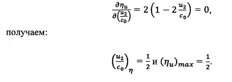
Из этого выражения получаем зависимость влияния на КПД рабочего колеса (7) первого ротора Роторного биротативного газотурбинного двигателя отношения окружной скорости (u) на окружности рабочего колеса (7) первого ротора к скорости адиабатного истечения (с0) рабочего тела, представленную на графике фиг. 9.From this expression we obtain the dependence of the ratio of the peripheral speed (u) on the circumference of the impeller (7) of the first rotor to the adiabatic outflow velocity (c 0 ) of the working fluid, presented in the graph of FIG. 9.
Таким образом, теоретически максимально достижимое КПД на окружности рабочего колеса (7) первого ротора чисто реактивной турбины (реактивность равна единице) составляет 0,5 (или 50%).Thus, the theoretically maximum achievable efficiency on the circumference of the impeller (7) of the first rotor of a purely reactive turbine (reactivity is unity) is 0.5 (or 50%).
Из графика на фиг. 9 следует так же, что с целью повышения мощности рабочего колеса (7) первого ротора Роторного биротативного газотурбинного двигателя (при сохранении расхода рабочего тела) необходимо повышать скорость истечения (с0) рабочего тела через сопла (22). Но, при этом, с целью обеспечения максимально достижимого значения КПД рабочего колеса (7) первого ротора (согласно графика на фиг. 9) необходимо повышать и скорость вращения (u) рабочего колеса (7), что в свою очередь приведет к повышению степени сжатия рабочего тела в центробежном колесе (15) первого ротора, и соответствующему повышению давления рабочего тела перед его соплами (22). Очевидно, что повышение давления рабочего тела перед соплами (22) первого ротора приводит к повышению скорости его истечения (со), а значит, и к повышению мощность рабочего колеса (7) первого ротора при обеспечении максимально достижимого уровня КПД. В свою очередь, истекающее из сопел (22) рабочего колеса (7) первого ротора потоки рабочего тела, обладающие высокой кинетической энергией, определяемой скоростью их истечения (через выражение-(mраб.тела×с0 2)/2) попадают затем в полости рабочего колеса (26) на лопатки, образованные удлиненной панелью дозвуковой части сверхзвуковых сопел (35), и передают им свой импульс энергии, идущий на увеличение момента вращения рабочего колеса (26) второго ротора. При этом потоки рабочего тела затормаживаются на этих лопатках с повышением температуры и давления торможения, и затем истекают из рабочего колеса (26) второго ротора через сверхзвуковые сопла (35) с увеличением мощности рабочего колеса (26) второго ротора, при обеспечении максимально уровня его КПД.From the graph in FIG. 9 also follows that in order to increase the power of the impeller (7) of the first rotor of the Rotary biotative gas turbine engine (while maintaining the flow rate of the working fluid), it is necessary to increase the flow rate (from 0 ) of the working fluid through nozzles (22). But, at the same time, in order to ensure the maximum achievable value of the efficiency of the impeller (7) of the first rotor (according to the graph in Fig. 9), it is necessary to increase the speed of rotation (u) of the impeller (7), which in turn will increase the degree of compression the working fluid in the centrifugal wheel (15) of the first rotor, and the corresponding increase in pressure of the working fluid in front of its nozzles (22). Obviously, an increase in the pressure of the working fluid in front of the nozzles (22) of the first rotor leads to an increase in its outflow velocity (ω), and hence to an increase in the power of the impeller (7) of the first rotor while ensuring the highest achievable efficiency level. In turn, the flows of the working fluid flowing from the nozzles (22) of the impeller (7) of the first rotor of the first rotor possessing high kinetic energy determined by the rate of their expiration (through the expression - (m working body × s 0 2 ) / 2) then fall into the cavity of the impeller (26) on the blades formed by the elongated panel of the subsonic part of the supersonic nozzles (35), and give them their energy impulse, which goes to increase the moment of rotation of the impeller (26) of the second rotor. In this case, the flow of the working fluid is inhibited on these blades with increasing temperature and braking pressure, and then flow out of the impeller (26) of the second rotor through supersonic nozzles (35) with an increase in the power of the impeller (26) of the second rotor, while ensuring its maximum level of efficiency .
Очевидно, что именно повышение степени сжатия рабочего тела в центробежном колесе (15) первого ротора, и связанное с ним соответствующее увеличение скорости (c0) истечения рабочего тела из сопел (22) рабочего колеса (7) первого ротора приводят к повышению мощности и КПД рабочего колеса (26) второго ротора заявляемого Роторного биротативного газотурбинного двигателя.Obviously, it is the increase in the degree of compression of the working fluid in the centrifugal wheel (15) of the first rotor, and the corresponding corresponding increase in the speed (c 0 ) of the expiration of the working fluid from the nozzles (22) of the impeller (7) of the first rotor lead to an increase in power and efficiency the impeller (26) of the second rotor of the inventive rotary biotative gas turbine engine.
Предварительные расчеты показывают, что значения КПД второго ротора заявляемого Роторного биротативного газотурбинного двигателя могут быть близкими расчетным значениям КПД первого ротора, при этом эффективность работы по КПД Роторного биротативного газотурбинного двигателя будет определяться арифметической суммой значений КПД совместной работы его первого и второго роторов.Preliminary calculations show that the values of the efficiency of the second rotor of the inventive Rotary turotative gas turbine engine can be close to the calculated values of the efficiency of the first rotor, while the efficiency of the efficiency of the Rotary biotational gas turbine engine will be determined by the arithmetic sum of the values of the efficiency of the joint operation of its first and second rotors.
Из Таблицы 2 видно, что при незначительной разнице в диаметре описанной окружности последних ступеней роторов, мощность заявляемого Роторного биротативного газотурбинного двигателя с одним однопоточным закрытым центробежным колесом первого ротора в 3.75-7.54 раза выше мощности Газотурбинного струйного двигателя А.В. Локотко, (по патенту РФ №2441998, от 31.08.2010 г.). В случае использования в Роторном биротативном газотурбинном двигателе рабочего колеса (7) первого ротора с двухпоточным закрытым центробежным колесом (15), представленные в Таблице 2 значения его мощности следует удваивать. При этом мощность рабочего колеса (7) первого ротора почти полностью расходуется на работу компрессоров (6) и (6') и центробежного колеса (15), а мощность рабочего колеса (26) второго ротора полностью расходуется на полезную нагрузку, а доля энергии, затрачиваемая Роторным биротативным газотурбинным двигателем на работу компрессоров (6) и (6'), и закрытого центробежного колеса (15) для сжатия окислительного рабочего тела составляет порядка 30% от всей, вырабатываемой им энергии, что меньше, чем у ближайшего аналога. Для известных и эксплуатируемых ГТД затраты мощности турбины на работу компрессора составляют до 50-70%. Столь низкие значения затрат энергии на работу компрессоров Роторного биротативного газотурбинного двигателя свидетельствуют о высокой энергоэффективности его работы по КПД.From Table 2 it can be seen that, with a slight difference in the diameter of the circumscribed circle of the last rotor stages, the power of the inventive rotary biotational gas turbine engine with one single-flow closed centrifugal wheel of the first rotor is 3.75-7.54 times higher than the capacity of the A.V. Gas turbine jet engine Lokotko, (according to the patent of the Russian Federation No. 2441998, dated August 31, 2010). If the impeller (7) of the first rotor with a double-threaded closed centrifugal wheel (15) is used in the Rotary biotational gas-turbine gas engine, its power values shown in Table 2 should be doubled. At the same time, the power of the impeller (7) of the first rotor is almost completely spent on the operation of compressors (6) and (6 ') and the centrifugal wheel (15), and the power of the impeller (26) of the second rotor is completely spent on the payload, and the share of energy The rotary biotational gas turbine engine expended on the operation of the compressors (6) and (6 '), and the closed centrifugal wheel (15) for compressing the oxidizing working fluid makes up about 30% of the total energy generated by it, which is less than that of the closest analogue. For well-known and operated gas turbine engines, the turbine power consumption for compressor operation amounts to 50-70%. Such low values of energy costs for the operation of compressors of the Rotary biotational gas turbine engine indicate the high energy efficiency of its efficiency.
Для повышения эффективности работы по КПД рабочего колеса (26) второго ротора и Роторного биротативного газотурбинного двигателя в целом так же есть определенный потенциал. Из расчетных данных, приведенных в Таблице 2 видно, что ожидаемые значения мощности и эффективности работы Роторного биротативного газотурбинного двигателя по КПД будут существенно выше мощности и эффективности работы ближайшего аналога - Газотурбинного струйного двигателя.To increase the efficiency of work on the efficiency of the impeller (26) of the second rotor and the rotary biotative gas turbine engine as a whole, there is also a certain potential. From the calculated data shown in Table 2, it can be seen that the expected values of the power and operating efficiency of the Rotary Biotational Gas Turbine Engine in terms of efficiency will be significantly higher than the power and operating efficiency of the closest analogue, the Gas Turbine Jet Engine.
По предварительным расчетным оценкам эффективности работы Роторного биротативного газотурбинного двигателя по КПД может иметь значения на уровне ни менее 65-70%. При этом порядка до 30-33% КПД может обеспечить рабочее колесо (7) первого ротора, и, по крайней мере, ни меньшую эффективность работы по КПД может обеспечить рабочее колесо (26) второго ротора двигателя.According to preliminary estimates of the efficiency of the rotary biotational gas turbine engine in terms of efficiency, it can have values of no less than 65-70%. In this case, up to 30-33% of efficiency can be achieved by the impeller (7) of the first rotor, and, at least, the impeller (26) of the second rotor of the engine can provide at least a lower efficiency.
Таким образом, путем реализации в Роторном биротативном газотурбинном двигателе независимого вращения рабочих колес первого и второго роторов на своих валах в противоположные стороны, с одинаковой, или близкой по модулю окружной скоростью, с истечением при этом продуктов неполного сгорания смеси окислительного и горючего рабочего тела из рабочего колеса (7) первого ротора с расчетным недорасширением, и со сверхзвуковой скорость, в двое превышающей окружную скорость вращения рабочего колеса (7) первого ротора, с образованием на валу (5) рабочего колеса (7) первого ротора момента вращения требуемой мощности, а так же последующим поступлением продуктов не полного сгорания смеси окислительного и горючего рабочего тела со сверхзвуковой скоростью в полость рабочего колеса (26) второго ротора, их перемешивание с поступающей в него через воздухозаборные устройства (28) и (28') дополнительной массой окислительного рабочего тела, и полное их догорание, с последующим истечением из рабочего колеса (26) второго ротора со сверхзвуковой скоростью, в двое превышающей окружную скорость вращения рабочего колеса (26) второго ротора, с образованием на валах (30) и (30') рабочего колеса (26) второго ротора момента вращения требуемой мощности, обеспечиваются высокие значения мощности и эффективности его работы по КПД, представляющие собой арифметическую сумму мощностей, и соответственно, арифметическую сумму КПД его рабочих колес (7) и (26) первого и второго роторов соответственно.Thus, by realizing in the rotary biotational gas turbine engine independent rotation of the impellers of the first and second rotors on their shafts in opposite directions, with the same or close to modulus peripheral speed, with the expiration of the products of incomplete combustion of a mixture of oxidizing and combustible working fluid from the working fluid wheels (7) of the first rotor with an estimated under-expansion, and with a supersonic speed two times higher than the peripheral speed of rotation of the impeller (7) of the first rotor, with the formation on the shaft (5) of of the wheel (7) of the first rotor of the moment of rotation of the required power, as well as the subsequent receipt of products of incomplete combustion of the mixture of the oxidizing and combustible working fluid with supersonic speed into the cavity of the impeller (26) of the second rotor, mixing them with the flowing into it through the air intake devices ( 28) and (28 ') with the additional mass of the oxidizing working fluid, and their complete burning out, with the subsequent expiration of the second rotor from the impeller (26) at a supersonic speed two times the peripheral rotation speed I of the impeller (26) of the second rotor, with the formation of the impeller (26) of the second rotor of the second rotor of the required power on the shafts (26) and (30 '), high values of power and its efficiency in terms of efficiency are provided, which are an arithmetic sum of powers, and accordingly, the arithmetic sum of the efficiency of its impellers (7) and (26) of the first and second rotors, respectively.


*) - с однопоточным закрытым центробежным колесом первого ротора, при этом режим работы рабочего колеса (7) первого ротора - неполное сгорание смеси горючего и окислителя, и истечение из сопел (22) с недорасширением.* ) - with a single-threaded closed centrifugal wheel of the first rotor, while the operating mode of the impeller (7) of the first rotor is incomplete combustion of the mixture of fuel and oxidizer, and outflow from nozzles (22) with underexpansion.
**) - сопоставим с соответствующими показателями поршневого двигателя.** ) - comparable with the corresponding performance of the piston engine.
***) - фактически будет меньше на 10-12%.*** ) - it will actually be less by 10-12%.
****) - мощность первого ротора не обеспечивает работу компрессора.**** ) - the power of the first rotor does not provide the compressor.
*****) - по газодинамической схеме - это сумма мощностей 2го, 3го, и 4го роторов.***** ) - according to the gas-dynamic scheme - this is the sum of the capacities of the 2nd , 3rd , and 4th rotors.
Claims (10)
Priority Applications (2)
| Application Number | Priority Date | Filing Date | Title |
|---|---|---|---|
| RU2019120399A RU2702317C1 (en) | 2019-07-01 | 2019-07-01 | Rotary birotate gas turbine engine |
| PCT/RU2020/000300 WO2021002773A1 (en) | 2019-07-01 | 2020-06-22 | Birotational rotary gas turbine engine |
Applications Claiming Priority (1)
| Application Number | Priority Date | Filing Date | Title |
|---|---|---|---|
| RU2019120399A RU2702317C1 (en) | 2019-07-01 | 2019-07-01 | Rotary birotate gas turbine engine |
Publications (1)
| Publication Number | Publication Date |
|---|---|
| RU2702317C1 true RU2702317C1 (en) | 2019-10-07 |
Family
ID=68170919
Family Applications (1)
| Application Number | Title | Priority Date | Filing Date |
|---|---|---|---|
| RU2019120399A RU2702317C1 (en) | 2019-07-01 | 2019-07-01 | Rotary birotate gas turbine engine |
Country Status (2)
| Country | Link |
|---|---|
| RU (1) | RU2702317C1 (en) |
| WO (1) | WO2021002773A1 (en) |
Cited By (3)
| Publication number | Priority date | Publication date | Assignee | Title |
|---|---|---|---|---|
| RU2730206C1 (en) * | 2019-08-15 | 2020-08-19 | Александр Тихонович Зыбин | Compressed combustion gas-turbine internal combustion engine |
| RU2745975C1 (en) * | 2020-06-16 | 2021-04-05 | Сергей Константинович Исаев | Rotary detonation gas turbine and the method of detonation combustion in it |
| RU2772689C1 (en) * | 2021-10-01 | 2022-05-24 | Георьги Иосипович Кемашвили | Internal combustion engine |
Citations (6)
| Publication number | Priority date | Publication date | Assignee | Title |
|---|---|---|---|---|
| US3045427A (en) * | 1960-05-02 | 1962-07-24 | James E Baize | Internal combustion power means |
| US3077075A (en) * | 1957-03-15 | 1963-02-12 | Turanciol Fuad | Rotary radial flow jet engine |
| US3200588A (en) * | 1963-02-26 | 1965-08-17 | Friedrich C Math | Jet reaction motor |
| US4628687A (en) * | 1984-05-15 | 1986-12-16 | A/S Kongsberg Vapenfabrikk | Gas turbine combustor with pneumatically controlled flow distribution |
| RU2551469C2 (en) * | 2008-10-30 | 2015-05-27 | Пауэр Дженерейшн Текнолоджис Дивелопмент Фанд Л.П. | Toroid-shaped gas turbine of boundary layer |
| RU2623592C1 (en) * | 2016-06-16 | 2017-06-28 | Акционерное общество "Военно-промышленная корпорация "Научно-производственное объединение машиностроения" | Rotary gas turbine engine |
-
2019
- 2019-07-01 RU RU2019120399A patent/RU2702317C1/en active
-
2020
- 2020-06-22 WO PCT/RU2020/000300 patent/WO2021002773A1/en active Application Filing
Patent Citations (6)
| Publication number | Priority date | Publication date | Assignee | Title |
|---|---|---|---|---|
| US3077075A (en) * | 1957-03-15 | 1963-02-12 | Turanciol Fuad | Rotary radial flow jet engine |
| US3045427A (en) * | 1960-05-02 | 1962-07-24 | James E Baize | Internal combustion power means |
| US3200588A (en) * | 1963-02-26 | 1965-08-17 | Friedrich C Math | Jet reaction motor |
| US4628687A (en) * | 1984-05-15 | 1986-12-16 | A/S Kongsberg Vapenfabrikk | Gas turbine combustor with pneumatically controlled flow distribution |
| RU2551469C2 (en) * | 2008-10-30 | 2015-05-27 | Пауэр Дженерейшн Текнолоджис Дивелопмент Фанд Л.П. | Toroid-shaped gas turbine of boundary layer |
| RU2623592C1 (en) * | 2016-06-16 | 2017-06-28 | Акционерное общество "Военно-промышленная корпорация "Научно-производственное объединение машиностроения" | Rotary gas turbine engine |
Cited By (4)
| Publication number | Priority date | Publication date | Assignee | Title |
|---|---|---|---|---|
| RU2730206C1 (en) * | 2019-08-15 | 2020-08-19 | Александр Тихонович Зыбин | Compressed combustion gas-turbine internal combustion engine |
| RU2745975C1 (en) * | 2020-06-16 | 2021-04-05 | Сергей Константинович Исаев | Rotary detonation gas turbine and the method of detonation combustion in it |
| RU2772689C1 (en) * | 2021-10-01 | 2022-05-24 | Георьги Иосипович Кемашвили | Internal combustion engine |
| RU2807828C1 (en) * | 2022-06-06 | 2023-11-21 | Иван Никифорович Хамин | Gas turbine engine with two injector blocks |
Also Published As
| Publication number | Publication date |
|---|---|
| WO2021002773A1 (en) | 2021-01-07 |
Similar Documents
| Publication | Publication Date | Title |
|---|---|---|
| RU2472026C2 (en) | Gas-turbine engine with fans of opposite rotation, which has screw gas generator with positive flow displacement | |
| US10233838B2 (en) | Recuperated gas turbine engine | |
| US6430917B1 (en) | Single rotor turbine engine | |
| KR101274127B1 (en) | High efficiency thermal engine | |
| US3685287A (en) | Re-entry type integrated gas turbine engine and method of operation | |
| RU2702317C1 (en) | Rotary birotate gas turbine engine | |
| JPH079194B2 (en) | Gas turbine engine cooling air transfer means | |
| US2809493A (en) | Centrifugal flow compressor and gas turbine power plant with a centrifugal flow compressor, toroidal combustion chamber, and centripetal flow turbine | |
| US2945619A (en) | Stage expansion reaction turbines | |
| US3093084A (en) | Pump | |
| JP6565122B2 (en) | Compressor including reinforcing disk and gas turbine including the same | |
| US3709629A (en) | Integrated flow gas turbine | |
| US3722215A (en) | Gas-turbine plant | |
| EA008268B1 (en) | Micro reaction turbine with integrated combustion chamber and rotor | |
| JP4209680B2 (en) | Turbine engine | |
| US3941501A (en) | Diffuser including a rotary stage | |
| Raheel et al. | Systematic design approach for radial blade regenerative turbomachines | |
| EP0811752B1 (en) | Centrifugal gas turbine | |
| JPH04234600A (en) | Rotor for pressure wave machine | |
| US2984751A (en) | Integral turbine-generator unit | |
| RU2623592C1 (en) | Rotary gas turbine engine | |
| JP6685321B2 (en) | Heat shield for pressure casing | |
| US3810722A (en) | Engines and compressors of the kind in which a valve device engages with a helicoidal rotor | |
| Iancu et al. | Feasibility study of integrating four-port wave rotors into ultra-micro gas turbines (UmGT) | |
| RU2742711C2 (en) | Radial birotational active-reactive turbine (variants) |