RU2701534C2 - Blade equipped with shelves, having supporting leg - Google Patents
Blade equipped with shelves, having supporting leg Download PDFInfo
- Publication number
- RU2701534C2 RU2701534C2 RU2017141278A RU2017141278A RU2701534C2 RU 2701534 C2 RU2701534 C2 RU 2701534C2 RU 2017141278 A RU2017141278 A RU 2017141278A RU 2017141278 A RU2017141278 A RU 2017141278A RU 2701534 C2 RU2701534 C2 RU 2701534C2
- Authority
- RU
- Russia
- Prior art keywords
- blade
- section
- longitudinal
- shelf
- workpiece
- Prior art date
Links
Images
Classifications
-
- F—MECHANICAL ENGINEERING; LIGHTING; HEATING; WEAPONS; BLASTING
- F01—MACHINES OR ENGINES IN GENERAL; ENGINE PLANTS IN GENERAL; STEAM ENGINES
- F01D—NON-POSITIVE DISPLACEMENT MACHINES OR ENGINES, e.g. STEAM TURBINES
- F01D5/00—Blades; Blade-carrying members; Heating, heat-insulating, cooling or antivibration means on the blades or the members
- F01D5/12—Blades
- F01D5/22—Blade-to-blade connections, e.g. for damping vibrations
- F01D5/225—Blade-to-blade connections, e.g. for damping vibrations by shrouding
-
- B—PERFORMING OPERATIONS; TRANSPORTING
- B29—WORKING OF PLASTICS; WORKING OF SUBSTANCES IN A PLASTIC STATE IN GENERAL
- B29B—PREPARATION OR PRETREATMENT OF THE MATERIAL TO BE SHAPED; MAKING GRANULES OR PREFORMS; RECOVERY OF PLASTICS OR OTHER CONSTITUENTS OF WASTE MATERIAL CONTAINING PLASTICS
- B29B11/00—Making preforms
- B29B11/14—Making preforms characterised by structure or composition
- B29B11/16—Making preforms characterised by structure or composition comprising fillers or reinforcement
-
- B—PERFORMING OPERATIONS; TRANSPORTING
- B29—WORKING OF PLASTICS; WORKING OF SUBSTANCES IN A PLASTIC STATE IN GENERAL
- B29C—SHAPING OR JOINING OF PLASTICS; SHAPING OF MATERIAL IN A PLASTIC STATE, NOT OTHERWISE PROVIDED FOR; AFTER-TREATMENT OF THE SHAPED PRODUCTS, e.g. REPAIRING
- B29C70/00—Shaping composites, i.e. plastics material comprising reinforcements, fillers or preformed parts, e.g. inserts
- B29C70/04—Shaping composites, i.e. plastics material comprising reinforcements, fillers or preformed parts, e.g. inserts comprising reinforcements only, e.g. self-reinforcing plastics
- B29C70/06—Fibrous reinforcements only
- B29C70/10—Fibrous reinforcements only characterised by the structure of fibrous reinforcements, e.g. hollow fibres
- B29C70/16—Fibrous reinforcements only characterised by the structure of fibrous reinforcements, e.g. hollow fibres using fibres of substantial or continuous length
- B29C70/22—Fibrous reinforcements only characterised by the structure of fibrous reinforcements, e.g. hollow fibres using fibres of substantial or continuous length oriented in at least two directions forming a two dimensional structure
- B29C70/222—Fibrous reinforcements only characterised by the structure of fibrous reinforcements, e.g. hollow fibres using fibres of substantial or continuous length oriented in at least two directions forming a two dimensional structure the structure being shaped to form a three dimensional configuration
-
- B—PERFORMING OPERATIONS; TRANSPORTING
- B29—WORKING OF PLASTICS; WORKING OF SUBSTANCES IN A PLASTIC STATE IN GENERAL
- B29D—PRODUCING PARTICULAR ARTICLES FROM PLASTICS OR FROM SUBSTANCES IN A PLASTIC STATE
- B29D99/00—Subject matter not provided for in other groups of this subclass
- B29D99/0025—Producing blades or the like, e.g. blades for turbines, propellers, or wings
-
- F—MECHANICAL ENGINEERING; LIGHTING; HEATING; WEAPONS; BLASTING
- F01—MACHINES OR ENGINES IN GENERAL; ENGINE PLANTS IN GENERAL; STEAM ENGINES
- F01D—NON-POSITIVE DISPLACEMENT MACHINES OR ENGINES, e.g. STEAM TURBINES
- F01D5/00—Blades; Blade-carrying members; Heating, heat-insulating, cooling or antivibration means on the blades or the members
- F01D5/12—Blades
- F01D5/26—Antivibration means not restricted to blade form or construction or to blade-to-blade connections or to the use of particular materials
-
- F—MECHANICAL ENGINEERING; LIGHTING; HEATING; WEAPONS; BLASTING
- F01—MACHINES OR ENGINES IN GENERAL; ENGINE PLANTS IN GENERAL; STEAM ENGINES
- F01D—NON-POSITIVE DISPLACEMENT MACHINES OR ENGINES, e.g. STEAM TURBINES
- F01D5/00—Blades; Blade-carrying members; Heating, heat-insulating, cooling or antivibration means on the blades or the members
- F01D5/12—Blades
- F01D5/28—Selecting particular materials; Particular measures relating thereto; Measures against erosion or corrosion
- F01D5/282—Selecting composite materials, e.g. blades with reinforcing filaments
-
- F—MECHANICAL ENGINEERING; LIGHTING; HEATING; WEAPONS; BLASTING
- F01—MACHINES OR ENGINES IN GENERAL; ENGINE PLANTS IN GENERAL; STEAM ENGINES
- F01D—NON-POSITIVE DISPLACEMENT MACHINES OR ENGINES, e.g. STEAM TURBINES
- F01D5/00—Blades; Blade-carrying members; Heating, heat-insulating, cooling or antivibration means on the blades or the members
- F01D5/30—Fixing blades to rotors; Blade roots ; Blade spacers
- F01D5/3007—Fixing blades to rotors; Blade roots ; Blade spacers of axial insertion type
-
- B—PERFORMING OPERATIONS; TRANSPORTING
- B29—WORKING OF PLASTICS; WORKING OF SUBSTANCES IN A PLASTIC STATE IN GENERAL
- B29C—SHAPING OR JOINING OF PLASTICS; SHAPING OF MATERIAL IN A PLASTIC STATE, NOT OTHERWISE PROVIDED FOR; AFTER-TREATMENT OF THE SHAPED PRODUCTS, e.g. REPAIRING
- B29C70/00—Shaping composites, i.e. plastics material comprising reinforcements, fillers or preformed parts, e.g. inserts
- B29C70/04—Shaping composites, i.e. plastics material comprising reinforcements, fillers or preformed parts, e.g. inserts comprising reinforcements only, e.g. self-reinforcing plastics
- B29C70/06—Fibrous reinforcements only
- B29C70/10—Fibrous reinforcements only characterised by the structure of fibrous reinforcements, e.g. hollow fibres
- B29C70/16—Fibrous reinforcements only characterised by the structure of fibrous reinforcements, e.g. hollow fibres using fibres of substantial or continuous length
- B29C70/24—Fibrous reinforcements only characterised by the structure of fibrous reinforcements, e.g. hollow fibres using fibres of substantial or continuous length oriented in at least three directions forming a three dimensional structure
-
- B—PERFORMING OPERATIONS; TRANSPORTING
- B29—WORKING OF PLASTICS; WORKING OF SUBSTANCES IN A PLASTIC STATE IN GENERAL
- B29C—SHAPING OR JOINING OF PLASTICS; SHAPING OF MATERIAL IN A PLASTIC STATE, NOT OTHERWISE PROVIDED FOR; AFTER-TREATMENT OF THE SHAPED PRODUCTS, e.g. REPAIRING
- B29C70/00—Shaping composites, i.e. plastics material comprising reinforcements, fillers or preformed parts, e.g. inserts
- B29C70/04—Shaping composites, i.e. plastics material comprising reinforcements, fillers or preformed parts, e.g. inserts comprising reinforcements only, e.g. self-reinforcing plastics
- B29C70/28—Shaping operations therefor
- B29C70/40—Shaping or impregnating by compression not applied
- B29C70/42—Shaping or impregnating by compression not applied for producing articles of definite length, i.e. discrete articles
- B29C70/46—Shaping or impregnating by compression not applied for producing articles of definite length, i.e. discrete articles using matched moulds, e.g. for deforming sheet moulding compounds [SMC] or prepregs
- B29C70/48—Shaping or impregnating by compression not applied for producing articles of definite length, i.e. discrete articles using matched moulds, e.g. for deforming sheet moulding compounds [SMC] or prepregs and impregnating the reinforcements in the closed mould, e.g. resin transfer moulding [RTM], e.g. by vacuum
-
- B—PERFORMING OPERATIONS; TRANSPORTING
- B29—WORKING OF PLASTICS; WORKING OF SUBSTANCES IN A PLASTIC STATE IN GENERAL
- B29K—INDEXING SCHEME ASSOCIATED WITH SUBCLASSES B29B, B29C OR B29D, RELATING TO MOULDING MATERIALS OR TO MATERIALS FOR MOULDS, REINFORCEMENTS, FILLERS OR PREFORMED PARTS, e.g. INSERTS
- B29K2307/00—Use of elements other than metals as reinforcement
- B29K2307/04—Carbon
-
- B—PERFORMING OPERATIONS; TRANSPORTING
- B29—WORKING OF PLASTICS; WORKING OF SUBSTANCES IN A PLASTIC STATE IN GENERAL
- B29L—INDEXING SCHEME ASSOCIATED WITH SUBCLASS B29C, RELATING TO PARTICULAR ARTICLES
- B29L2031/00—Other particular articles
- B29L2031/08—Blades for rotors, stators, fans, turbines or the like, e.g. screw propellers
-
- F—MECHANICAL ENGINEERING; LIGHTING; HEATING; WEAPONS; BLASTING
- F05—INDEXING SCHEMES RELATING TO ENGINES OR PUMPS IN VARIOUS SUBCLASSES OF CLASSES F01-F04
- F05D—INDEXING SCHEME FOR ASPECTS RELATING TO NON-POSITIVE-DISPLACEMENT MACHINES OR ENGINES, GAS-TURBINES OR JET-PROPULSION PLANTS
- F05D2220/00—Application
- F05D2220/30—Application in turbines
- F05D2220/36—Application in turbines specially adapted for the fan of turbofan engines
-
- F—MECHANICAL ENGINEERING; LIGHTING; HEATING; WEAPONS; BLASTING
- F05—INDEXING SCHEMES RELATING TO ENGINES OR PUMPS IN VARIOUS SUBCLASSES OF CLASSES F01-F04
- F05D—INDEXING SCHEME FOR ASPECTS RELATING TO NON-POSITIVE-DISPLACEMENT MACHINES OR ENGINES, GAS-TURBINES OR JET-PROPULSION PLANTS
- F05D2230/00—Manufacture
- F05D2230/50—Building or constructing in particular ways
- F05D2230/53—Building or constructing in particular ways by integrally manufacturing a component, e.g. by milling from a billet or one piece construction
-
- F—MECHANICAL ENGINEERING; LIGHTING; HEATING; WEAPONS; BLASTING
- F05—INDEXING SCHEMES RELATING TO ENGINES OR PUMPS IN VARIOUS SUBCLASSES OF CLASSES F01-F04
- F05D—INDEXING SCHEME FOR ASPECTS RELATING TO NON-POSITIVE-DISPLACEMENT MACHINES OR ENGINES, GAS-TURBINES OR JET-PROPULSION PLANTS
- F05D2240/00—Components
- F05D2240/20—Rotors
- F05D2240/30—Characteristics of rotor blades, i.e. of any element transforming dynamic fluid energy to or from rotational energy and being attached to a rotor
-
- F—MECHANICAL ENGINEERING; LIGHTING; HEATING; WEAPONS; BLASTING
- F05—INDEXING SCHEMES RELATING TO ENGINES OR PUMPS IN VARIOUS SUBCLASSES OF CLASSES F01-F04
- F05D—INDEXING SCHEME FOR ASPECTS RELATING TO NON-POSITIVE-DISPLACEMENT MACHINES OR ENGINES, GAS-TURBINES OR JET-PROPULSION PLANTS
- F05D2300/00—Materials; Properties thereof
- F05D2300/60—Properties or characteristics given to material by treatment or manufacturing
- F05D2300/603—Composites; e.g. fibre-reinforced
- F05D2300/6034—Orientation of fibres, weaving, ply angle
-
- Y—GENERAL TAGGING OF NEW TECHNOLOGICAL DEVELOPMENTS; GENERAL TAGGING OF CROSS-SECTIONAL TECHNOLOGIES SPANNING OVER SEVERAL SECTIONS OF THE IPC; TECHNICAL SUBJECTS COVERED BY FORMER USPC CROSS-REFERENCE ART COLLECTIONS [XRACs] AND DIGESTS
- Y02—TECHNOLOGIES OR APPLICATIONS FOR MITIGATION OR ADAPTATION AGAINST CLIMATE CHANGE
- Y02T—CLIMATE CHANGE MITIGATION TECHNOLOGIES RELATED TO TRANSPORTATION
- Y02T50/00—Aeronautics or air transport
- Y02T50/60—Efficient propulsion technologies, e.g. for aircraft
Landscapes
- Engineering & Computer Science (AREA)
- Mechanical Engineering (AREA)
- General Engineering & Computer Science (AREA)
- Chemical & Material Sciences (AREA)
- Materials Engineering (AREA)
- Composite Materials (AREA)
- Textile Engineering (AREA)
- Structures Of Non-Positive Displacement Pumps (AREA)
- Moulding By Coating Moulds (AREA)
- Woven Fabrics (AREA)
- Turbine Rotor Nozzle Sealing (AREA)
Abstract
Description
Область техники, к которой относится изобретениеFIELD OF THE INVENTION
Изобретение относится к заготовке для лопатки газотурбинного двигателя, а также к моноблочной лопатке, которую можно выполнить при помощи такой заготовки, к лопаточному колесу и к газотурбинному двигателю, содержащим такую лопатку.The invention relates to a blank for a blade of a gas turbine engine, as well as to a monoblock blade, which can be performed using such a blank, to a blade wheel and to a gas turbine engine containing such a blade.
Такую заготовку можно использовать для выполнения лопаток, содержащих аэродинамические полки, оснащенные поддерживающими подкосами. Такие лопатки могут быть, в частности, лопатками вентилятора авиационного турбореактивного двигателя, хотя это является всего лишь одним из примеров.Such a workpiece can be used to make blades containing aerodynamic shelves equipped with supporting struts. Such blades may be, in particular, fan blades of an aircraft turbojet engine, although this is just one example.
Уровень техникиState of the art
Для уменьшения массы авиационных турбореактивных двигателей и, следовательно, для снижения расхода топлива этих турбореактивных двигателей, как известно, некоторые лопатки двигателя изготавливают из композиционного материала, который является намного более легким, чем традиционно используемый до настоящего времени металл.To reduce the weight of aircraft turbojet engines and, consequently, to reduce the fuel consumption of these turbojet engines, it is known that some engine blades are made of composite material, which is much lighter than the metal traditionally used to date.
Для этого, как известно, в настоящее время применяют технологии трехмерного тканья с целью получения волокнистых заготовок и, в конечном счете, композитных лопаток очень высокого качества. В частности, в документе WO 2014/076408 описан способ тканья волокнистой заготовки, позволяющий получать моноблочные лопатки, имеющие полки корытца и спинки, причем эти полки имеют постоянную толщину.For this, as is known, three-dimensional weaving technologies are currently being applied to obtain fibrous preforms and, ultimately, very high quality composite blades. In particular, document WO 2014/076408 describes a method for weaving a fibrous preform, which makes it possible to obtain monoblock blades having shelves of troughs and backs, these shelves having a constant thickness.
Однако эти полки должны отвечать многим требованиям и обеспечивать многочисленные функции. В основном такие полки должны обеспечивать аэродинамическую функцию для образования проточного тракта и направления воздушного потока в турбореактивном двигателе. Вместе с тем, они должны также обеспечивать механическую прочность, гарантированную для всех фаз полета, а также логичное интегрирование в окружающую среду двигателя, в частности, избегая возмущений воздушного потока на выходе. Следовательно, необходимо очень точно контролировать геометрию площадок, причем в течение всей работы двигателя и независимо от фазы полета.However, these shelves must meet many requirements and provide multiple functions. Basically, such shelves should provide an aerodynamic function for the formation of a flow path and the direction of air flow in a turbojet engine. At the same time, they should also provide mechanical strength guaranteed for all phases of flight, as well as logical integration into the environment of the engine, in particular, avoiding perturbations of the air stream at the outlet. Therefore, it is necessary to very accurately control the geometry of the sites, and during the entire operation of the engine and regardless of the phase of flight.
В ходе испытаний и моделирования на таких лопатках авторы изобретения установили, что различные зоны этих площадок, полученных посредством трехмерного тканья, деформируются более или менее значительно под влиянием центробежных усилий, действующих во время работы газотурбинного двигателя. Авторы изобретения заметили, в частности, что деформация зоны полки тем больше, чем дальше эта зона вынесена относительно пера. During testing and modeling on such blades, the inventors found that the various zones of these sites obtained by three-dimensional weaving are deformed more or less significantly under the influence of centrifugal forces acting during operation of the gas turbine engine. The inventors noticed, in particular, that the deformation of the zone of the shelf is greater, the farther this zone is made relative to the pen.
Во время работы эти полки имеют неровности формы, которые могут нарушать воздушный поток и, следовательно, влиять на КПД двигателя. Кроме того, авторы изобретения отметили, что прогиб зависит, кроме всего прочего, от длины консольной части. Таким образом, поскольку консольность различается между полками спинки и корытца двух последовательных лопаток, происходит нарушение непрерывности прогиба в этом граничном месте и появляется риск перекрывания площадок.During operation, these shelves have irregular shapes that can disrupt the air flow and, therefore, affect the efficiency of the engine. In addition, the inventors noted that the deflection depends, inter alia, on the length of the cantilever part. Thus, since the cantilever is different between the shelves of the back and troughs of two consecutive blades, there is a violation of the continuity of the deflection at this boundary place and there is a risk of overlapping platforms.
Таким образом, существует реальная потребность в волокнистой заготовке, лопатке, лопаточном колесе и газотурбинном двигателе, не имеющих вышеупомянутых недостатков известных систем.Thus, there is a real need for a fiber preform, a blade, a blade wheel and a gas turbine engine that do not have the aforementioned disadvantages of the known systems.
Раскрытие сущности изобретенияDisclosure of the invention
Объектом изобретения является заготовка лопатки газотурбинного двигателя, полученная посредством трехмерного тканья, содержащая первый продольный участок, выполненный с возможностью образовать по меньшей мере часть хвостовика лопатки, второй продольный участок, продолжающий вверх первый продольный участок и выполненный с возможностью образовать по меньшей мере часть ножки, третий продольный участок, продолжающий вверх второй продольный участок и выполненный с возможностью образовать перьевую часть, первый поперечный участок, проходящий поперечно от соединения между вторым и третьим продольными участками и выполненный с возможностью образовать первую полку, и первый наклонный участок, проходящий от соединения между первым и вторым продольными участками до первого поперечного участка и выполненный с возможностью образовать поддерживающий подкос для первой полки.The object of the invention is the preparation of a blade of a gas turbine engine obtained by three-dimensional textile, comprising a first longitudinal section configured to form at least a portion of the shank of the blade, a second longitudinal section extending upwardly on the first longitudinal section and configured to form at least a portion of the leg, the third a longitudinal portion extending upwardly into a second longitudinal portion and configured to form a feather portion, a first transverse portion, transverse from the connection between the second and third longitudinal sections and configured to form a first flange, and a first inclined section extending from the connection between the first and second longitudinal sections to the first transverse section and configured to form a supporting strut for the first flange.
Благодаря такой заготовке, можно получить моноблочную лопатку, содержащую хвостовик лопатки, ножку, перьевую часть и по меньшей мере одну полку, оснащенную поддерживающим подкосом, позволяющим удерживать полку с преодолением центробежной силы во время работы газотурбинного двигателя. Это позволяет повысить жесткость полки и уменьшить ее деформации во время работы.Thanks to such a preform, it is possible to obtain a monoblock blade containing a shank of the blade, a leg, a feather part and at least one shelf equipped with a supporting strut that allows holding the shelf with overcoming centrifugal force during operation of the gas turbine engine. This allows you to increase the stiffness of the shelf and reduce its deformation during operation.
Действительно, центробежные усилия, действующие на полку, воспринимаются поддерживающим подкосом и передаются на хвостовик или на ножку лопатки, которые являются конструктивными частями лопатки. При этом во время работы полка сохраняет относительно стабильный профиль, не мешающий или лишь в незначительной степени мешающий прохождению воздушного потока.Indeed, centrifugal forces acting on the shelf are perceived by the supporting strut and transferred to the shank or to the blade leg, which are the structural parts of the blade. Moreover, during operation, the shelf maintains a relatively stable profile that does not interfere or only slightly interferes with the passage of the air flow.
Благодаря этой заготовке, можно использовать преимущества моноблочной лопатки, выполненной посредством трехмерного тканья (выигрыш в массе; уменьшение числа деталей; упрощение монтажа и обслуживания и т.д.), одновременно обеспечивая аэродинамическую стабильность воздушного потока.Thanks to this blank, it is possible to use the advantages of a monoblock blade made by means of three-dimensional weaving (gain in mass; reduction in the number of parts; simplification of installation and maintenance, etc.), while ensuring aerodynamic stability of the air flow.
Кроме того, эта конфигурация позволяет также уменьшить нарушение непрерывности, обычно отмечаемое во время работы на границе раздела между соседними полками. Кроме того, поддерживающий подкос позволяет также уменьшить риск перекрывания полки соседней полкой, например, в случае попадания в двигатель птицы.In addition, this configuration also reduces the discontinuity commonly observed during operation at the interface between adjacent shelves. In addition, the support strut can also reduce the risk of overlapping a shelf with an adjacent shelf, for example, if a bird enters the engine.
В настоящем описании термины «продольный», «поперечный», «нижний», «верхний» и производные от них термины определены относительно главного направления рассматриваемой лопатки, при этом хвостовик лопатки находится с нижней стороны лопатки в соответствии с такой системой отсчета; термины «ближний», «дальний» и производные от них термины определены относительно пера лопатки; термины «осевой», «радиальный», «тангенциальный» и производные от них термины определены относительно главной оси колеса, содержащего эти лопатки, то есть, как правило, оси газотурбинного двигателя. Под «осевой плоскостью» следует понимать плоскость, проходящую через главную ось газотурбинного двигателя, а под «радиальной плоскостью» - плоскость, перпендикулярную к этой главной оси; под «продольной плоскостью» следует понимать плоскость, параллельную главному направлению лопатки и перпендикулярную к направлению расширения хвостовика лопатки: следовательно, такая продольная плоскость является радиальной плоскостью в системе координат газотурбинного двигателя. Кроме того, термины «вход» и «выход» определены относительно прохождения воздуха в газотурбинном двигателе.In the present description, the terms “longitudinal”, “transverse”, “lower”, “upper” and derivatives derived from them are defined with respect to the main direction of the blade in question, while the shank of the blade is located on the underside of the blade in accordance with such a reference frame; the terms “near”, “distant” and their derivatives are defined with respect to the feather of the blade; the terms “axial”, “radial”, “tangential” and the terms derived from them are defined relative to the main axis of the wheel containing these blades, that is, as a rule, the axis of the gas turbine engine. By “axial plane” is meant a plane passing through the main axis of the gas turbine engine, and by “radial plane” is a plane perpendicular to this main axis; “longitudinal plane” should be understood as a plane parallel to the main direction of the blade and perpendicular to the direction of expansion of the shank of the blade: therefore, such a longitudinal plane is a radial plane in the coordinate system of a gas turbine engine. In addition, the terms “inlet” and “outlet” are defined with respect to the passage of air in a gas turbine engine.
Наконец, под «трехмерным тканьем» следует понимать технологию тканья, при которой нити утка проходят внутри матрицы нитей основы, образуя трехмерную сетку нитей с трехмерным переплетением: все слои нитей такой волокнистой структуры выполняют на одном этапе тканья внутри трехмерного ткацкого станка.Finally, “three-dimensional weaving” should be understood as weaving technology, in which the weft threads pass inside the warp matrix, forming a three-dimensional network of threads with three-dimensional weaving: all layers of threads of such a fibrous structure are performed at one textile stage inside a three-dimensional weaving machine.
В некоторых вариантах осуществления первый наклонный участок является сплошным от входного конца до выходного конца полки. Таким образом, полка поддерживается по всей своей длине, что позволяет более эффективно уменьшить ее деформации.In some embodiments, the first inclined portion is continuous from the inlet end to the outlet end of the shelf. Thus, the shelf is supported along its entire length, which makes it possible to more effectively reduce its deformation.
В других вариантах осуществления первый наклонный участок содержит несколько лапок, распределенных от входа к выходу. Эта конфигурация позволяет уменьшить массу заготовки и, следовательно, конечной лопатки. Она облегчает также извлечение лопатки из пресс-формы после затвердевания заготовки.In other embodiments, the first oblique portion comprises several legs distributed from inlet to outlet. This configuration allows to reduce the mass of the workpiece and, consequently, the final blade. It also facilitates the removal of the blade from the mold after the workpiece has hardened.
В некоторых вариантах осуществления дальний конец первого наклонного участка проходит вдоль дальнего конца первого поперечного участка. Таким образом, центробежные усилия воспринимаются на уровне полки, где они являются самыми значительными, то есть где полка имеет наибольший вынос относительно перьевой части.In some embodiments, the distal end of the first inclined portion extends along the distal end of the first transverse portion. Thus, centrifugal forces are perceived at the shelf level, where they are the most significant, that is, where the shelf has the greatest extension relative to the feather part.
В некоторых вариантах осуществления дальний конец первого наклонного участка связан с первым поперечным участком. Это облегчает придание формы заготовке с целью ее затвердевания, чтобы получить конечную лопатку, в которой полка и поддерживающий подкос неподвижно соединены между собой. Это крепление можно осуществить при помощи любого средства крепления, например, сшивания, склеивания, заклепок или скрепок.In some embodiments, the distal end of the first inclined portion is associated with the first transverse portion. This makes it easier to shape the workpiece in order to solidify it, in order to obtain a final blade in which the shelf and the supporting strut are motionlessly interconnected. This fastening can be carried out using any fastening means, for example, stitching, gluing, rivets or staples.
В некоторых вариантах осуществления первый наклонный участок является по существу плоским. Это облегчает передачу усилий до хвостовика или до ножки лопатки.In some embodiments, the first inclined portion is substantially flat. This facilitates the transfer of forces to the shank or to the leg of the scapula.
В некоторых вариантах осуществления первый продольный участок имеет по существу постоянную длину от входного конца до выходного конца заготовки. Это облегчает выполнение пропуска переплетения для разделения второго продольного участка и первого наклонного участка.In some embodiments, the first longitudinal portion has a substantially constant length from the inlet end to the outlet end of the preform. This facilitates the implementation of skipping weaving to separate the second longitudinal section and the first inclined section.
В некоторых вариантах осуществления длина второго продольного участка увеличивается от входного конца заготовки до ее выходного конца. Это представляет особый интерес в случае лопатки вентилятора для обеспечения непрерывности проточного воздушного тракта между входной обечайкой небольшого диаметра и выходным барабаном большего диаметра.In some embodiments, the length of the second longitudinal portion is increased from the input end of the preform to its output end. This is of particular interest in the case of a fan blade to ensure continuity of the flow path between the inlet shell of a small diameter and the output drum of a larger diameter.
В некоторых вариантах осуществления волокнистая заготовка содержит второй поперечный участок, проходящий поперечно от соединения между вторым и третьим продольными участками в продолжении и противоположно первому поперечному участку и выполненный с возможностью образовать вторую полку, и заготовка дополнительно содержит второй наклонный участок, проходящий от соединения между первым и вторым продольными участками до второго поперечного участка и выполненный с возможностью образовать поддерживающий подкос для второй полки.In some embodiments, the fibrous preform comprises a second transverse portion extending transversely from the connection between the second and third longitudinal portions in a continuation and opposite to the first transverse portion and configured to form a second shelf, and the preform further comprises a second inclined portion extending from the connection between the first and the second longitudinal sections to the second transverse section and configured to form a supporting strut for the second shelf.
Понятно, что все отличительные признаки, упомянутые выше для первого поперечного участка и для первого наклонного участка, можно транспонировать на второй поперечный участок и на второй наклонный участок.It is understood that all the distinguishing features mentioned above for the first transverse section and for the first inclined section can be transposed to the second transverse section and to the second inclined section.
В других вариантах осуществления волокнистая заготовка содержит только один поперечный участок и только один наклонный участок. В этом случае конечная лопатка имеет единственную полку, проходящую до соседней лопатки, что улучшает равномерность воздушного потока между двумя соседними лопатками. В этом случае предпочтительно полка находится со стороны спинки: это облегчает придание формы и затем извлечение лопатки из пресс-формы после затвердевания заготовки.In other embodiments, the fiber preform comprises only one transverse section and only one inclined section. In this case, the final blade has a single shelf extending to the adjacent blade, which improves the uniformity of the air flow between two adjacent blades. In this case, preferably the shelf is on the back side: this facilitates shaping and then removing the blade from the mold after the workpiece has hardened.
В некоторых вариантах осуществления заготовка содержит переходный элемент на уровне соединения между вторым и третьим продольными участками на ее поверхности, противоположной первому поперечному элементу. Этот переходный элемент обеспечивает взаимодействие с соответствующей полкой соседней лопатки. В зависимости от своей конфигурации он может защищать лопатку, полученную из этой заготовки, в случае столкновения с соседней лопаткой, например, при попадании птицы в двигатель, и/или может блокировать положение полки соседней лопатки в противодействие центробежным силам. In some embodiments, the preform comprises a transition element at a level of connection between the second and third longitudinal portions on its surface opposite the first transverse element. This transition element provides interaction with the corresponding shelf of an adjacent blade. Depending on its configuration, it can protect the blade obtained from this workpiece in the event of a collision with an adjacent blade, for example, when a bird enters the engine, and / or can block the position of the shelf of the adjacent blade in opposition to centrifugal forces.
В некоторых вариантах осуществления переходный элемент представляет собой присоединяемую металлическую полосу. Эту полосу можно, например, закрепить на заготовке перед этапом совместного литья.In some embodiments, the transition element is an attachable metal strip. This strip can, for example, be fixed to the workpiece before the co-casting step.
В некоторых вариантах осуществления переходный элемент представляет собой тканую полосу, проходящую от соединения между вторым и третьим продольными участками.In some embodiments, the transition element is a woven strip extending from the connection between the second and third longitudinal portions.
В некоторых вариантах осуществления нити, используемые для тканья заготовки, являются углеродными нитями. Вместе с тем, речь может идти о любом другом типе нитей, например, о стекловолокнах или о кевларе.In some embodiments, the yarns used to weave the preform are carbon yarns. However, we can talk about any other type of thread, for example, fiberglass or Kevlar.
В некоторых вариантах осуществления переплетение, применяемое для трехмерного тканья заготовки, является переплетением типа интерлок 3D. Вместе с тем, тканье наружных поверхностей заготовки может быть в основном двухмерным, например, типа сатина.In some embodiments, the weave used for three-dimensional weaving of the preform is an interlock 3D weave. However, the weaving of the outer surfaces of the preform may be substantially two-dimensional, such as, for example, sateen.
Объектом настоящего изобретения является также лопатка для газотурбинного двигателя, содержащая хвостовик лопатки, ножку, проходящую вверх от хвостовика лопатки, перьевую часть, проходящую вверх от ножки, полку, проходящую поперечно к перьевой части на уровне соединения между ножкой и перьевой частью, и поддерживающий подкос, проходящий между хвостовиком или ножкой, с одной стороны, и полкой, с другой стороны.The object of the present invention is also a blade for a gas turbine engine, comprising a shank of the blade, a leg extending upward from the shank of the blade, a feather portion extending upward from the leg, a shelf extending transverse to the feather portion at the level of the connection between the leg and the feather portion, and supporting the strut, passing between the shank or leg, on the one hand, and the shelf, on the other hand.
Понятно, что эта лопатка соответствует тому, что можно получить при помощи описанной выше заготовки. Вместе с тем, такую лопатку можно также получить при помощи другого способа и выполнить из другого материала: например, такую лопатку можно выполнить, например, из металла при помощи соответствующего способа литья. В любом случае все описанные выше отличительные признаки и преимущества напрямую относятся к этой лопатке, какой бы ни была технология ее получения.It is clear that this blade corresponds to what can be obtained using the preform described above. At the same time, such a blade can also be obtained using another method and made of another material: for example, such a blade can be made, for example, of metal using an appropriate casting method. In any case, all the distinguishing features and advantages described above are directly related to this blade, whatever the technology of its production.
В некоторых вариантах осуществления лопатка выполнена моноблочной из композиционного материала при помощи волокнистой заготовки согласно любому из вышеуказанных вариантов осуществления, при этом указанной заготовке придана форма в пресс-форме, и она погружена в матрицу.In some embodiments, the implementation of the blade is made monoblock of composite material using a fibrous preform according to any of the above embodiments, while the specified preform is shaped in a mold, and it is immersed in the matrix.
В некоторых вариантах осуществления матрица является органической. В частности, речь может идти об эпоксидной смоле.In some embodiments, the matrix is organic. In particular, we can talk about epoxy resin.
Объектом настоящего изобретения является также лопаточное колесо для газотурбинного двигателя, содержащее множество лопаток согласно любому из предыдущих вариантов осуществления.An object of the present invention is also a blade wheel for a gas turbine engine, comprising a plurality of blades according to any of the previous embodiments.
Речь может идти о колесе ротора, таком как вентилятор, в котором лопатки расположены в угловом направлении вокруг вращающейся ступицы, или о колесе статора, в котором лопатки расположены в угловом направлении внутри неподвижной обечайки.This may be a rotor wheel, such as a fan, in which the blades are located in the angular direction around the rotating hub, or about the stator wheel, in which the blades are located in the angular direction inside the stationary shell.
Объектом настоящего изобретения является также газотурбинный двигатель, содержащий по меньшей мере одну лопатку или одно лопаточное колесо согласно любому из предыдущих вариантов осуществления.An object of the present invention is also a gas turbine engine comprising at least one blade or one blade wheel according to any of the previous embodiments.
Вышеуказанные, а также описанные ниже отличительные признаки и преимущества будут более очевидны из нижеследующего подробного описания примеров осуществления предложенных заготовки, лопатки, лопаточного колеса и газотурбинного двигателя. Это подробное описание представлено со ссылками на прилагаемые чертежи.The above, as well as the following distinctive features and advantages will be more apparent from the following detailed description of exemplary embodiments of the proposed blanks, blades, impellers and gas turbine engines. This detailed description is presented with reference to the accompanying drawings.
Краткое описание чертежейBrief Description of the Drawings
Прилагаемые чертежи являются схематичными и призваны иллюстрировать принципы изобретения. На этих чертежах от одной фигуры к другой идентичные элементы (или части элемента) имеют одинаковые обозначения. Кроме того, элементы (или части элемента), принадлежащие к разным примерам осуществления, но имеющие аналогичную функцию, обозначены на фигурах цифровыми позициями, увеличенными на 100, 200, и т.д.The accompanying drawings are schematic and are intended to illustrate the principles of the invention. In these drawings, from one figure to another, identical elements (or parts of an element) have the same designations. In addition, elements (or parts of an element) belonging to different examples of implementation, but having a similar function, are indicated in the figures by digital positions increased by 100, 200, etc.
На фиг. 1 показан заявленный газотурбинный двигатель в плоскости осевого разреза;In FIG. 1 shows the claimed gas turbine engine in the plane of the axial section;
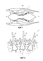
на фиг. 2 схематично показана часть заявленного лопаточного колеса, вид в радиальном разрезе;in FIG. 2 schematically shows a part of the claimed blade wheel, a view in radial section;
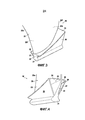
на фиг. 3 показана часть лопатки согласно примеру осуществления, вид в перспективе;in FIG. 3 shows a part of a blade according to an embodiment, a perspective view;
на фиг. 4 показана часть лопатки, изображенной на фиг. 3, вид в перспективе под другим углом;in FIG. 4 shows a portion of the blade of FIG. 3, a perspective view from a different angle;
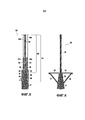
на фиг. 5 схематично показана заготовка, соответствующая этому примеру лопатки, перед приданием ей формы;in FIG. 5 schematically shows a preform corresponding to this example of a blade before shaping it;
на фиг. 6 схематично показана заготовка, соответствующая этому примеру лопатки, после придания ей формы;in FIG. 6 schematically shows a preform corresponding to this example of a blade after being shaped;
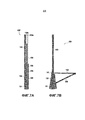
на фиг. 7А схематично показан второй пример заготовки перед приданием ей формы;in FIG. 7A schematically shows a second example of a preform before shaping it;
на фиг. 7В схематично показана заготовка согласно этому второму примеру после придания ей формы.in FIG. 7B schematically shows a preform according to this second example after being shaped.
Осуществление изобретенияThe implementation of the invention
Для более конкретного описания изобретения ниже со ссылками на прилагаемые чертежи детально представлены примеры его осуществления. Вместе с тем, необходимо напомнить, что изобретение не ограничивается этими примерами.For a more specific description of the invention, examples of its implementation are presented in detail below with reference to the accompanying drawings. However, it must be recalled that the invention is not limited to these examples.
На фиг. 1 представлен вид в разрезе по вертикальной плоскости, проходящей через главную ось А, заявленного двухконтурного турбореактивного двигателя 1. От входа к выходу по направлению прохождения воздушного потока он содержит вентилятор 2, компрессор 3 низкого давления, компрессор 4 высокого давления, камеру 5 сгорания, турбину 6 высокого давления и турбину 7 низкого давления.In FIG. 1 shows a sectional view along a vertical plane passing through the main axis A of the declared turbofan engine 1. From the inlet to the outlet in the direction of air flow, it comprises a
Как показано на фиг. 2, вентилятор 2 оснащен множеством лопаток 10 вентилятора, установленных в угловом направлении вокруг оси А на диске 11, установленном на валу низкого давления газотурбинного двигателя 1.As shown in FIG. 2,
Такая лопатка вентилятора показана на фиг. 3 и 4. Она содержит хвостовик 21 лопатки типа «ласточкин хвост», выполненный с возможностью захождения в паз 12 диска 11 для своего крепления на диске 11. Этот хвостовик 21 лопатки продолжен вверх ножкой 22, затем пером 23, имеющим поверхность 23е спинки и поверхность 23i корытца, каждая из которых расположена от входа к выходу между передней кромкой 23а и задней кромкой 23f.Such a fan blade is shown in FIG. 3 and 4. It contains the shank of the dovetail type of the
Кроме того, лопатка 10 содержит полку 24 спинки, расположенную поперечно со стороны спинки лопатки, начиная от соединения между ножкой 22 и пером 23, и полку 25 корытца, расположенную поперечно со стороны корытца лопатки, начиная от соединения между ножкой 22 и пером 23.In addition, the
Лопатка 10 дополнительно содержит поддерживающий подкос 26 спинки, проходящий от соединения между хвостовиком 21 лопатки и ножкой 22 до дальнего конца полки 24 спинки, и, аналогично, поддерживающий подкос 27 корытца, проходящий от соединения между хвостовиком 21 лопатки и ножкой 22 до дальнего конца полки 25 корытца. Таким образом, с каждой стороны лопатки 10 каждая полка 24, 25 образует вместе с поддерживающим подкосом 26, 27 и ножкой 22 полый кессон 29, имеющий по существу треугольный профиль.The
Как показано на фиг. 3 и 4, зона соединения между хвостовиком 21 лопатки и ножкой 22 находится по существу на постоянной высоте вдоль всей лопатки 10 от входа к выходу. С другой стороны, высота ножки 22 увеличивается от входа к выходу таким образом, что кессоны 29 имеют форму воронки, открывающейся в сторону выхода лопатки 10.As shown in FIG. 3 and 4, the connection zone between the
В этом примере лопатка 10 выполнена моноблочно посредством трехмерного тканья волокнистой заготовки 30, придания формы этой заготовке 30 и нагнетания органической смолы в соответствии с процессом RTM (“resin transfer molding”- литье смолы под давлением), известным специалисту в данной области.In this example, the
На фиг. 5 показана полученная посредством трехмерного тканья первичная заготовка 30’ этой заготовки 30, позволяющая реализовать этот пример лопатки 10. На фиг.6 показана конечная заготовка 30 после обрезания и придания формы этой первичной заготовке 30’. Эта первичная заготовка 30’ будет описана снизу вверх, то есть от входа к выходу в направлении Т тканья. Вместе с тем, понятно, что тканье можно осуществлять, начиная от другого конца и в другом направлении.In FIG. 5 shows the primary blank 30 ’of this blank 30 obtained by three-dimensional weaving, allowing this example of the
В этом примере осуществления заготовка 30 выткана посредством трехмерного тканья из углеродных волокон в соответствии с переплетением интерлок 3D. При этом только поверхности заготовки 30 выполнены посредством двухмерного тканья в соответствии с переплетением типа сатина.In this embodiment, the
На нижнем конце тканье начинается с выполнения первого продольного участка 31, который в дальнейшем образует хвостовик 21 лопатки 10.At the lower end, the textile begins with the implementation of the first
Над этим первым продольным участком 31 начинается первая зона D1 пропуска переплетения, в которой выполняют нижнюю свободную стенку 36а, второй продольный участок 32 и вторую свободную стенку 37а посредством трехмерного тканья с пропуском переплетения совместно с плоскостями 38 пропуска переплетения. Методы тканья, обеспечивающие такой пропуск переплетения, хорошо известны в области трехмерного тканья. Предпочтительно эти первая и вторая свободные стенки имеют толщину двух или трех слоев нитей, то есть толщину примерно 2 или 3 мм. Эта первая зона пропуска переплетения может начинаться на любой высоте будущей ножки.Above this first
Над вторым продольным участком 32 начинается вторая зона D2 пропуска переплетения, в которое выполняют продолжение первой свободной стенки 36а, третью свободную стенку 34а, третий продольный участок 33, четвертую свободную стенку 35а и продолжение второй свободной стенки 37а посредством трехмерного тканья с пропуском переплетения совместно с двумя новыми плоскостями 39 пропуска переплетения, которые добавляются к первым плоскостям 38 пропуска переплетения, тканье которых продолжается дальше.Above the second
После завершения тканья третью и четвертую свободные стенки 34а и 35а обрезают, чтобы получить первый поперечный участок 34, который образует в дальнейшем полку 24 спинки лопатки 10, и второй поперечный участок 35, который образует в дальнейшем полку 25 корытца лопатки 10.After completing the textile, the third and fourth
Первую и вторую свободные стенки 36а и 37а тоже обрезают, чтобы получить первый наклонный участок 36, который образует в дальнейшем поддерживающий подкос 26 спинки лопатки 10, и второй наклонный участок 37, который образует в дальнейшем поддерживающий подкос 27 лопатки.The first and second
Следует отметить, что в данном случае определения «наклонный», «поперечный» и «продольный» приведены в зависимости от конечного положения рассматриваемого участка заготовки 30, при этом тканье поперечных и наклонных участков обязательно производят в продольном направлении, после чего их сгибают соответственно в поперечном и наклонном направлениях.It should be noted that in this case, the definitions of “inclined”, “transverse” and “longitudinal” are given depending on the final position of the considered section of the
Затем первичную заготовку 30’ можно увлажнить для ее размягчения и для более легкого разделения волокон. После этого первичную заготовку 30’ помещают в формовочную пресс-форму, внутреннее пространство которой соответствует требуемой для заготовки 30 геометрии.Then, the primary preform 30 ’can be moistened to soften it and to more easily separate the fibers. After this, the primary blank 30 ’is placed in a molding mold, the inner space of which corresponds to the geometry required for the blank 30.
После этого заготовку 30 сушат, чтобы она затвердела, что позволяет зафиксировать геометрию, заданную во время формовки. Как показано на фиг. 6, дальний конец каждого наклонного участка 36, 37 проходит вдоль дальнего конца соответствующего поперечного участка 34, 35. Концы этих участков можно сшить для их прочного соединения.After that, the
Наконец, заготовку 30 помещают в пресс-форму для литья под давлением, размеры которой соответствуют размерам конечной лопатки 10. Кроме того, в кессоны, образованные поперечными 34, 35 и наклонными 36, 37 участками помещают вставки, чтобы сохранить форму этих участков и помешать матрице заполнять внутренний объем этих кессонов. Затем нагнетают матрицу, в данном случае эпоксидную смолу. Такое нагнетание можно, например, производить в рамках известного процесса RTM (“resin transfer molding”). После затвердевания из кессонов 29 удаляют вставки и получают необходимую лопатку 10.Finally, the blank 30 is placed in an injection molding mold, the dimensions of which correspond to the dimensions of the
Естественно, описанный выше пример является лишь одним примером среди многих других возможных примеров, которые специалист в данной области может легко определить. В частности, можно предусмотреть другие пропуски переплетения или применять другие технологии тканья, такие как перекрещивание слоев, выходы слоев или переходы толщины, чтобы получить аналогичную геометрию заготовки. В частности, специалист в данной области может найти многочисленные примеры тканья в документе WO 2014/076408.Naturally, the example described above is just one example among many other possible examples that one skilled in the art can easily determine. In particular, other weaving passes may be provided or other weaving techniques, such as layer crossing, layer outlets or thickness transitions, may be applied to obtain similar preform geometry. In particular, one of skill in the art can find numerous examples of weaving in WO 2014/076408.
В частности, в варианте осуществления первую и вторую свободные стенки 36а и 37а обрезают в определенных местах до зоны соединения между первым и вторым продольными участками. В этом случае полученные наклонные участки 36, 37 по сути образованы множеством отстоящих друг от друга лапок.In particular, in an embodiment, the first and second
На фиг. 7А и 7В показан второй пример заготовки 130. В этом втором примере заготовка 130 содержит только один поперечный участок 134 и только один наклонный участок 136, предусмотренные со стороны спинки. Таким образом, лопатка, полученная из такой заготовки 130, имеет только одну полку, предусмотренную на ее стороне спинки. Эта полка и ее поддерживающий подкос являются в этом случае более длинными, чтобы заполнить любое пространство, разделяющее две последовательные лопатки внутри вентилятора.In FIG. 7A and 7B show a second example of the
Таким образом, метод тканья первичной заготовки 130’ этой заготовки 130 является аналогичным методу тканья из первого примера, за исключением того, что только первую и третью свободные станки 136а, 134а выполняют посредством тканья с пропуском переплетения вместе с продольными участками 132 и 133 первичной заготовки 130’. Кроме того, эти свободные стенки 134а и 136а обрезают на большей высоте, чтобы поперечный 134 и наклонный 136 участки имели более значительную длину.Thus, the weaving method of the primary preform 130 'of this
Кроме того, в этом втором примере вдоль всей заготовки 130 крепят металлическую полосу 141 на уровне соединения между вторым и третьим продольными участками 132, 133 на стороне, противоположной поперечному участку 134. Во время нагнетания матрицы эта металлическая полоса 141 оказывается заключенной в поверхность лопатки и образует, таким образом, переходный элемент, выполненный с возможностью взаимодействия с дальним концом полки соседней лопатки.In addition, in this second example, a
Описанные в настоящей заявке варианты или примеры осуществления представлены в качестве иллюстрации и не являются ограничивающими, и на основании этой заявки специалист в данной области может легко изменять эти варианты или примеры осуществления или предусмотреть другие варианты или примеры, не выходя при этом за рамки объема изобретения.The embodiments or embodiments described herein are illustrative and not restrictive, and based on this application, one skilled in the art can easily modify these options or embodiments or provide other options or examples without departing from the scope of the invention.
Кроме того, различные отличительные признаки этих вариантов или примеров осуществления можно использовать отдельно или в комбинации. Если эти отличительные признаки комбинируют, их комбинации могут соответствовать описанным выше или другим, поскольку изобретение не ограничивается конкретными комбинациями, описанными в настоящей заявке. В частности, если только не указано иное, отличительный признак, описанный в связи с одним вариантом или примером осуществления, можно аналогично применить для другого варианта или примера осуществления.In addition, the various distinguishing features of these options or embodiments may be used alone or in combination. If these distinguishing features are combined, their combinations may be as described above or otherwise, since the invention is not limited to the specific combinations described in this application. In particular, unless otherwise indicated, the distinguishing feature described in connection with one embodiment or embodiment may be similarly applied to another embodiment or embodiment.
Claims (23)
Applications Claiming Priority (3)
| Application Number | Priority Date | Filing Date | Title |
|---|---|---|---|
| FR1553851A FR3035678B1 (en) | 2015-04-29 | 2015-04-29 | DAWN WITH PLATFORMS HAVING A RESTRAINT LEG |
| FR1553851 | 2015-04-29 | ||
| PCT/FR2016/050982 WO2016174346A1 (en) | 2015-04-29 | 2016-04-26 | Vane equipped with platforms comprising a retaining leg |
Publications (3)
| Publication Number | Publication Date |
|---|---|
| RU2017141278A RU2017141278A (en) | 2019-05-29 |
| RU2017141278A3 RU2017141278A3 (en) | 2019-08-01 |
| RU2701534C2 true RU2701534C2 (en) | 2019-09-27 |
Family
ID=53484038
Family Applications (1)
| Application Number | Title | Priority Date | Filing Date |
|---|---|---|---|
| RU2017141278A RU2701534C2 (en) | 2015-04-29 | 2016-04-26 | Blade equipped with shelves, having supporting leg |
Country Status (9)
| Country | Link |
|---|---|
| US (1) | US10619493B2 (en) |
| EP (1) | EP3288738B1 (en) |
| JP (1) | JP6771488B2 (en) |
| CN (1) | CN107530909B (en) |
| BR (1) | BR112017023163B1 (en) |
| CA (1) | CA2983970C (en) |
| FR (1) | FR3035678B1 (en) |
| RU (1) | RU2701534C2 (en) |
| WO (1) | WO2016174346A1 (en) |
Families Citing this family (5)
| Publication number | Priority date | Publication date | Assignee | Title |
|---|---|---|---|---|
| FR3063448B1 (en) * | 2017-03-01 | 2019-04-05 | Safran Aircraft Engines | PREFORME AND AUBE MONOBLOC FOR TURBOMACHINE |
| US11280202B2 (en) | 2020-04-06 | 2022-03-22 | Raytheon Technologies Corporation | Balanced composite root region for a blade of a gas turbine engine |
| US11834960B2 (en) | 2022-02-18 | 2023-12-05 | General Electric Company | Methods and apparatus to reduce deflection of an airfoil |
| FR3132927B1 (en) * | 2022-02-21 | 2024-02-16 | Safran Aircraft Engines | Blade preform, blade and turbomachine blade fixing system |
| US11846192B1 (en) | 2023-04-21 | 2023-12-19 | General Electric Company | Airfoil assembly with a trunnion and spar |
Citations (6)
| Publication number | Priority date | Publication date | Assignee | Title |
|---|---|---|---|---|
| US4686134A (en) * | 1984-12-29 | 1987-08-11 | Nippon Mayer Co., Ltd. | Three-dimensional structural member |
| US6446675B1 (en) * | 2001-07-05 | 2002-09-10 | Albany International Techniweave, Inc. | Minimum distortion 3D woven preforms |
| US20030056847A1 (en) * | 2001-09-12 | 2003-03-27 | Schmidt Ronald P. | Woven preform for structural joints |
| US20100105269A1 (en) * | 2008-10-29 | 2010-04-29 | Jonathan Goering | Pi-Shaped Preform |
| FR2953885A1 (en) * | 2009-12-14 | 2011-06-17 | Snecma | TURBOMACHINE DRAFT IN COMPOSITE MATERIAL AND METHOD FOR MANUFACTURING THE SAME |
| RU122679U1 (en) * | 2012-05-10 | 2012-12-10 | Общество с ограниченной ответственностью "Агрисовгаз" | HINGE SHIELD FORMWORK |
Family Cites Families (16)
| Publication number | Priority date | Publication date | Assignee | Title |
|---|---|---|---|---|
| US2656146A (en) * | 1948-04-08 | 1953-10-20 | Curtiss Wright Corp | Turbine blade construction |
| US3294364A (en) * | 1962-01-02 | 1966-12-27 | Gen Electric | Rotor assembly |
| US4343593A (en) * | 1980-01-25 | 1982-08-10 | The United States Of America As Represented By The Secretary Of The Air Force | Composite blade for turbofan engine fan |
| FR2608674B1 (en) * | 1986-12-17 | 1991-04-19 | Snecma | CERAMIC BLADE TURBINE WHEEL |
| FR2639402B1 (en) * | 1988-11-23 | 1990-12-28 | Snecma | TURBOMACHINE ROTOR WING DISC |
| US6821087B2 (en) * | 2002-01-21 | 2004-11-23 | Honda Giken Kogyo Kabushiki Kaisha | Flow-rectifying member and its unit and method for producing flow-rectifying member |
| FR2855440B1 (en) * | 2003-05-27 | 2006-07-14 | Snecma Moteurs | METHOD FOR MANUFACTURING A HOLLOW DAWN FOR TURBOMACHINE |
| US8251651B2 (en) * | 2009-01-28 | 2012-08-28 | United Technologies Corporation | Segmented ceramic matrix composite turbine airfoil component |
| FR2946999B1 (en) * | 2009-06-18 | 2019-08-09 | Safran Aircraft Engines | CMC TURBINE DISPENSER ELEMENT, PROCESS FOR MANUFACTURING SAME, AND DISPENSER AND GAS TURBINE INCORPORATING SAME. |
| DE102009060650A1 (en) * | 2009-12-22 | 2011-06-30 | Keller, Walter, 66994 | Aeroacoustic rotor blade for a wind turbine and wind turbine equipped therewith |
| US9033673B2 (en) * | 2010-06-28 | 2015-05-19 | Herakles | Turbomachine blade or vane having complementary asymmetrical geometry |
| US9212560B2 (en) * | 2011-06-30 | 2015-12-15 | United Technologies Corporation | CMC blade with integral 3D woven platform |
| FR2983428B1 (en) * | 2011-12-01 | 2014-01-17 | Snecma Propulsion Solide | PROCESS FOR MANUFACTURING A TURBOMACHINE BLADE IN COMPOSITE MATERIAL WITH INTEGRATED PLATFORMS |
| JP6038178B2 (en) * | 2012-01-09 | 2016-12-07 | スネクマ | Fiber preform for turbine engine blade made of composite material and integrated platform and method of making the same |
| BR112015010844B1 (en) * | 2012-11-13 | 2021-04-06 | Snecma | FIBER PREFORM FOR A TURBOMACHINE SHOVEL, TURBOMACHINE SHOVEL, INTERMEDIATE TURBOMACHINE HOUSING, TURBOMACHINE FAN, AND, TURBOMACHINE |
| US9976426B2 (en) * | 2015-07-21 | 2018-05-22 | United Technologies Corporation | Fan platform with stiffening feature |
-
2015
- 2015-04-29 FR FR1553851A patent/FR3035678B1/en not_active Expired - Fee Related
-
2016
- 2016-04-26 CA CA2983970A patent/CA2983970C/en active Active
- 2016-04-26 CN CN201680024872.9A patent/CN107530909B/en active Active
- 2016-04-26 RU RU2017141278A patent/RU2701534C2/en active
- 2016-04-26 JP JP2017556610A patent/JP6771488B2/en active Active
- 2016-04-26 WO PCT/FR2016/050982 patent/WO2016174346A1/en active Application Filing
- 2016-04-26 BR BR112017023163-8A patent/BR112017023163B1/en active IP Right Grant
- 2016-04-26 US US15/569,134 patent/US10619493B2/en active Active
- 2016-04-26 EP EP16722314.8A patent/EP3288738B1/en active Active
Patent Citations (8)
| Publication number | Priority date | Publication date | Assignee | Title |
|---|---|---|---|---|
| US4686134A (en) * | 1984-12-29 | 1987-08-11 | Nippon Mayer Co., Ltd. | Three-dimensional structural member |
| US6446675B1 (en) * | 2001-07-05 | 2002-09-10 | Albany International Techniweave, Inc. | Minimum distortion 3D woven preforms |
| RU2225902C1 (en) * | 2001-07-05 | 2004-03-20 | Олбэни Интернэшнл Текниуив, Инк. | Flat fabric for forming structure of three-dimensional configuration |
| US20030056847A1 (en) * | 2001-09-12 | 2003-03-27 | Schmidt Ronald P. | Woven preform for structural joints |
| US20100105269A1 (en) * | 2008-10-29 | 2010-04-29 | Jonathan Goering | Pi-Shaped Preform |
| RU2530378C2 (en) * | 2008-10-29 | 2014-10-10 | Олбани Энджиниэрд Композитс, Инк. | U-shaped preform |
| FR2953885A1 (en) * | 2009-12-14 | 2011-06-17 | Snecma | TURBOMACHINE DRAFT IN COMPOSITE MATERIAL AND METHOD FOR MANUFACTURING THE SAME |
| RU122679U1 (en) * | 2012-05-10 | 2012-12-10 | Общество с ограниченной ответственностью "Агрисовгаз" | HINGE SHIELD FORMWORK |
Also Published As
| Publication number | Publication date |
|---|---|
| CA2983970A1 (en) | 2016-11-03 |
| FR3035678B1 (en) | 2017-05-12 |
| WO2016174346A1 (en) | 2016-11-03 |
| CN107530909B (en) | 2020-08-21 |
| US20180100400A1 (en) | 2018-04-12 |
| FR3035678A1 (en) | 2016-11-04 |
| US10619493B2 (en) | 2020-04-14 |
| RU2017141278A (en) | 2019-05-29 |
| CN107530909A (en) | 2018-01-02 |
| RU2017141278A3 (en) | 2019-08-01 |
| EP3288738B1 (en) | 2019-04-03 |
| CA2983970C (en) | 2023-03-07 |
| BR112017023163A2 (en) | 2018-07-24 |
| BR112017023163B1 (en) | 2021-11-16 |
| JP2018523041A (en) | 2018-08-16 |
| JP6771488B2 (en) | 2020-10-21 |
| EP3288738A1 (en) | 2018-03-07 |
Similar Documents
| Publication | Publication Date | Title |
|---|---|---|
| RU2699857C2 (en) | Blade equipped with shelves containing inserts | |
| RU2701534C2 (en) | Blade equipped with shelves, having supporting leg | |
| RU2699649C2 (en) | Blade equipped with shelves, having stiffness element | |
| US10508559B2 (en) | Monobloc preform and blade for turbo machine | |
| US10253640B2 (en) | Platform of small hub-tip ratio | |
| RU2690350C2 (en) | Composite blade comprising a flange with a stiffening element | |
| US10131073B2 (en) | Monobloc blade preform and module for a turbo machine intermediate casing | |
| US20220372882A1 (en) | Woven fibrous preform for producing a composite part, especially a turbomachine blade | |
| US11795825B2 (en) | Inter-blade platform with a sacrificial box section | |
| JP6616402B2 (en) | Composite guide vanes with staggered mounting flanges for gas turbine engines | |
| CN110352119B (en) | Preform and one-piece blade for a turbomachine | |
| US20220333493A1 (en) | Preform for a composite blade | |
| US11933194B2 (en) | Fan or propeller vane for an aircraft turbomachine and method for manufacturing same |