RU2699503C1 - Device for electro-flotation purification of aqueous solutions - Google Patents
Device for electro-flotation purification of aqueous solutions Download PDFInfo
- Publication number
- RU2699503C1 RU2699503C1 RU2018132065A RU2018132065A RU2699503C1 RU 2699503 C1 RU2699503 C1 RU 2699503C1 RU 2018132065 A RU2018132065 A RU 2018132065A RU 2018132065 A RU2018132065 A RU 2018132065A RU 2699503 C1 RU2699503 C1 RU 2699503C1
- Authority
- RU
- Russia
- Prior art keywords
- chamber
- electroflotation
- flotation
- aqueous solutions
- blocks
- Prior art date
Links
- 238000005188 flotation Methods 0.000 title claims abstract description 33
- 238000000746 purification Methods 0.000 title claims abstract description 15
- 239000007864 aqueous solution Substances 0.000 title claims abstract description 12
- 239000010802 sludge Substances 0.000 claims abstract description 11
- 239000007788 liquid Substances 0.000 abstract description 14
- 238000004140 cleaning Methods 0.000 abstract description 5
- 238000000034 method Methods 0.000 abstract description 5
- 230000000694 effects Effects 0.000 abstract description 2
- 239000003344 environmental pollutant Substances 0.000 abstract description 2
- 231100000719 pollutant Toxicity 0.000 abstract description 2
- 230000007717 exclusion Effects 0.000 abstract 1
- 239000000126 substance Substances 0.000 abstract 1
- XLYOFNOQVPJJNP-UHFFFAOYSA-N water Substances O XLYOFNOQVPJJNP-UHFFFAOYSA-N 0.000 description 24
- 239000007789 gas Substances 0.000 description 12
- 239000012530 fluid Substances 0.000 description 9
- 239000000356 contaminant Substances 0.000 description 8
- 239000002245 particle Substances 0.000 description 7
- 238000005868 electrolysis reaction Methods 0.000 description 6
- 239000008213 purified water Substances 0.000 description 6
- 208000012868 Overgrowth Diseases 0.000 description 5
- 239000000725 suspension Substances 0.000 description 5
- 238000005192 partition Methods 0.000 description 4
- 229920006395 saturated elastomer Polymers 0.000 description 3
- 238000011109 contamination Methods 0.000 description 2
- 239000006260 foam Substances 0.000 description 2
- 239000013049 sediment Substances 0.000 description 2
- 239000007787 solid Substances 0.000 description 2
- 239000000701 coagulant Substances 0.000 description 1
- 238000000605 extraction Methods 0.000 description 1
- 238000011049 filling Methods 0.000 description 1
- 238000001914 filtration Methods 0.000 description 1
- 239000008394 flocculating agent Substances 0.000 description 1
- 230000005484 gravity Effects 0.000 description 1
- 239000001257 hydrogen Substances 0.000 description 1
- 229910052739 hydrogen Inorganic materials 0.000 description 1
- 125000004435 hydrogen atom Chemical class [H]* 0.000 description 1
- 239000000203 mixture Substances 0.000 description 1
- 239000001301 oxygen Substances 0.000 description 1
- 229910052760 oxygen Inorganic materials 0.000 description 1
- UUWCBFKLGFQDME-UHFFFAOYSA-N platinum titanium Chemical compound [Ti].[Pt] UUWCBFKLGFQDME-UHFFFAOYSA-N 0.000 description 1
- 238000001556 precipitation Methods 0.000 description 1
- 239000007790 solid phase Substances 0.000 description 1
- 229910001220 stainless steel Inorganic materials 0.000 description 1
- 239000010935 stainless steel Substances 0.000 description 1
- 238000004659 sterilization and disinfection Methods 0.000 description 1
Images
Classifications
-
- B—PERFORMING OPERATIONS; TRANSPORTING
- B03—SEPARATION OF SOLID MATERIALS USING LIQUIDS OR USING PNEUMATIC TABLES OR JIGS; MAGNETIC OR ELECTROSTATIC SEPARATION OF SOLID MATERIALS FROM SOLID MATERIALS OR FLUIDS; SEPARATION BY HIGH-VOLTAGE ELECTRIC FIELDS
- B03D—FLOTATION; DIFFERENTIAL SEDIMENTATION
- B03D1/00—Flotation
- B03D1/14—Flotation machines
-
- C—CHEMISTRY; METALLURGY
- C02—TREATMENT OF WATER, WASTE WATER, SEWAGE, OR SLUDGE
- C02F—TREATMENT OF WATER, WASTE WATER, SEWAGE, OR SLUDGE
- C02F1/00—Treatment of water, waste water, or sewage
- C02F1/46—Treatment of water, waste water, or sewage by electrochemical methods
- C02F1/461—Treatment of water, waste water, or sewage by electrochemical methods by electrolysis
- C02F1/465—Treatment of water, waste water, or sewage by electrochemical methods by electrolysis by electroflotation
Landscapes
- Chemical & Material Sciences (AREA)
- Engineering & Computer Science (AREA)
- Life Sciences & Earth Sciences (AREA)
- General Chemical & Material Sciences (AREA)
- Electrochemistry (AREA)
- Hydrology & Water Resources (AREA)
- Chemical Kinetics & Catalysis (AREA)
- Environmental & Geological Engineering (AREA)
- Water Supply & Treatment (AREA)
- Organic Chemistry (AREA)
- Biotechnology (AREA)
- Physical Water Treatments (AREA)
- Water Treatment By Electricity Or Magnetism (AREA)
Abstract
Description
Изобретение относится к области флотации и может использоваться для очистки водных растворов.The invention relates to the field of flotation and can be used for the purification of aqueous solutions.
Известен аналог напорный флотатор в описание изобретения к патенту №2049732 МПК C02F 1/24, B03D 1/14 от 06.01.1993, опубл. 10.12.1995, содержащий емкость с внутренней цилиндрической перегородкой, флотационную, отстойную и фильтрирующую камеры, устройство для подачи водовоздушной смеси, снабженное эжектором, подающий трубопровод и патрубок отвода очищенной жидкости, отличающийся тем, что подающий трубопровод расположен в нижней части емкости, флотатор снабжен установленной внутри цилиндрической перегородки воронкой с диффузором, размещенным над подающим трубопроводом, при этом цилиндрическая перегородка нижней частью соединена со стенкой емкости, а в верхней части снабжена обращенным большим основанием вверх раструбом с наклонным срезом на торце, расположенным на противоположной стороне относительно патрубка отвода очищенной жидкости.Known analogue pressure flotator in the description of the invention to patent No. 2049732 IPC C02F 1/24,
Недостатки: недостаточно высокое качество очистки жидкости.Disadvantages: insufficiently high quality cleaning fluid.
Известен аналог в описание изобретения к патенту № WO 1994011308, МПК B03D 1/02; B03D 1/14; C02F 1/465, от 26.05.1994, способ очистки водных растворов или тому подобного, когда удаляемый компонент, например, в растворенном или твердом состоянии, превращается в твердую фазу, причем указанный способ включает добавление осадителя, коагулирующих агентов и/или флокулянты; отделение больших твердых частиц от суспензии, полученной таким образом путем осаждения; и удаление оставшихся компонентов из суспензии посредством электрофлотации. Удаление оставшихся компонентов осуществляется в соответствии со следующими этапами: - путем электрофлотации на первой стадии способа суспензия насыщается в процессе турбулентности с пузырьками электролитических газов, плотностью электрического тока, превышающей 20 мА/см2, и - на второй стадии пена разделяется ламинарным потоком жидкости, плотность электрического тока ниже 20 мА/см2. Электрофлотационное устройство для очистки водных растворов или тому подобное, состоящее из камеры, заполняющих и разгрузочных отсеков, устройства для удаления пены и электродных блоков, в котором электроды являются параллельными листовыми элементами, в котором камера содержит камеру газонасыщения, в которой установлен электрод блок для насыщения суспензии газом, выделяемым во время электролиза, - флотационный отсек, в котором установлен электродный блок для флотации, - супрессор потока суспензии многоклеточной структуры, установленный выше электродный блок в флотационном отсеке и - регулируемую разделительную стенку, установленную между камерой газонасыщения и флотационной камерой.The analogue is known in the description of the invention to patent No. WO 1994011308, IPC
Недостатки: недостаточно высокое качество очистки жидкости, зарастание межэлектродного пространства камеры газонасыщения заряженными частицами загрязнений.Disadvantages: insufficiently high quality of liquid purification, overgrowth of the interelectrode space of the gas saturation chamber with charged particles of contamination.
Известен наиболее близкий аналог электрофлотатор с устройством преобразования турбулентного потока жидкости в ламинарный в описание изобретения к патенту №2459667, МПК B03D 1/14 (2006.01), от 13.04.2011, опубл. 27.08.2012, состоящий из корпуса с перегородкой для двух емкостей, двух кассет электродов, источника электропитания, скребкового инструмента, насоса подачи жидкости. Во второй емкости, в которой турбулентный поток опускается ко второй кассете электродов, проходит через блок закрепленных рядами по всей площади второй емкости профильных труб, расположенных вертикально, при этом турбулентный поток разбивается на малые по мощности турбулентные потоки в соответствии с количеством профильных труб в блоке, и за счет выравнивания давления во всех этих потоках при равных скоростях движения происходит преобразование этих маломощных потоков в ламинарный поток большой мощности, проходящий через вторую кассету электродов.The closest analogue is known as an electroflotator with a device for converting a turbulent fluid flow into a laminar one in the description of the invention to patent No. 2459667, IPC
Недостатки: недостаточно высокое качество очистки жидкости, зарастание межэлектродного пространства камеры газонасыщения заряженными частицами загрязнений.Disadvantages: insufficiently high quality of liquid purification, overgrowth of the interelectrode space of the gas saturation chamber with charged particles of contamination.
Технический результат: повышение качества очистки жидкости при исключении зарастания межэлектродного пространства загрязняющими веществами.Effect: improving the quality of liquid purification with the exception of overgrowth of the interelectrode space with contaminants.
Технический результат в устройстве электрофлотационной очистки водных растворов содержащем корпус с камерой электрофлотации, блок электродов с источником электропитания, скребковый механизм, карман для флотошлама, достигается за счет того, что снабжено камерой напорной флотации, которая содержит прикрепленную к ней перфорированную трубу и внешний сатуратор, а камера электрофлотации содержит четное количество блоков электродов, при этом над блоками электродов расположены блоки ромбовидных ячеек.The technical result in the device for electroflotation purification of aqueous solutions containing a housing with an electroflotation chamber, an electrode block with an electric power source, a scraper mechanism, a flotation sludge pocket is achieved due to the fact that it is equipped with a pressure flotation chamber that contains a perforated tube attached to it and an external saturator, and the electroflotation chamber contains an even number of electrode blocks, with blocks of diamond-shaped cells located above the electrode blocks.
Повышение качества очистки жидкости при исключении зарастания межэлектродного пространства загрязняющими веществами достигается за счет того что, устройство электрофлотационной очистки водных растворов заполняют чистой водой, включают внешний сатуратор, подают напряжение на блоки электродов, в камере напорной флотации через отверстия перфорированной трубы выделяется растворенный воздух в виде мелких пузырьков с размерами 100 мкм, обеспечивая режим напорной флотации. Входной поток очищаемой жидкости через входной патрубок подают в камеру напорной флотации. Частицы загрязнений размерами не менее 100 мкм в результате прилипания к ним пузырьков воздуха приобретают плавучесть и всплывают на поверхность жидкости и извлекается уже на этом этапе очитки. Из камеры напорной флотации, поток жидкости перемещается в камеру электрофлотации, равномерно распределяясь в нисходящем потоке через ромбовидные ячейки. В результате электролиза воды на блоках электродов выделяются газы - кислород водород, которые в виде мельчайших пузырьков размерами 10 мкм всплывают на поверхность воды, удерживая слой флотошлама, который с помощью скребкового механизма удаляют в приемный карман для флотошлама. При этом очищенная вода обеззараживается. Часть очищенной воды через патрубок поступает во внешний сатуратор, где происходит насыщение воды воздухом, а затем через отверстия перфорированной трубы в камеру напорной флотации. Благодаря конструкции блоков с ромбовидными ячейками, пространство между корпусом и блоком ромбовидных ячеек не забивается загрязняющими веществами, в отличие от использования прямоугольных ячеек в аналогах. В аналогах в режиме электрофлотации, при прохождении сквозь электроды загрязненной воды происходит зарастание межэлектродного пространства загрязняющими веществами, причем особенно быстро это происходит, если загрязняющие воду частицы обладают зарядом, а в заявляемом устройстве использование камеры напорной флотации позволяет очистить жидкость уже до режима электрофлотации.Improving the quality of liquid purification with the exception of overgrowth of the interelectrode space with contaminants is achieved due to the fact that the electroflotation purification device for aqueous solutions is filled with clean water, an external saturator is turned on, voltage is applied to the electrode blocks, dissolved air is released in the pressure-flotation chamber through the openings of the perforated tube in the form of small bubbles with a size of 100 microns, providing pressure flotation mode. The input stream of the liquid being cleaned through the inlet pipe is fed into the pressure flotation chamber. Particles of contaminants with a size of at least 100 microns as a result of adhesion of air bubbles to them acquire buoyancy and float to the surface of the liquid and sediments are removed at this stage. From the pressure flotation chamber, the fluid flow moves into the electroflotation chamber, uniformly distributed in a downward flow through the diamond-shaped cells. As a result of water electrolysis, gases are released on the electrode blocks - oxygen, hydrogen, which in the form of
По сравнению с чисто напорной флотацией, где объем рециркулируемой воды достигает 30% от производительности напорного флотатора в заявляемом устройстве объем рециркулируемой воды составляет не более 3% от производительности аппарата, что позволяет уменьшить его габаритные размеры по сравнению с напорным флотатором равной производительности, повысить качество очистки жидкости и гарантировать потоки 10 м3/ч через 1 м2 поверхности водного зеркала. Внутренний поток воды в камере электрофлотации 10 Qвнутр, равный произведению скорости движения жидкости на площадь поперечного сечения, состоит из суммы входного (выходного) потока Qцикл потока на рециркуляцию части жидкости Qвход.. Qвнутр=Qвход+Qцикл. В чисто напорных флотаторах Qцикл достигает до 30% от Qвход. В заявляемом устройстве это соотношение не более 3%. За счет этого, заявляемое устройство при равной производительности с напорными флотаторами обладает значительно меньшими габаритами и более высокой степенью очистки.Compared with purely pressure flotation, where the volume of recirculated water reaches 30% of the productivity of the pressure flotator in the inventive device, the volume of recirculated water is not more than 3% of the capacity of the apparatus, which allows to reduce its overall dimensions compared to the pressure flotator of equal productivity, to improve the quality of cleaning liquids and guarantee flows of 10 m3 / h through 1 m2 of the surface of the water mirror. The internal water flow in the electroflotation chamber 10 Q int , equal to the product of the fluid velocity and the cross-sectional area, consists of the sum of the input (output) flow Q the flow cycle to recirculate part of the fluid Q inlet. . Q int = Q input + Q cycle . In pure pressure flotators, the Q cycle reaches up to 30% of the Q input. In the inventive device, this ratio is not more than 3%. Due to this, the inventive device with equal performance with pressure flotators has significantly smaller dimensions and a higher degree of purification.
Наличие отличительных от прототипа существенных признаков позволяет признать заявляемое устройство новым.The presence of significant features distinctive from the prototype allows us to recognize the claimed device as new.
Возможность осуществления заявляемого устройства в промышленности позволяет признать устройство соответствующим критерию промышленной применимости.The possibility of implementing the inventive device in industry allows us to recognize the device as meeting the criterion of industrial applicability.
Сущность изобретения поясняется чертежами, гдеThe invention is illustrated by drawings, where
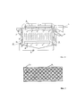
на фиг. 1 - изображено устройство электрофлотационной очистки водных растворов.in FIG. 1 - shows a device for electroflotation purification of aqueous solutions.
на фиг. 2 - изображены блоки ромбовидных ячеек.in FIG. 2 - blocks of diamond-shaped cells are shown.
Устройство электрофлотационной очистки водных растворов содержит корпус 1 с камерой напорной флотации 9, камерой электрофлотации 10, скребковый механизм 6. Камера напорной флотации 9 содержит прикрепленную к ней перфорированную трубу 4 и внешний сатуратор 3. Камера электрофлотации 10 содержит четное количество блоков электродов 2, выполненных преимущественно из платинированного титана или из нержавеющей стали, на которые через токовводы 5 подается постоянное напряжение, над блоками электродов 2 расположены блоки ромбовидных ячеек 8. Пространство между корпусом 1 и ромбовидными ячейками 8 не забивается загрязняющими веществами, в отличие от использования прямоугольных ячеек. Для удаления флотошлама, предусмотрен навесной скребковый механизм 6, который сгребает флотошлам в приемный карман 7.The electroflotation purification device for aqueous solutions comprises a
Часть очищенной воды из камеры электрофлотации 10, через патрубок 14 поступает на внешний сатуратор 3 для насыщения воды воздухом, а затем через отверстия перфорированной трубы 4 в камеру напорной флотации 9.Part of the purified water from the
Работа устройства.The operation of the device.
Устройство электрофлотационной очистки водных растворов заполняют чистой водой, включают внешний сатуратор 3, подают напряжение на блоки электродов 2, в камере напорной флотации через отверстия перфорированной трубы 4 выделяется растворенный воздух в виде мелких пузырьков с размерами 100 мкм, обеспечивая режим напорной флотации. Режим течения жидкости в камере напорной флотации 9 турбулентный в восходящем потоке. Входной поток очищаемой жидкости через входной патрубок 11 подают в камеру напорной флотации 9. Частицы загрязнений размерами не менее 100 мкм в результате прилипания к ним пузырьков воздуха приобретают плавучесть и всплывают на поверхность жидкости и извлекается уже на этом этапе очитки.The electroflotation purification device for aqueous solutions is filled with pure water, an
Из камеры напорной флотации 9 поток жидкости поступает в камеру электрофлотации 10, равномерно распределяясь в нисходящем потоке через ромбовидные ячейки 8. Пространство между корпусом 1 и ромбовидными ячейками 8 не забивается загрязняющими веществами, в отличие от использования прямоугольных ячеек.From the
В камере электрофлотации 10 осуществляется режим электрофлотации при подаче на блоки электродов 2 через токовводы 5 постоянного напряжения. В результате электролиза воды на блоках электродов 2 выделяются газы, которые в виде мельчайших пузырьков размерами 10 мкм всплывают на поверхность воды, удерживая слой флотошлама, который с помощью скребкового механизма 6 удаляют в приемный карман 7 для флотошлама. Флотошлам выводится из электрофлотатора через патрубок для выхода флотошлама 12 самотеком.In the
Нисходящая скорость движения воды в камере электрофлотации 10 ограничена скоростью всплытия пузырьков газов электролиза 3 мм/с. Флотирующими газами являются газы электролиза воды, образующиеся при подаче на блоки электродов постоянного напряжения при эффективной плотности тока не более 20 мА/см2. Размер микропузырьков газов электролиза позволяет извлекать более мелкие частицы по сравнению с методом напорной флотации с одновременным обеззараживанием очищаемой воды. Режим течения жидкости ламинарный с нисходящим потоком. Очищенная вода выходит через патрубок для выхода очищенной воды 13. Часть очищенной воды через патрубок 14 поступает во внешний сатуратор 3, где происходит насыщение воды воздухом, а затем через отверстия перфорированной трубы 4 в камеру напорной флотации 9.The downward velocity of water in the
Использование заявляемого устройства позволит исключить зарастание межэлектродного пространства загрязняющими веществами и при этом повысить качество очистки жидкости.The use of the inventive device will eliminate the overgrowth of the interelectrode space with contaminants and at the same time improve the quality of liquid purification.
Claims (1)
Priority Applications (1)
| Application Number | Priority Date | Filing Date | Title |
|---|---|---|---|
| RU2018132065A RU2699503C1 (en) | 2018-09-06 | 2018-09-06 | Device for electro-flotation purification of aqueous solutions |
Applications Claiming Priority (1)
| Application Number | Priority Date | Filing Date | Title |
|---|---|---|---|
| RU2018132065A RU2699503C1 (en) | 2018-09-06 | 2018-09-06 | Device for electro-flotation purification of aqueous solutions |
Publications (1)
| Publication Number | Publication Date |
|---|---|
| RU2699503C1 true RU2699503C1 (en) | 2019-09-05 |
Family
ID=67851921
Family Applications (1)
| Application Number | Title | Priority Date | Filing Date |
|---|---|---|---|
| RU2018132065A RU2699503C1 (en) | 2018-09-06 | 2018-09-06 | Device for electro-flotation purification of aqueous solutions |
Country Status (1)
| Country | Link |
|---|---|
| RU (1) | RU2699503C1 (en) |
Cited By (1)
| Publication number | Priority date | Publication date | Assignee | Title |
|---|---|---|---|---|
| RU213437U1 (en) * | 2022-05-20 | 2022-09-12 | Евгений Викторович Крашенников | Device for electroflotation wastewater treatment |
Citations (6)
| Publication number | Priority date | Publication date | Assignee | Title |
|---|---|---|---|---|
| SU1100238A1 (en) * | 1983-02-25 | 1984-06-30 | Пермский политехнический институт | Horizontal electrical flotator |
| SU1286624A1 (en) * | 1985-01-10 | 1987-01-30 | Институт биохимии АН БССР | Electric flotation plant for isolating biomass from cultivation fluid |
| WO1994011308A1 (en) * | 1992-11-17 | 1994-05-26 | Turun Ekovesi Oy | Method and device for purification of aqueous solutions by electroflotation |
| RU34162U1 (en) * | 2003-07-21 | 2003-11-27 | Общество с ограниченной ответственностью "ЭКО-С" | Pressure flotation unit |
| RU79547U1 (en) * | 2007-03-09 | 2009-01-10 | Закрытое акционерное общество "Техносфера" | FLOTATION WATER TREATMENT DEVICE |
| RU2459667C2 (en) * | 2011-04-13 | 2012-08-27 | Михаил Владимирович Бородин | Electric flotator with device for conversion of fluid turbulent flow into laminar flow |
-
2018
- 2018-09-06 RU RU2018132065A patent/RU2699503C1/en active
Patent Citations (6)
| Publication number | Priority date | Publication date | Assignee | Title |
|---|---|---|---|---|
| SU1100238A1 (en) * | 1983-02-25 | 1984-06-30 | Пермский политехнический институт | Horizontal electrical flotator |
| SU1286624A1 (en) * | 1985-01-10 | 1987-01-30 | Институт биохимии АН БССР | Electric flotation plant for isolating biomass from cultivation fluid |
| WO1994011308A1 (en) * | 1992-11-17 | 1994-05-26 | Turun Ekovesi Oy | Method and device for purification of aqueous solutions by electroflotation |
| RU34162U1 (en) * | 2003-07-21 | 2003-11-27 | Общество с ограниченной ответственностью "ЭКО-С" | Pressure flotation unit |
| RU79547U1 (en) * | 2007-03-09 | 2009-01-10 | Закрытое акционерное общество "Техносфера" | FLOTATION WATER TREATMENT DEVICE |
| RU2459667C2 (en) * | 2011-04-13 | 2012-08-27 | Михаил Владимирович Бородин | Electric flotator with device for conversion of fluid turbulent flow into laminar flow |
Cited By (2)
| Publication number | Priority date | Publication date | Assignee | Title |
|---|---|---|---|---|
| RU213437U1 (en) * | 2022-05-20 | 2022-09-12 | Евгений Викторович Крашенников | Device for electroflotation wastewater treatment |
| RU2826356C1 (en) * | 2024-04-24 | 2024-09-09 | Федеральное государственное бюджетное образовательное учреждение высшего образования "Санкт-Петербургский государственный аграрный университет" (ФГБОУ ВО СПбГАУ) | Electroflotation unit |
Similar Documents
| Publication | Publication Date | Title |
|---|---|---|
| RU2008142175A (en) | WASTE WATER TREATMENT METHOD | |
| KR101852179B1 (en) | Flotation device using high efficiency tank for dissolving a gases into liquids | |
| KR101679739B1 (en) | Flotation device using high efficiency tank for dissolving a gases into liquids | |
| JPH0839074A (en) | Method and apparatus for treating industrial wastewater by electrolysis | |
| KR101977787B1 (en) | Filtering Apparatus Containing Floating Media and Filtering Method | |
| US10822255B2 (en) | Water treatment apparatus using underwater plasma discharge and water treatment system including same | |
| CN115594262A (en) | Electric field separation device and oil-water mixture treatment equipment | |
| US20100224506A1 (en) | Process and apparatus for complex treatment of liquids | |
| RU2699503C1 (en) | Device for electro-flotation purification of aqueous solutions | |
| JPS5850560B2 (en) | Equipment for electrochemically purifying contaminated liquids | |
| RU173849U1 (en) | PLASMA-CHEMICAL REACTOR FOR LIQUID PROCESSING OF BARRIER DISCHARGE | |
| JP2000334462A (en) | Packed bed type electrochemical water treating device and method therefor | |
| CN110228840B (en) | An electrical floating wastewater treatment system and an electrical floating wastewater treatment method | |
| RU2339583C1 (en) | Device for electrochemical water purification | |
| RU2360869C2 (en) | Device for electrolytic processing of oil-containing waters | |
| CN210559556U (en) | An electrical floating wastewater treatment system | |
| RU2853498C1 (en) | Laboratory electroflotation installation | |
| RU142081U1 (en) | ELECTROSORPTION FILTER | |
| JP5294555B2 (en) | Sewage treatment equipment | |
| RU213437U1 (en) | Device for electroflotation wastewater treatment | |
| RU2341464C2 (en) | Electrochemical method of purifying oily water effluents and device to this end | |
| CN113443758A (en) | Full-quantitative pretreatment device, treatment system and treatment method for landfill leachate | |
| RU2806771C1 (en) | Method for aeroseparation liquid purification and device for its implementation | |
| JPS5850559B2 (en) | Device for electrochemical purification of contaminated liquids | |
| RU2333893C1 (en) | Water treating device |