RU2690708C2 - Compensation accelerometer - Google Patents
Compensation accelerometer Download PDFInfo
- Publication number
- RU2690708C2 RU2690708C2 RU2017139165A RU2017139165A RU2690708C2 RU 2690708 C2 RU2690708 C2 RU 2690708C2 RU 2017139165 A RU2017139165 A RU 2017139165A RU 2017139165 A RU2017139165 A RU 2017139165A RU 2690708 C2 RU2690708 C2 RU 2690708C2
- Authority
- RU
- Russia
- Prior art keywords
- coil
- pendulum
- accelerometer
- torque sensor
- elastic
- Prior art date
Links
Images
Classifications
-
- G—PHYSICS
- G01—MEASURING; TESTING
- G01P—MEASURING LINEAR OR ANGULAR SPEED, ACCELERATION, DECELERATION, OR SHOCK; INDICATING PRESENCE, ABSENCE, OR DIRECTION, OF MOVEMENT
- G01P15/00—Measuring acceleration; Measuring deceleration; Measuring shock, i.e. sudden change of acceleration
- G01P15/02—Measuring acceleration; Measuring deceleration; Measuring shock, i.e. sudden change of acceleration by making use of inertia forces using solid seismic masses
- G01P15/08—Measuring acceleration; Measuring deceleration; Measuring shock, i.e. sudden change of acceleration by making use of inertia forces using solid seismic masses with conversion into electric or magnetic values
- G01P15/13—Measuring acceleration; Measuring deceleration; Measuring shock, i.e. sudden change of acceleration by making use of inertia forces using solid seismic masses with conversion into electric or magnetic values by measuring the force required to restore a proofmass subjected to inertial forces to a null position
Abstract
Description
Изобретение относится к измерительной технике и может быть использовано в акселерометрах с упругим подвесом чувствительного элемента.The invention relates to measuring equipment and can be used in accelerometers with an elastic suspension of a sensitive element.
Известен акселерометр [1], содержащий корпус с подвешенным в нем на торсионах маятником, связанным через усилитель с датчиком момента.A known accelerometer [1], comprising a housing with a pendulum suspended in it on torsions, connected through an amplifier with a torque sensor.
Недостатком акселерометра является зависимость точности прибора от прогиба упругих элементов при действии линейного ускорения по оси чувствительности, т.к. точность прибора тем выше, чем больше соотношение полезного момента от электрических пружин к вредному упругому моменту от торсионов.The disadvantage of the accelerometer is the dependence of the accuracy of the device on the deflection of elastic elements under the action of linear acceleration along the sensitivity axis, since the accuracy of the device is the higher, the greater the ratio of the useful moment from the electric springs to the harmful elastic moment from the torsions.
Наиболее близким по техническому решению является компенсационный акселерометр [2], содержащий маятник, подвешенный на растяжках, являющихся токопроводами, первая растяжка жестко прикреплена к корпусу, вторая растяжка прикреплена к втулке, расположенной во фланце, расположенном внутри корпуса, при этом фланец и втулка жестко соединены между собой термокомпенсирующим элементом, датчик угла, выход которого соединен с усилителем, магнитоэлектрический датчик момента, содержащий катушку, вход которой соединен с выходом усилителя, магнитную систему.The closest technical solution is a compensating accelerometer [2], containing a pendulum suspended from stretch marks that are conductor lines, the first stretch is rigidly attached to the body, the second stretch is attached to the sleeve located in the flange located inside the case, while the flange and sleeve are rigidly connected between themselves a temperature compensating element, an angle sensor, the output of which is connected to an amplifier, a magnetoelectric torque sensor containing a coil, the input of which is connected to the output of the amplifier, a magnetic system.
Недостатком компенсационного акселерометра является низкая точность измерения.The disadvantage of the compensation accelerometer is low measurement accuracy.
Технический результат заявленного изобретения заключается в повышении точности компенсационного акселерометра.The technical result of the claimed invention is to improve the accuracy of the compensation accelerometer.
Задача, на решение которой направлено заявленное изобретение, заключается в уменьшении прогиба упругого подвеса компенсационного акселерометра при воздействии линейного ускорения.The problem to which the claimed invention is directed is to reduce the deflection of the elastic suspension of the compensation accelerometer when exposed to linear acceleration.
Поставленная задача решается за счет того, что компенсационный акселерометр, содержащий корпус, магнитоэлектрический датчик момента, катушка которого одновременно является маятником, консольно подвешенным на упругих элементах, выполняющих так же роль токоподводов, согласно изобретению, содержит магнитную систему, в зазоре которой находится сторона катушки датчика момента, расположенная вдоль оси подвеса.The problem is solved due to the fact that the compensation accelerometer, comprising a housing, a magnetoelectric torque sensor, the coil of which is simultaneously a pendulum, is suspended from elastic elements that also act as current leads according to the invention, contains a magnetic system, in the gap of which is the side of the sensor coil moment located along the axis of suspension.
Отличительным признаком заявленного изобретения является введение в состав компенсационного акселерометра дополнительной магнитной системы, позволяющей уменьшить прогиб упругого подвеса компенсационного акселерометра за счет выталкивающей силы, формируемой током.A distinctive feature of the claimed invention is the introduction of the compensation accelerometer additional magnetic system, which allows to reduce the deflection of the elastic suspension compensation accelerometer due to the buoyant force generated by the current.
Пример компенсационного акселерометра.An example of a compensation accelerometer.
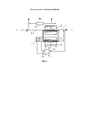
На фиг. 1 изображена электрокинематическая схема компенсационного акселерометра, содержащего маятник (1), являющийся одновременно катушкой магнитоэлектрического датчика момента, подвешенный на упругих элементах (2) и (3), являющихся токопроводящими элементами, жестко прикрепленных к корпусу (4).FIG. 1 shows an electrocinematic scheme of a compensation accelerometer comprising a pendulum (1), which is simultaneously a coil of a magnetoelectric torque sensor, suspended on elastic elements (2) and (3), which are conductive elements rigidly attached to the body (4).
Как показано на фиг. 1, поворот маятника (1) вокруг оси Х-Х фиксируется датчиком угла (5), соединенным с входом усилителя (6). Выход усилителя (6) соединен посредством упругого элемента (3) с катушкой датчика момента, содержащего магнит (7). Под действием линейного ускорения, направленного перпендикулярно плоскости фигуры, маятник (1) отклоняется от исходного положения, отклонение регистрируется датчиком угла (5) и через усилитель (6) в виде определенной величины тока подается на катушку магнитоэлектрического датчика момента. Выходное напряжение снимается с резистора (8), соединенного с входом катушки магнитоэлектрического датчика момента посредством упругого элемента (2).As shown in FIG. 1, the rotation of the pendulum (1) around axis X-X is detected by an angle sensor (5) connected to the input of the amplifier (6). The output of the amplifier (6) is connected by means of an elastic element (3) to a coil of a torque sensor containing a magnet (7). Under the action of linear acceleration, directed perpendicular to the plane of the figure, the pendulum (1) deviates from the initial position, the deviation is recorded by the angle sensor (5) and through the amplifier (6) as a certain amount of current is applied to the coil of the magnetoelectric torque sensor. The output voltage is removed from the resistor (8) connected to the input of the coil of the magnetoelectric torque sensor by means of an elastic element (2).
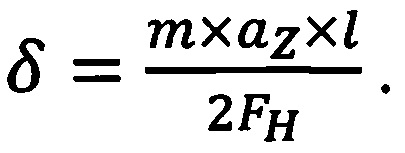
Одновременно с угловым отклонением маятника (1) при воздействии линейного ускорения происходит плоскопараллельное перемещение катушки магнитоэлектрического датчика момента. Величину плоскопараллельного перемещения можно определить по формуле:Simultaneously with the angular deviation of the pendulum (1) under the influence of linear acceleration, a plane-parallel movement of the coil of the magnetoelectric torque sensor occurs. The value of the plane-parallel movement can be determined by the formula:

где:Where:
FH - сила предварительного натяжения упругого элемента;F H - pre-tension force of the elastic element;
Р - распределенная нагрузка;P - distributed load;
![]()
![]()
δ - прогиб (величина плоскопараллельного перемещения).δ - deflection (the value of plane-parallel movement).
![]()
![]()
где:Where:
m - масса подвижной части;m is the mass of the moving part;
a Z - действующее ускорение, a Z - effective acceleration
Отсюда:From here:
![]()
![]()
иand
Прогиб меняет упругие свойства упругих элементов (2) и (3), от которых зависит нулевой сигнал акселерометра. Чем выше отношение полезного момента от датчика момента к паразитному упругому моменту от упругих элементов (2) и (3), тем точнее компенсационный акселерометр.The deflection changes the elastic properties of the elastic elements (2) and (3), on which the zero signal of the accelerometer depends. The higher the ratio of the useful moment from the moment sensor to the parasitic elastic moment from the elastic elements (2) and (3), the more accurate the compensation accelerometer.
При подаче на катушку тока возникает момент, действующий на участок катушки магнитоэлектрического датчика момента, находящийся в рабочем зазоре магнита (7). Действующий момент вычисляют по формуле:When a current is applied to the coil, a moment arises that acts on the coil portion of the magnetoelectric torque sensor located in the working gap of the magnet (7). Actual moment is calculated by the formula:
![]()
![]()
где:Where:
Bl B l
- индукция в рабочем зазоре магнитной системы,- induction in the working gap of the magnetic system,
![]()
![]()
![]()
![]()
w - число витков катушки магнитоэлектрического датчика момента,w is the number of turns of the coil of the magnetoelectric torque sensor,
![]()
![]()
Этот же ток протекает по участку катушки магнитоэлектрического датчика момента, расположенному в рабочем зазоре магнита (9), что приводит к формированию выталкивающей силы, которую вычисляют по формуле:The same current flows through the coil section of the magnetoelectric torque sensor located in the working gap of the magnet (9), which leads to the formation of a buoyancy force, which is calculated by the formula:
![]()
![]()
В2 In 2
где: - индукция в рабочем зазоре магнитной системы (9).where: - induction in the working gap of the magnetic system (9).
Использование дополнительного магнита (9), расположенного вдоль оси упругого подвеса, позволяет уменьшить прогиб упругого подвеса компенсационного акселерометра при воздействии линейного ускорения и, следовательно, повысить точность компенсационного акселерометра за счет повышения отношения полезного момента от маятника к паразитному упругому моменту от упругих элементов.The use of an additional magnet (9) located along the axis of the elastic suspension reduces the deflection of the elastic suspension of the compensation accelerometer when exposed to linear acceleration and, therefore, improves the accuracy of the compensation accelerometer by increasing the ratio of the useful moment from the pendulum to the parasitic elastic moment from the elastic elements.
Источники информации:Information sources:
1. Авторское свидетельство СССР №980008, МПК G01P 15/10, приоритет от 05.05.1980 г. 1. USSR author's certificate No. 980008, IPC G01P 15/10, priority of 05/05/1980
2. Авторское свидетельство СССР №1623434, МПК G01P 21/00, приоритет от 09.11.1988 г. 2. USSR author's certificate No. 1623434, IPC G01P 21/00, priority date of 11/09/1988
Claims (1)
Priority Applications (1)
| Application Number | Priority Date | Filing Date | Title |
|---|---|---|---|
| RU2017139165A RU2690708C2 (en) | 2017-11-10 | 2017-11-10 | Compensation accelerometer |
Applications Claiming Priority (1)
| Application Number | Priority Date | Filing Date | Title |
|---|---|---|---|
| RU2017139165A RU2690708C2 (en) | 2017-11-10 | 2017-11-10 | Compensation accelerometer |
Publications (3)
| Publication Number | Publication Date |
|---|---|
| RU2017139165A3 RU2017139165A3 (en) | 2019-05-13 |
| RU2017139165A RU2017139165A (en) | 2019-05-13 |
| RU2690708C2 true RU2690708C2 (en) | 2019-06-05 |
Family
ID=66548663
Family Applications (1)
| Application Number | Title | Priority Date | Filing Date |
|---|---|---|---|
| RU2017139165A RU2690708C2 (en) | 2017-11-10 | 2017-11-10 | Compensation accelerometer |
Country Status (1)
| Country | Link |
|---|---|
| RU (1) | RU2690708C2 (en) |
Citations (5)
| Publication number | Priority date | Publication date | Assignee | Title |
|---|---|---|---|---|
| RU2291450C1 (en) * | 2005-05-26 | 2007-01-10 | Федеральное государственное унитарное предприятие "Научно-производственный центр автоматики и приборостроения им. Академика Н.А. Пилюгина" (ФГУП "НПЦАП") | Compensation pendulum type accelerometer |
| RU111302U1 (en) * | 2010-07-05 | 2011-12-10 | ФГУП "Центр эксплуатации объектов наземной космической инфраструктуры" | ACCELEROMETER |
| US8150651B2 (en) * | 2008-06-11 | 2012-04-03 | Trimble Navigation Limited | Acceleration compensated inclinometer |
| RU2543708C1 (en) * | 2013-07-31 | 2015-03-10 | Открытое акционерное общество "Арзамасский приборостроительный завод имени П.И. Пландина"-ОАО "АПЗ" | Compensation pendulous accelerometer |
| RU2559154C2 (en) * | 2013-09-25 | 2015-08-10 | Федеральное государственное унитарное предприятие "Научно-производственный центр автоматики и приборостроения имени академика Н.А. Пилюгина" (ФГУП "НПЦАП") | Compensation-type pendulum accelerometer |
-
2017
- 2017-11-10 RU RU2017139165A patent/RU2690708C2/en active
Patent Citations (5)
| Publication number | Priority date | Publication date | Assignee | Title |
|---|---|---|---|---|
| RU2291450C1 (en) * | 2005-05-26 | 2007-01-10 | Федеральное государственное унитарное предприятие "Научно-производственный центр автоматики и приборостроения им. Академика Н.А. Пилюгина" (ФГУП "НПЦАП") | Compensation pendulum type accelerometer |
| US8150651B2 (en) * | 2008-06-11 | 2012-04-03 | Trimble Navigation Limited | Acceleration compensated inclinometer |
| RU111302U1 (en) * | 2010-07-05 | 2011-12-10 | ФГУП "Центр эксплуатации объектов наземной космической инфраструктуры" | ACCELEROMETER |
| RU2543708C1 (en) * | 2013-07-31 | 2015-03-10 | Открытое акционерное общество "Арзамасский приборостроительный завод имени П.И. Пландина"-ОАО "АПЗ" | Compensation pendulous accelerometer |
| RU2559154C2 (en) * | 2013-09-25 | 2015-08-10 | Федеральное государственное унитарное предприятие "Научно-производственный центр автоматики и приборостроения имени академика Н.А. Пилюгина" (ФГУП "НПЦАП") | Compensation-type pendulum accelerometer |
Also Published As
| Publication number | Publication date |
|---|---|
| RU2017139165A3 (en) | 2019-05-13 |
| RU2017139165A (en) | 2019-05-13 |
Similar Documents
| Publication | Publication Date | Title |
|---|---|---|
| US2869851A (en) | Apparatus adapted to measure accelerations and inclinations | |
| JP2007256266A (en) | Compensated accelerometer with optical angle detection | |
| US2607223A (en) | Apparatus for measuring rate of fluid flow | |
| US2888256A (en) | Accelerometers | |
| RU2690708C2 (en) | Compensation accelerometer | |
| JP5090266B2 (en) | Servo type accelerometer and acceleration measuring device | |
| EP1815257B1 (en) | Wind and water speed and direction measurement device | |
| RU2313100C1 (en) | Accelerometer | |
| RU2559154C2 (en) | Compensation-type pendulum accelerometer | |
| RU2485524C2 (en) | Accelerometer | |
| JP2021105604A (en) | Position detecting signal correction method and position detecting device | |
| RU111302U1 (en) | ACCELEROMETER | |
| KR101264771B1 (en) | Accelerometer with silicon pendulum assembly which improves scale factor linearity under high-g acceleration | |
| RU2193209C1 (en) | Compensation accelerometer | |
| RU2758892C1 (en) | Compensation pendulum accelerometer | |
| SU1700484A1 (en) | Device for measurement of accelerations | |
| RU2514150C1 (en) | Accelerometer | |
| RU140588U1 (en) | MAGNETO-LIQUID DEVICE FOR TILT ANGLE DETERMINATION | |
| RU2199754C2 (en) | Device for transforming inertial data | |
| RU2509307C1 (en) | Linear accelerometer | |
| SU980008A1 (en) | Accelerometer | |
| RU2450278C2 (en) | Microsystem accelerometre | |
| RU2545469C1 (en) | Compensation accelerometer | |
| RU193692U1 (en) | Magnetic compensator for fiber optic gyroscope | |
| SU901915A1 (en) | Accelerometer |