RU2689286C2 - Oxygen sensor comprising a large diameter optical fiber with a coated tip - Google Patents
Oxygen sensor comprising a large diameter optical fiber with a coated tip Download PDFInfo
- Publication number
- RU2689286C2 RU2689286C2 RU2016135524A RU2016135524A RU2689286C2 RU 2689286 C2 RU2689286 C2 RU 2689286C2 RU 2016135524 A RU2016135524 A RU 2016135524A RU 2016135524 A RU2016135524 A RU 2016135524A RU 2689286 C2 RU2689286 C2 RU 2689286C2
- Authority
- RU
- Russia
- Prior art keywords
- oxygen
- optical fiber
- dye
- fluorophores
- sensor
- Prior art date
Links
Images


Classifications
-
- G—PHYSICS
- G01—MEASURING; TESTING
- G01N—INVESTIGATING OR ANALYSING MATERIALS BY DETERMINING THEIR CHEMICAL OR PHYSICAL PROPERTIES
- G01N21/00—Investigating or analysing materials by the use of optical means, i.e. using sub-millimetre waves, infrared, visible or ultraviolet light
- G01N21/75—Systems in which material is subjected to a chemical reaction, the progress or the result of the reaction being investigated
- G01N21/77—Systems in which material is subjected to a chemical reaction, the progress or the result of the reaction being investigated by observing the effect on a chemical indicator
- G01N21/7703—Systems in which material is subjected to a chemical reaction, the progress or the result of the reaction being investigated by observing the effect on a chemical indicator using reagent-clad optical fibres or optical waveguides
- G01N2021/7706—Reagent provision
- G01N2021/772—Tip coated light guide
-
- G—PHYSICS
- G01—MEASURING; TESTING
- G01N—INVESTIGATING OR ANALYSING MATERIALS BY DETERMINING THEIR CHEMICAL OR PHYSICAL PROPERTIES
- G01N21/00—Investigating or analysing materials by the use of optical means, i.e. using sub-millimetre waves, infrared, visible or ultraviolet light
- G01N21/75—Systems in which material is subjected to a chemical reaction, the progress or the result of the reaction being investigated
- G01N21/77—Systems in which material is subjected to a chemical reaction, the progress or the result of the reaction being investigated by observing the effect on a chemical indicator
- G01N21/7703—Systems in which material is subjected to a chemical reaction, the progress or the result of the reaction being investigated by observing the effect on a chemical indicator using reagent-clad optical fibres or optical waveguides
- G01N2021/7706—Reagent provision
- G01N2021/773—Porous polymer jacket; Polymer matrix with indicator
Abstract
Description
Настоящее изобретение относится к датчику кислорода и более конкретно к датчику кислорода для использования в авиационных применениях, и более конкретно в применениях, относящихся к топливным бакам или модулям отделения воздуха.The present invention relates to an oxygen sensor and more specifically to an oxygen sensor for use in aviation applications, and more specifically in applications related to fuel tanks or air separation modules.
Настоящее изобретение обеспечивает совершенствование измерения концентрации кислорода. Данное изобретение будет особенно полезно в измерении концентрации кислорода в незаполненном объеме топливного бака летательного аппарата или в модулях отделения воздуха.The present invention provides improved measurement of oxygen concentration. This invention will be particularly useful in measuring the oxygen concentration in an empty volume of an aircraft fuel tank or in air separation modules.
Известно использование гашения флуоресценции для индикации наличия некоторых соединений, представляющих интерес. Флуоресцентный материал излучает свет c определенной длиной волны и интенсивностью, который имеет определенное время жизни излучения, после возбуждения определенной длиной волны, которая меньше, чем излучаемая длина волны. Интенсивность и время жизни излучения зависят от концентрации кислорода, контактирующего с флуоресцентным материалом. Когда концентрация кислорода увеличивается, интенсивность и время жизни флуоресцентного излучения уменьшаются, и эти увеличение и уменьшение прямо пропорциональны друг другу.It is known to use fluorescence quenching to indicate the presence of some compounds of interest. Fluorescent material emits light with a specific wavelength and intensity, which has a certain radiation lifetime, after excitation of a specific wavelength that is less than the radiated wavelength. The intensity and lifetime of the radiation depends on the concentration of oxygen in contact with the fluorescent material. When the oxygen concentration increases, the intensity and lifetime of the fluorescent radiation decreases, and these increases and decreases are directly proportional to each other.
Датчики, используемые внутри топливных баков, содержат поверхность флуоресцентного материала, которая подвергается воздействию среды топливного бака. Уменьшение интенсивности и времени жизни излучения флуоресцентного материала при наличии кислорода обеспечивает прямое измерение концентрации кислорода около поверхности датчика. Флуоресцентное излучение материала, который возбужден электромагнитным способом, уменьшается прямо пропорционально концентрации соединений, представляющих интерес. Материалы, такие как платина-тетракис-пентафторфенил-порфирин и платина-октаэтилпорфирин, используются в качестве материалов, чувствительных к газообразному кислороду. Однако среда топливного бака является агрессивной и может вызывать деградацию флуоресцентного материала. Эта деградация материала приводит к уменьшению интенсивности и изменениям времени жизни флуоресцентного излучения, и это может быть неверно интерпретировано как более высокий уровень кислорода.The sensors used inside the fuel tanks contain the surface of a fluorescent material that is exposed to the environment of the fuel tank. Reducing the intensity and lifetime of the fluorescent material in the presence of oxygen provides a direct measurement of the oxygen concentration near the sensor surface. The fluorescent radiation of a material that is excited by an electromagnetic method decreases in direct proportion to the concentration of the compounds of interest. Materials such as platinum-tetrakis-pentafluorophenyl-porphyrin and platinum-octaethylporphyrin are used as materials sensitive to oxygen gas. However, the fuel tank environment is aggressive and may cause degradation of the fluorescent material. This degradation of the material leads to a decrease in the intensity and changes in the lifetime of the fluorescent radiation, and this may be incorrectly interpreted as a higher level of oxygen.
Процесс флуоресцентного излучения может быть обобщен следующим образом:The process of fluorescent radiation can be summarized as follows:
Возбуждение: L+ hν1=L* (уравнение 1)Excitation: L + hν 1 = L * (Equation 1)
Флуоресценция: L*= L+hν2 (уравнение 2)Fluorescence: L * = L + hν 2 (Equation 2)
Гашение: L*+O2=L+O2* (уравнение 3)Cancellation: L * + O 2 = L + O 2 * (Equation 3)
Уравнение 1 отображает процесс электромагнитного возбуждения флуорофора фотоном с энергией hν1. Уравнение 2 отображает излучение фотона с энергией hν2, в тех случаях, когда возбужденный флуорофор L* возвращается в невозбужденное состояние L и, причем, hν2 < hν1. При наличии кислорода, флуорофор передает энергию молекуле кислорода при столкновении, как это показано посредством уравнения 3. Эта передача энергии не испускает фотон в процессе, который определяют как гашение. Гашение возбужденного флуорофора молекулой кислорода приводит к уменьшению общей интенсивности и времени жизни излучения. Именно этот механизм, который обеспечил возможность разработки оптического датчика кислорода. Датчики нашли конкретное применение в авиакосмических топливных баках, но было обнаружено, что, когда датчик подвергается воздействию жидкого топлива, чувствительный к кислороду материал деградирует. Также, когда флуоресцентный материал подвергается воздействию топлива в баке, флуорофор может экранироваться молекулами углеводородов в топливе. Это взаимодействие может приводить к фото-обесцвечиванию, которое может приводить к необратимой деградации флуорофора. Если флуорофор и кислород не взаимодействуют, то тогда общая интенсивность и время жизни излучения увеличиваются. Это увеличение может быть неверно интерпретировано в качестве пониженной концентрации кислорода. Также будет необходимо калибровать или сравнивать с эталоном излучение от чувствительного к кислороду флуорофора.Equation 1 represents the process of electromagnetic excitation of a fluorophore by a photon with an energy of hν1. Equation 2 displays the radiation of a photon with energy hν 2, in cases when the excited fluorophore L * returns to the unexcited state L and, moreover, hν 2 < hν 1. In the presence of oxygen, the fluorophore transfers energy to the oxygen molecule in a collision, as shown by Equations 3. This energy transfer does not emit a photon in a process that is defined as quenching. The quenching of an excited fluorophore by an oxygen molecule leads to a decrease in the overall intensity and lifetime of the radiation. It is this mechanism that made it possible to develop an optical oxygen sensor. Sensors have found particular application in aerospace fuel tanks, but it has been found that when the sensor is exposed to liquid fuel, the material that is sensitive to oxygen degrades. Also, when the fluorescent material is exposed to fuel in the tank, the fluorophore can be shielded by hydrocarbon molecules in the fuel. This interaction can lead to photo-bleaching, which can lead to irreversible degradation of the fluorophore. If the fluorophore and oxygen do not interact, then the total intensity and lifetime of the radiation increase. This increase may be incorrectly interpreted as a reduced oxygen concentration. It will also be necessary to calibrate or compare with the standard radiation from an oxygen-sensitive fluorophore.
Настоящее изобретение направлено на преодоление проблем уровня техники посредством обеспечения датчика кислорода, включающего в себя чувствительный к кислороду флуоресцентный материал, включающий в себя сочетание: чувствительного к кислороду красителя и нечувствительного к кислороду красителя, причем оба красителя являются флуорофорами. Нечувствительный к кислороду краситель может быть кремний-октаэтилпорфирином. Чувствительный к кислороду краситель может быть платина-тетракис-пентафторфенилпорфирином или платина-октаэтилпорфирином. Эти два красителя могут быть диспергированы в полимерной матрице, например, полидиметилсилоксановой матрице. В качестве альтернативы, материал может быть изготовлен с использованием золь-гель-ксерогель процесса. С использованием этой технологии, становится возможным диспергировать материал в стойкой к топливу и проницаемой для кислорода фторосиликоновой резине.The present invention aims to overcome the problems of the prior art by providing an oxygen sensor that includes an oxygen sensitive fluorescent material comprising a combination of: an oxygen sensitive dye and an oxygen insensitive dye, both dye being fluorophores. The oxygen-insensitive dye may be silicon-octaethylporphyrin. The oxygen sensitive dye may be platinum-tetrakis-pentafluorophenylporphyrin or platinum-octaethylporphyrin. These two dyes can be dispersed in a polymer matrix, for example, a polydimethylsiloxane matrix. Alternatively, the material can be made using a sol-gel-xerogel process. Using this technology, it becomes possible to disperse the material in a fuel-resistant and oxygen-permeable fluorosilicone rubber.
Чувствительный к кислороду краситель и нечувствительный к кислороду краситель могут быть возбуждены одной и той же длиной волны. Каждый из этих красителей, в сравнении с другим красителем, излучает отличную длину волны, интенсивность, и его излучение имеет отличное время жизни. После взаимодействия с молекулами кислорода, интенсивность и время жизни излучения уменьшаются для чувствительного к кислороду красителя, в то время как интенсивность и время жизни излучения нечувствительного к кислороду красителя остаются неизменными.An oxygen sensitive dye and an oxygen insensitive dye can be excited by the same wavelength. Each of these dyes, in comparison with another dye, emits an excellent wavelength, intensity, and its radiation has an excellent lifetime. After interaction with oxygen molecules, the intensity and lifetime of the radiation decrease for the oxygen-sensitive dye, while the intensity and lifetime of the radiation of the oxygen-insensitive dye remain unchanged.
Датчик имеет наконечник, содержащий сочетание нечувствительного к кислороду красителя и чувствительного к кислороду красителя. Наконечник находится на конце волокна большого оптического диаметра. Другой конец волокна большого оптического диаметра выполнен с возможностью соединения с призмой или датчиками для разделения длин волн. Волокно большого диаметра размещено в трубке, предпочтительно, изготовленной из стали. Один конец трубки имеет резиновую мембрану и один или более вентиляционных клапанов, которые предотвращают взаимодействие жидкого топлива с флуорофорами, но которые допускают взаимодействие между флуорофорами и кислородом. Мембрана может быть изготовлена из любого подходящего материала, стойкого к авиакосмическим топливам и проницаемого для газообразного кислорода, например, фторосиликоновой резины, полидиметилсилоксана.The sensor has a tip containing a combination of an oxygen insensitive dye and an oxygen sensitive dye. The tip is located at the end of the fiber with a large optical diameter. The other end of the fiber of large optical diameter is made with the possibility of connection with a prism or sensors for the separation of wavelengths. A large-diameter fiber is placed in a tube, preferably made of steel. One end of the tube has a rubber membrane and one or more vent valves that prevent liquid fuel from interacting with fluorophores, but which allow interaction between fluorophores and oxygen. The membrane can be made of any suitable material that is resistant to aerospace fuels and permeable to gaseous oxygen, for example, fluorosilicone rubber, polydimethylsiloxane.
Устройство для передачи возбуждающего света и для приема излучения от чувствительного к кислороду флуоресцентного материала включает в себя оптическое волокно. Это волокно имеет, предпочтительно, большой диаметр. Устройство дополнительно включает в себя трихроичную призму и два фотодетектора или трехцветные датчики, такие как интегральные RGB-датчики. Трихроичная призма и два фотодетектора или трехцветные датчики, такие как интегральные RGB-датчики, разделяют три длины волны; длину волны возбуждения и длины волн излучения от каждого красителя. Интенсивность и время жизни преобразуются в пропорциональные токи. Управляемые током усилители напряжения используются для преобразования тока в напряжение (V1), которое пропорционально интенсивности или времени жизни излучения от нечувствительного к кислороду красителя, и напряжение (V2), которое пропорционально интенсивности или времени жизни излучения от чувствительного к кислороду красителя. Возбуждение является импульсным для того, чтобы измерять время жизни излучения. Как правило, время жизни флуоресценции находится между 70 и 100 мкс и контролируется в течение известного времени. Время жизни и интенсивность можно измерять совместно.A device for transmitting excitation light and for receiving radiation from an oxygen-sensitive fluorescent material includes an optical fiber. This fiber preferably has a large diameter. The device additionally includes a trichroic prism and two photodetectors or three-color sensors, such as integrated RGB sensors. A trichroic prism and two photodetectors or three-color sensors, such as integrated RGB sensors, share three wavelengths; excitation wavelength and radiation wavelength from each dye. Intensity and lifetime are converted into proportional currents. Current-controlled voltage amplifiers are used to convert current to voltage (V1), which is proportional to the intensity or lifetime of radiation from an oxygen insensitive dye, and voltage (V2), which is proportional to the intensity or lifetime of radiation from an oxygen-sensitive dye. The excitation is pulsed in order to measure the lifetime of the radiation. Typically, the fluorescence lifetime is between 70 and 100 μs and monitored for a certain time. Lifetime and intensity can be measured together.
Во время функционирования датчика, напряжения (V1 и V2) сравнивают друг с другом для заключения о характеристиках чувствительного к кислороду флуоресцентного материала. Когда уровень кислорода увеличивается, V2 уменьшается, а V1 остается неизменным. Если материал деградирует при отсутствии изменений в концентрации кислорода, то тогда V1 и V2 будут уменьшаться вместе. Характеристики материала, концентрация кислорода и чувствительность могут быть откалиброваны посредством отношения V1/V2. Это сравнение напряжений является эффективным при встроенной самопроверке.During sensor operation, the voltages (V1 and V2) are compared with each other to infer the characteristics of an oxygen sensitive fluorescent material. When the oxygen level increases, V2 decreases, and V1 remains unchanged. If the material is degraded in the absence of changes in oxygen concentration, then V1 and V2 will decrease together. Material characteristics, oxygen concentration and sensitivity can be calibrated using the V1 / V2 ratio. This voltage comparison is effective with an integrated self-test.
Настоящее изобретение описано со ссылкой на сопровождающие чертежи, на которых:The present invention is described with reference to the accompanying drawings, in which:
Фиг. 1 показывает зонд датчика, имеющий датчик согласно настоящему изобретению.FIG. 1 shows a probe probe having a sensor according to the present invention.
Фиг. 2 показывает датчик и средство для разделения длин волн излучения от флуорофоров и излучения возбуждения согласно настоящему изобретению.FIG. 2 shows a sensor and means for separating radiation wavelengths from fluorophores and excitation radiation in accordance with the present invention.
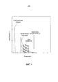
Фиг. 3 показывает пример флуоресцентного излучения от двух флуорофоров.FIG. 3 shows an example of fluorescent radiation from two fluorophores.
Фиг. 4 показывает окно известного времени, в котором измеряют время жизни излучения.FIG. 4 shows a window of a known time in which the radiation lifetime is measured.
Фиг 1 показывает зонд 20 датчика, который включает в себя волокно 22 большого диаметра, имеющее волоконный соединитель 24 для соединения волокна с трихроичной призмой или трехцветным датчиком. Волокно 22 большого диаметра имеет наконечник 26 (показанный более подробно в увеличенной области), который оканчивается в чувствительном к кислороду флуоресцентном материале 28, который включает в себя чувствительный к кислороду краситель и нечувствительный к кислороду краситель, причем оба эти красители являются флуорофорами. Волокно 22 большого диаметра размещено внутри трубки 30 для защиты. Трубка имеет вентиляционный клапан 32, соединяемый c ней, который включает в себя мембрану для предотвращения взаимодействия жидкого топлива и наконечника 28 с двумя флуорофорами.FIG. 1 shows a probe 20 of a sensor that includes a large-
Фиг. 2 показывает упрощенную версию зонда датчика, показанного на фиг. 1. Чувствительный к кислороду флуоресцентный материал 28 расположен на одном конце оптического волокна 22 большого диаметра. На другом конце оптического волокна 22 находится трихроичная призма 40. Фотоны направляются через призму 40 и передаются оптическим волокном 22 для возбуждения флуорофоров в наконечнике 28. Излучение от флуорофоров передается волокном 22 и проходит через трихроичную призму 40 для разделения трех длин волн, состоящих из длины волны возбуждения, длины волны излучения от чувствительного к кислороду красителя 36 и длины волны излучения от нечувствительного к кислороду красителя 38. Два фотодетектора (не показаны) используются для преобразования информации об интенсивности или времени жизни в пропорциональные токи I1 и I2. Затем ток преобразуется в напряжение посредством управляемых током усилителей напряжения.FIG. 2 shows a simplified version of the sensor probe shown in FIG. 1. The oxygen
Фиг. 3 показывает график энергии относительно интенсивности флуоресценции. Можно увидеть, что интенсивность излучения от чувствительного к кислороду красителя уменьшается, а концентрация кислорода увеличивается. Однако, интенсивность излучения от нечувствительного к кислороду красителя остается неизменной при изменении концентрации кислорода.FIG. 3 shows a graph of energy relative to fluorescence intensity. It can be seen that the intensity of the radiation from the oxygen-sensitive dye decreases and the oxygen concentration increases. However, the intensity of the radiation from the oxygen insensitive dye remains unchanged when the oxygen concentration changes.
Фиг. 4 показывает окно 50 измерения известного времени, в котором измеряют время жизни излучения. Общая интегральная интенсивность в окне 50 измерения обеспечивает измерение концентрации кислорода.FIG. 4 shows a measurement window 50 of a known time in which the radiation lifetime is measured. The total integrated intensity in the measurement window 50 provides measurement of the oxygen concentration.
Конструкция, аналогичная показанной и описанной конструкции датчика кислорода, может быть использована в применениях, относящихся к топливному баку и модулям отделения воздуха.A design similar to that shown and described design of an oxygen sensor can be used in applications related to a fuel tank and air separation modules.
Признаки, раскрытые в приведенном выше описании или в нижеследующей формуле изобретения, или на сопровождающих чертежах, выраженные в своих конкретных формах или с точки зрения средства для выполнения раскрытой функции, или способа достижения раскрытого результата, в соответствующих случаях, могут быть использованы для реализации настоящего изобретения в других их формах, отдельно или в любом сочетании таких признаков.The features disclosed in the above description or in the following claims, or in the accompanying drawings, expressed in their particular forms or in terms of means for performing the disclosed function, or a method for achieving the disclosed result, as appropriate, can be used to implement the present invention in their other forms, separately or in any combination of such signs.
Claims (19)
Applications Claiming Priority (5)
| Application Number | Priority Date | Filing Date | Title |
|---|---|---|---|
| GB1402734.6 | 2014-02-17 | ||
| GBGB1402734.6A GB201402734D0 (en) | 2014-02-17 | 2014-02-17 | Oxygen sensor |
| GBGB1416438.8A GB201416438D0 (en) | 2014-09-17 | 2014-09-17 | Oxygen sensor |
| GB1416438.8 | 2014-09-17 | ||
| PCT/EP2015/053328 WO2015121499A1 (en) | 2014-02-17 | 2015-02-17 | Oxygen sensor comprising a tip coated optical fibre with a large diameter |
Publications (3)
| Publication Number | Publication Date |
|---|---|
| RU2016135524A RU2016135524A (en) | 2018-03-22 |
| RU2016135524A3 RU2016135524A3 (en) | 2018-11-21 |
| RU2689286C2 true RU2689286C2 (en) | 2019-05-24 |
Family
ID=52472339
Family Applications (1)
| Application Number | Title | Priority Date | Filing Date |
|---|---|---|---|
| RU2016135524A RU2689286C2 (en) | 2014-02-17 | 2015-02-17 | Oxygen sensor comprising a large diameter optical fiber with a coated tip |
Country Status (7)
| Country | Link |
|---|---|
| US (1) | US10620128B2 (en) |
| EP (1) | EP3108222B1 (en) |
| CN (1) | CN105992944B (en) |
| CA (1) | CA2939975C (en) |
| ES (1) | ES2920777T3 (en) |
| RU (1) | RU2689286C2 (en) |
| WO (1) | WO2015121499A1 (en) |
Cited By (1)
| Publication number | Priority date | Publication date | Assignee | Title |
|---|---|---|---|---|
| RU2729170C1 (en) * | 2019-11-12 | 2020-08-04 | Федеральное государственное бюджетное образовательное учреждение высшего образования "Башкирский государственный аграрный университет" | Device for determining content of water and other impurities diesel fuel |
Families Citing this family (1)
| Publication number | Priority date | Publication date | Assignee | Title |
|---|---|---|---|---|
| PT110889B (en) * | 2018-07-30 | 2021-07-21 | Inst Superior Tecnico | NON-METALLIC LUMINESCENT OXYGEN SENSORS FOR AIRCRAFT FUEL TANKS AND THEIR METHOD OF OPERATION. |
Citations (5)
| Publication number | Priority date | Publication date | Assignee | Title |
|---|---|---|---|---|
| US20030098918A1 (en) * | 1999-05-27 | 2003-05-29 | Miller Peter J. | Imaging system using color sensors and tunable filters |
| RU2007118605A (en) * | 2006-05-19 | 2008-11-27 | Хераеус Электро-Ните Интернациональ Н.В. (Be) | METHOD AND DEVICE FOR MEASURING TEMPERATURE OF A FUSION METAL BATH |
| WO2009052222A1 (en) * | 2007-10-15 | 2009-04-23 | Bayer Healthcare Llc | Method and assembly for determining the temperature of a test sensor |
| EP1928759B1 (en) * | 2005-08-17 | 2012-10-10 | ADC Telecommunications, Inc. | Tubular membrane vent |
| US20140016926A1 (en) * | 2003-03-03 | 2014-01-16 | Alexander Ivan Soto | System and method for performing in-service optical network certification |
Family Cites Families (54)
| Publication number | Priority date | Publication date | Assignee | Title |
|---|---|---|---|---|
| EP0054363B1 (en) * | 1980-12-17 | 1985-06-12 | Imperial Chemical Industries Plc | Apparatus for gathering data from a plurality of condition responsive optical sensors |
| US4810655A (en) * | 1985-07-03 | 1989-03-07 | Abbott Laboratories | Method for measuring oxygen concentration |
| US4792689A (en) * | 1985-11-12 | 1988-12-20 | The United States Of America As Represented By The Department Of Health And Human Services | Method for obtaining a ratio measurement for correcting common path variations in intensity in fiber optic sensors |
| US4709144A (en) * | 1986-04-02 | 1987-11-24 | Hewlett-Packard Company | Color imager utilizing novel trichromatic beamsplitter and photosensor |
| US4861727A (en) | 1986-09-08 | 1989-08-29 | C. R. Bard, Inc. | Luminescent oxygen sensor based on a lanthanide complex |
| US4900933A (en) * | 1986-09-08 | 1990-02-13 | C. R. Bard, Inc. | Excitation and detection apparatus for remote sensor connected by optical fiber |
| US4712865A (en) * | 1987-01-05 | 1987-12-15 | Baxter Travenol Laboratories | Dye containing silicon polymer composition |
| JPS6463842A (en) * | 1987-09-03 | 1989-03-09 | Terumo Corp | Method and apparatus for measuring concentration of optical material |
| US5039491A (en) * | 1989-01-27 | 1991-08-13 | Metricor, Inc. | Optical oxygen sensor |
| US5094959A (en) | 1989-04-26 | 1992-03-10 | Foxs Labs | Method and material for measurement of oxygen concentration |
| US5155046A (en) * | 1990-08-10 | 1992-10-13 | Puritan-Bennett Corporation | System and method for measuring oxygen in the presence of halothane |
| US5094958A (en) * | 1990-08-30 | 1992-03-10 | Fiberchem Inc. | Method of self-compensating a fiber optic chemical sensor |
| WO1992005441A1 (en) | 1990-09-17 | 1992-04-02 | Baxter International Inc. | Water insensitive tissue oxygen sensor |
| US5234835A (en) * | 1991-09-26 | 1993-08-10 | C.R. Bard, Inc. | Precalibrated fiber optic sensing method |
| US5272090A (en) * | 1992-03-31 | 1993-12-21 | Moshe Gavish | Sensor element for determining the amount of oxygen dissolved in a sample |
| US5462880A (en) | 1993-09-13 | 1995-10-31 | Optical Sensors Incorporated | Ratiometric fluorescence method to measure oxygen |
| US7179222B2 (en) * | 1996-11-20 | 2007-02-20 | Olympus Corporation | Fluorescent endoscope system enabling simultaneous achievement of normal light observation based on reflected light and fluorescence observation based on light with wavelengths in infrared spectrum |
| US6293911B1 (en) * | 1996-11-20 | 2001-09-25 | Olympus Optical Co., Ltd. | Fluorescent endoscope system enabling simultaneous normal light observation and fluorescence observation in infrared spectrum |
| JP4209471B2 (en) * | 1997-02-20 | 2009-01-14 | ザ リージェンツ オブ ザ ユニバーシティ オブ カリフォルニア | Plasmon resonant particles, methods, and apparatus |
| US6142855A (en) * | 1997-10-31 | 2000-11-07 | Canon Kabushiki Kaisha | Polishing apparatus and polishing method |
| US6051437A (en) * | 1998-05-04 | 2000-04-18 | American Research Corporation Of Virginia | Optical chemical sensor based on multilayer self-assembled thin film sensors for aquaculture process control |
| US6610848B1 (en) * | 1998-07-27 | 2003-08-26 | Lumet Llc | Platinum complex dioxygen sensors |
| PT1108207E (en) | 1998-08-26 | 2008-08-06 | Sensors For Med & Science Inc | Optical-based sensing devices |
| US6403947B1 (en) * | 1999-03-18 | 2002-06-11 | Cambridge Research & Instrumentation Inc. | High-efficiency multiple probe imaging system |
| US6636658B2 (en) * | 2001-04-23 | 2003-10-21 | Optical Coating Laboratory, Inc. | Wavelength division multiplexing/demultiplexing systems |
| BR0209357A (en) | 2001-05-04 | 2004-06-08 | Sensors For Med & Science Inc | Electro-reading device with reference channel |
| US20040171094A1 (en) | 2001-06-18 | 2004-09-02 | Ingo Klimant | Oxygen sensors disposed on a microtiter plate |
| US6634598B2 (en) * | 2001-11-28 | 2003-10-21 | Kenneth Susko | On-board fuel inerting system |
| US6925852B2 (en) * | 2002-11-05 | 2005-08-09 | Kenneth Susko | Oxygen monitoring device |
| US7496392B2 (en) * | 2003-11-26 | 2009-02-24 | Becton, Dickinson And Company | Fiber optic device for sensing analytes |
| US7352464B2 (en) * | 2004-01-05 | 2008-04-01 | Southwest Sciences Incorporated | Oxygen sensor for aircraft fuel inerting systems |
| US20060160241A1 (en) * | 2004-12-03 | 2006-07-20 | Gamal-Eddin Khalil | Dual-luminophor compositions and related methods |
| US20060171845A1 (en) * | 2005-01-31 | 2006-08-03 | Dakota Technologies, Inc. | Sensors for measuring analytes |
| US7740904B2 (en) * | 2005-07-11 | 2010-06-22 | Ocean Optics, Inc. | High performance materials for optical sensors for hydrocarbons environment |
| US7385692B1 (en) * | 2006-04-28 | 2008-06-10 | The United Of America As Represented By The Administrator Of Nasa | Method and system for fiber optic determination of gas concentrations in liquid receptacles |
| JP4357557B2 (en) * | 2006-12-27 | 2009-11-04 | 株式会社東芝 | Optical head and optical disk apparatus |
| US8081313B2 (en) * | 2007-05-24 | 2011-12-20 | Airbus Operations Limited | Method and apparatus for monitoring gas concentration in a fluid |
| US8804111B2 (en) * | 2007-10-04 | 2014-08-12 | Kla-Tencor Corporation | Multichip CCD camera inspection system |
| US7806966B2 (en) * | 2007-12-27 | 2010-10-05 | Bose Ranendra K | Nitrogen inerting system for explosion prevention in aircraft fuel tank and oxygenating system for improving combustion efficiency of aerospace rockets/ aircraft engines |
| GB0813715D0 (en) | 2008-07-28 | 2008-09-03 | Airbus Uk Ltd | A monitor and a method for measuring oxygen concentration |
| US20100182415A1 (en) * | 2008-12-09 | 2010-07-22 | Elster Eric A | Image contrast enhancement for in vivo oxygenation measurements during surgery |
| EP2404209A4 (en) * | 2009-03-04 | 2012-10-17 | Paul A Wagner | Temporally aligned exposure bracketing for high dynamic range imaging |
| US9298193B2 (en) * | 2010-10-22 | 2016-03-29 | Kenneth Susko | Optical probe containing oxygen, temperature, and pressure sensors and monitoring and control systems containing the same |
| US9170163B2 (en) * | 2010-10-22 | 2015-10-27 | Kenneth Susko | Optical probe containing oxygen, temperature, and pressure sensors and monitoring and control systems containing the same |
| WO2012083438A1 (en) * | 2010-12-24 | 2012-06-28 | Huron Technologies International Inc. | Pathology slide scanner |
| GB2497700A (en) * | 2011-01-12 | 2013-06-19 | Idea Machine Dev Design & Production Ltd | Compact microscopy system and method |
| GB2487940B (en) * | 2011-02-09 | 2014-12-17 | Tel Hashomer Medical Res Infrastructure & Services Ltd | Methods and devices suitable for imaging blood-containing tissue |
| FI20115999A0 (en) * | 2011-10-11 | 2011-10-11 | Teknologian Tutkimuskeskus Vtt Oy | Optical measurement |
| US8748192B2 (en) * | 2011-10-25 | 2014-06-10 | Arizona Board Of Regents, A Body Corporate Of The State Of Arizona, Acting For And On Behalf Of Arizona State University | Optical fluorescence dual sensors and methods of preparing and using them |
| KR20130124742A (en) | 2012-05-07 | 2013-11-15 | 한국산업기술대학교산학협력단 | Method and apparatus for measuring oxygen concentration using a ratio metric sensing method |
| US9575304B2 (en) * | 2012-06-25 | 2017-02-21 | Huron Technologies International Inc. | Pathology slide scanners for fluorescence and brightfield imaging and method of operation |
| US10156573B2 (en) * | 2013-03-14 | 2018-12-18 | Arizona Board Of Regents, A Body Corporate Of The State Of Arizona, Acting For And On Behalf Of Arizona State University | Tri-color dual glucose and oxygen sensors and methods of preparing and using them |
| EP2967299B1 (en) * | 2013-03-15 | 2022-11-30 | Stryker Corporation | Endoscopic light source and imaging system |
| KR101293690B1 (en) * | 2013-06-14 | 2013-08-06 | 한국해양과학기술원 | Optical sensor for measuring water quality using rgb sensor |
-
2015
- 2015-02-17 CA CA2939975A patent/CA2939975C/en active Active
- 2015-02-17 WO PCT/EP2015/053328 patent/WO2015121499A1/en active Application Filing
- 2015-02-17 EP EP15704575.8A patent/EP3108222B1/en active Active
- 2015-02-17 US US15/118,894 patent/US10620128B2/en active Active
- 2015-02-17 CN CN201580008018.9A patent/CN105992944B/en active Active
- 2015-02-17 RU RU2016135524A patent/RU2689286C2/en active
- 2015-02-17 ES ES15704575T patent/ES2920777T3/en active Active
Patent Citations (5)
| Publication number | Priority date | Publication date | Assignee | Title |
|---|---|---|---|---|
| US20030098918A1 (en) * | 1999-05-27 | 2003-05-29 | Miller Peter J. | Imaging system using color sensors and tunable filters |
| US20140016926A1 (en) * | 2003-03-03 | 2014-01-16 | Alexander Ivan Soto | System and method for performing in-service optical network certification |
| EP1928759B1 (en) * | 2005-08-17 | 2012-10-10 | ADC Telecommunications, Inc. | Tubular membrane vent |
| RU2007118605A (en) * | 2006-05-19 | 2008-11-27 | Хераеус Электро-Ните Интернациональ Н.В. (Be) | METHOD AND DEVICE FOR MEASURING TEMPERATURE OF A FUSION METAL BATH |
| WO2009052222A1 (en) * | 2007-10-15 | 2009-04-23 | Bayer Healthcare Llc | Method and assembly for determining the temperature of a test sensor |
Non-Patent Citations (5)
| Title |
|---|
| Chen-Shane Chu, Yu-Lung Lo, "Ratiometric fiber-optic oxygen sensors based on sol-gel matrix doped with metalloporphyrin and 7-amino-4-trifluoromethyl coumarin", Sensor and Actuators B: Chemical 14 (2008) стр. 711-717. * |
| Haibing Zhang, Ph.D., Andy Cloud, "Research Progress in Calenderable Fluorosilicone with Excellent Fuel Resistance", Arlon Silicone Technologies Division, 2007. * |
| Haibing Zhang, Ph.D., Andy Cloud, "Research Progress in Calenderable Fluorosilicone with Excellent Fuel Resistance", Arlon Silicone Technologies Division, 2007. Haibing Zhang, Ph.D., Andy Cloud, "The Permeability Characteristics of Silicone Rubber", Arlon Silicone Technologies Division, 2006. * |
| Haibing Zhang, Ph.D., Andy Cloud, "The Permeability Characteristics of Silicone Rubber", Arlon Silicone Technologies Division, 2006. * |
| Николай Савенко, "Усилители с токовой обратной связью", Современная электроника N2, 2006. * |
Cited By (1)
| Publication number | Priority date | Publication date | Assignee | Title |
|---|---|---|---|---|
| RU2729170C1 (en) * | 2019-11-12 | 2020-08-04 | Федеральное государственное бюджетное образовательное учреждение высшего образования "Башкирский государственный аграрный университет" | Device for determining content of water and other impurities diesel fuel |
Also Published As
| Publication number | Publication date |
|---|---|
| ES2920777T3 (en) | 2022-08-09 |
| CA2939975C (en) | 2022-05-10 |
| RU2016135524A3 (en) | 2018-11-21 |
| CN105992944B (en) | 2020-03-17 |
| RU2016135524A (en) | 2018-03-22 |
| CA2939975A1 (en) | 2015-08-20 |
| US10620128B2 (en) | 2020-04-14 |
| EP3108222B1 (en) | 2022-03-30 |
| WO2015121499A1 (en) | 2015-08-20 |
| US20170030837A1 (en) | 2017-02-02 |
| EP3108222A1 (en) | 2016-12-28 |
| CN105992944A (en) | 2016-10-05 |
Similar Documents
| Publication | Publication Date | Title |
|---|---|---|
| EP2635624B1 (en) | Optical sensor and sensing system for oxygen monitoring in fluids using molybdenum cluster phosphorescence | |
| KR102390747B1 (en) | Microorganism test method and device therefor | |
| Klonis et al. | Effect of Solvent–Water Mixtures on the Prototropic Equilibria of Fluorescein and on the Spectral Properties of the Monoanion¶ | |
| US8580199B2 (en) | Oxygen sensor and measuring method | |
| US20220221404A1 (en) | Water quality analysis system, sensor module, calibration machine, and method for calibrating water quality analysis system | |
| RU2689286C2 (en) | Oxygen sensor comprising a large diameter optical fiber with a coated tip | |
| CN105675497B (en) | A kind of optical fiber sensing system of while quick detection contents of many kinds of heavy metal ion | |
| Li et al. | High sensitivity pH sensing by using a ring resonator laser integrated into a microfluidic chip | |
| CN115046974A (en) | Incorporation of fluorescence detection capability into optical absorbance measurement devices | |
| US11525780B2 (en) | Device and method for measuring the spatial distribution of the concentration of compounds and mixtures thereof in a fluid and/or the level in a fluid | |
| Li et al. | Measuring interactions and conformational changes of DNA molecules using electrochemiluminescence resonance energy transfer in the conjugates consisting of luminol, DNA and quantum dot | |
| Henning et al. | Application of time-correlated single photon counting and stroboscopic detection methods with an evanescent-wave fibre-optic sensor for fluorescence-lifetime-based pH measurements | |
| CN108918476B (en) | Preparation method of dissolved oxygen fluorescent sensing film | |
| CN107389640A (en) | Two dot product fraction fluorescence lifetime rapid detection systems | |
| CN101393202A (en) | Evanescent wave optical fiber biosensor and use thereof | |
| US9696259B2 (en) | Optode sensor with integrated reference | |
| US9874520B1 (en) | Epi-fluoresence confocal optical analyte sensor | |
| Wu | A dissolved oxygen measurement based on fiber optical oxygen sensor | |
| Ferrero et al. | pH measurements using simple fiber-optic instrumentation and luminescence detection | |
| Kameya et al. | Development of a combined PSP/TSP Sensor using Quantum Dot | |
| Razak et al. | Monitoring and Optimizing the Lipopolysaccharides-plasmid DNA interaction by FLIM-FRET | |
| Ajimo | A UV-Visible-NIR, Time-Resolved Fluorescence Spectrometer for High-Pressure Biological Studies | |
| Yi et al. | A multichannel fiber optic photoluminescence system for multiplex biosensor arrays | |
| Goswami et al. | Oxygen Sensor for Detecting On Board Inert Gas Generating System Performance Related Safety Significant Malfunctions | |
| Goswami et al. | Ormosil coating-based oxygen sensor for aircraft ullage |