RU2688445C2 - System and method for determining information on basic physiological indicators of a subject - Google Patents
System and method for determining information on basic physiological indicators of a subject Download PDFInfo
- Publication number
- RU2688445C2 RU2688445C2 RU2015137775A RU2015137775A RU2688445C2 RU 2688445 C2 RU2688445 C2 RU 2688445C2 RU 2015137775 A RU2015137775 A RU 2015137775A RU 2015137775 A RU2015137775 A RU 2015137775A RU 2688445 C2 RU2688445 C2 RU 2688445C2
- Authority
- RU
- Russia
- Prior art keywords
- marker
- subject
- wavelength
- marker region
- region
- Prior art date
Links
- 238000000034 method Methods 0.000 title claims abstract description 15
- 239000003550 marker Substances 0.000 claims abstract description 218
- 230000005855 radiation Effects 0.000 claims abstract description 60
- 238000001514 detection method Methods 0.000 claims abstract description 38
- 230000003287 optical effect Effects 0.000 claims abstract description 24
- 238000004458 analytical method Methods 0.000 claims abstract description 21
- 238000012545 processing Methods 0.000 claims description 21
- 230000005540 biological transmission Effects 0.000 claims description 13
- 239000000853 adhesive Substances 0.000 claims description 9
- 230000001070 adhesive effect Effects 0.000 claims description 9
- 238000004590 computer program Methods 0.000 claims description 7
- 230000008081 blood perfusion Effects 0.000 claims description 4
- 238000013186 photoplethysmography Methods 0.000 abstract description 20
- 239000000126 substance Substances 0.000 abstract description 6
- 230000000694 effects Effects 0.000 abstract description 2
- 239000003814 drug Substances 0.000 abstract 1
- QVGXLLKOCUKJST-UHFFFAOYSA-N atomic oxygen Chemical compound [O] QVGXLLKOCUKJST-UHFFFAOYSA-N 0.000 description 22
- 238000005259 measurement Methods 0.000 description 22
- 229910052760 oxygen Inorganic materials 0.000 description 22
- 239000001301 oxygen Substances 0.000 description 22
- 210000004369 blood Anatomy 0.000 description 21
- 239000008280 blood Substances 0.000 description 21
- 239000000975 dye Substances 0.000 description 12
- 238000001228 spectrum Methods 0.000 description 12
- 230000003595 spectral effect Effects 0.000 description 9
- 238000010521 absorption reaction Methods 0.000 description 7
- 239000004744 fabric Substances 0.000 description 5
- 239000011159 matrix material Substances 0.000 description 5
- 210000004204 blood vessel Anatomy 0.000 description 4
- 239000000463 material Substances 0.000 description 4
- 230000010412 perfusion Effects 0.000 description 4
- 230000036387 respiratory rate Effects 0.000 description 4
- 230000035945 sensitivity Effects 0.000 description 4
- 230000008901 benefit Effects 0.000 description 3
- 230000008859 change Effects 0.000 description 3
- 230000001419 dependent effect Effects 0.000 description 3
- 210000001061 forehead Anatomy 0.000 description 3
- 230000031700 light absorption Effects 0.000 description 3
- 238000012544 monitoring process Methods 0.000 description 3
- 239000011505 plaster Substances 0.000 description 3
- 238000002834 transmittance Methods 0.000 description 3
- WQZGKKKJIJFFOK-GASJEMHNSA-N Glucose Natural products OC[C@H]1OC(O)[C@H](O)[C@@H](O)[C@@H]1O WQZGKKKJIJFFOK-GASJEMHNSA-N 0.000 description 2
- 102000001554 Hemoglobins Human genes 0.000 description 2
- 108010054147 Hemoglobins Proteins 0.000 description 2
- 230000036772 blood pressure Effects 0.000 description 2
- 238000012937 correction Methods 0.000 description 2
- 229920001971 elastomer Polymers 0.000 description 2
- 239000012634 fragment Substances 0.000 description 2
- 239000008103 glucose Substances 0.000 description 2
- 230000036541 health Effects 0.000 description 2
- 230000003993 interaction Effects 0.000 description 2
- 238000002106 pulse oximetry Methods 0.000 description 2
- 230000002792 vascular Effects 0.000 description 2
- 230000037424 autonomic function Effects 0.000 description 1
- 230000000903 blocking effect Effects 0.000 description 1
- 230000017531 blood circulation Effects 0.000 description 1
- 230000036760 body temperature Effects 0.000 description 1
- 238000011088 calibration curve Methods 0.000 description 1
- 239000003086 colorant Substances 0.000 description 1
- 230000007423 decrease Effects 0.000 description 1
- 238000013461 design Methods 0.000 description 1
- 201000010099 disease Diseases 0.000 description 1
- 208000037265 diseases, disorders, signs and symptoms Diseases 0.000 description 1
- 210000000624 ear auricle Anatomy 0.000 description 1
- 230000002526 effect on cardiovascular system Effects 0.000 description 1
- 230000002500 effect on skin Effects 0.000 description 1
- 239000000806 elastomer Substances 0.000 description 1
- 230000005670 electromagnetic radiation Effects 0.000 description 1
- 230000002708 enhancing effect Effects 0.000 description 1
- 230000003203 everyday effect Effects 0.000 description 1
- 238000001914 filtration Methods 0.000 description 1
- 210000000245 forearm Anatomy 0.000 description 1
- 230000006870 function Effects 0.000 description 1
- 230000004217 heart function Effects 0.000 description 1
- 238000003384 imaging method Methods 0.000 description 1
- 238000011835 investigation Methods 0.000 description 1
- 238000000691 measurement method Methods 0.000 description 1
- 238000012986 modification Methods 0.000 description 1
- 230000004048 modification Effects 0.000 description 1
- 210000000056 organ Anatomy 0.000 description 1
- 238000006213 oxygenation reaction Methods 0.000 description 1
- 210000005259 peripheral blood Anatomy 0.000 description 1
- 239000011886 peripheral blood Substances 0.000 description 1
- 230000008569 process Effects 0.000 description 1
- 230000035485 pulse pressure Effects 0.000 description 1
- 238000002310 reflectometry Methods 0.000 description 1
- 230000029058 respiratory gaseous exchange Effects 0.000 description 1
- 238000000926 separation method Methods 0.000 description 1
- 230000009885 systemic effect Effects 0.000 description 1
- 230000002123 temporal effect Effects 0.000 description 1
- 238000012800 visualization Methods 0.000 description 1
Images
Classifications
-
- A—HUMAN NECESSITIES
- A61—MEDICAL OR VETERINARY SCIENCE; HYGIENE
- A61B—DIAGNOSIS; SURGERY; IDENTIFICATION
- A61B5/00—Measuring for diagnostic purposes; Identification of persons
- A61B5/0059—Measuring for diagnostic purposes; Identification of persons using light, e.g. diagnosis by transillumination, diascopy, fluorescence
- A61B5/0077—Devices for viewing the surface of the body, e.g. camera, magnifying lens
-
- A—HUMAN NECESSITIES
- A61—MEDICAL OR VETERINARY SCIENCE; HYGIENE
- A61B—DIAGNOSIS; SURGERY; IDENTIFICATION
- A61B5/00—Measuring for diagnostic purposes; Identification of persons
- A61B5/0002—Remote monitoring of patients using telemetry, e.g. transmission of vital signals via a communication network
- A61B5/0004—Remote monitoring of patients using telemetry, e.g. transmission of vital signals via a communication network characterised by the type of physiological signal transmitted
-
- A—HUMAN NECESSITIES
- A61—MEDICAL OR VETERINARY SCIENCE; HYGIENE
- A61B—DIAGNOSIS; SURGERY; IDENTIFICATION
- A61B5/00—Measuring for diagnostic purposes; Identification of persons
- A61B5/0059—Measuring for diagnostic purposes; Identification of persons using light, e.g. diagnosis by transillumination, diascopy, fluorescence
- A61B5/0082—Measuring for diagnostic purposes; Identification of persons using light, e.g. diagnosis by transillumination, diascopy, fluorescence adapted for particular medical purposes
-
- A—HUMAN NECESSITIES
- A61—MEDICAL OR VETERINARY SCIENCE; HYGIENE
- A61B—DIAGNOSIS; SURGERY; IDENTIFICATION
- A61B5/00—Measuring for diagnostic purposes; Identification of persons
- A61B5/02—Detecting, measuring or recording pulse, heart rate, blood pressure or blood flow; Combined pulse/heart-rate/blood pressure determination; Evaluating a cardiovascular condition not otherwise provided for, e.g. using combinations of techniques provided for in this group with electrocardiography or electroauscultation; Heart catheters for measuring blood pressure
- A61B5/0205—Simultaneously evaluating both cardiovascular conditions and different types of body conditions, e.g. heart and respiratory condition
- A61B5/02055—Simultaneously evaluating both cardiovascular condition and temperature
-
- A—HUMAN NECESSITIES
- A61—MEDICAL OR VETERINARY SCIENCE; HYGIENE
- A61B—DIAGNOSIS; SURGERY; IDENTIFICATION
- A61B5/00—Measuring for diagnostic purposes; Identification of persons
- A61B5/02—Detecting, measuring or recording pulse, heart rate, blood pressure or blood flow; Combined pulse/heart-rate/blood pressure determination; Evaluating a cardiovascular condition not otherwise provided for, e.g. using combinations of techniques provided for in this group with electrocardiography or electroauscultation; Heart catheters for measuring blood pressure
- A61B5/026—Measuring blood flow
- A61B5/0261—Measuring blood flow using optical means, e.g. infrared light
-
- A—HUMAN NECESSITIES
- A61—MEDICAL OR VETERINARY SCIENCE; HYGIENE
- A61B—DIAGNOSIS; SURGERY; IDENTIFICATION
- A61B5/00—Measuring for diagnostic purposes; Identification of persons
- A61B5/145—Measuring characteristics of blood in vivo, e.g. gas concentration, pH value; Measuring characteristics of body fluids or tissues, e.g. interstitial fluid, cerebral tissue
- A61B5/1455—Measuring characteristics of blood in vivo, e.g. gas concentration, pH value; Measuring characteristics of body fluids or tissues, e.g. interstitial fluid, cerebral tissue using optical sensors, e.g. spectral photometrical oximeters
- A61B5/14551—Measuring characteristics of blood in vivo, e.g. gas concentration, pH value; Measuring characteristics of body fluids or tissues, e.g. interstitial fluid, cerebral tissue using optical sensors, e.g. spectral photometrical oximeters for measuring blood gases
- A61B5/14552—Details of sensors specially adapted therefor
-
- A—HUMAN NECESSITIES
- A61—MEDICAL OR VETERINARY SCIENCE; HYGIENE
- A61B—DIAGNOSIS; SURGERY; IDENTIFICATION
- A61B5/00—Measuring for diagnostic purposes; Identification of persons
- A61B5/68—Arrangements of detecting, measuring or recording means, e.g. sensors, in relation to patient
- A61B5/6801—Arrangements of detecting, measuring or recording means, e.g. sensors, in relation to patient specially adapted to be attached to or worn on the body surface
- A61B5/684—Indicating the position of the sensor on the body
- A61B5/6842—Indicating the position of the sensor on the body by marking the skin
-
- A—HUMAN NECESSITIES
- A61—MEDICAL OR VETERINARY SCIENCE; HYGIENE
- A61B—DIAGNOSIS; SURGERY; IDENTIFICATION
- A61B5/00—Measuring for diagnostic purposes; Identification of persons
- A61B5/68—Arrangements of detecting, measuring or recording means, e.g. sensors, in relation to patient
- A61B5/6887—Arrangements of detecting, measuring or recording means, e.g. sensors, in relation to patient mounted on external non-worn devices, e.g. non-medical devices
- A61B5/6898—Portable consumer electronic devices, e.g. music players, telephones, tablet computers
-
- A—HUMAN NECESSITIES
- A61—MEDICAL OR VETERINARY SCIENCE; HYGIENE
- A61B—DIAGNOSIS; SURGERY; IDENTIFICATION
- A61B5/00—Measuring for diagnostic purposes; Identification of persons
- A61B5/72—Signal processing specially adapted for physiological signals or for diagnostic purposes
- A61B5/7271—Specific aspects of physiological measurement analysis
- A61B5/7278—Artificial waveform generation or derivation, e.g. synthesising signals from measured signals
-
- A—HUMAN NECESSITIES
- A61—MEDICAL OR VETERINARY SCIENCE; HYGIENE
- A61B—DIAGNOSIS; SURGERY; IDENTIFICATION
- A61B90/00—Instruments, implements or accessories specially adapted for surgery or diagnosis and not covered by any of the groups A61B1/00 - A61B50/00, e.g. for luxation treatment or for protecting wound edges
- A61B90/39—Markers, e.g. radio-opaque or breast lesions markers
- A61B2090/3937—Visible markers
- A61B2090/3945—Active visible markers, e.g. light emitting diodes
-
- A—HUMAN NECESSITIES
- A61—MEDICAL OR VETERINARY SCIENCE; HYGIENE
- A61B—DIAGNOSIS; SURGERY; IDENTIFICATION
- A61B2560/00—Constructional details of operational features of apparatus; Accessories for medical measuring apparatus
- A61B2560/04—Constructional details of apparatus
- A61B2560/0406—Constructional details of apparatus specially shaped apparatus housings
- A61B2560/0412—Low-profile patch shaped housings
-
- A—HUMAN NECESSITIES
- A61—MEDICAL OR VETERINARY SCIENCE; HYGIENE
- A61B—DIAGNOSIS; SURGERY; IDENTIFICATION
- A61B2562/00—Details of sensors; Constructional details of sensor housings or probes; Accessories for sensors
- A61B2562/02—Details of sensors specially adapted for in-vivo measurements
- A61B2562/0233—Special features of optical sensors or probes classified in A61B5/00
-
- A—HUMAN NECESSITIES
- A61—MEDICAL OR VETERINARY SCIENCE; HYGIENE
- A61B—DIAGNOSIS; SURGERY; IDENTIFICATION
- A61B2562/00—Details of sensors; Constructional details of sensor housings or probes; Accessories for sensors
- A61B2562/08—Sensors provided with means for identification, e.g. barcodes or memory chips
-
- A—HUMAN NECESSITIES
- A61—MEDICAL OR VETERINARY SCIENCE; HYGIENE
- A61B—DIAGNOSIS; SURGERY; IDENTIFICATION
- A61B5/00—Measuring for diagnostic purposes; Identification of persons
- A61B5/0002—Remote monitoring of patients using telemetry, e.g. transmission of vital signals via a communication network
- A61B5/0015—Remote monitoring of patients using telemetry, e.g. transmission of vital signals via a communication network characterised by features of the telemetry system
- A61B5/0024—Remote monitoring of patients using telemetry, e.g. transmission of vital signals via a communication network characterised by features of the telemetry system for multiple sensor units attached to the patient, e.g. using a body or personal area network
-
- A—HUMAN NECESSITIES
- A61—MEDICAL OR VETERINARY SCIENCE; HYGIENE
- A61B—DIAGNOSIS; SURGERY; IDENTIFICATION
- A61B5/00—Measuring for diagnostic purposes; Identification of persons
- A61B5/02—Detecting, measuring or recording pulse, heart rate, blood pressure or blood flow; Combined pulse/heart-rate/blood pressure determination; Evaluating a cardiovascular condition not otherwise provided for, e.g. using combinations of techniques provided for in this group with electrocardiography or electroauscultation; Heart catheters for measuring blood pressure
- A61B5/024—Detecting, measuring or recording pulse rate or heart rate
- A61B5/02416—Detecting, measuring or recording pulse rate or heart rate using photoplethysmograph signals, e.g. generated by infrared radiation
-
- A—HUMAN NECESSITIES
- A61—MEDICAL OR VETERINARY SCIENCE; HYGIENE
- A61B—DIAGNOSIS; SURGERY; IDENTIFICATION
- A61B5/00—Measuring for diagnostic purposes; Identification of persons
- A61B5/68—Arrangements of detecting, measuring or recording means, e.g. sensors, in relation to patient
- A61B5/6801—Arrangements of detecting, measuring or recording means, e.g. sensors, in relation to patient specially adapted to be attached to or worn on the body surface
- A61B5/683—Means for maintaining contact with the body
- A61B5/6832—Means for maintaining contact with the body using adhesives
- A61B5/6833—Adhesive patches
Landscapes
- Health & Medical Sciences (AREA)
- Life Sciences & Earth Sciences (AREA)
- Engineering & Computer Science (AREA)
- Physics & Mathematics (AREA)
- Surgery (AREA)
- Heart & Thoracic Surgery (AREA)
- Pathology (AREA)
- Biomedical Technology (AREA)
- Medical Informatics (AREA)
- Molecular Biology (AREA)
- Animal Behavior & Ethology (AREA)
- General Health & Medical Sciences (AREA)
- Public Health (AREA)
- Veterinary Medicine (AREA)
- Biophysics (AREA)
- Physiology (AREA)
- Cardiology (AREA)
- Spectroscopy & Molecular Physics (AREA)
- Optics & Photonics (AREA)
- Multimedia (AREA)
- Hematology (AREA)
- Nuclear Medicine, Radiotherapy & Molecular Imaging (AREA)
- Oral & Maxillofacial Surgery (AREA)
- Computer Networks & Wireless Communication (AREA)
- Artificial Intelligence (AREA)
- Computer Vision & Pattern Recognition (AREA)
- Psychiatry (AREA)
- Signal Processing (AREA)
- Pulmonology (AREA)
- Measurement Of The Respiration, Hearing Ability, Form, And Blood Characteristics Of Living Organisms (AREA)
- Measuring Pulse, Heart Rate, Blood Pressure Or Blood Flow (AREA)
- Measuring And Recording Apparatus For Diagnosis (AREA)
- Camera Bodies And Camera Details Or Accessories (AREA)
Abstract
Description
Настоящее изобретение относится к системе и способу для определения информации об основных физиологических показателях субъекта. В частности, настоящее изобретение относится к способам оптических измерений, которые могут использоваться для удаленного определения основных физиологических показателей обследуемого субъекта. В данном контексте оптическое измерение может относиться к фотоплетизмографии(PPG), конкретнее к пульсовой оксиметрии.The present invention relates to a system and method for determining information about the main physiological parameters of a subject. In particular, the present invention relates to optical measurement methods that can be used to remotely determine the main physiological parameters of an examined subject. In this context, optical measurement may refer to photoplethysmography (PPG), more specifically to pulse oximetry.
УРОВЕНЬ ТЕХНИКИBACKGROUND
Основные физиологические показатели человека, например частота сердечных сокращений (HR), частота дыхания (RR) или насыщение крови кислородом, служат индикаторами текущего состояния человека и эффективными показателями для прогнозирования наступления серьезных событий медицинского характера. В этой связи основные физиологические показатели тщательно контролируются при больничном и внебольничном лечении, в домашних условиях или при дополнительной проверке здоровья, на отдыхе и при занятиях фитнесом.Basic human physiological indicators, such as heart rate (HR), respiratory rate (RR), or blood oxygen saturation, are indicators of a person’s current state and effective indicators for predicting the onset of serious medical events. In this regard, the main physiological indicators are carefully monitored for hospital and outpatient treatment, at home or with additional health checks, on vacation and during fitness classes.
Одним из способов измерения основных физиологических показателей является плетизмография. Плетизмография, в общем, касается измерения изменений объема органа или части тела и, в частности, детектирования изменений объема, вызванных кардиоваскулярной пульсовой волной, проходящей через организм субъекта при каждом сердечном сокращении.One of the ways to measure basic physiological parameters is plethysmography. Plethysmography, in general, concerns the measurement of changes in the volume of an organ or part of the body and, in particular, the detection of changes in volume caused by a cardiovascular pulse wave passing through the body of the subject with each heartbeat.
Фотоплетизмография (PPG) – технология оптических измерений, оценивающая переменное по времени изменение отражения или пропускания света в исследуемой области или исследуемом объеме. Технология PPG основана на принципе, согласно которому кровь поглощает свет больше, чем окружающая ткань, так что изменения объема крови при каждом сердечном сокращении соответственно влияют на пропускную и отражательную способность. Помимо информации о частоте сердечных сокращений Форма волны PPG может содержать информацию, связанную с дополнительным физиологическим явлением, таким как дыхание. Оценив коэффициент пропускания и/или коэффициент отражения для разных длин волн (обычно красной и инфракрасной областей спектра), можно определить насыщение крови кислородом.Photoplethysmography (PPG) is an optical measurement technology that evaluates a time-varying change in the reflection or transmission of light in the area or volume under investigation. PPG technology is based on the principle that the blood absorbs light more than the surrounding tissue, so that changes in blood volume with each heartbeat respectively affect the transmission and reflectivity. In addition to heart rate information, the PPG waveform may contain information related to an additional physiological phenomenon, such as respiration. By estimating the transmittance and / or the reflection coefficient for different wavelengths (usually the red and infrared regions of the spectrum), it is possible to determine the blood oxygen saturation.
Традиционные пульсовые оксиметры для измерения частоты сердечных сокращений и насыщения кислородом субъекта крепятся к коже субъекта, например к кончику пальца, мочке уха или лбу. Поэтому они называются «контактными» PPG устройствами. Обычный пульсовой оксиметр содержит красный LED и инфракрасный LED в качестве источников света, а также один фотодиод для детектирования света, прошедшего через ткань пациента. Коммерчески доступные пульсовые оксиметры быстро переключаются между измерениями на длинах волн красной и инфракрасной областей спектра, а потому измеряют коэффициент пропускания одной и той же области или объема ткани на двух различных длинах волн. Это называют мультиплексированием с временным разделением. Коэффициент пропускания в динамике по времени на каждой длине волны позволяет получить Формы волн PPG для длин волн красной и инфракрасной областей спектра. Хотя контактная PPG рассматривается как по существу неинвазивная технология, контактное PPG измерение часто вызывает неприятные ощущения, поскольку пульсовой оксиметр непосредственно крепится к субъекту, при этом любые провода ограничивают свободу движения.Traditional pulse oximeters for measuring the heart rate and oxygenation of the subject are attached to the subject's skin, for example, the fingertip, the earlobe, or the forehead. Therefore, they are called “contact” PPG devices. A conventional pulse oximeter contains a red LED and an infrared LED as light sources, as well as one photodiode for detecting light transmitted through the patient's tissue. Commercially available pulse oximeters quickly switch between measurements at the red and infrared wavelengths, and therefore measure the transmittance of the same area or volume of tissue at two different wavelengths. This is called time division multiplexing. The transmittance in time dynamics at each wavelength allows to obtain PPG waveforms for the red and infrared wavelengths. Although contact PPG is considered to be essentially non-invasive technology, contact PPG measurement often causes discomfort because the pulse oximeter is directly attached to the subject, with any wires restricting freedom of movement.
В последнее время представлены бесконтактные удаленные PPG устройства для проведения ненавязчивых измерений. В удаленной PPG применяются источники света или вообще источники излучения, расположенные удаленно от обследуемого субъекта. Точно так же детектор, например камера или фотодетектор, могут быть расположены удаленно от обследуемого субъекта. Таким образом, удаленные фотоплетизмографические системы и устройства считаются незаметными и подходящими для каждодневного применения в медицинских и не в медицинских целях.Recently, non-contact remote PPG devices are presented for unobtrusive measurements. In a remote PPG, light sources are used or, in general, radiation sources located remotely from the subject being examined. Similarly, a detector, such as a camera or photo detector, may be located remotely from the subject being examined. Thus, remote photoplethysmographic systems and devices are considered imperceptible and suitable for everyday use in medical and non-medical purposes.
В публикации Wieringa и др., "Contactless Multiple Wavelenghth Photoplethysmographic Imaging: A First Step Toward "Sp02 Camera" Technology," Ann. Biomed. Eng. 33, 1034- 1041 (2005), раскрыта удаленная PPG система для бесконтактной визуализации насыщения артериальной крови кислородом в ткани на основе измерения плетизмографических сигналов на различных длинах волн. Система содержит монохромную CMOS-камеру, а также источник света с LED трех разных длин волн. Камера последовательно получает три кинофрагмента субъекта. В течение каждого кинофрагмента субъект освещается источником света на иной длине волны. Частота пульса может определяться из кинофрагмента на одной длине волны, в то время как для определения насыщения кислородом требуются, по меньшей мере, два кинофрагмента на различных длинах волн. Измерения проводятся в темной комнате, используя в каждый момент времени только одну длину волны. Пациенту не позволено двигаться между последовательными измерениями на различных длинах волн. Еще одна проблема заключается в том, что измерение в темноте не является конструктивным в областях ненавязчивого медицинского и немедицинского применения.In a publication by Wieringa et al., "Contactless Multiple Wavelenghth Photoplethysmographic Imaging: A First Step Toward" Sp02 Camera "Technology," Ann. Biomed. Eng. 33, 1034-1041 (2005), disclosed a remote PPG system for contactless visualization of arterial oxygen saturation in tissue based on measurement of plethysmographic signals at different wavelengths. The system contains a monochrome CMOS-camera, as well as a light source with LED of three different wavelengths. The camera consistently receives three film fragments of the subject. During each film fragment the subject is illuminated by a light source at a different wavelength. The pulse rate can be determined from a film at one wavelength, while at least two films are required at different wavelengths to determine oxygen saturation. Measurements are taken in a dark room, using only one wavelength at a time. The patient is not allowed to move between successive measurements at different wavelengths. Another problem is that measurement in the dark is not constructive in areas of unobtrusive medical and non-medical use.
СУЩНОСТЬ ИЗОБРЕТЕНИЯSUMMARY OF INVENTION
Задача настоящего изобретения заключается в создании усовершенствованной системы и усовершенствованного способа для ненавязчивого и экономного определения информации об основных физиологических показателях субъекта. Предпочтительно создать систему и способ для работы в условиях естественного освещения. Кроме того, предпочтительно система и способ позволяют параллельно и возможно в режиме реального времени измерять частоту сердечных сокращений и насыщение кислородом.The present invention is to create an improved system and an improved method for an unobtrusive and economical determination of information about the main physiological indicators of the subject. It is preferable to create a system and method for working in natural light. In addition, it is preferable that the system and method allow parallel and possible real-time measurement of heart rate and oxygen saturation.
В первом аспекте настоящего изобретения представлена система для определения информации об основных физиологических показателях субъекта, содержащаяIn the first aspect of the present invention, a system is presented for determining information about the main physiological parameters of a subject, comprising
- маркер для наложения на кожу субъекта, при этом упомянутый маркер дополнительно содержит первую маркерную область, выполненную с возможностью пропускания света на первой длине волны, а также вторую маркерную область, выполненную с возможностью пропускания света на второй длине волны,- a marker for imposing on the skin of the subject, with the said marker additionally contains the first marker region, made with the possibility of transmitting light at the first wavelength, as well as the second marker area, made with the possibility of transmitting light at the second wavelength,
- блок обнаружения для детектирования излучения, принятого от первой маркерной области и от второй маркерной области маркера, а также- a detection unit for detecting radiation received from the first marker region and from the second marker region of the marker, and
- блок анализа для определения информации об основных физиологических показателях субъекта из обнаруженного излучения от первой маркерной области и от второй маркерной области.- analysis unit for determining information about the main physiological indicators of the subject from the detected radiation from the first marker region and from the second marker region.
В дополнительном аспекте настоящего изобретения представлен маркер для использования в вышеупомянутой системе, содержащий первую маркерную область, выполненную с возможностью пропускания света на первой длине волны, вторую маркерная область, выполненную с возможностью пропускания света на второй длине волны, при этом маркер приспособлен для наложения на кожу субъекта.In an additional aspect of the present invention, a marker is provided for use in the above system comprising a first marker region configured to transmit light at a first wavelength, a second marker region configured to transmit light at a second wavelength, while the marker is adapted to be applied to the skin the subject.
В дополнительном аспекте настоящего изобретения представлено устройство для использования в вышеупомянутой системе, содержащее блок обнаружения для детектирования излучения, принятого от первой маркерной области, выполненной с возможностью пропускания света на первой длине волны, а также от второй маркерной области, выполненной с возможностью пропускания света на второй длине волны, маркера, наложенного на кожу субъекта, а также блок анализа для определения информации об основных физиологических показателях субъекта из обнаруженного излучения от первой маркерной области и от второй маркерной области.In an additional aspect of the present invention, an apparatus is presented for use in the above system comprising a detection unit for detecting radiation received from a first marker region, configured to transmit light at a first wavelength, as well as from a second marker region, configured to transmit light to a second wavelength, a marker imposed on the skin of the subject, as well as an analysis unit for determining information about the main physiological parameters of the subject from detected of radiation from the first marker region and from the second marker region.
В дополнительном аспекте настоящего изобретения предложен способ для определения информации об основных физиологических показателях субъекта, содержащий этапыIn an additional aspect of the present invention, a method is proposed for determining information about the main physiological parameters of a subject, comprising:
- детектирования излучения, принятого от первой маркерной области, выполненной с возможностью пропускания света на первой длине волны, а также от второй маркерной области, выполненной с возможностью пропускания света на второй длине волны, маркера, наложенного на кожу субъекта, а также- detection of radiation received from the first marker region, made with the possibility of transmitting light at the first wavelength, as well as from the second marker region, made with the possibility of transmitting light at the second wavelength, a marker superimposed on the skin of the subject, and
- определения информации об основных физиологических показателях субъекта из обнаруженного излучения от первой маркерной области и от второй маркерной области. В одном варианте осуществления способ дополнительно содержит этап наложения маркера на кожу субъекта.- determine the information about the main physiological indicators of the subject of the detected radiation from the first marker region and from the second marker region. In one embodiment, the method further comprises the step of applying the marker to the skin of the subject.
В еще одном аспекте настоящего изобретения предложена компьютерная программа, содержащая средство программного кода для выполнения компьютером этапов предложенного способа, когда упомянутая компьютерная программа выполняется на компьютере. Кроме того, представлен энергонезависимый носитель, на котором хранится такая компьютерная программа, которая, будучи выполняемой процессором, приводит к осуществлению этапов способа, раскрытого в настоящем описании. Предпочтительные варианты осуществления изобретения определены в зависимых пунктах формулы изобретения. Следует понимать, что заявленные маркер, устройство, способ, компьютерная программа и носитель имеют предпочтительные варианты осуществления, аналогичные и/или идентичные предпочтительным вариантам осуществления заявленной системы, определенным в зависимых пунктах формулы изобретения.In another aspect of the present invention, a computer program is proposed comprising program code means for a computer to perform the steps of the proposed method when said computer program runs on a computer. In addition, a non-volatile medium is presented on which such a computer program is stored, which, being executed by a processor, leads to the implementation of the steps of the method disclosed in the present description. Preferred embodiments of the invention are defined in the dependent claims. It should be understood that the claimed marker, device, method, computer program and carrier have preferred embodiments of the same and / or identical preferred embodiments of the claimed system defined in the dependent claims.
Термин «основные физиологические параметры» в контексте настоящего изобретения относится к физиологическому параметру субъекта и производным параметрам. В частности, термин «основные физиологические параметры» содержит частоту сердечных сокращений (HR) (которую иногда называют частотой пульса), вариабельность частоты сердечных сокращений (вариабельность частоты пульса), пульсовое давление, перфузию, индекс перфузии, вариабильность перфузии, волны Траубе-Геринга-Майера, частоту дыхания (RR), температуру тела, кровяное давление, концентрацию некоторого вещества в крови и/или ткани, например насыщение кислородом или содержание глюкозы.The term "basic physiological parameters" in the context of the present invention refers to the physiological parameter of the subject and the derived parameters. In particular, the term “basic physiological parameters” contains heart rate (HR) (sometimes referred to as pulse rate), heart rate variability (pulse rate variability), pulse pressure, perfusion, perfusion index, perfusion variability, Traube-Hering waves- Mayer, respiratory rate (RR), body temperature, blood pressure, concentration of a certain substance in the blood and / or tissue, such as oxygen saturation or glucose content.
Термин «информация об основных физиологических показателях» в контексте настоящего изобретения содержит измеренные один или более приведенных выше основных физиологических показателей. Кроме того, термин "информация об основных физиологических показателях" содержит данные, относящиеся к физиологическому параметру, соответствующие записи формы волны или данные, относящиеся к физиологическому параметру в динамике по времени, которые могут использоваться для последующего анализа.The term “basic physiological information” in the context of the present invention contains the measured one or more of the above basic physiological parameters. In addition, the term “basic physiological parameters information” contains data related to the physiological parameter, corresponding waveform records, or data related to the physiological parameter over time, which can be used for subsequent analysis.
Настоящее изобретение основано на идеи, согласно которой вместо последовательного проведения измерений в отношении одной и той же области или объема ткани на различных длинах волн, информация об основных физиологических показателях может быть получена из пространственно разнесенных областей или объемов ткани, в отношении которых измерения проводятся одновременно. Другими словами, авторы изобретения обнаружили, что существует возможность определения информации об основных физиологических показателях из фотоплетизмографического измерения на различных длинах волн, выполняемого на разных пространственно разнесенных областях или объемах. Это можно рассматривать как мультиплексирование с пространственным разделением. Преимущества заключаются в том, что измерение можно проводить в условиях естественного освещения, при этом не требуется последовательное узкополосное облучение на различных длинах волн, как предложено на предшествующем уровне техники.The present invention is based on the idea that instead of consistently measuring in relation to the same area or volume of tissue at different wavelengths, information on basic physiological parameters can be obtained from spatially separated regions or volumes of tissue for which measurements are taken simultaneously. In other words, the inventors have found that it is possible to determine information about the main physiological parameters from a photoplethysmographic measurement at different wavelengths, performed on different spatially separated regions or volumes. This can be considered as space division multiplexing. The advantages lie in the fact that the measurement can be carried out under natural light conditions without the need for sequential narrow-band irradiation at different wavelengths, as proposed in the prior art.
Согласно одному аспекту настоящего изобретения предложен маркер, содержащий первую маркерную область, выполненную с возможностью пропускания света на первой длине волны, а также вторую маркерную область, выполненную с возможностью пропускания света на второй длине волны. Первая маркерная область и вторая маркерная область, таким образом, образуют пространственно раздельные области для определения информации об основных физиологических показателях. Каждая маркерная область выполнена с возможностью пропускания света на отличной длине волны, так что концентрация вещества может определяться на основе сравнения светового излучения на двух разных длинах волн. Использование маркера имеет преимущество в том, что никакой специальной дополнительной фильтрации на блоке обнаружения не требуется. Единственный блок обнаружения может осуществлять сбор всей необходимой информация, что способствует снижению стоимости системы.According to one aspect of the present invention, a marker is provided comprising a first marker region configured to transmit light at a first wavelength, as well as a second marker region configured to transmit light at a second wavelength. The first marker region and the second marker region, thus, form spatially separate regions for determining information about the main physiological parameters. Each marker region is configured to transmit light at a different wavelength, so that the concentration of a substance can be determined based on a comparison of the light emission at two different wavelengths. The use of a marker has the advantage that no special additional filtering is required on the detection unit. A single detection unit can collect all the necessary information, thereby reducing the cost of the system.
В качестве опции маркер содержит дополнительные маркерные области, выполненные с возможностью пропускания света на дополнительных длинах волн. В число представляющих интерес длин волн также входят длины волн невидимого электромагнитного излучения, включая длины волны инфракрасного и ультрафиолетового излучения.As an option, the marker contains additional marker regions made with the possibility of transmitting light at additional wavelengths. The wavelengths of interest also include invisible electromagnetic wavelengths, including infrared and ultraviolet wavelengths.
В контексте настоящего описания термин "длина волны" также относится к полосе длин волн или диапазону длин волн. Его следует понимать как спектральный диапазон с ограниченной шириной спектра. Например, в отношении оптического фильтра термин «длина волны» относится к полосе пропускания фильтра. Следовательно, термин «длина волны» не ограничивается одной единственной длиной волны, но также используется для диапазона длин волны, например от нескольких нанометров или нескольких десятков нанометров, относительно средней длины волны. Кроме того, термин «длина волны» применительно к фильтру может также относиться к множеству дискретных спектральных диапазонов одного и того же фильтрующего элемента.In the context of the present description, the term "wavelength" also refers to a wavelength band or a range of wavelengths. It should be understood as a spectral range with a limited width of the spectrum. For example, with respect to an optical filter, the term “wavelength” refers to the passband of a filter. Consequently, the term “wavelength” is not limited to a single wavelength, but is also used for a range of wavelengths, for example, from several nanometers or several tens of nanometers, relative to the average wavelength. In addition, the term “wavelength” as applied to a filter can also refer to the set of discrete spectral ranges of the same filter element.
В контексте настоящего описания термин "блок обнаружения" относится к устройству для детектирования электромагнитного излучения. Он выполнен с возможностью детектирования излучения, принятого от первой маркерной области и от второй маркерной области. В предпочтительном варианте осуществления блок обнаружения представляет собой камеру, имеющую датчик изображения, такой как CCD или CMOS датчик изображения, содержащий матрицу светочувствительных пикселей. Выходные данные блока обнаружения относятся к данным излучения. Например, данные об излучении представляют собой ряд изображений в динамике по времени, т.е. поток видеоданных. Камера может быть монохромной или цветной камерой. RGB-датчик изображения для цветной камеры содержит матрицу фильтров канала цветности, имеющую фильтры для красного, зеленого и синего каналов цветности. При использовании RGB-цветной камеры общая характеристика фильтра системы включает в себя как характеристику пропускания маркерных областей, так и характеристику фильтра каналов цветности камеры. В одном варианте осуществления длина волны пропускания первой маркерной области лежит в пределах первого из RGB-каналов, а длина волны пропускания второй маркерной области лежит в пределах второго RG-канала. Путем соответствующего выбора характеристик пропускания маркерных областей пространственное разделение первой и второй маркерных областей может дополнительно поддерживаться с помощью частотно-избирательного детектирования RGB-камеры. Таким образом, требования к характеристике пропускания первой и второй маркерных областей могут стать менее жесткими, при этом стоимость системы снижается.In the context of the present description, the term "detection unit" refers to a device for detecting electromagnetic radiation. It is designed to detect radiation received from the first marker region and from the second marker region. In a preferred embodiment, the detection unit is a camera having an image sensor, such as a CCD or CMOS image sensor, comprising a matrix of photosensitive pixels. The output of the detection unit refers to the radiation data. For example, radiation data is a series of images over time, i.e. video stream. The camera may be a monochrome or color camera. The RGB image sensor for a color camera contains a color channel filter matrix having filters for the red, green, and blue color channels. When using an RGB-color camera, the general filter characteristic of the system includes both the transmission characteristic of the marker regions and the filter characteristic of the camera color channels. In one embodiment, the transmission wavelength of the first marker region lies within the first of the RGB channels, and the transmission wavelength of the second marker region lies within the second RG channel. By appropriately selecting the transmission characteristics of the marker regions, the spatial separation of the first and second marker regions can be further supported by frequency-selective detection of the RGB camera. Thus, the requirements for the transmission characteristic of the first and second marker regions may become less stringent, while the cost of the system decreases.
Излучение, принимаемое от первой или второй маркерных областей, обычно содержит две компоненты. Во-первых, принятое излучение содержит световое излучение, отраженное на маркере и/или на поверхности кожи, т.е. световое излучение, не проникшее в ткань и не несущее информации о поглощении света в ткани. Во-вторых, принятое излучение содержит световое излучение, проникшее в кожу и отраженное изнутри ткани. Эта вторая часть принятого излучения имеет переменную во времени интенсивность вследствие переменного во времени поглощения и/или пропускания света в ткани. Взаимодействие света с биологической тканью является сложным и включает в себя оптические процессы (множественного) рассеяния, обратного рассеяния, поглощения, пропускания и (диффузного) отражения. Термин "отражать" в данном контексте подразумевает не только зеркальное отражение, но содержит вышеупомянутые типы взаимодействия света с тканью, а также все виды их сочетания.Radiation received from the first or second marker regions usually contains two components. Firstly, the received radiation contains the light radiation reflected on the marker and / or on the skin surface, i.e. light radiation that does not penetrate the fabric and does not carry information about the absorption of light in the fabric. Secondly, the received radiation contains light that has penetrated the skin and is reflected from inside the tissue. This second part of the received radiation has a variable in time intensity due to a variable in time absorption and / or transmission of light in the tissue. The interaction of light with biological tissue is complex and involves the optical processes of (multiple) scattering, backscattering, absorption, transmission and (diffuse) reflection. The term “reflect” in this context means not only a specular reflection, but contains the above-mentioned types of interaction of light with a cloth, as well as all types of combinations thereof.
В качестве опции система дополнительно содержит источник света для излучения света на упомянутой первой длине волны и/или на упомянутой второй длине волны, чтобы убедиться в доступности достаточного светового излучения на соответствующей длине волны. В качестве дополнительной опции система содержит блок управления для регулировки силы света так, чтобы блок обнаружения мог работать в своем оптимальном рабочем режиме, в частности так, чтобы, например, шумы или же эффекты насыщения не препятствовали проведению измерения. В предпочтительном варианте осуществления, однако, система использует только естественное освещение.As an option, the system further comprises a light source for emitting light at said first wavelength and / or at said second wavelength to ensure that sufficient light is available at the appropriate wavelength. As an additional option, the system contains a control unit for adjusting the luminous intensity so that the detection unit can operate in its optimal operating mode, in particular so that, for example, noise or saturation effects do not interfere with the measurement. In a preferred embodiment, however, the system uses only natural light.
Блок анализа выполнен с возможностью определения информации об основных физиологических показателях субъекта из обнаруженного излучения от первой маркерной области и от второй маркерной области. Блок анализа принимает данные об излучении от блока обнаружения. Для определения частоты сердечных сокращений субъекта достаточно оценить переменное во времени излучение, принимаемое от единственной маркерной области или даже от обнаженной кожи за пределами маркерной области. Однако для определения концентрации вещества, например для определения насыщения крови кислородом или содержания глюкозы, требуется анализ излучения на различных длинах волн, как описано выше. Блок анализа оценивает переменные во времени сигналы, получаемые из двух пространственно раздельных маркерных областей, и тем самым оценивает две разные длины волны одновременно. Например, световое излучение, принятое от первой маркерной области, попадает на первую группу пикселей датчика изображения, составляющего часть блока обнаружения, а световое излучение от второй маркерной области попадает на вторую группу пикселей датчика изображения. Для повышения отношения сигнал-шум сигналы пикселей группы могут объединяться.The analysis unit is configured to determine information about the main physiological parameters of the subject from the detected radiation from the first marker region and from the second marker region. The analysis unit receives radiation data from the detection unit. To determine the subject's heart rate, it is sufficient to estimate the time-varying radiation received from a single marker region or even from bare skin outside the marker region. However, to determine the concentration of a substance, for example, to determine blood oxygen saturation or glucose content, radiation analysis at different wavelengths is required, as described above. The analysis unit evaluates time-varying signals received from two spatially separated marker regions, and thereby evaluates two different wavelengths simultaneously. For example, the light emission received from the first marker region falls on the first pixel group of the image sensor constituting a part of the detection unit, and the light emission from the second marker region falls on the second pixel group of the image sensor. To increase the signal-to-noise ratio, the signals of the pixel groups can be combined.
Согласно предпочтительному варианту осуществления система дополнительно содержит блок обработки изображений для распознавания первой маркерной области и второй маркерной области в обнаруженном излучении. Блок обработки изображений является дополнительным элементом, расположенным между блоком обнаружения и блоком анализа. Блок обработки изображений принимает данные об излучении, например поток видеоданных, от блока обнаружения. Блок обработки изображений содержит средство для обработки изображений, предназначенное для распознавания маркера в принятых данных об излучении. Например, маркер имеет характерные признаки, которые могут распознаваться в изображении потока видеоданных. Могут применяться способы анализа, известные из области обработки изображений и анализа видеоданных. В маркере первая маркерная область и вторая маркерная область отнесены к определенному месту. Следовательно, блок обработки изображений предоставляет в блок анализа обработанные данные об излучении, содержащие информацию о местоположении первой маркерной области и второй маркерной области в данных об излучении. Например, блок обработки изображений идентифицирует пиксел или группу пикселей, представляющих участки датчика изображения, принявшие излучение от первой маркерной области, а также пикселы или группу пикселей, соответственно принявших излучение от второй маркерной области. Блок обработки изображений может быть встроен в блок анализа.According to a preferred embodiment, the system further comprises an image processing unit for recognizing the first marker region and the second marker region in the detected radiation. The image processing unit is an additional element located between the detection unit and the analysis unit. An image processing unit receives radiation data, such as a video stream, from a detection unit. The image processing unit comprises image processing means for recognizing a marker in received radiation data. For example, a marker has characteristic features that can be recognized in an image of a video stream. Analysis methods known from the field of image processing and video analysis can be used. In the marker, the first marker area and the second marker area are assigned to a specific place. Therefore, the image processing unit provides to the analysis unit processed radiation data containing information about the location of the first marker region and the second marker region in the radiation data. For example, an image processing unit identifies a pixel or a group of pixels representing portions of an image sensor that receive radiation from the first marker region, as well as pixels or a group of pixels that respectively receive radiation from the second marker region. The image processing unit may be embedded in the analysis unit.
В дополнительном варианте осуществления система согласно настоящему изобретению дополнительно содержит несущий элемент, несущий на себе маркер. Несущий элемент задает, по меньшей мере, первый участок для размещения на нем первой маркерной области, а также второй участок для размещения на нем второй маркерной области. В общем, несущий элемент может рассматриваться как элемент, создающий механическую опору для маркера, например, пластырь, метка или схожая структура, которая может крепиться к коже субъекта. Несущий элемент может быть выполнен из материала, принадлежащего группе материалов, содержащей бумагу, ткань, резину или другие материалы, используемые для пластырей, в частности пластырей медицинского применения.In an additional embodiment, the system according to the present invention further comprises a carrier element bearing a marker. The carrier element specifies at least a first portion for placing the first marker region thereon, as well as a second portion for accommodating the second marker region thereon. In general, a carrier can be considered as an element that provides a mechanical support for a marker, for example, a plaster, a label or a similar structure that can be attached to the subject’s skin. The carrier may be made of a material belonging to a group of materials containing paper, cloth, rubber, or other materials used for adhesives, in particular medical patches.
В другом варианте осуществления несущий элемент дополнительно содержит адгезив для закрепления несущего элемента на коже субъекта. Поскольку в предпочтительном варианте осуществления несущий элемент непосредственно закрепляется на коже субъекта, используется биосовместимый адгезив.In another embodiment, the carrier further comprises an adhesive for securing the carrier to the subject’s skin. Since, in a preferred embodiment, the carrier is directly attached to the skin of the subject, a biocompatible adhesive is used.
В еще одном вариант осуществления первая маркерная область и/или вторая маркерная область содержат пластину оптического фильтра, прикрепленную к несущему элементу. Пластина оптического фильтра обеспечивает пропускание светового излучения только требуемой длины волны или полосы длин волн. В число типов пластин фильтра входят абсорбционные фильтры, а также диэлектрические фильтры. Предпочтительно несущий элемент содержит отверстие, при этом пластина оптического фильтра расположена в упомянутом отверстии. Отверстие также называют окном или оптическим окном.In yet another embodiment, the first marker region and / or the second marker region comprise an optical filter plate attached to the carrier element. The optical filter plate provides the transmission of light radiation only the desired wavelength or wavelength band. The types of filter plates include absorption filters as well as dielectric filters. Preferably, the carrier element comprises an aperture, wherein the optical filter plate is located in said aperture. The hole is also called a window or an optical window.
Согласно альтернативному варианту осуществления маркер содержит первый краситель, наносимый на кожу субъекта в первой маркерной области, и/или второй краситель, наносимый на кожу субъекта во второй маркерной области. Вместо использования пластины оптического фильтра в данном варианте осуществления применяются цветные красители, при этом первый краситель пропускает световое излучение на первой длине волны, а второй краситель пропускает световое излучение на второй длине волны. В то время как пластины оптических фильтров обычно крепятся к несущему элементу, красители могут наноситься прямо на кожу субъекта, не прибегая к необходимости использовать несущий элемент.According to an alternative embodiment, the marker comprises a first dye applied to the subject’s skin in the first marker region and / or a second dye applied to the subject’s skin in the second marker region. Instead of using an optical filter plate in this embodiment, colored dyes are used, with the first dye transmitting light at the first wavelength, and the second dye transmitting light at the second wavelength. While the plates of optical filters are usually attached to the carrier, dyes can be applied directly to the subject's skin, without the need to use the carrier.
В дополнительном варианте осуществления маркер дополнительно содержит референсную область с заданной характеристикой отражения. Эта референсная область может использоваться для калибровки блока обнаружения, поскольку характеристика отражения для заданного диапазона длин волн известна. В частности, когда система оборудована оптическим источником света и блоком управления, референсная область в обнаруженном излучении может служить для регулировки чувствительности блока обнаружения и/или для регулировки мощности, и/или спектра источника света. Маркер также может содержать более одной референсной области, при этом каждая референсная область имеет отличную характеристику отражения. Например, красная референсная область используется для определения мощности оптического излучения в красной области спектра, в то время как референсная область, в которой происходит отражение инфракрасного света, используется для определения мощность оптического излучения в инфракрасной области спектра. На основе этих измерений может регулироваться чувствительность блока обнаружения. В качестве альтернативы регулируется время для достижения достаточно высокого отношения сигнала к шуму.In an additional embodiment, the marker further comprises a reference region with a specified reflection characteristic. This reference area can be used to calibrate the detection unit, since the reflection characteristic for a given wavelength range is known. In particular, when the system is equipped with an optical light source and a control unit, the reference area in the detected radiation can be used to adjust the sensitivity of the detection unit and / or to adjust the power and / or spectrum of the light source. The marker can also contain more than one reference area, with each reference area having an excellent reflection characteristic. For example, the red reference region is used to determine the power of optical radiation in the red region of the spectrum, while the reference region in which infrared light is reflected is used to determine the optical radiation power in the infrared region of the spectrum. Based on these measurements, the sensitivity of the detection unit can be adjusted. Alternatively, time is adjusted to achieve a sufficiently high signal-to-noise ratio.
Согласно дополнительному аспекту данного варианта осуществления референсная область является светонепроницаемой. Другими словами, референсная область блокирует любое световое излучение, проходящее сквозь маркер, и лишь отражает свет, падающий на референсную область. Это гарантирует, что излучение, принимаемое от референсной области, по существу не содержит помех, в частности не содержит отраженного или обратно-рассеянного излучения от подлежащей ткани. Таким образом, световое излучение от первой и/или второй маркерной области предоставляет плетизмографическую информацию, в то время как световое излучение от референсной области не несет плетизмографической информации и носит справочный характер.According to a further aspect of this embodiment, the reference area is opaque. In other words, the reference area blocks any light radiation passing through the marker, and only reflects the light falling on the reference area. This ensures that the radiation received from the reference area is essentially free from interference, in particular, does not contain reflected or back-scattered radiation from the underlying tissue. Thus, the light emission from the first and / or second marker region provides plethysmographic information, while the light emission from the reference region does not carry plethysmographic information and is for reference only.
Кроме того, референсная область может использоваться для определения любых временных или спектральных помех естественного освещения или источника искусственного освещения, например медленных изменений в течения дня или систематических воздействий, таких как 50/60Гц мерцание или широтно-импульсная модуляция источника света. В измеренную интенсивность излучения от первой и/или второй маркерной области могут вводиться поправки на такие помехи.In addition, the reference area can be used to determine any temporal or spectral interference from natural light or a source of artificial light, such as slow changes during the day or systemic effects, such as 50/60 Hz flicker or pulse width modulation of the light source. Corrections for such interference may be introduced into the measured radiation intensity from the first and / or second marker region.
В еще одном вариант осуществления маркер дополнительно содержит графический паттерн. Графический паттерн выполнен с возможностью обнаружения в данных об излучении блоком анализа или дополнительным блоком обработки изображений. Предпочтительно графический паттерн имеет высокую контрастность изображения, например черно-белый паттерн. В качестве альтернативы графический паттерн содержит различные цвета, которые можно легко отличить друг от друга. Предпочтительно графический паттерн выполнен в машиночитаемом виде, например, в виде штрихового кода, матричного штрихового кода, буквенно-цифровых обозначений, QR-кода и т.п. Для блока обработки изображений легче распознать оговоренный графический паттерн в наблюдаемом изображении, чем анализировать неопределенные признаки изображения. В качестве опции графический паттерн представляет собой машиночитаемый код, хранящий информацию, например идентификатор пациента для приписывания полученной информации об основных физиологических показателях пациенту или части тела пациента. Закодированная информация может содержать данные о конфигурации для создания конфигурации системы для определения информации об основных физиологических показателях, например необходимую чувствительность или данные, касающиеся информации об основных физиологических показателях, которые требуется измерить. Схема расположения первой маркерной области и второй маркерной области, а также размер и/или форма несущего элемента также могут рассматриваться в качестве графического паттерна.In yet another embodiment, the marker further comprises a graphic pattern. The graphic pattern is designed to be detected in radiation data by an analysis unit or an additional image processing unit. Preferably, the graphic pattern has a high contrast image, such as a black and white pattern. Alternatively, the graphic pattern contains various colors that can be easily distinguished from each other. Preferably, the graphic pattern is in a machine-readable form, for example, in the form of a barcode, a matrix barcode, alphanumeric characters, a QR code, and the like. For an image processing unit, it is easier to recognize a specified graphic pattern in an observed image than to analyze vague features of an image. As an option, the graphic pattern is a machine-readable code that stores information, such as a patient identifier, for assigning the obtained information about the basic physiological parameters to the patient or a part of the patient’s body. Encoded information may contain configuration data to create a system configuration for determining information about basic physiological parameters, such as necessary sensitivity, or data relating to information about basic physiological indicators that need to be measured. The layout of the first marker region and the second marker region, as well as the size and / or shape of the supporting element can also be considered as a graphic pattern.
В качестве опции маркеры могут изготавливаться или настраиваться путем нанесения различных слоев чернил или красителей на несущий элемент. Цвет и непрозрачность чернил могут регулироваться так, чтобы обеспечить прохождение или блокирование соответствующей интенсивности и спектральных составляющих. В качестве альтернативы или дополнительно графический паттерн может быть отпечатан в качестве части маркера.As an option, markers can be made or customized by applying different layers of ink or dyes to the carrier. The color and opacity of the ink can be adjusted so as to ensure the passage or blocking of the corresponding intensity and spectral components. Alternatively or additionally, the graphic pattern may be printed as part of the marker.
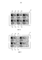
В дополнительном варианте осуществления первая маркерная область и/или вторая маркерная область содержат подобласти. Другими словами, маркерная область может состоять из множества меньших секций. Например, подобласти первой маркерной области и/или второй маркерной области расположены в шахматном порядке. Это гарантирует, что первые маркерные области и вторые маркерные области не разнесены слишком далеко друг от друга, при этом общая маркерная область по-прежнему покрывает требуемую область кожи.In a further embodiment, the first marker region and / or the second marker region contain subregions. In other words, the marker region may consist of a plurality of smaller sections. For example, the subregions of the first marker region and / or the second marker region are staggered. This ensures that the first marker regions and the second marker regions are not too far apart, while the common marker region still covers the desired skin area.
Согласно еще одному аспекту системы по настоящему изобретению маркер дополнительно содержит стимулятор для усиления перфузии крови в ткани субъекта, соприкасающейся с маркером. Как пояснялось выше, фотоплетизмография основана на изменении объема кровеносных сосудов в ткани. Следовательно, для увеличения мощности сигнала желательно обеспечить достаточный кровоток в сосудах под маркером, когда маркер нанесен на субъект, основные физиологические показатели которого требуется определить.According to another aspect of the system of the present invention, the marker further comprises a stimulant for enhancing blood perfusion in the tissue of the subject in contact with the marker. As explained above, photoplethysmography is based on changes in the volume of blood vessels in the tissue. Therefore, to increase the signal power, it is desirable to ensure sufficient blood flow in the vessels under the marker, when the marker is applied to the subject, the main physiological parameters of which are required to be determined.
КРАТКОЕ ОПИСАНИЕ ЧЕРТЕЖЕЙBRIEF DESCRIPTION OF THE DRAWINGS
Эти и другие аспекты изобретения станут понятны из вариантов осуществления, описанных ниже. На следующих чертежахThese and other aspects of the invention will become apparent from the embodiments described below. On the following drawings
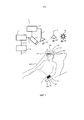
на Фиг. 1 показан пример осуществления системы для определения информации об основных физиологических показателях субъекта согласно настоящему изобретению;in FIG. 1 shows an example implementation of a system for determining information about the main physiological parameters of a subject according to the present invention;
на Фиг. 2 показано определение информации об основных физиологических показателях с помощью системы согласно настоящему изобретению;in FIG. 2 shows the definition of basic physiological information using the system according to the present invention;
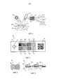
на Фиг. 3 показан первый пример маркера;in FIG. 3 shows a first marker example;
на Фиг. 4 показан второй пример маркера;in FIG. 4 shows a second marker example;
на Фиг. 5 показан третий пример маркера;in FIG. 5 shows a third marker example;
на Фиг. 6 показан пример маркера, имеющего подобласти;in FIG. 6 shows an example of a marker having sub-regions;
на Фиг. 7 показан альтернативный пример маркера, имеющего подобласти.in FIG. 7 shows an alternative example of a marker having subregions.
ПОДРОБНОЕ ОПИСАНИЕ ИЗОБРЕТЕНИЯDETAILED DESCRIPTION OF THE INVENTION
На Фиг. 1 показан пример осуществления системы 1 для определения информации 7 об основных физиологических показателях субъекта 100 согласно настоящему изобретению. Система 1 содержит маркер 10 для наложения на кожу субъекта 100, блок 2 обнаружения, а также блок 6 анализа в качестве основных составляющих. В этом примере система для определения информации об основных физиологических показателях субъекта используется в больничных условиях, где субъект 100 лежит в кровати 103.FIG. 1 shows an example implementation of
Маркер 10 дополнительно содержит первую маркерную область 11, выполненную с возможностью пропускания света на первой длине волны, а также вторую маркерную область 12, выполненную с возможностью пропускания света на второй длине волны. Блок 2 обнаружения выполнен с возможностью детектирования излучения, принятого от первой маркерной области 11, а также от второй маркерной области 12 маркера 10. В этом примере блок 2 обнаружения соединен с дополнительным блоком 4 обработки изображений. Блок 2 обнаружения предоставляет данные 3 об излучении, представляющие обнаруженное излучение, в блок 4 обработки изображений в виде потока видеоданных. Блок 4 обработки изображений идентифицирует первую маркерную область 11 и вторую маркерную область 12 в данных 3 об излучении. Блок 4 обработки изображений, в свою очередь, соединен с блоком 6 анализа. Блок 4 обработки изображений предоставляет предварительно обработанные данные 5 об излучении в блок 6 анализа. Предварительно обработанные данные 5 об излучении в этом примере содержат информацию о том, какая область изображений видеопотока данных 3 об излучении отображает первую маркерную область 11 и вторую маркерную область 12. Блок 6 анализа, в свою очередь, определяет информацию 7 об основных физиологических показателях субъекта из переменной во времени интенсивности в первой маркерной области 11 и во второй маркерной области 12. В этом примере информация об основных физиологических показателях содержит частоту сердечных сокращений и насыщение крови кислородом.The
Блок 4 обработки изображений для распознавания первой маркерной области 11 и второй маркерной области также может входить в состав блока 6 анализа. В качестве альтернативы данные 3 об излучении непосредственно предоставляются в блок 6 анализа. В этом случае как первая маркерная область 11, так и вторая маркерная область 12 могут определяться выбором вручную маркерных областей в изображениях потока видеоданных. В качестве альтернативы субъект 100 с маркером 10 должен располагаться в заданном положении в поле обзора блока 2 обнаружения, так чтобы первая маркерная область 11 и вторая маркерная область 12 находились в заданном положении. Однако автоматическая идентификация маркера 10 в данных 3 об излучении блоком 4 обработки изображений является предпочтительной.The image processing unit 4 for recognizing the
В показанном примере маркер 10 непосредственно нанесен на открытую кожу лба 101 субъекта 100. Альтернативный маркер 10', имеющий первую маркерную область 11' и вторую маркерную область 12', расположен на левом предплечье 102 субъекта 100. Размер и форма маркера 10, 10' могут выбираться в зависимости от анатомического местонахождения.In the example shown, the
Место действия освещается источником излучения, например солнечным светом 7a или источником 7b искусственного освещения. Источник 7a, 7b излучения напрямую или опосредованно испускает излучение 8a, 8b в направлении субъекта 100. Вдобавок или в качестве альтернативы система 1 также может содержать дополнительный источник 7c света системы, излучающий свет 8c в направлении субъекта 100. Использование источника 7c света системы в особенности полезно, если источники 7a, 7b света окружающей среды не обеспечивают достаточно света или если спектр источников 7a, 7b света окружающей среды не обладает достаточной мощностью на первой длине волны и на второй длине волны.The scene is illuminated by a radiation source, such as
Дополнительный блок 9 управления выполнен с возможностью регулировки чувствительности блока 2 обнаружения и/или регулировки мощности источника 7c света системы. Поскольку динамический диапазон детектора или датчика изображения, используемого в качестве блока 2 обнаружения, ограничен, затворы и электронные компенсации может потребоваться отрегулировать в соответствии с состоянием освещения в наблюдаемом изображении. Источник 7c света системы может являться частью контура управления, задающего оптимальный рабочий режим датчика изображения блока 2 обнаружения. Понятие «оптимальный» в данном контексте относится к выходному сигналу, не имеющему искажений, отсутствию насыщения отдельных детекторов или датчиков изображения, а также высокому показателю соотношения сигнал-шум, по меньшей мере, для площади чувствительной поверхности детектора, соответствующей первой и/или второй маркерной области.The
На Фиг. 2 проиллюстрировано определение информации об основных физиологических показателях субъекта с помощью системы 1 согласно настоящему изобретению. На Фиг. 2 показан источник 21 света, блок 22 обнаружения, а также маркер, имеющий первую маркерную область 23 и вторую маркерную область 24. Маркер нанесен на кожную ткань 104 субъекта. Ткань содержит кровеносные сосуды 105.FIG. 2 illustrates the determination of information about the main physiological parameters of a
В данном варианте осуществления источник 21 света испускает свет, по меньшей мере, на первой длине волны (помечено точечными линиями) и второй длине волны (помечено пунктирными линиями). Первая маркерная область 23 выполнена с возможностью пропускания света на первой длине волны, при этом упомянутая первая длина волны соответствует первой длине волны источника 21 света. Вторая маркерная область 24 выполнена с возможностью пропускания света на второй длине волны, при этом упомянутая вторая длина волны соответствует второй длине волны источника 21 света. На Фиг. 2 схематично изображены два световых луча A, B на первой длине волны и два световых луча C, D на второй длине волны. Поскольку первая маркерная область 23 выполнена с возможностью пропускания света на первой длине волны, луч A проходит сквозь маркер и проникает в кожу 104 субъекта 100. Часть светового излучения поглощается кожей 104, а часть светового излучения отражается или рассеивается в ткани и достигает блока 22 обнаружения. Характеристика поглощения и/или отражения изменяется во времени и представляет переменную во времени перфузию ткани 104 через ее кровеносные сосуды 105.In this embodiment, the
Блок 22 обнаружения содержит приемную оптику, например линзы приемника, а также матрицу 25 фотодетекторов или пикселей, образующих датчик изображения. Световое излучение, принятое от первой маркерной области, визуализируется на первой группе или матрице пикселей 26. Соответственно световое излучение, принятое от второй маркерной области 24, визуализируется на второй группе пикселей 27.The
Поскольку поглощение света в ткани 104 изменяется во времени, интенсивность света, падающего на датчик изображения блока 22 обнаружения, также изменяется во времени. Переменная во времени интенсивность в области пикселей 26 изображена кривой 28. Переменная во времени интенсивность света, падающего на группу пикселей 27, изображена кривой 29.Since the absorption of light in the
Поскольку первая маркерная область выполнена с возможностью пропускания света только на первой длине волны, свет на второй длине волны не проходит через эту маркерную область и не проникает в ткань, как показано световым лучом C. Тем не менее, часть светового излучения может рассеиваться в обратном направлении на поверхности маркера и достигать блока 22 обнаружения. Это световое излучение не модулировано пульсирующим изменением объема крови и вызывает погрешность. Модуляция интенсивности, изображенная кривой 28, таким образом, вызвана переменным во времени отражением в ткани 104 на первой длине волны.Since the first marker region is configured to transmit light only at the first wavelength, the light at the second wavelength does not pass through this marker region and does not penetrate the tissue, as indicated by the light beam C. However, part of the light emission can be scattered in the opposite direction on the surface of the marker and reach
Соответственно световой луч D на второй длине волны может проходить сквозь вторую маркерную область 24, в то время как световой луч B на первой длине волны не пропускается. Модуляция интенсивности, изображенная кривой 29, таким образом, вызвана переменным во времени отражением в ткани 104 на второй длине волны.Accordingly, the light beam D at the second wavelength can pass through the
Частота пульса субъекта может быть непосредственно определена из переменной во времени интенсивности по одной из кривых 28 или 29. Однако для определения насыщение крови кислородом с помощью фотоплетизмографии требуется, по меньшей мере, две длины волны, как поясняется ниже на примере.The subject's pulse rate can be directly determined from the time-variable intensity from one of the
Контактные пульсовые оксиметры обычно пропускают красный (R) или инфракрасный (IR) свет (или, точнее говоря, в некоторых случаях свет ближней инфракрасной области спектра) через сосудистую ткань исследуемого субъекта. Соответствующие части светового излучения (R/IR) могут пропускаться и детектироваться попеременно (в режиме быстрого переключения). Учитывая, что соответствующие спектральные участки по-разному поглощаются оксигенированным гемоглобином (Hb02) и восстановленным гемоглобином (Hb), в итоге можно рассчитать насыщение крови кислородом. В алгоритме оценки насыщения кислородом (S02) может использоваться соотношение сигналов, связанных с красной и инфракрасной частью спектра. Кроме того, алгоритм может учитывать непульсирующую составляющую сигнала. Обычно PPG сигнал содержит DC компоненту и относительно малую пульсирующую AC компоненту. Кроме того, оценка S02, как правило, предполагает использование эмпирически полученного калибровочного коэффициента, применяемого в отношении рассчитанных значений. Обычно калибровочный коэффициент (или калибровочная кривая) определяется после проведения референсных измерений, включающих инвазивные измерения насыщения крови кислородом. Калибровочный коэффициент необходим, поскольку PPG-устройство по существу определяет соотношение между частями (спектрального) сигнала, которое должно переводиться в значение насыщения крови кислородом, обычно включающее соотношение между Hb02 и Hb. Например, но не с целью ограничения настоящего раскрытия, оценка насыщения крови кислородом может основываться на следующем общем уравнении:Contact pulse oximeters typically transmit red (R) or infrared (IR) light (or, more precisely, in some cases, near-infrared light) through the vascular tissue of the subject under study. The corresponding parts of the light emission (R / IR) can be skipped and detected alternately (in the fast switching mode). Given that the corresponding spectral regions are absorbed differently by oxygenated hemoglobin (Hb0 2 ) and restored hemoglobin (Hb), in the end, it is possible to calculate the blood oxygen saturation. The algorithm for estimating oxygen saturation (S0 2 ) can use the ratio of signals associated with the red and infrared part of the spectrum. In addition, the algorithm can take into account the non-pulsing component of the signal. Typically, a PPG signal contains a DC component and a relatively small pulsating AC component. In addition, an estimate of S0 2 typically involves the use of an empirically derived calibration factor applied to the calculated values. Usually, the calibration factor (or calibration curve) is determined after carrying out reference measurements, including invasive measurements of blood oxygen saturation. The calibration factor is necessary because the PPG device essentially determines the ratio between the parts of the (spectral) signal, which should be translated into the value of blood oxygen saturation, usually including the ratio between Hb0 2 and Hb. For example, but not for the purpose of limiting the present disclosure, an estimate of blood oxygen saturation may be based on the following general equation:
SO2=Hb02/(Hb02+Hb), (1)SO 2 = Hb0 2 / (Hb0 2 + Hb), (1)
при этом PPG-устройства лишь опосредованно определяют Hb02 и Hb из спектральной характеристики, по меньшей мере, на двух длинах волн.however, PPG devices only indirectly determine HbO 2 and Hb from the spectral characteristics at least at two wavelengths.
Вообще измеренная кривая интенсивности 28, 29, используемая в качестве характеристического сигнала, рассматривается как содержащая постоянный (DC) участок и переменный (AC) участок, наложенный на DC участок. Применяя способы обработки сигналов, AC участок может быть выделен, а кроме того, могут быть введены поправки на помехи. Например, AC участок характеристического сигнала может содержать доминантную частоту, которая может быть весьма показательной в отношении сосудистой деятельности субъекта 100, в частности биения сердца. В то же время характеристический сигнал, в частности AC участок, может быть показательным в отношении других жизненно важных параметров. В этой связи определение насыщения артериальной крови кислородом – важная область применения. Как указано выше, по существу значения, представляющие насыщение крови кислородом, могут вычисляться с учетом характера изменения AC участка характеристического сигнала на его дискретных участках спектра. Другими словами, степень насыщения артериальной крови кислородом может отражаться в неодинаковом поглощении излучения на кровеносных сосудах. Кроме того, может использоваться тот факт, что различие в поглощении вследствие степени насыщения кислородом также может существенно варьироваться по различным спектральным участкам. Помимо этого, DC участок сигнала также может использоваться для определения насыщения крови кислородом. Обычно DC компонента представляет общее поглощение света тканью, венозной кровью, а также непульсирующей артериальной кровью. Наоборот, AC компонента может представлять поглощение пульсирующей артериальной кровью. Следовательно, определение насыщения артериальной крови кислородом (Sa02) можно выразить следующим образом:In general, the measured
SaO2=C(AC/DC)red/(AC/DC)infrared, (2) где C - калибровочный коэффициент. Коэффициент C может обозначать самые разные калибровочные коэффициенты, применимые к соотношению AC/DC, а значит, не должен восприниматься в строго алгебраическом смысле уравнения (2). Коэффициент C, например, может представлять величину, имеющую постоянное значение, набор констант или регулируемый калибровочный коэффициент. В качестве примера другая типовая модель получения Sa02 может быть выражена следующим образом: SaO 2 = C (AC / DC) red / (AC / DC) infrared, (2) where C is the calibration factor. Coefficient C may denote a variety of calibration coefficients applicable to the AC / DC ratio, and therefore, should not be perceived in the strictly algebraic sense of equation (2). The coefficient C, for example, may represent a value having a constant value, a set of constants or an adjustable calibration factor. As an example, another typical model for obtaining Sa0 2 can be expressed as follows:
SaO2=C1+C2(AC/DC)red/(AC/DC)infrared, (3) где C1 и C2 могут рассматриваться в качестве калибровочных коэффициентов линейной аппроксимации. В одном примере осуществления определение коэффициента калибровки сигнала может быть направлено на регулировку или согласование коэффициента C1. Кроме того, в качестве альтернативы получение Sa02 может также основываться на таблицах значений, внесенных в устройство 1 (или доступных ему). Таблицы значений (или базы данных) могут обеспечивать дискретное представление соотношения между распознанными PPG сигналами и требуемым калибровочным коэффициентом. В этом случае может также применяться настраиваемый калибровочный коэффициент для повышения точности определения жизненно важных показателей.SaO 2 = C 1 + C 2 (AC / DC) red / (AC / DC) infrared, (3) where C 1 and C 2 can be considered as linear approximation calibration coefficients. In one embodiment, the determination of the signal calibration factor may be directed to adjusting or adjusting the coefficient C 1 . In addition, alternatively, obtaining Sa0 2 can also be based on tables of values entered into device 1 (or those available to it). Value tables (or databases) can provide a discrete representation of the relationship between the recognized PPG signals and the required calibration factor. In this case, a custom calibration factor can also be used to improve the accuracy of determining vital signs.
Следует понимать, что уравнения (2) и (3) представлены главным образом в иллюстративных целях. Их не следует рассматривать как ограничивающие объем настоящего раскрытия. На практике специалист сможет предложить дополнительные соответствующие модели для определения Sa02. Альтернативные сочетания длин волн, например в зеленой и красной области спектра, могут использоваться в зависимости от распознаваемого вещества. Хотя измерение Sa02 было описано подробно, его следует понимать как пример общей концепции измерения концентрации вещества в крови и/или ткани.It should be understood that equations (2) and (3) are presented mainly for illustrative purposes. They should not be construed as limiting the scope of the present disclosure. In practice, the specialist will be able to propose additional relevant models for determining Sa0 2 . Alternative combinations of wavelengths, for example in the green and red regions of the spectrum, can be used depending on the substance to be recognized. Although the measurement of Sa0 2 has been described in detail, it should be understood as an example of a general concept of measuring the concentration of a substance in the blood and / or tissue.
На Фиг. 3 более подробно показан вариант осуществления маркера для использования в системе 1 с целью определения информации об основных физиологических показателях субъекта согласно настоящему изобретению. Маркер 30 имеет первый графический паттерн 32, второй графический паттерн 33, референсные области 34a, 35a, 36a, 37A, маркерные области 34b, 35b, 36b, выполненные с возможностью пропускания света на трех различных длинах волн, а также прозрачную маркерную область 37b.FIG. 3 shows in more detail an embodiment of a marker for use in
Несущий элемент 31 является носителем маркера 30 с его элементами, а также обеспечивает механическую устойчивость. В данном варианте осуществления несущий элемент 31 представляет собой пластырь или лейкопластырь, который может непосредственно крепиться к коже субъекта 100 с помощью адгезива. Несущий элемент выполнен из светонепроницаемого резиноподобного материала, не пропускающего свет. В этой связи, несущий элемент имеет отверстия или окна в местах расположения маркераных областей 34b, 35b, 36b, 37b.The
В каждом из окон 34b, 35b, 36b расположена пластина оптического фильтра, при этом пластина 34b фильтра выполнена с возможностью пропускания света на первой длине волны, пластина 35b фильтра выполнена с возможностью пропускания света на второй длине волны, а пластина 36b фильтра выполнена с возможностью пропускания света на третьей длине волны. Маркерная область 37b не имеет частотно-избирательного фильтра и является прозрачной, так что кожа под областью 37b визуально доступна блоку обнаружения в качестве не закрытой фильтром референсной области кожи.An optical filter plate is arranged in each of the
Референсные области 34a, 35a, 36a являются референсными областями для конкретных длин волн. Предпочтительно цвет референсной области соответствует длине волны пропускания соседнего фильтра. Например, маркерная область 34b выполнена с возможностью пропускания красного света, при этом референсная область 34a имеет красный цвет, так что оно может служить в качестве указателя, в частности, того, сколько красного света имеется в излучении, падающем на маркер.
Графический паттерн 32 служит в качестве индикатора выставления. Геометрическая конструкция позволяет блоку 4 обработки изображений определить положение и/или ориентацию маркера 30. Маркер 30, помимо этого, имеет машиночитаемый графический паттерн 33 в виде QR-кода. Данный код содержит информацию о субъекте, так что полученная информация об основных физиологических показателях может приписываться к субъекту, например, заноситься в электронную медицинскую карту (EHR). Код также может содержать информацию об участке, на котором маркер крепится к телу субъекта, так что на одном субъекте могут одновременно проводиться различные измерения, индивидуальные для места измерения (например, лоб и рука).
Хотя на Фиг. 3 представлено множество признаков, не все они являются обязательными. На Фиг. 4 показана основная конфигурация, в которой имеются две маркерные области. В этом примере маркер содержит первый краситель, непосредственно наносимый на кожу субъекта в первой маркерной области, а также второй краситель, непосредственно наносимый на кожу субъекта во второй маркерной области. Краситель может представлять собой, например, эластомер, отштампованный, вычерченный, нанесенный напылением или отпечатанный на коже. Краситель первой маркерной области выполнен с возможностью пропускания света на первой длине волны, в то время как краситель во второй маркерной области выполнен с возможностью пропускания света на второй длине волны. Соответственно может применяться дополнительная референсная область.Although FIG. 3 presents many features, not all of them are required. FIG. 4 shows the basic configuration in which there are two marker regions. In this example, the marker contains the first dye applied directly to the skin of the subject in the first marker region, as well as the second dye applied directly to the skin of the subject in the second marker region. The dye may be, for example, an elastomer, stamped, drawn, sprayed or printed on the skin. The dye of the first marker region is adapted to transmitting light at the first wavelength, while the dye in the second marker region is adapted to transmitting light at the second wavelength. Accordingly, an additional reference area may be applied.
На Фиг. 5 показан вид сбоку маркера, схожего с тем, что представлен на Фиг. 3. Он закреплен на коже 104 субъекта. Несущий элемент 51 придает механическую устойчивость маркеру 50. На стороне несущего элемента 51, обращенной к коже 104 субъекта, несущий элемент 51 содержит адгезив 52 для крепления несущего элемента к коже 104 субъекта. Адгезив 52 дополнительно содержит стимулятор для увеличения перфузии крови в ткани 104 субъекта, соприкасающейся с несущим элементом 51, на котором расположен маркер 50.FIG. 5 is a side view of a marker similar to that shown in FIG. 3. It is fixed on the skin of the 104 subject. The
На противоположной стороне несущего элемента 51 маркер 50 имеет референсные области 54a, 55a, а также первую маркерную область 54b, выполненную с возможностью пропускания света на первой длине волны, и вторую маркерную область 55b, выполненную с возможностью пропускания света на второй длине волны. Это достигается благодаря пластинам 56, 57 оптических фильтров, расположенным на месте первой и второй маркерных областей и заламинированным в несущий элемент 51. В качестве опции адгезив не наносится в маркерных областях 54b, 55b, чтобы не оказывать влияния на характеристику пропускания маркераных областей.On the opposite side of the
На Фиг. 6 и 7 показаны различные паттерны оптических окон вместе с первой и второй маркерными областями, а также референсными областями. В этом примере первая и вторая маркерные области разделены на подобласти. Паттерны референсных областей и оптические окна, содержащие первую и вторую маркерные области, могут выбираться в соответствии с потребностями в конкретном измерении.FIG. 6 and 7 show various patterns of optical windows along with the first and second marker regions, as well as reference regions. In this example, the first and second marker regions are divided into subregions. Reference area patterns and optical windows containing the first and second marker regions can be selected according to the needs in a particular dimension.
Для проведения некоторых измерений важно получить сигналы для каждой длины волны из близкорасположенных областей ткани. В этом случае предпочтительно иметь несколько меньших по размеру оптических окон, например расположенных в шахматном порядке. На Фиг. 6 показан маркер 60 с шахматной схемой расположения для двух длин волн с чередованием референсных областей 61a и первых маркерных областей 61b для первой длины волны, а также референсных областей 62a и вторых маркерных областей 62b для второй длина волны. Например, для измерения насыщения крови кислородом красная область спектра используется в качестве первой длины волны, а инфракрасная область спектра используется в качестве второй длины волны.For some measurements, it is important to obtain signals for each wavelength from closely located areas of tissue. In this case, it is preferable to have several smaller optical windows, for example, staggered. FIG. 6 shows a staggered
На Фиг. 7 показан альтернативный вариант осуществления маркера 70, при этом распределение референсных областей 71a, 72a и оптических окон для первых и вторых маркерных областей 71b, 72b оптимизируется в зависимости от ожидаемой мощности сигнала. Например, сигнал на первой требуемой длине волны, например зеленой области спектра, мощнее сигнала на второй требуемой длине волны, например красной области спектра. Таким образом, общая вторая маркерная область 72b увеличивается относительно общей первой маркерной области 71b, чтобы достичь той же мощности сигнала на обеих длинах волн.FIG. 7 shows an alternative embodiment of the
В качестве примера настоящее изобретение может применяться в области здравоохранения, например для ненавязчивого удаленного мониторинга пациента, общего наблюдения, контроля состояния безопасности и в так называемых средах, определяемых стилем жизни, например в оборудовании для занятий фитнесом, и т.п. Сферы применения могут включать мониторинг насыщения кислородом (пульсовую оксиметрию), частоты сердечных сокращений, кровяного давления, функционального состояния сердца, изменения перфузии крови, оценку автономных функций, а также обнаружение заболеваний периферических кровеносных сосудов.As an example, the present invention can be applied in the field of health care, for example, for unobtrusive remote patient monitoring, general observation, security monitoring and in so-called lifestyle-defined environments, for example, in fitness equipment, etc. Applications may include monitoring oxygen saturation (pulse oximetry), heart rate, blood pressure, cardiac function, changes in blood perfusion, assessment of autonomic functions, and the detection of peripheral blood vessel disease.
Хотя изобретение проиллюстрировано на чертежах и подробно представлено в вышеприведенном описании, эти иллюстрации и описание следует рассматривать как приведенные в качестве примера, но не ограничивающие; изобретение не ограничено раскрытыми вариантами осуществления. Специалисты в данной области техники смогут предложить и реализовать другие модификации раскрытых вариантов осуществления, применяя на практике заявленное изобретение, изучив чертежи, описание и прилагаемую формулу изобретения.Although the invention is illustrated in the drawings and is described in detail in the above description, these illustrations and the description should be considered as an example, but not limiting; The invention is not limited to the disclosed embodiments. Specialists in this field of technology will be able to offer and implement other modifications of the disclosed embodiments, applying in practice the claimed invention, having examined the drawings, the description and the attached claims.
В формуле изобретения термин "содержащий" не исключает наличия других элементов или этапов, а неопределенный артикль "a" или "an" не исключает множества. Единственный элемент или другой блок может выполнять функции нескольких объектов, перечисленных в формуле изобретения. Тот факт, что определенные меры упоминаются во взаимно отличных зависимых пунктах формулы изобретения, не означает, что сочетание этих мер не может быть использовано с выгодой.In the claims, the term "comprising" does not exclude the presence of other elements or steps, and the indefinite article "a" or "an" does not exclude a plurality. A single element or other unit may fulfill the functions of several items listed in the claims. The fact that certain measures are mentioned in the mutually distinct dependent claims does not mean that a combination of these measures cannot be used to advantage.
Компьютерная программа может храниться/быть распределена на подходящем энергонезависимом носителе, таком как оптический носитель информации или твердотельный носитель, поставляемом совместно с другим аппаратным обеспечением или в виде его части, однако может также быть распределена в других формах, например через Интернет или другие проводные или беспроводные телекоммуникационные системы.The computer program may be stored / distributed on a suitable non-volatile medium, such as optical media or solid-state media, supplied with or in part to other hardware, but may also be distributed in other forms, such as via the Internet or other wired or wireless media. telecommunication systems.
Ни одну из ссылочных позиций не следует рассматривать, как ограничивающую объем изобретения.None of the reference positions should be construed as limiting the scope of the invention.
Claims (22)
Applications Claiming Priority (5)
| Application Number | Priority Date | Filing Date | Title |
|---|---|---|---|
| US201361760683P | 2013-02-05 | 2013-02-05 | |
| US61/760,683 | 2013-02-05 | ||
| EP13154017.1A EP2762066A1 (en) | 2013-02-05 | 2013-02-05 | System and method for determining vital sign information of a subject |
| EP13154017.1 | 2013-02-05 | ||
| PCT/EP2014/052143 WO2014122126A1 (en) | 2013-02-05 | 2014-02-04 | System and method for determining vital sign information of a subject |
Publications (2)
| Publication Number | Publication Date |
|---|---|
| RU2015137775A RU2015137775A (en) | 2017-03-13 |
| RU2688445C2 true RU2688445C2 (en) | 2019-05-21 |
Family
ID=47630213
Family Applications (1)
| Application Number | Title | Priority Date | Filing Date |
|---|---|---|---|
| RU2015137775A RU2688445C2 (en) | 2013-02-05 | 2014-02-04 | System and method for determining information on basic physiological indicators of a subject |
Country Status (10)
| Country | Link |
|---|---|
| US (2) | US10660524B2 (en) |
| EP (3) | EP2762066A1 (en) |
| JP (2) | JP6388604B2 (en) |
| CN (2) | CN104968259B (en) |
| BR (1) | BR112015018351A2 (en) |
| CA (1) | CA2899988A1 (en) |
| MX (1) | MX2015009946A (en) |
| RU (1) | RU2688445C2 (en) |
| WO (2) | WO2014122126A1 (en) |
| ZA (1) | ZA201506510B (en) |
Families Citing this family (30)
| Publication number | Priority date | Publication date | Assignee | Title |
|---|---|---|---|---|
| MX2014015052A (en) | 2012-06-12 | 2015-03-03 | Koninkl Philips Nv | System for camera-based vital sign measurement. |
| EP3062701B1 (en) | 2013-11-01 | 2021-01-13 | Koninklijke Philips N.V. | System and method for determining vital sign information of a subject |
| CN105266759A (en) * | 2014-05-26 | 2016-01-27 | 义明科技股份有限公司 | Physiological signal detection device |
| WO2016057633A1 (en) | 2014-10-08 | 2016-04-14 | Revealix, Inc. | Automated systems and methods for skin assessment and early detection of a latent pathogenic bio-signal anomaly |
| US10242278B2 (en) | 2014-12-01 | 2019-03-26 | Koninklijke Philips N.V. | Device and method for skin detection |
| WO2016111696A1 (en) * | 2015-01-09 | 2016-07-14 | Lifeq Global Limited | A ppg-based physiological sensing system with a spatio-temporal sampling approach towards identifying and removing motion artifacts from optical signals |
| CN106236060B (en) * | 2015-06-04 | 2021-04-09 | 松下知识产权经营株式会社 | Biological information detection device |
| US11154203B2 (en) | 2015-06-14 | 2021-10-26 | Facense Ltd. | Detecting fever from images and temperatures |
| US11103139B2 (en) | 2015-06-14 | 2021-08-31 | Facense Ltd. | Detecting fever from video images and a baseline |
| JP6625219B2 (en) * | 2015-12-21 | 2019-12-25 | コーニンクレッカ フィリップス エヌ ヴェKoninklijke Philips N.V. | Device, method and computer program product for continuous monitoring of vital signs |
| US10694988B2 (en) * | 2016-02-17 | 2020-06-30 | Nuralogix Corporation | System and method for detecting physiological state |
| US10398324B2 (en) | 2016-03-03 | 2019-09-03 | Board Of Trustees Of Michigan State University | Method and apparatus for cuff-less blood pressure measurement in a mobile device |
| WO2017152098A1 (en) * | 2016-03-03 | 2017-09-08 | Board Of Trustees Of Michigan State University | Method and apparatus for cuff-less blood pressure measurement |
| JP2017176267A (en) * | 2016-03-28 | 2017-10-05 | 富士ゼロックス株式会社 | Biological information measurement device and light-emitting device |
| US10335045B2 (en) | 2016-06-24 | 2019-07-02 | Universita Degli Studi Di Trento | Self-adaptive matrix completion for heart rate estimation from face videos under realistic conditions |
| JP7116042B2 (en) * | 2016-08-09 | 2022-08-09 | コーニンクレッカ フィリップス エヌ ヴェ | Devices, systems and methods for monitoring peripheral arterial perfusion in a subject |
| EP3510379B1 (en) * | 2016-09-08 | 2023-09-27 | PreSens - Precision Sensing GmbH | Method for calibrated luminescence measurement and system therefor |
| CN108125673B (en) * | 2016-12-01 | 2023-03-14 | 松下知识产权经营株式会社 | Biological information detection device |
| CA3076478C (en) * | 2017-09-21 | 2021-11-16 | Vital Biosciences, Inc. | Imaging biological tissue or other subjects |
| CN111246818B (en) * | 2017-09-22 | 2024-02-23 | 直观外科手术操作公司 | Enhancing visible differences between different tissues in computer-assisted teleoperated surgery |
| CN111386068B (en) | 2017-10-24 | 2023-05-30 | 纽洛斯公司 | Pressure measurement system and method based on camera |
| US10646145B2 (en) * | 2018-02-09 | 2020-05-12 | General Electric Company | Reflective SpO2 measurement system and method |
| CN108852307B (en) * | 2018-05-24 | 2020-11-24 | 重庆理工大学 | Non-contact non-invasive arteriosclerosis detection device |
| JP2021530341A (en) | 2018-07-16 | 2021-11-11 | ビービーアイ、メディカル、イノベーションズ、リミテッド、ライアビリティー、カンパニーBbi Medical Innovations, Llc | Measurement of perfusion and oxygenation |
| EP3613337A1 (en) * | 2018-08-22 | 2020-02-26 | Nokia Technologies Oy | An apparatus, method and computer program for determining a biometric parameter |
| US11681886B2 (en) * | 2018-09-06 | 2023-06-20 | John P. Peeters | Genomic and environmental blockchain sensors |
| US11779222B2 (en) * | 2019-07-10 | 2023-10-10 | Compal Electronics, Inc. | Method of and imaging system for clinical sign detection |
| TWI772689B (en) * | 2019-10-09 | 2022-08-01 | 鉅怡智慧股份有限公司 | Non-contact physiological signal measuring device |
| CN112617746B (en) * | 2019-10-09 | 2024-04-09 | 钜怡智慧股份有限公司 | Non-contact physiological signal detection device |
| US12076141B2 (en) | 2021-02-26 | 2024-09-03 | Covidien Lp | System and method for digitally calibrating a medical sensor |
Citations (8)
| Publication number | Priority date | Publication date | Assignee | Title |
|---|---|---|---|---|
| US5267563A (en) * | 1991-06-28 | 1993-12-07 | Nellcor Incorporated | Oximeter sensor with perfusion enhancing |
| US20050106713A1 (en) * | 2003-09-03 | 2005-05-19 | Phan Brigitte C. | Personal diagnostic devices and related methods |
| US20070142715A1 (en) * | 2005-12-20 | 2007-06-21 | Triage Wireless, Inc. | Chest strap for measuring vital signs |
| US20100112680A1 (en) * | 2006-07-11 | 2010-05-06 | Paul Nigel Brockwell | Indicator system for determining analyte concentration |
| RU2420232C2 (en) * | 2005-10-27 | 2011-06-10 | СМИТС МЕДИКАЛ ПиЭм, ИНК. | Disposable pulse oxymeter |
| WO2011097139A2 (en) * | 2010-02-02 | 2011-08-11 | Recovery Science And Technology, Llc. | Recovery determination methods and recovery determination apparatuses |
| WO2011112559A2 (en) * | 2010-03-08 | 2011-09-15 | Bruce Adams | System, method and article for normalization and enhancement of tissue images |
| US20110290005A1 (en) * | 2008-07-24 | 2011-12-01 | Hart Douglas P | Dynamic three-dimensional imaging of ear canals |
Family Cites Families (37)
| Publication number | Priority date | Publication date | Assignee | Title |
|---|---|---|---|---|
| US5441048A (en) * | 1988-09-08 | 1995-08-15 | Sudor Partners | Method and apparatus for determination of chemical species in perspiration |
| GB9011887D0 (en) * | 1990-05-26 | 1990-07-18 | Le Fit Ltd | Pulse responsive device |
| US5544649A (en) | 1992-03-25 | 1996-08-13 | Cardiomedix, Inc. | Ambulatory patient health monitoring techniques utilizing interactive visual communication |
| JPH06285048A (en) | 1993-03-19 | 1994-10-11 | Nellcor Inc | Oxygen analyzer with perfusion enhancing means |
| JP3547968B2 (en) * | 1998-01-19 | 2004-07-28 | 株式会社日本自動車部品総合研究所 | Pulse waveform detector |
| US6352517B1 (en) | 1998-06-02 | 2002-03-05 | Stephen Thomas Flock | Optical monitor of anatomical movement and uses thereof |
| US6980679B2 (en) * | 1998-10-23 | 2005-12-27 | Varian Medical System Technologies, Inc. | Method and system for monitoring breathing activity of a subject |
| US20050027182A1 (en) | 2001-12-27 | 2005-02-03 | Uzair Siddiqui | System for monitoring physiological characteristics |
| JP2004187980A (en) | 2002-12-12 | 2004-07-08 | Fuji Photo Film Co Ltd | Medical image processor and medical image processing method |
| CN101366632A (en) * | 2004-08-03 | 2009-02-18 | 武汉一海数字工程有限公司 | Mammary tissue blood oxygen function imaging system |
| DE102005036410A1 (en) | 2005-07-29 | 2007-02-01 | Biocam Gmbh | Method for determining the oxygen partial pressure distribution in at least one tissue surface section, in particular skin tissue surface section |
| US20100056887A1 (en) * | 2006-11-27 | 2010-03-04 | Pioneer Corporation | Emission sensor device and bioinformation detecting method |
| US7434724B2 (en) * | 2006-12-22 | 2008-10-14 | Welch Allyn, Inc. | Dynamic barcode for displaying medical data |
| JP2008167853A (en) | 2007-01-10 | 2008-07-24 | Fujifilm Corp | Test sheet, object diagnostic apparatus and method, and program |
| JP5061353B2 (en) | 2007-06-19 | 2012-10-31 | 富士フイルム株式会社 | Inspection sheet |
| US20080317628A1 (en) * | 2007-06-19 | 2008-12-25 | Fujifilm Corporation | Check sheet |
| WO2009104394A1 (en) * | 2008-02-18 | 2009-08-27 | パナソニック株式会社 | Compound eye camera module |
| US20090226071A1 (en) * | 2008-03-06 | 2009-09-10 | Motorola, Inc. | Method and Apparatus to Facilitate Using Visible Light Images to Determine a Heart Rate |
| US10729357B2 (en) | 2010-04-22 | 2020-08-04 | Leaf Healthcare, Inc. | Systems and methods for generating and/or adjusting a repositioning schedule for a person |
| US20100268094A1 (en) * | 2009-04-15 | 2010-10-21 | Oceanit Laboratories Inc. | Consumer electronic camera photoplethysmograph |
| EP2454696A1 (en) | 2009-07-15 | 2012-05-23 | Koninklijke Philips Electronics N.V. | Method for automatic setting time varying parameter alert and alarm limits |
| US8670812B2 (en) * | 2009-07-23 | 2014-03-11 | Covidien Lp | Physiological sensor having a waist |
| FR2949658B1 (en) * | 2009-09-07 | 2012-07-27 | Salim Mimouni | OPTICAL PLETHYSMOGRAPHIC SIGNAL CAPTURE DEVICE USING MATRIX IMAGER |
| CN102647941B (en) * | 2009-10-06 | 2015-11-25 | 皇家飞利浦电子股份有限公司 | For performing the method and system of long-range photoplethaysmography |
| CN102576458B (en) * | 2009-10-06 | 2015-08-19 | 皇家飞利浦电子股份有限公司 | Carry out analyzing to characterize the method and system of at least one cyclical component of this first signal for obtaining the first signal |
| JP2011147469A (en) * | 2010-01-19 | 2011-08-04 | Rohm Co Ltd | Biological information acquisition device |
| JP5446915B2 (en) * | 2010-01-21 | 2014-03-19 | セイコーエプソン株式会社 | Biological information detector and biological information measuring device |
| US8761853B2 (en) * | 2011-01-20 | 2014-06-24 | Nitto Denko Corporation | Devices and methods for non-invasive optical physiological measurements |
| CA2825331A1 (en) * | 2011-01-21 | 2012-07-26 | Worcester Polytechnic Institute | Physiological parameter monitoring with a mobile communication device |
| US8718748B2 (en) | 2011-03-29 | 2014-05-06 | Kaliber Imaging Inc. | System and methods for monitoring and assessing mobility |
| DE102011017064A1 (en) * | 2011-04-14 | 2012-10-18 | Ingo Flore | Diagnostic measuring device with integrated spectrometer |
| US10178957B2 (en) * | 2011-04-21 | 2019-01-15 | Koninklijke Philips N.V. | Device and method for vital sign measurement of a person |
| US10521900B2 (en) | 2011-09-02 | 2019-12-31 | Koninklijke Philips N.V. | Camera for generating a biometrical signal of a living being |
| US20130267854A1 (en) * | 2012-04-09 | 2013-10-10 | Jami Johnson | Optical Monitoring and Computing Devices and Methods of Use |
| US20130303921A1 (en) * | 2012-05-11 | 2013-11-14 | Hong Kong Applied Science and Technology Research Institute Company Limited | System and Method for Measurement of Physiological Data with Light Modulation |
| MX2014015052A (en) * | 2012-06-12 | 2015-03-03 | Koninkl Philips Nv | System for camera-based vital sign measurement. |
| JP6285048B2 (en) | 2014-11-28 | 2018-02-28 | 堺ディスプレイプロダクト株式会社 | Backlight device and liquid crystal display device |
-
2013
- 2013-02-05 EP EP13154017.1A patent/EP2762066A1/en not_active Withdrawn
-
2014
- 2014-01-28 US US14/165,642 patent/US10660524B2/en not_active Expired - Fee Related
- 2014-02-04 CA CA2899988A patent/CA2899988A1/en not_active Abandoned
- 2014-02-04 US US14/764,588 patent/US9980650B2/en not_active Expired - Fee Related
- 2014-02-04 RU RU2015137775A patent/RU2688445C2/en not_active IP Right Cessation
- 2014-02-04 JP JP2015555747A patent/JP6388604B2/en not_active Expired - Fee Related
- 2014-02-04 BR BR112015018351A patent/BR112015018351A2/en not_active IP Right Cessation
- 2014-02-04 WO PCT/EP2014/052143 patent/WO2014122126A1/en active Application Filing
- 2014-02-04 CN CN201480007187.6A patent/CN104968259B/en not_active Expired - Fee Related
- 2014-02-04 EP EP14704928.2A patent/EP2953530A1/en not_active Withdrawn
- 2014-02-04 CN CN201480007177.2A patent/CN104981200B/en not_active Expired - Fee Related
- 2014-02-04 MX MX2015009946A patent/MX2015009946A/en unknown
- 2014-02-04 EP EP14702292.5A patent/EP2953529A1/en not_active Withdrawn
- 2014-02-04 JP JP2015555844A patent/JP6525890B2/en not_active Expired - Fee Related
- 2014-02-04 WO PCT/IB2014/058781 patent/WO2014122577A1/en active Application Filing
-
2015
- 2015-09-04 ZA ZA2015/06510A patent/ZA201506510B/en unknown
Patent Citations (8)
| Publication number | Priority date | Publication date | Assignee | Title |
|---|---|---|---|---|
| US5267563A (en) * | 1991-06-28 | 1993-12-07 | Nellcor Incorporated | Oximeter sensor with perfusion enhancing |
| US20050106713A1 (en) * | 2003-09-03 | 2005-05-19 | Phan Brigitte C. | Personal diagnostic devices and related methods |
| RU2420232C2 (en) * | 2005-10-27 | 2011-06-10 | СМИТС МЕДИКАЛ ПиЭм, ИНК. | Disposable pulse oxymeter |
| US20070142715A1 (en) * | 2005-12-20 | 2007-06-21 | Triage Wireless, Inc. | Chest strap for measuring vital signs |
| US20100112680A1 (en) * | 2006-07-11 | 2010-05-06 | Paul Nigel Brockwell | Indicator system for determining analyte concentration |
| US20110290005A1 (en) * | 2008-07-24 | 2011-12-01 | Hart Douglas P | Dynamic three-dimensional imaging of ear canals |
| WO2011097139A2 (en) * | 2010-02-02 | 2011-08-11 | Recovery Science And Technology, Llc. | Recovery determination methods and recovery determination apparatuses |
| WO2011112559A2 (en) * | 2010-03-08 | 2011-09-15 | Bruce Adams | System, method and article for normalization and enhancement of tissue images |
Also Published As
| Publication number | Publication date |
|---|---|
| CN104981200A (en) | 2015-10-14 |
| WO2014122126A1 (en) | 2014-08-14 |
| CA2899988A1 (en) | 2014-08-14 |
| JP2016508777A (en) | 2016-03-24 |
| US9980650B2 (en) | 2018-05-29 |
| MX2015009946A (en) | 2015-09-29 |
| US10660524B2 (en) | 2020-05-26 |
| EP2762066A1 (en) | 2014-08-06 |
| EP2953530A1 (en) | 2015-12-16 |
| US20140221847A1 (en) | 2014-08-07 |
| CN104968259A (en) | 2015-10-07 |
| CN104981200B (en) | 2018-10-16 |
| BR112015018351A2 (en) | 2017-07-18 |
| ZA201506510B (en) | 2017-08-30 |
| RU2015137775A (en) | 2017-03-13 |
| JP6525890B2 (en) | 2019-06-05 |
| JP2016511659A (en) | 2016-04-21 |
| CN104968259B (en) | 2018-07-13 |
| US20150366455A1 (en) | 2015-12-24 |
| WO2014122577A1 (en) | 2014-08-14 |
| EP2953529A1 (en) | 2015-12-16 |
| JP6388604B2 (en) | 2018-09-12 |
Similar Documents
| Publication | Publication Date | Title |
|---|---|---|
| RU2688445C2 (en) | System and method for determining information on basic physiological indicators of a subject | |
| US11147456B2 (en) | Marker with light emitting area for use in determining vital sign information | |
| RU2677765C2 (en) | System for screening of state of oxygenation of subject | |
| US9999355B2 (en) | Device, system and method for determining vital signs of a subject based on reflected and transmitted light | |
| CN105979861B (en) | Device, system and method for determining vital signs of a subject based on reflected and transmitted light | |
| EP3806740B1 (en) | System and method for determining at least one vital sign of a subject | |
| US11712185B2 (en) | Device, system and method for extracting physiological information indicative of at least one vital sign of a subject | |
| US20220265150A1 (en) | Device, system and method for determining physiological information | |
| US20210236015A1 (en) | System and method for determining at least one vital sign of a subject |
Legal Events
| Date | Code | Title | Description |
|---|---|---|---|
| MM4A | The patent is invalid due to non-payment of fees |
Effective date: 20200205 |