RU2685544C2 - Rotor for electric machine - Google Patents
Rotor for electric machine Download PDFInfo
- Publication number
- RU2685544C2 RU2685544C2 RU2017134487A RU2017134487A RU2685544C2 RU 2685544 C2 RU2685544 C2 RU 2685544C2 RU 2017134487 A RU2017134487 A RU 2017134487A RU 2017134487 A RU2017134487 A RU 2017134487A RU 2685544 C2 RU2685544 C2 RU 2685544C2
- Authority
- RU
- Russia
- Prior art keywords
- rotor according
- frame
- rotor
- jumpers
- outer frame
- Prior art date
Links
- 230000005294 ferromagnetic effect Effects 0.000 claims abstract description 20
- 239000003302 ferromagnetic material Substances 0.000 claims abstract description 16
- 239000004020 conductor Substances 0.000 claims abstract description 7
- 230000000295 complement effect Effects 0.000 claims abstract description 4
- 230000005291 magnetic effect Effects 0.000 claims description 17
- 230000004907 flux Effects 0.000 claims description 16
- 238000000034 method Methods 0.000 claims description 15
- 230000008569 process Effects 0.000 claims description 8
- 238000005520 cutting process Methods 0.000 claims description 6
- 238000003698 laser cutting Methods 0.000 claims description 6
- 238000003801 milling Methods 0.000 claims description 6
- XLYOFNOQVPJJNP-UHFFFAOYSA-N water Substances O XLYOFNOQVPJJNP-UHFFFAOYSA-N 0.000 claims description 6
- RYGMFSIKBFXOCR-UHFFFAOYSA-N Copper Chemical compound [Cu] RYGMFSIKBFXOCR-UHFFFAOYSA-N 0.000 claims description 4
- 229910000831 Steel Inorganic materials 0.000 claims description 4
- 229910052782 aluminium Inorganic materials 0.000 claims description 4
- XAGFODPZIPBFFR-UHFFFAOYSA-N aluminium Chemical compound [Al] XAGFODPZIPBFFR-UHFFFAOYSA-N 0.000 claims description 4
- 229910052802 copper Inorganic materials 0.000 claims description 4
- 239000010949 copper Substances 0.000 claims description 4
- 239000010959 steel Substances 0.000 claims description 4
- 230000006698 induction Effects 0.000 claims description 3
- 238000000465 moulding Methods 0.000 claims description 2
- 238000002347 injection Methods 0.000 claims 3
- 239000007924 injection Substances 0.000 claims 3
- 230000000694 effects Effects 0.000 abstract 1
- 238000004870 electrical engineering Methods 0.000 abstract 1
- 239000000126 substance Substances 0.000 abstract 1
- 239000000463 material Substances 0.000 description 3
- 238000005266 casting Methods 0.000 description 2
- 208000028659 discharge Diseases 0.000 description 2
- 238000005516 engineering process Methods 0.000 description 2
- 230000006870 function Effects 0.000 description 2
- 229910052751 metal Inorganic materials 0.000 description 2
- 239000002184 metal Substances 0.000 description 2
- 241000555745 Sciuridae Species 0.000 description 1
- 238000010276 construction Methods 0.000 description 1
- 238000010586 diagram Methods 0.000 description 1
- 239000003822 epoxy resin Substances 0.000 description 1
- 238000009472 formulation Methods 0.000 description 1
- 238000001746 injection moulding Methods 0.000 description 1
- 239000000203 mixture Substances 0.000 description 1
- 238000012986 modification Methods 0.000 description 1
- 230000004048 modification Effects 0.000 description 1
- 230000002093 peripheral effect Effects 0.000 description 1
- 229920000647 polyepoxide Polymers 0.000 description 1
- 230000009467 reduction Effects 0.000 description 1
- 238000005245 sintering Methods 0.000 description 1
- 239000007787 solid Substances 0.000 description 1
- 238000004804 winding Methods 0.000 description 1
Images
Classifications
-
- H—ELECTRICITY
- H02—GENERATION; CONVERSION OR DISTRIBUTION OF ELECTRIC POWER
- H02K—DYNAMO-ELECTRIC MACHINES
- H02K1/00—Details of the magnetic circuit
- H02K1/06—Details of the magnetic circuit characterised by the shape, form or construction
- H02K1/22—Rotating parts of the magnetic circuit
-
- H—ELECTRICITY
- H02—GENERATION; CONVERSION OR DISTRIBUTION OF ELECTRIC POWER
- H02K—DYNAMO-ELECTRIC MACHINES
- H02K17/00—Asynchronous induction motors; Asynchronous induction generators
- H02K17/02—Asynchronous induction motors
- H02K17/16—Asynchronous induction motors having rotors with internally short-circuited windings, e.g. cage rotors
- H02K17/165—Asynchronous induction motors having rotors with internally short-circuited windings, e.g. cage rotors characterised by the squirrel-cage or other short-circuited windings
-
- H—ELECTRICITY
- H02—GENERATION; CONVERSION OR DISTRIBUTION OF ELECTRIC POWER
- H02K—DYNAMO-ELECTRIC MACHINES
- H02K1/00—Details of the magnetic circuit
- H02K1/06—Details of the magnetic circuit characterised by the shape, form or construction
- H02K1/22—Rotating parts of the magnetic circuit
- H02K1/26—Rotor cores with slots for windings
-
- H—ELECTRICITY
- H02—GENERATION; CONVERSION OR DISTRIBUTION OF ELECTRIC POWER
- H02K—DYNAMO-ELECTRIC MACHINES
- H02K15/00—Methods or apparatus specially adapted for manufacturing, assembling, maintaining or repairing of dynamo-electric machines
- H02K15/02—Methods or apparatus specially adapted for manufacturing, assembling, maintaining or repairing of dynamo-electric machines of stator or rotor bodies
-
- H—ELECTRICITY
- H02—GENERATION; CONVERSION OR DISTRIBUTION OF ELECTRIC POWER
- H02K—DYNAMO-ELECTRIC MACHINES
- H02K16/00—Machines with more than one rotor or stator
- H02K16/04—Machines with one rotor and two stators
-
- H—ELECTRICITY
- H02—GENERATION; CONVERSION OR DISTRIBUTION OF ELECTRIC POWER
- H02K—DYNAMO-ELECTRIC MACHINES
- H02K17/00—Asynchronous induction motors; Asynchronous induction generators
- H02K17/02—Asynchronous induction motors
- H02K17/16—Asynchronous induction motors having rotors with internally short-circuited windings, e.g. cage rotors
- H02K17/18—Asynchronous induction motors having rotors with internally short-circuited windings, e.g. cage rotors having double-cage or multiple-cage rotors
-
- H—ELECTRICITY
- H02—GENERATION; CONVERSION OR DISTRIBUTION OF ELECTRIC POWER
- H02K—DYNAMO-ELECTRIC MACHINES
- H02K17/00—Asynchronous induction motors; Asynchronous induction generators
- H02K17/02—Asynchronous induction motors
- H02K17/16—Asynchronous induction motors having rotors with internally short-circuited windings, e.g. cage rotors
- H02K17/20—Asynchronous induction motors having rotors with internally short-circuited windings, e.g. cage rotors having deep-bar rotors
Abstract
Description
Область техникиTechnical field
Настоящее изобретение относится к ротору для использования в электрической машине и, в частности, к ротору для использования в электрической машине с осевым магнитным потоком.The present invention relates to a rotor for use in an electric machine and, in particular, to a rotor for use in an electric machine with axial magnetic flux.
Изобретение было создано в первую очередь для использования в электрических двигателях электрических гибридных транспортных средств и далее будет описано, имея в виду это приложение. Однако будет понятно, что настоящее изобретение не ограничено этой конкретной областью применения.The invention was created primarily for use in electric motors of electric hybrid vehicles and will be further described with reference to this application. However, it will be understood that the present invention is not limited to this particular application.
Уровень техникиThe level of technology
Почти во всех гибридных транспортных средствах желательно минимизировать размер и вес автомобильных компонентов. В то же время желательно также максимизировать выходную мощность используемых в гибридных транспортных средствах электрических машин.In almost all hybrid vehicles, it is desirable to minimize the size and weight of automotive components. At the same time, it is also desirable to maximize the output power of electric vehicles used in hybrid vehicles.
Таким образом, для гибридных транспортных средств желательно использовать электрические машины с высокой выходной мощностью на единицу массы (часто называемой "удельной мощностью" и измеряемой в кВт/кг). К сожалению, однако, существующие электрические машины не удовлетворяют этим требованиям и поэтому не достаточно хорошо годятся для того, чтобы использоваться в гибридных транспортных средствах.Thus, for hybrid vehicles, it is desirable to use electric machines with high output power per unit mass (often referred to as "specific power" and measured in kW / kg). Unfortunately, however, existing electric cars do not meet these requirements and therefore are not well suited to be used in hybrid vehicles.
Аналогичные соображения относятся к электрическим машинам, используемым для питания полностью электрических транспортных средств.Similar considerations apply to electric cars used to power all-electric vehicles.
Электрические машины, которые являются машинами с осевым магнитным потоком, в некотором смысле являются наиболее пригодными для использования в гибридных транспортных средствах и в полностью электрических транспортных средствах. Одна из причин этого - потому, что они могут быть построены в расчете на высокую удельную мощность. Однако конструкция машин с осевым магнитным потоком, в том, что касается их сборки и работы, до сих пор не является оптимизированной. Их сборка может быть сложной, а работа может быть ненадежной. Это особенно относится к роторам таких машин.Electric cars that are axial magnetic flux machines are in some sense most suitable for use in hybrid vehicles and in all-electric vehicles. One reason for this is because they can be built for high power density. However, the design of machines with axial magnetic flux, in terms of their assembly and operation, is still not optimized. Their assembly can be difficult, and the work can be unreliable. This applies especially to the rotors of such machines.
Целью заявленного изобретения является - обеспечить ротор для электрической машины с осевым магнитным потоком, которая исключит или существенно нивелирует по меньшей мере некоторые из недостатков электрических машин предшествующего уровня техники или, по крайней мере, предложит альтернативный вариант.The purpose of the claimed invention is to provide a rotor for an electric machine with axial magnetic flux, which eliminates or substantially eliminates at least some of the shortcomings of electric machines of the prior art or at least offers an alternative option.
Следует понимать, что если здесь упоминается какая-либо информация относительно предшествующего уровня техники, то такое упоминание не является признанием того, что эта информация составляет часть известных общих знаний в данной области, в Австралии или в любой другой стране.It should be understood that if any information regarding prior art is mentioned here, such mention is not an admission that this information is part of well-known general knowledge in this field, in Australia or in any other country.
Сущность изобретенияSummary of Invention
Согласно первому объекту настоящего изобретения обеспечен ротор для электрической машины с осевым магнитным потоком. Ротор содержит:According to a first aspect of the present invention, a rotor is provided for an electric machine with axial magnetic flux. The rotor contains:
- кольцевую центральную рамку в форме диска, выполненную из ферромагнитного материала и имеющую первую и вторую противоположные поверхности, при этом каждая из упомянутых первой и второй противоположных поверхностей имеет продолжающиеся от нее фасонные выступы;- an annular central frame in the form of a disk, made of ferromagnetic material and having first and second opposite surfaces, each of said first and second opposite surfaces having shaped protrusions extending from it;
- первую и вторую внешние рамки, выполненные из неферромагнитного электрически проводящего материала, при этом каждая внешняя рамка имеет внутренний краевой участок и внешний краевой участок, а также множество перемычек, гальванически соединяющих внутренние и внешние краевые участки, при этом между соседними перемычками, а также между внутренним и внешним краевыми участками определены участки зазора, причем, этим участкам зазора придана форма, дополнительная форме фасонных выступов центральной рамки;- the first and second outer frames made of non-ferromagnetic electrically conductive material, each outer frame having an inner edge portion and an outer edge portion, as well as a plurality of bridges galvanically connecting the inner and outer bounds between the adjacent bridges and also between internal and external boundary areas defined areas of the gap, and, these areas of the gap given the shape, the additional form of shaped protrusions of the central frame;
- в котором первая внешняя рамка прикреплена к первой поверхности центральной рамки, а вторая внешняя рамка прикреплена ко второй поверхности центральной рамки, при этом фасонные выступы продолжаются сквозь участки зазора внешних рамок.- in which the first outer frame is attached to the first surface of the central frame, and the second outer frame is attached to the second surface of the central frame, while the shaped protrusions continue through the gaps of the outer frame.
Центральная рамка, предпочтительно, сформирована как единое целое.The central frame is preferably formed as a unit.
Каждая внешняя рамка, предпочтительно, сформирована как единое целое.Each outer frame is preferably formed as a unit.
Между внутренним и внешним краевыми участками, предпочтительно, радиально продолжается множество перемычек.Between the inner and outer edge portions, preferably, a plurality of jumpers extends radially.
Каждая внешняя рамка, предпочтительно, дополнительно включает в себя по меньшей мере один промежуточный участок, расположенный между внутренним и внешним краевыми участками и пересекающий множество перемычек.Each outer frame preferably further includes at least one intermediate portion located between the inner and outer edge portions and intersecting a plurality of bridges.
Ферромагнитным материалом, предпочтительно, является сталь, а неферромагнитным материалом является алюминий или медь.The ferromagnetic material is preferably steel, and the non-ferromagnetic material is aluminum or copper.
Центральная рамка и внешние рамки, предпочтительно, сформированы процессом фрезерования, лазерной резки, резки водяной струей, обработкой электрическим разрядом или литьем.The central frame and the outer frames are preferably formed by a process of milling, laser cutting, water jet cutting, electric discharge treatment or casting.
количество перемычек выбрано на основе отношения к количеству пазов в статоре электрической машины с осевым магнитным потоком. В идеальном случае это отношение является высоким отношением с бóльшим количеством перемычек по сравнению с количеством пазов статора, таким как 1,666:1.The number of jumpers is selected based on the ratio to the number of slots in the stator of an electric machine with axial magnetic flux. Ideally, this ratio is a high ratio with a larger number of jumpers compared to the number of stator slots, such as 1.666: 1.
Согласно второму объекту настоящего изобретения обеспечен ротор для электрической машины с осевым магнитным потоком, при этом ротор содержит:According to a second aspect of the present invention, a rotor is provided for an electric machine with axial magnetic flux, wherein the rotor comprises:
- кольцевую центральную рамку в форме диска, выполненную из ферромагнитного материала и имеющую первую и вторую противоположные поверхности, при этом каждая из упомянутых первой и второй противоположных поверхностей имеет продолжающиеся от нее фасонные выступы;- an annular central frame in the form of a disk, made of ferromagnetic material and having first and second opposite surfaces, each of said first and second opposite surfaces having shaped protrusions extending from it;
- первую и вторую внешние рамки, выполненные из неферромагнитного электрически проводящего материала, при этом каждая внешняя рамка имеет внутренний краевой участок и внешний краевой участок, и по меньшей мере один промежуточный участок между внешним и внутренним краевыми участками; внутренний, по меньшей мере один промежуточный и внешний краевой участки гальванически соединяет множество перемычек, при этом между соседними перемычками и внутренним, а также по меньшей мере одним промежуточным и внешним краевым участками определены участки зазора, причем, этим участкам зазора придана форма, дополнительная форме фасонных выступов центральной рамки;- the first and second outer frames made of a non-ferromagnetic electrically conductive material, each outer frame having an inner edge portion and an outer edge portion, and at least one intermediate portion between the outer and inner edge portions; the inner, at least one intermediate and outer edge portions galvanically connects a plurality of jumpers, while between the adjacent jumpers and the inner one, as well as at least one intermediate and outer edge portions, there are defined sections of the gap, and these sections of the gap are shaped, an additional form of shaped projections of the central frame;
в котором первая внешняя рамка прикреплена к первой поверхности центральной рамки, а вторая внешняя рамка прикреплена ко второй поверхности центральной рамки, при этом фасонные выступы продолжаются сквозь участки зазора внешних рамок.wherein the first outer frame is attached to the first surface of the central frame, and the second outer frame is attached to the second surface of the central frame, while the shaped protrusions continue through the gaps of the outer frame.
Кроме того, раскрыты также другие объекты изобретения.In addition, other objects of the invention are also disclosed.
Краткое описание чертежейBrief Description of the Drawings
Хотя существуют любые другие варианты, которые могут находиться в рамках объема настоящего изобретения, далее - лишь в качестве примера - следует описание предпочтительного варианта или предпочтительных вариантов изобретения со ссылками на прилагаемые чертежи, на которых:Although there are any other options that may be within the scope of the present invention, then - just as an example - follows the description of the preferred embodiment or preferred embodiments of the invention with reference to the accompanying drawings, in which:
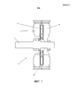
фиг. 1 представляет собой условную схему электрической машины с осевым магнитным потоком, включающей в себя ротор в соответствии с предпочтительным вариантом осуществления настоящего изобретения;FIG. 1 is a schematic diagram of an axial magnetic flux electric machine incorporating a rotor in accordance with a preferred embodiment of the present invention;
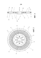
фиг. 2 - представляет собой вид в плане ротора в соответствии с предпочтительным вариантом осуществления настоящего изобретения;FIG. 2 is a plan view of a rotor in accordance with a preferred embodiment of the present invention;
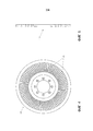
фиг. 3 - представляет собой вид поперечного сечения ротора по фиг. 2;FIG. 3 is a cross-sectional view of the rotor of FIG. 2;
фиг. 4 - представляет собой вид в плане ротора в соответствии с другим предпочтительным вариантом осуществления настоящего изобретения;FIG. 4 is a plan view of a rotor in accordance with another preferred embodiment of the present invention;
фиг. 5 - представляет собой вид поперечного сечения ротора по фиг. 4;FIG. 5 is a cross-sectional view of the rotor of FIG. four;
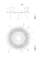
фиг. 6 - представляет собой вид в плане ротора в соответствии с другим предпочтительным вариантом осуществления настоящего изобретения; иFIG. 6 is a plan view of a rotor in accordance with another preferred embodiment of the present invention; and
фиг. 7 - представляет собой вид поперечного сечения ротора по фиг. 6.FIG. 7 is a cross-sectional view of the rotor of FIG. 6
Описание вариантов осуществленияDescription of embodiments
Следует отметить, что в нижеследующем описании одинаковые или одни и те же ссылочные позиции в разных вариантах осуществления обозначают одни и те же или подобные признаки.It should be noted that in the following description, the same or the same reference numbers in different embodiments denote the same or similar signs.
Изобретение относится к ротору 10 для индукционной электрической машины 12 с осевым магнитным потоком. Обратимся к фиг. 1, - машина 100) включает в себя первый статор 14 и второй статор 16, находящийся в симметричном зеркальном положении к первому статору 14 таким образом, что между первым и вторым статорами 14, 16 определен промежуточный зазор 18. В зазоре 18 расположен ротор 10 в форме тонкого кольцевого диска. Толщина диска существенно меньше, чем радиус диска.The invention relates to a
Обратимся к фиг. 2 и 3, - конструкция 10 ротора состоит из центральной рамки 20 из ферромагнитного материала и двух наружных рамок 22, 24 из неферромагнитных материалов, прикрепленных к противоположным поверхностям 26, 28 центральной рамки 20.Referring to FIG. 2 and 3, the
Неферромагнитные рамки 22, 24 изготовлены из материала с высокой электрической проводимостью, такого как алюминий или медь. Неферромагнитные рамки 22, 24 содержат внутреннюю краевую область 32 и внешнюю краевую область 34. С краевыми областями 32, 34 гальванически соединены электропроводящие перемычки 36, изготовленные из такого же материала. Эти электропроводящие перемычки 36 вместе с внутренней и внешней краевыми областями 32, 34 образуют обмотку ротора 10 типа "беличья клетка". Как это показано, электропроводящие перемычки 36 упорядочены, продолжаясь в радиальном направлении от внутренней краевой области 32 до внешней краевой области 34. Однако будут работать также и другие конфигурации электропроводящих перемычек. Например, фиг. 4 и 5 показывают альтернативный вариант осуществления ротора 110, в котором электропроводящие перемычки 136 имеют наклонную конфигурацию.The
Количество электропроводящих перемычек 36 идеально подбирают на основе их отношения к количеству пазов на статоре 14, 16. Обнаружено, что имея это отношение высоким (то есть большее количество электропроводящих перемычек по сравнению с количеством пазов статора), обеспечивается уменьшение разностной утечки по сравнению с использованием низкого отношения. Было найдено, что идеальное отношение составляет 1,666:1. В показанном варианте осуществления это отношение соответствует 80 электропроводящим перемычкам для использования со статором, имеющим 48 статорных пазов.The number of electrically
Конструкция неферромагнитных рамок 22, 24 обеспечивает промежуточные участки 38, определенные между соседними электропроводящим перемычкам 36 и внутренними 32 и внешними краевыми областями 34.The design of the
Для того чтобы обеспечить дисковый ротор 10 с высоким уровнем конструктивной жесткости, чтобы ротор 10 мог сохранять размерную устойчивость и выдерживал как осевые, так и радиальные конструктивные напряжения и напряжение моментов вращения, центральная рамка 20 изготовлена из такого ферромагнитного материала, как сталь. Эта ферромагнитная рамка 20 выполнена интегрально в виде одного цельного элемента.In order to provide a
На сторонах 26, 28, противоположных центральной рамке 20, от рамки 20 продолжаются сформированные как одно целое (интегрально) фасонные выступы 40. Выступы 40 показаны как имеющие клиновидную форму, которая соответствует форме участков 38 зазоров в неферромагнитных рамках 22, 24.On the
Неферромагнитные рамки 22, 24 размещены, соответственно, на каждой из сторон 26, 28 центральной рамки 20 с клиновидными выступами 40, входящие в участки 38 зазоров неферромагнитных рамок 22, 24 и проходящими через них. Неферромагнитные рамки 22, 24 могут быть закреплены по месту, например, с использованием подходящей эпоксидной смолы.Non-ferromagnetic frames 22, 24 are placed, respectively, on each of the
Такая конфигурация повышает пропускную способность ротора 10 по магнитному потоку и обеспечивает путь магнитному потоку между первым и вторым статорами 14, 16, обусловленный множеством ферромагнитных клиновидных выступов 40, проходящих через неферромагнитные рамки 22, 24 и удаленных один от другого на соответствующее расстояние, такое, что между выступами 40 должным образом расположены неферромагнитные электропроводящие перемычки 36.This configuration increases the magnetic flux throughput of the
Центральная рамка 20 имеет центральное отверстие 42, в которое входит отдельный элемент ступицы. Элемент ступицы используется для крепления ротора, который должен быть установлен на валу 11 электрической машины 12, например, с помощью радиальных установочных винтов и шпонки вала. Центральное отверстие 42 окружают несколько дополнительных отверстий 44 для приема болтов, винтов или других подходящих средств, чтобы крепить ротор 10 к ступице.The
На, проиллюстрированных на фиг. с 4 по 7 альтернативных вариантах осуществления ступица не показана.On, illustrated in FIG. 4 through 7 alternative embodiments, the hub is not shown.
Фиг. 6 и 7 показывают альтернативный вариант осуществления ротора 210. В этом варианте осуществления неферромагнитные рамки 222, 224 имеют промежуточный участок 250, расположенный между внутренней краевой областью 232 и внешней краевой областью 234. Электропроводящие перемычки 236 продолжаются между внутренней краевой областью 232 и промежуточным участком 250, а также между промежуточным участком 250 и внешней краевой областью 234. И снова, - эта конфигурация обеспечивает участки 238 зазоров, а центральная рамка 220 имеет выступы 240, которым придана комплементарная форма, предназначенные для вставки их в участки 238 зазоров и прохождения сквозь них. При испытаниях было обнаружено, что ротор 210, включающий в себя промежуточный участок 250, повышает характеристики, обеспечивая улучшенную магнитную цепь и уменьшенную пульсацию крутящего момента.FIG. 6 and 7 show an alternative embodiment of the
Ферромагнитные и неферромагнитные части 20, 22, 24 ротора могут быть изготовлены из листового металла с использованием методов удаления материала с помощью фрезерования, лазерной резки, резки водяной струей или посредством обработки электрическим разрядом. Альтернативно, части 20, 22, 24 ротора могут быть изготовлены с использованием методов прямого металлического спекания трехмерной печати.Ferromagnetic and
В предпочтительных вариантах осуществления центральная рамка 20 образована литьевым процессом. В принципе неферромагнитные рамки 22, 24 могли бы быть образованы литьем под давлением на центральную ферромагнитную рамку 20, используя эту ферромагнитную раму как форму внутри литьевой инструментальной формы.In preferred embodiments, the implementation of the
ИнтерпретацияInterpretation
Варианты осуществленияEmbodiments
Ссылка по всему данному описанию на "один вариант осуществления" или на "вариант осуществления" означает, что конкретный признак, элемент конструкции или характеристика, описанные в связи с этим вариантом осуществления, включены, по меньшей мере, в один вариант осуществления настоящего изобретения. Таким образом, наличие в разных местах по всему данному описанию фраз "в одном варианте осуществления" или "в варианте осуществления" не обязательно относится - но может относиться - к одному и тому же варианту осуществления. Кроме того, конкретные признаки, элементы конструкции или характеристики могут быть объединены любым подходящим способом в одном или нескольких вариантах осуществления, как это было бы очевидно специалисту в данной области техники из данного описания.Reference throughout this specification to “one embodiment” or to “an embodiment” means that a particular feature, component or characteristic described in connection with this embodiment is included in at least one embodiment of the present invention. Thus, the presence of phrases "in one embodiment" or "in an embodiment" in different places throughout this description does not necessarily refer to - but may refer to - the same embodiment. In addition, specific features, structural elements or characteristics can be combined in any suitable way in one or more embodiments, as would be obvious to a person skilled in the art from this description.
Аналогичным образом, - следует понимать, что в вышеприведенном описании примерных вариантов осуществления изобретения различные признаки изобретения иногда сгруппированы вместе в одном варианте осуществления, чертеже или его описании с целью упрощения описания и способствования пониманию одного или более из различных объектов изобретения. Однако этот способ раскрытия изобретения не должен интерпретироваться как отражающий намерение, в соответствии с которым заявленное изобретение требует большего количества признаков, чем это явно указано в каждом пункте формулы изобретения. Скорее, как это следует из нижеследующих пунктов, объекты изобретения заключены не во всех признаках одного изложенного выше раскрытого варианта осуществления. Таким образом, пункты формулы изобретения, следующие за разделом Подробное описание конкретных вариантов осуществления, явно включены в этот раздел, при этом каждый пункт формулы изобретения сам по себе выступает в качестве отдельного варианта осуществления настоящего изобретения.Similarly, it should be understood that in the above description of exemplary embodiments of the invention, various features of the invention are sometimes grouped together in one embodiment, drawing, or description thereof in order to simplify the description and facilitate understanding of one or more of the various objects of the invention. However, this method of disclosure of the invention should not be interpreted as reflecting the intention, according to which the claimed invention requires a larger number of features than is explicitly indicated in each claim. Rather, as follows from the following paragraphs, the objects of the invention are not enclosed in all features of one of the disclosed embodiment described above. Thus, the claims following the Detailed Description of Specific Embodiments are explicitly included in this section, with each claim of the invention itself serving as a separate embodiment of the present invention.
Кроме того, хотя описанные здесь некоторые варианты осуществления включают в себя одни признаки, но не включают другие, включенные в другие варианты осуществления, предполагается, что сочетания признаков различных вариантов осуществления находятся в рамках объема изобретения и составляют другие варианты осуществления, как это понятно специалистам в данной области техники. Например, в нижеследующих пунктах формулы изобретения любой из заявленных вариантов осуществления может использоваться в любой комбинации.In addition, although some embodiments described herein include some features, but do not include others included in other embodiments, it is assumed that combinations of features of various embodiments are within the scope of the invention and constitute other embodiments, as is clear to experts in this area of technology. For example, in the following claims, any of the claimed embodiments may be used in any combination.
Различные примеры задачVarious examples of tasks
В том смысле, как они здесь используются, если не указано иное, использование порядковых прилагательных "первый", "второй", "третий" и т. д. для описания общего объекта просто указывает на то, что упоминаются разные позиции схожих объектов, и при этом нет намерения указывать, что описанные таким образом объекты должны быть расположены в данной последовательности - во времени, пространственно, в порядке значимости или любым иным образом.In the sense that they are used here, unless otherwise indicated, the use of ordinal adjectives "first", "second", "third", etc., to describe a common object simply indicates that different positions of similar objects are mentioned, and however, it is not intended to indicate that the objects described in this way should be arranged in a given sequence — in time, spatially, in order of importance, or in any other way.
Конкретные деталиSpecific details
В приведенном здесь описании представлены многочисленные конкретные детали. Однако понятно, что на практике варианты осуществления изобретения могут быть осуществлены без этих конкретных деталей. В других случаях хорошо известные методы, конструкции и способы, чтобы не затруднять понимание этого описания, не были показаны подробно.The description here provides numerous specific details. However, it is clear that in practice, embodiments of the invention can be implemented without these specific details. In other cases, well-known methods, constructions and methods, so as not to obscure the understanding of this description, were not shown in detail.
ТерминологияTerminology
При описании проиллюстрированного на чертежах предпочтительного варианта осуществления изобретения ради ясности использована специальная терминология. Однако нет намерения ограничивать изобретение выбранными таким образом специальными терминами, и следует понимать, что каждый специальный термин включает в себя все технические эквиваленты, которые несут в себе подобный же смысл для достижения аналогичной технической цели. Такие термины, как "вперед", "назад", "радиально", "по периферии", "вверх", "вниз" и т. д., используются в качестве удобных слов для определения опорных точек и не должны рассматриваться как ограничивающие термины.When describing the preferred embodiment of the invention illustrated in the drawings, for the sake of clarity, special terminology is used. However, there is no intention to limit the invention to the specific terms chosen in this way, and it should be understood that each special term includes all technical equivalents that carry a similar meaning for achieving a similar technical goal. Terms such as “forward”, “backward”, “radially”, “peripheral”, “upward”, “downward”, etc., are used as convenient words for defining anchor points and should not be construed as limiting terms. .
"Содержащий" и "включающий в себя""Inclusive" and "Inclusive"
В нижеследующих пунктах формулы изобретения, а также в предшествующем описании изобретения, за исключением тех случаев, когда контекст требует иного, чтобы выразить языковыми средствами необходимый смысл, слово "содержать" или его варианты, такие как "содержит" или "содержащий", используются в инклюзивном смысле, то есть, для того чтобы определять наличие указанных признаков, но не исключать наличия или добавления дополнительных признаков в различных вариантах осуществления изобретения.In the following claims, as well as in the foregoing description of the invention, unless the context requires something else to express the necessary meaning in the language means, the word "contain" or its variants, such as "contains" or "containing", are used in inclusive sense, that is, in order to determine the presence of these features, but not exclude the presence or addition of additional features in various embodiments of the invention.
Любой из терминов, "включающий", "который включает в себя" или "что включает в себя", в том смысле, как он здесь используется, также является открытым термином, который также означает включение, по меньшей мере, элементов или признаков, которые следуют за этим термином, но не исключая других. Таким образом, "включающий в себя" означает "содержащий" и является его синонимом.Any of the terms "including", "which includes" or "what includes", in the sense it is used here, is also an open term, which also means the inclusion of at least elements or features that follow this term, but not excluding others. Thus, "including" means "containing" and is its synonym.
Объем изобретенияScope of invention
Таким образом, хотя здесь описано то, что, как представляется, является предпочтительными вариантами осуществления изобретения, специалисты в данной области техники поймут, что в них могут быть внесены другие, дополнительные изменения, не выходящие за рамки сущности изобретения, и что все такие изменения и модификации как входящие в объем настоящего изобретения могут притязать на изобретение. Например, любые вышеприведенные формулировки просто представляют процедуры, которые могут быть осуществлены. В блок-схемы могут добавляться выполняемые функции, или же выполняемые функции могут из них удаляться, а операции могут быть взаимозаменяемыми между функциональными блоками. Внутри способов, описанных в рамках объема настоящего изобретения, этапы могут добавляться и удаляться.Thus, although what is described here seems to be preferred embodiments of the invention, those skilled in the art will understand that other, additional changes may be made to them, without departing from the gist of the invention, and that all such changes and modifications as included in the scope of the present invention may claim the invention. For example, any of the above formulations simply represent procedures that can be implemented. Functions can be added to flowcharts, or functions that can be performed can be removed from them, and operations can be interchanged between functional blocks. Within the methods described within the scope of the present invention, steps may be added and removed.
Хотя изобретение описано со ссылкой на конкретные примеры, специалистам в данной области будет понятно, что изобретение может быть реализовано во многих других формах.Although the invention has been described with reference to specific examples, it will be understood by those skilled in the art that the invention can be implemented in many other forms.
Промышленная применимостьIndustrial Applicability
Из вышеизложенного очевидно, что описанные конфигурации применимы в отраслях промышленности, связанных с электрическими машинами.From the foregoing it is obvious that the described configurations are applicable in industries related to electrical machines.
Claims (36)
Applications Claiming Priority (2)
| Application Number | Priority Date | Filing Date | Title |
|---|---|---|---|
| AU2014900988A AU2014900988A0 (en) | 2014-03-21 | Disc rotor for an axial flux induction electrical machine | |
| PCT/AU2015/000165 WO2015139080A1 (en) | 2014-03-21 | 2015-03-20 | Rotor for an electrical machine |
Publications (2)
| Publication Number | Publication Date |
|---|---|
| RU2017134487A RU2017134487A (en) | 2019-04-04 |
| RU2685544C2 true RU2685544C2 (en) | 2019-04-22 |
Family
ID=54143542
Family Applications (1)
| Application Number | Title | Priority Date | Filing Date |
|---|---|---|---|
| RU2017134487A RU2685544C2 (en) | 2014-03-21 | 2015-03-20 | Rotor for electric machine |
Country Status (12)
| Country | Link |
|---|---|
| US (1) | US10651712B2 (en) |
| EP (1) | EP3271998A4 (en) |
| JP (1) | JP6839667B2 (en) |
| KR (1) | KR20170125966A (en) |
| CN (1) | CN107534371B (en) |
| BR (1) | BR112017020080A2 (en) |
| CA (1) | CA2980194C (en) |
| HK (1) | HK1249669A1 (en) |
| MX (1) | MX2017012221A (en) |
| MY (1) | MY186626A (en) |
| RU (1) | RU2685544C2 (en) |
| WO (1) | WO2015139080A1 (en) |
Families Citing this family (6)
| Publication number | Priority date | Publication date | Assignee | Title |
|---|---|---|---|---|
| EP3288159A1 (en) * | 2016-08-24 | 2018-02-28 | Siemens Aktiengesellschaft | Bypass rotor in particular for high rotational speeds |
| US11031835B2 (en) | 2019-03-27 | 2021-06-08 | Roderick James Brogan | Axial flux induction motor or generator |
| CN111446820A (en) * | 2019-12-31 | 2020-07-24 | 太原科技大学 | Device and method for measuring rotor rotation speed based on 3D printing technology by direct method |
| CN111740517B (en) * | 2020-07-31 | 2021-08-20 | 江苏华力易电科技有限公司 | Rotor of disc type asynchronous motor and motor with same |
| CN113794339B (en) * | 2021-09-18 | 2022-09-02 | 上海盘毂动力科技股份有限公司 | Method for forming integrated assembly with rotating shaft and rotor disc |
| DE102022004796A1 (en) | 2022-12-19 | 2023-02-23 | Mercedes-Benz Group AG | Electric machine for a motor vehicle and motor vehicles |
Citations (6)
| Publication number | Priority date | Publication date | Assignee | Title |
|---|---|---|---|---|
| US5907210A (en) * | 1995-09-29 | 1999-05-25 | Technicatome Societe Technique Pour L'energie Atomique | Asynchronous discoidal electrical motor |
| RU2173926C1 (en) * | 2000-02-03 | 2001-09-20 | Забора Игорь Георгиевич | Electric motor for sealed objects |
| US6809453B2 (en) * | 2002-07-17 | 2004-10-26 | Fujitsu General Limited | Induction motor |
| JP2006345627A (en) * | 2005-06-08 | 2006-12-21 | Nissan Motor Co Ltd | Rotor structure of rotary electric machine |
| JP2011172385A (en) * | 2010-02-18 | 2011-09-01 | Daikin Industries Ltd | Axial gap motor and compressor |
| US8294322B2 (en) * | 2008-03-28 | 2012-10-23 | Toyota Jidosha Kabushiki Kaisha | Rotating electrical machine |
Family Cites Families (21)
| Publication number | Priority date | Publication date | Assignee | Title |
|---|---|---|---|---|
| US1605796A (en) | 1926-11-02 | Electric machine | ||
| US2469808A (en) * | 1946-09-28 | 1949-05-10 | Gen Mills Inc | Induction motor rotor |
| US3296475A (en) * | 1965-09-15 | 1967-01-03 | Louis W Parker | Dynamo-electric machines, and rotors therefor |
| JPS58190261A (en) * | 1982-04-27 | 1983-11-07 | Toshiba Corp | Flat induction motor |
| JPS60152259A (en) * | 1984-01-20 | 1985-08-10 | Nissan Motor Co Ltd | Manufacture of core for motor |
| DE3891337T1 (en) * | 1988-06-01 | 1990-06-07 | Pal Adam | ROTATING ELECTRICAL MACHINE WITH IRON CORE DISC ARMATURE |
| DE19541737A1 (en) * | 1995-11-09 | 1997-05-15 | Philips Patentverwaltung | Axial flow induction motor |
| US5861700A (en) * | 1996-04-30 | 1999-01-19 | Samsung Electronics Co., Ltd. | Rotor for an induction motor |
| JP4337961B2 (en) * | 1999-06-24 | 2009-09-30 | 哲夫 関谷 | Electrical energy converter |
| GB2358523A (en) * | 1999-12-21 | 2001-07-25 | Richard Fletcher | Electronically commutated electrical machine |
| US7067950B2 (en) * | 2003-01-31 | 2006-06-27 | Light Engineering, Inc. | Efficient high-speed electric device using low-loss materials |
| FI20041113A0 (en) * | 2004-08-25 | 2004-08-25 | Juha Pyrhoenen | Axialflödesinduktionselmaskin |
| GB0800225D0 (en) * | 2008-01-07 | 2008-02-13 | Evo Electric Ltd | A rotor for an electrical machine |
| JP5175126B2 (en) * | 2008-03-24 | 2013-04-03 | 株式会社豊田中央研究所 | Rotating electrical machine rotor and rotating electrical machine |
| US7741750B1 (en) * | 2008-12-29 | 2010-06-22 | Tesla Motors, Inc. | Induction motor with improved torque density |
| JP2011147257A (en) * | 2010-01-14 | 2011-07-28 | Emaajii:Kk | Induction motor |
| US20120212085A1 (en) * | 2011-02-17 | 2012-08-23 | The Hong Kong Polytechnic University | Axial-flux electric machine |
| US8726490B2 (en) * | 2011-08-18 | 2014-05-20 | Glassy Metal Technologies Ltd. | Method of constructing core with tapered pole pieces and low-loss electrical rotating machine with said core |
| JP6134126B2 (en) * | 2012-11-20 | 2017-05-24 | 株式会社東芝 | Rotating electric machine and vehicle |
| WO2014079881A2 (en) * | 2012-11-20 | 2014-05-30 | Jaguar Land Rover Limited | Electric machine and method of operation thereof |
| JP6158022B2 (en) * | 2013-09-30 | 2017-07-05 | 株式会社東芝 | Rotating electric machine and vehicle |
-
2015
- 2015-03-20 RU RU2017134487A patent/RU2685544C2/en active
- 2015-03-20 US US15/560,152 patent/US10651712B2/en active Active
- 2015-03-20 JP JP2017567507A patent/JP6839667B2/en active Active
- 2015-03-20 BR BR112017020080A patent/BR112017020080A2/en not_active Application Discontinuation
- 2015-03-20 EP EP15764354.5A patent/EP3271998A4/en not_active Ceased
- 2015-03-20 MY MYPI2017703478A patent/MY186626A/en unknown
- 2015-03-20 CA CA2980194A patent/CA2980194C/en active Active
- 2015-03-20 WO PCT/AU2015/000165 patent/WO2015139080A1/en active Application Filing
- 2015-03-20 KR KR1020177029279A patent/KR20170125966A/en active IP Right Grant
- 2015-03-20 MX MX2017012221A patent/MX2017012221A/en active IP Right Grant
- 2015-03-20 CN CN201580079642.8A patent/CN107534371B/en active Active
-
2018
- 2018-07-13 HK HK18109121.3A patent/HK1249669A1/en unknown
Patent Citations (6)
| Publication number | Priority date | Publication date | Assignee | Title |
|---|---|---|---|---|
| US5907210A (en) * | 1995-09-29 | 1999-05-25 | Technicatome Societe Technique Pour L'energie Atomique | Asynchronous discoidal electrical motor |
| RU2173926C1 (en) * | 2000-02-03 | 2001-09-20 | Забора Игорь Георгиевич | Electric motor for sealed objects |
| US6809453B2 (en) * | 2002-07-17 | 2004-10-26 | Fujitsu General Limited | Induction motor |
| JP2006345627A (en) * | 2005-06-08 | 2006-12-21 | Nissan Motor Co Ltd | Rotor structure of rotary electric machine |
| US8294322B2 (en) * | 2008-03-28 | 2012-10-23 | Toyota Jidosha Kabushiki Kaisha | Rotating electrical machine |
| JP2011172385A (en) * | 2010-02-18 | 2011-09-01 | Daikin Industries Ltd | Axial gap motor and compressor |
Also Published As
| Publication number | Publication date |
|---|---|
| US20180097428A1 (en) | 2018-04-05 |
| CA2980194C (en) | 2021-11-23 |
| KR20170125966A (en) | 2017-11-15 |
| US10651712B2 (en) | 2020-05-12 |
| EP3271998A1 (en) | 2018-01-24 |
| CA2980194A1 (en) | 2015-09-24 |
| HK1249669A1 (en) | 2018-11-02 |
| EP3271998A4 (en) | 2018-12-05 |
| CN107534371B (en) | 2019-12-10 |
| BR112017020080A2 (en) | 2018-06-05 |
| JP2018509133A (en) | 2018-03-29 |
| RU2017134487A (en) | 2019-04-04 |
| MX2017012221A (en) | 2018-06-19 |
| WO2015139080A1 (en) | 2015-09-24 |
| CN107534371A (en) | 2018-01-02 |
| JP6839667B2 (en) | 2021-03-10 |
| MY186626A (en) | 2021-07-31 |
Similar Documents
| Publication | Publication Date | Title |
|---|---|---|
| RU2685544C2 (en) | Rotor for electric machine | |
| CA2894788C (en) | Permanent magnet machine with segmented sleeve for magnets | |
| US7355311B2 (en) | Rotor of axial gap motor and method of producing same | |
| US10879778B2 (en) | Rotor of rotating electric machine and manufacturing method of the same | |
| US8541918B2 (en) | Rotating electrical machine and method of manufacturing the rotating electrical machine | |
| US7714478B2 (en) | Electric rotary machine | |
| US20150295462A1 (en) | Rotor for a rotary electric machine | |
| US9935509B2 (en) | Rotary electric machine rotor | |
| WO2017071470A1 (en) | Large power disc-type electric generator | |
| US20160134169A1 (en) | Stator assembly unit of drive motor of hybrid vehicle | |
| US20150123506A1 (en) | Modular permanent magnet motor and pump assembly | |
| US20190052138A1 (en) | Rotor assembly and motor including the same | |
| CN107707042A (en) | Motor | |
| JP2015204653A (en) | Rotary electric machine | |
| US10938280B2 (en) | Flux shield for electric motor | |
| JP5360224B2 (en) | Method for manufacturing electric motor rotor | |
| KR102269299B1 (en) | Rotor including segmented yoke | |
| EP3402044A1 (en) | Magnet module and method of manufacturing same | |
| JP7212587B2 (en) | Axial gap type rotary electric machine | |
| JP2011109786A (en) | Electric motor rotor | |
| FI127275B (en) | Scooters for a radial turbine and process for making them | |
| US10720804B2 (en) | Permanent magnet machine with segmented sleeve for magnets | |
| KR101208318B1 (en) | Motor rotor for automobile | |
| US20170324287A1 (en) | Rotor, Synchronous Machine And Hybrid Drive | |
| RU40690U1 (en) | ROTOR PLATE |
Legal Events
| Date | Code | Title | Description |
|---|---|---|---|
| RH4A | Copy of patent granted that was duplicated for the russian federation |
Effective date: 20200427 |