US7714478B2 - Electric rotary machine - Google Patents
Electric rotary machine Download PDFInfo
- Publication number
- US7714478B2 US7714478B2 US11/797,845 US79784507A US7714478B2 US 7714478 B2 US7714478 B2 US 7714478B2 US 79784507 A US79784507 A US 79784507A US 7714478 B2 US7714478 B2 US 7714478B2
- Authority
- US
- United States
- Prior art keywords
- stator
- rotor
- rotary machine
- electric rotary
- case
- Prior art date
- Legal status (The legal status is an assumption and is not a legal conclusion. Google has not performed a legal analysis and makes no representation as to the accuracy of the status listed.)
- Active, expires
Links
Images


Classifications
-
- H—ELECTRICITY
- H02—GENERATION; CONVERSION OR DISTRIBUTION OF ELECTRIC POWER
- H02K—DYNAMO-ELECTRIC MACHINES
- H02K21/00—Synchronous motors having permanent magnets; Synchronous generators having permanent magnets
- H02K21/12—Synchronous motors having permanent magnets; Synchronous generators having permanent magnets with stationary armatures and rotating magnets
- H02K21/24—Synchronous motors having permanent magnets; Synchronous generators having permanent magnets with stationary armatures and rotating magnets with magnets axially facing the armatures, e.g. hub-type cycle dynamos
-
- H—ELECTRICITY
- H02—GENERATION; CONVERSION OR DISTRIBUTION OF ELECTRIC POWER
- H02K—DYNAMO-ELECTRIC MACHINES
- H02K3/00—Details of windings
- H02K3/46—Fastening of windings on the stator or rotor structure
- H02K3/52—Fastening salient pole windings or connections thereto
- H02K3/521—Fastening salient pole windings or connections thereto applicable to stators only
- H02K3/524—Fastening salient pole windings or connections thereto applicable to stators only for U-shaped, E-shaped or similarly shaped cores
-
- H—ELECTRICITY
- H02—GENERATION; CONVERSION OR DISTRIBUTION OF ELECTRIC POWER
- H02K—DYNAMO-ELECTRIC MACHINES
- H02K5/00—Casings; Enclosures; Supports
- H02K5/04—Casings or enclosures characterised by the shape, form or construction thereof
-
- H—ELECTRICITY
- H02—GENERATION; CONVERSION OR DISTRIBUTION OF ELECTRIC POWER
- H02K—DYNAMO-ELECTRIC MACHINES
- H02K5/00—Casings; Enclosures; Supports
- H02K5/04—Casings or enclosures characterised by the shape, form or construction thereof
- H02K5/20—Casings or enclosures characterised by the shape, form or construction thereof with channels or ducts for flow of cooling medium
- H02K5/203—Casings or enclosures characterised by the shape, form or construction thereof with channels or ducts for flow of cooling medium specially adapted for liquids, e.g. cooling jackets
Definitions
- the present invention relates to an electric rotary machine in which a magnetic circuit (or a magnetic path) is formed between a rotor and a stator, and, more specifically, relates to a technique in the electric rotary machine which prevents a reduction of a driving efficiency generated due to an overflow of the magnetic path from a naturally ideal position of the magnetic path.
- the previously proposed electric rotary machine disclosed in the above-described Japanese Patent Application Publication houses a rotor and the stator in an internal spatial region of a case made of an aluminum alloy. Cooling fins are attached on an external of the case.
- the stator is attached in an inside of the case.
- the stator is laminated with a plurality of thin-plate steel plates and non electrically conductive nonferrous layers.
- the stator minimizes a loss due to an eddy current of a magnetic flux at the inside of the stator.
- the stator is partitioned by means of thirty-six (36) grooves in a peripheral direction of the stator.
- the stator has the same number of stator cores as that of the grooves.
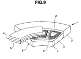
- FIG. 9 shows a partially cross sectioned perspective view of the comparative example of the axial gap electric rotary machine in which both of the rotor and the stator are arranged in an axial direction.
- a reference symbol A denotes a part of the rotor and a reference symbol B denotes a part of the stator.
- Rotor A and stator B are separately opposed by a slightly short distance from each other in the axial direction of the electric rotary machine.
- a clearance between rotor A and stator B is called a gap.
- Each of permanent magnets C is adhered onto a front surface of both front and rear surfaces of a circular plate-like rotor A which opposes against stator B via the gap.
- Coil windings E are wound on surroundings of respective stator cores D.
- An inner peripheral ring F is arranged at an inner part of stator cores D in a radial direction of stator B.
- An outer peripheral ring G is arranged at an outer part of stator cores D in the radial direction thereof.
- thin-plate materials H, H,—extended in the radial direction connect these rings F, G together and serve to couple these inner and outer peripheral rings F, G to each other.
- Each of these rings F, G and thin-plate materials H is formed of a light metal such as aluminum or duralumin.
- These members F, G, H are united into one body to constitute a metallic supporting member. This metallic supporting member constitutes a framework of stator B and the electric rotary machine.
- a structural rigidity (or a structural strength) of the electric rotary machine is secured.
- Each stator core D on which coil winding E is wound is arranged between circumferentially and mutually abutting thin-plate material H, H and between rings F, G.
- a resin is filled on an outer periphery of each coil winding E to assure a fixing of each coil winding E between thin-plate H and rings F, G.
- the magnetic fluxes from stator cores D and from permanent magnets C form the magnetic path via the gap between rotor A and stator B.
- a torque is given to rotor A to rotate rotor A.
- FIG. 10 shows a perspective view of inner peripheral ring F and of outer peripheral ring G as viewed from an arrow-marked direction in FIG. 9 .
- a distribution of a magnetic flux density of the leakage magnetic flux passing through inner peripheral ring F and outer peripheral ring G which are not the stator nor the rotor is divided into a plurality of zones on the magnetic flux density, when the axial gap electric rotary machine of the above-described comparative example is driven in an acceleration state.
- a zone 4 indicates a large magnetic flux density and the magnetic flux densities become smaller in an order of a zone 3 , a zone 2 , and a zone 1 .
- the magnetic flux density is not varied in a stepwise manner for each portion shown in a zone division but the magnetic flux density is distributed so as to be varied in continuous and progressive manners from a portion at which the magnetic flux density is relatively large to a portion at which the magnetic flux density is relatively small.
- FIG. 11 shows a distribution of eddy current densities caused by the leakage magnetic flux described above divided into a plurality of zones.
- a zone 4 ′ indicates a large eddy current density and the eddy current densities become smaller in an order of a zone 3 ′, a zone 2 ′, and a zone 1 ′.
- the eddy current density is not varied in a stepwise manner for each portion shown in the zone division but the eddy current density is distributed so as to be varied in continuous and progressive manners from a portion at which the eddy current density is relatively large to a portion at which the eddy current density is relatively small. As shown in FIG.
- the eddy current density becomes larger as the portion of each member becomes nearer to the gap.
- the eddy current density becomes larger as the portion of each member becomes nearer to the magnetic pole of each stator core D which faces against the gap and to the magnetic pole of each permanent magnet C which faces the gap.
- an electric rotary machine comprising: a stator; a metallic supporting member configured to support the stator; and a rotor, the rotor being relatively rotatably supported to the stator, a magnetic path being formed via a gap portion between the stator and the rotor to give a torque to the rotor, and a space section being provided on a portion of the metallic supporting member near a magnetic pole of the stator facing the gap portion to interrupt the magnetic path.
- a space section has a large magnetic resistance and the magnetic flux becomes difficult to pass through the space section. Hence, the passage of the magnetic flux through the metallic supporting member can largely be eliminated.
- FIG. 1 is a longitudinal cross sectional view of a preferred embodiment of an electric rotary machine according to the present invention partially cut away with a plane including an axial line.
- FIG. 2 is a longitudinal cross sectional view of another preferred embodiment of the electric rotary machine according to the present invention partially cut away with the plane including the axial line.
- FIG. 3 is a perspective view of a case of the electric rotary machine in a still another preferred embodiment according to the present invention with the case partially broken.
- FIG. 4 is a perspective view of a part of the case of the electric rotary machine in a further another preferred embodiment according to the present invention with a part of the case broken.
- FIG. 5 is a cross sectional view of the part of the case shown in FIG. 4 cut away along a line of A-A in FIG. 4 .
- FIG. 6 is a cross sectional view of the part of the case shown in FIG. 4 cut away along a line of B-B in FIG. 4 .
- FIG. 7 is a perspective view of the case and an inner peripheral ring in the further other preferred embodiment of the electric rotary machine representing a result of analysis of a distribution of magnetic fluxes of the inner peripheral ring and the case in the further another preferred embodiment under the same condition as a model shown in FIG. 9 .
- FIG. 8 is a perspective view of the case and the inner peripheral ring in the further other preferred embodiment of the electric rotary machine representing a result of analysis of a distribution of eddy current densities of the inner peripheral ring and the case in the further other preferred embodiment under the same condition as a model shown in FIG. 9 .
- FIG. 9 is a partially cross sectioned perspective view of an analytical model which is a comparative example of an axial gap electric rotary machine in which a rotor and a stator are arranged in an axial direction to the present invention.
- FIG. 10 is a perspective view representing a magnetic flux density distribution of the inner peripheral ring and an outer peripheral ring in the analytical model shown in FIG. 9 .
- FIG. 11 is a perspective view representing an eddy current density distribution of the inner peripheral ring and an outer peripheral ring in the analytical model shown in FIG. 9 .
- FIG. 1 shows a longitudinal cross sectional view of a stator in a preferred embodiment of an electric rotary machine according to the present invention, partially cut away with a plane including an axial line.
- rotors 6 are arranged at both sides of a stator 5 in a direction of an axle O so as to oppose with each other via stator 5 .
- a gap portion 7 is provided between each of rotors 6 and stator 5 .
- a case 8 made of aluminum is installed on an outer periphery of stator 5 .
- Case 8 may be made of a metallic raw material having a high strength (rigidity), a light weight, and a high thermal conductivity, other than the aluminum raw material.
- Case 8 is a hollow cylindrical member with axle 0 as a center.
- Stator cores 9 are attached onto an inner wall 8 u located at an inner peripheral surface of the hollow cylindrical member, viz., case 8 .
- a plurality of stator cores 9 are arranged in a peripheral direction of axle O and each of stator cores 9 is extended in the direction of axle O.
- stator cores 9 Widths of both ends 9 t , 9 t of stator cores 9 in the direction of axle O are extended to secure areas of stator cores 9 abutting gap portion 7 .
- Coil windings 10 are wound around a middle portion of stator cores 9 located between both ends 9 t , 9 t .
- Insulators 14 are attached onto both ends of coil windings 10 in the direction of axle O. Insulators 14 serve to secure the fixing of the ends of coil windings 10 in the direction of axle O onto the outer periphery of stator cores 9 .
- Stator cores 9 and coil windings 10 constitute an armature.
- a hollow cylindrical shaped inner peripheral ring 11 is arranged in an inner diameter direction of each of stator cores 9 .
- Inner peripheral ring 11 is made of aluminum and a shaft (not shown) extended along the direction of axle O and coupled with each rotor 6 is penetrated through a center hole 11 c formed by an inner wall of inner peripheral ring 11 .
- Outer walls 11 s of inner peripheral ring 11 are coupled with inner walls 8 u of case 8 via thin plate members 12 extended in the radial direction of stator 5 .
- Theses thin plate members 12 are alternately arranged with respective stator cores 9 in the peripheral (circumferential) direction of axle O.
- Stator cores 9 on which coil windings 10 are wound are disposed between mutually adjacent case 8 and inner peripheral ring 11 in the radial direction and between mutually adjacent thin plate members 12 , 12 in the peripheral direction.
- This disposition method is as follows: That is to say, a projection 23 such as a terminal projected from each of coil windings 10 is, at first, preliminarily fixed to each of outer walls 11 s of inner peripheral ring 11 by means of a resin 21 . At the next stage, a resin 22 is used to enclose a whole surrounding of coil windings 10 and, thereafter, respective stator cores 9 on which coil windings 10 are wound are completely fixed onto inner walls 8 u and outer walls 11 s.
- Case 8 is, as described above, formed of the hollow cylindrical shape.
- a thickness of case 8 in the radial direction of stator 5 is not wholly uniform.
- the thickness of case 8 in the radial direction of stator 5 is formed to become small (thin) so as to provide a recess from an inner wall direction of case 8 toward an outer diameter direction of case 8 at both ends of the axial direction of stator 5 .
- a space section 13 is provided at a portion (or position) of case 8 which is near to corresponding one of tips (or end) 9 t of each stator core 9 .
- each stator core 9 is formed largely (to become thick) for the inner wall of case 8 to become more inner diameter direction at the middle portion of the axial direction of case 8 , namely, at a portion at which the axial length and axial directional position of each stator core 9 are made coincident with case 8 .
- case 8 having a large thermal conductivity speedily discharges the heat generated by each stator core 9 and prevents an excessive heat of stator core 9 .
- each stator core tip (end) 9 t is a magnetic pole of the armature, a magnetic flux density of a magnetic flux generated at each stator core 9 is largest at the proximity of each stator core tip 9 t .
- a permanent magnet (not shown) is installed on each rotor 6 and a magnetic pole of the permanent magnet is opposed against each stator core tip 9 t .
- gap portion 7 serves as an axial gap at a space (a space enclosed by a broken line in FIG. 1 ) interposed between stator core tip 9 t and the permanent magnet (not shown).
- a driving of the electric rotary machine is carried out by supplying appropriately an electric power to each coil winding 10 .
- the magnetic flux in the direction of axle O is developed on each stator core 9 during the power supply of each of coil windings 10 and a magnetic path (a magnetic circuit) is formed between both rotors 6 , 6 via (axial) gap portion 7 .
- a magnetic path (a magnetic circuit) is formed between both rotors 6 , 6 via (axial) gap portion 7 .
- the magnetic path is directly formed between stator 5 and rotors 6 only via gap portions 7 .
- the torque is efficiently given to rotors 6 and rotors 6 are accordingly rotated.
- each space sections 13 is provided at a position (or portion) of the case 8 near to each stator core tip 9 t which is the magnetic pole of the stator side armature to interrupt the magnetic path between the stator and rotors.
- a large magnetic flux density developed at the proximity of each stator core tip 9 t does not pass through case 8 .
- the bypassing of the magnetic flux of each stator core 9 through (axial) gap portion 7 can be eliminated.
- the generation of the eddy current at case 8 and a thermal loss thereat can be prevented.
- FIG. 2 shows a longitudinally cross sectioned view of the stator in the other preferred embodiment of the electric rotary machine with the plane including the axial line in cross section.
- the structure of this embodiment is basically common to a basic structure of the above-described preferred embodiment shown in FIG. 1 but has a feature such that each space section is replaced with a bus-bar. That is to say, each space section in the embodiment is provided with bus-bar having the same size of each space section. Therefore, the same reference numerals as those shown in the above-described embodiment shown in FIG. 1 are the like elements and their explanations will be omitted herein. For the different elements from the above-described embodiment, new reference numerals are attached and their detailed explanations will be made below.
- Bus-bar 15 is of an annular shape having approximately the same inner radius as case 8 and is equipped with a plurality of elements 16 .
- Each element 16 has an inner part of an electrically conductive portion and has its outer periphery of the electrically conductive portion enclosed with an insulating material.
- Bus-bar 15 serves to electrically connect each of coil windings 10 to an inverter (not shown) installed externally to the electric rotary machine shown in FIG. 2 and serves to form a neutral point of three-phase alternating currents.
- inverter not shown
- bus-bar 15 in which three elements 16 through which three-phase alternating currents are individually caused to flow are aligned in the direction of axle O is attached onto each of both ends 9 t , 9 t in the direction of axle O of case 8 .
- bus-bar 15 is divided in the direction of axle O and is provided with elements 16 . Then, bus-bar 15 is divided into small sizes in the direction of axle O and a size of each element 16 in the direction of axle O is made smaller than a size thereof in the radial direction which is a right angle to axle O.
- bus-bar 15 is installed at the position near each stator core tip 9 t , 9 t which is the magnetic pole of the stator side armature. Since each element 16 constituting bus-bar 15 is enclosed with the insulating material, bus-bar 15 is divided into small (or narrow) sized elements in the direction of axle O when bus-bar 15 is viewed from a representative one of stator core tips 9 t , 9 t . Hence, even if the magnetic flux enters each of small-sized (or narrow) elements 16 , the eddy current and its loss can be reduced.
- FIG. 3 shows a perspective view of the electric rotary machine with a part of case 8 cross sectioned.
- the basic structure of the still other preferred embodiment shown in FIG. 3 is common to the embodiment shown in FIG. 1 but a plurality of fins are installed in the axial direction within each space section 13 .
- the same elements as those in the embodiment shown in FIG. 1 are not shown.
- a plurality of block-shaped fins 17 are installed at each end (tip) in the axle direction of case 8 of the hollow cylindrical shape along the peripheral direction of case 8 , as shown in FIG. 3 . Therefore, a plurality of space sections 13 are formed between mutually abutting fins 17 . In other words, rectangular cross sectioned recesses 13 are formed in the peripheral (circumferential) direction of case 8 at each axial end portion of case 8 of the hollow cylindrical shape.
- Fins 17 and other space sections 13 are disposed on positions near stator core tips 9 t , 9 t which are the magnetic poles of the stator side armature.
- fins 17 located at an outer diameter side of inner wall 8 u are viewed from stator core tips 9 t , 9 t located at the inner diameter side of inner wall 8 u , fins 17 are divided into small divisions in the peripheral direction of case 8 .
- the eddy current and its loss can be reduced.
- each fin 17 is of the block shape, a rigidity of each end portion of case 8 can be secured.
- Case 8 is formed of a metal such as aluminum having the high thermal conductivity. Hence, heat at each stator core 9 and each coil winding 10 of the electric rotary machine speedily passes inner wall 8 u and is exhausted at this space section 18 .
- FIG. 4 shows a perspective view of the electric rotary machine whose part of case 8 is cross sectioned in the further other preferred embodiment of the electric rotary machine.
- a basic structure of the embodiment shown in FIG. 4 is common to the embodiment shown in FIG. 1 on all other members than the case and, therefore, the drawings thereof will be omitted herein. However, different components will be described with new reference numerals attached.
- space section 18 is installed in an inner part of case 8 of hollow cylindrical shape as in the same case of the still other embodiment shown in FIG. 3 .
- Space section 18 is arranged with axial ends thereof extended as large as possible in the axial direction and extended toward the inner diameter side (as large as possible).
- a plurality of fins 19 of block shapes are extended at two of four corners of space section 18 located at the inner diameter side at the axial end portions of case 8 .
- FIG. 5 shows a cross sectioned view cut away along a plane A-A denoted by a dot-dot-and-dash line with a part of case 8 in cross section and FIG.
- FIG. 6 shows a cross sectioned view cut away along a plane B-B denoted by a dot-dot-and-dash line with a part of case 8 thereof in cross section.
- the plurality of fins 19 are disposed in the peripheral direction of case 8 as space section 18 is present between these abutting fins 19 .
- a refrigerant is filled within space section 18 and this refrigerant is circulated between space section 18 and a radiator to provide space section 18 with a passage of the refrigerant.
- space section 18 is formed within the inner part of case 8 supporting each stator core 9 and extended toward a position near to each stator core tip 9 t .
- Space section 18 provides a passage through which the refrigerant is caused to flow in an inner part of case 8 supporting each stator core 9 .
- each of fins 19 shown in FIGS. 4 and 6 when one of fins 19 shown in FIGS. 4 and 6 is viewed from stator core tip 9 t , each of fins 19 is divided as a narrower unit in the peripheral direction of case 8 . Hence, even if the magnetic flux from stator core tip 9 t enters each small fin 19 , the eddy current and its loss can be reduced. In addition, since each fin 19 is of the block shape, the rigidity of each end of case 8 can be secured.
- FIG. 7 shows a perspective view of case 8 equivalent to outer peripheral ring G as inner peripheral ring 11 equivalent to inner peripheral ring F shown in FIG. 9 as viewed from an arrow-marked direction in FIG. 9 .
- the electric rotary machine in the further other preferred embodiment shown in FIGS. 4 through 6 is in the acceleration driving as the electric rotary machine of the axial gap type in the comparative example with the same predetermined electric power, magnetic flux density distribution of the leakage magnetic flux passing through inner peripheral ring F and outer peripheral ring G not the rotor nor the stator is divided into a plurality of zones.
- space section 18 is disposed in the inner part of case 8 as shown in FIGS. 4 through 6 .
- zone 4 A indicates a large magnetic flux density, and the magnetic flux densities become smaller in the order of zone 3 A, zone 2 A, and zone 1 A.
- case 8 shown in FIG. 7 indicating the effect of the embodiment shown in FIGS. 4 through 6 is analyzed.
- the density distribution of the leakage magnetic flux can remarkably be reduced according to the case in the embodiment shown in FIGS. 4 through 6 according to the present invention.
- FIG. 8 shows the eddy current density distribution caused by the leakage magnetic flux described above in the zone division form.
- zone 4 A′ is the large eddy current density and the eddy current densities become smaller in the order of zone 3 A′, zone 2 A′, and zone 1 A′.
- case 8 shown in FIG. 8 is viewed indicating the effect of the embodiment shown in FIGS. 4 through 6 , while comparing with outer peripheral ring G of the comparative example shown in FIG. 11 having no space section 18 , the density distribution of the eddy current can remarkably be reduced according to case 8 in the embodiment according to the present invention.
- case 8 made of a metal and supporting stator cores 9 of the stator which faces against gap portion 7 near magnetic pole 9 t of stator side armature is provided with space section 13 which interrupts the magnetic path.
- the magnetic path is formed so as to connect magnetic pole 9 t of the stator side armature installed on stator 5 and the magnetic pole or a salient pole of the permanent magnet installed on rotor 6 at a shortest distance.
- the improvement in the driving efficiency and an augment effect of the torque can be expected.
- the effect of the heat generation suppression and that of the improvement in the driving efficiency can be enjoyed.
- space sections 13 in the embodiment shown in FIG. 1 specifically, if space sections 13 are replaced with (or provided with) bus-bar 15 enclosed with the insulating material for connecting each coil winding 10 to the inverter (not shown) of the electric rotary machine, the same effect as the embodiment shown in FIG. 1 can be achieved.
- bus-bar 15 as viewed from magnetic pole 9 t of stator 5 is divided narrowly into the plurality of elements 16 , each enclosed with the insulating material.
- a plurality of fins 17 are installed within space sections 13 . Hence, the rigidity (or strength) of each end portion of case 8 can be secured.
- fins 17 and space sections 13 positioned between mutually abutting fins 17 are alternately aligned.
- fins 17 are divided narrowly into small ones. Even if the magnetic flux from each magnetic pole tip 9 t of stator 5 enters each small fin 17 , the eddy current and its loss can be reduced. Furthermore, the provision of fins 17 can secure the rigidity of each end portion of case 8 . It should be noted that, in each of the embodiments shown in FIGS. 1 through 3 , space section 18 may be provided at the inner part of case 8 and the refrigerant may be caused to flow through space section 18 .
- space section 18 is formed as a passage through which the refrigerant is caused to flow in the inside (inner part) of case 8 in the embodiment shown in FIG. 4 .
- This passage is utilized as space section 18 interrupting the magnetic path.
- metallic member supporting stator 5 is a case 8 forming a crust of the electric rotary machine.
- the heat can be exhausted to an external portion of the outside of case 8 speedily from case 8 from each stator core 9 and each of coil windings 10 which are heat sources of stator 5 , the strength (rigidity) of stator 5 can be secured, the rise in temperature exceeding an appropriate temperature range can effectively be prevented.
- stator 5 and rotors 6 are opposed in the direction of axle O to form the axial gap electric rotary machine.
- Case 8 is formed of the hollow cylindrical shape and supports stator 5 with inner wall 8 u .
- bus-bar 15 is arranged at substantially the same position as the position of axle O of each magnetic pole 9 t of stator 5 and this bus-bar 15 is divided into the direction of axle O so that three elements 16 are formed, the size of the direction of axle O of these elements 16 being made smaller than the size of the radial direction thereof.
Abstract
Description
Claims (16)
Applications Claiming Priority (2)
| Application Number | Priority Date | Filing Date | Title |
|---|---|---|---|
| JP2006-131400 | 2006-05-10 | ||
| JP2006131400A JP5020537B2 (en) | 2006-05-10 | 2006-05-10 | Rotating electric machine |
Publications (2)
| Publication Number | Publication Date |
|---|---|
| US20070262674A1 US20070262674A1 (en) | 2007-11-15 |
| US7714478B2 true US7714478B2 (en) | 2010-05-11 |
Family
ID=38684477
Family Applications (1)
| Application Number | Title | Priority Date | Filing Date |
|---|---|---|---|
| US11/797,845 Active 2028-02-14 US7714478B2 (en) | 2006-05-10 | 2007-05-08 | Electric rotary machine |
Country Status (3)
| Country | Link |
|---|---|
| US (1) | US7714478B2 (en) |
| JP (1) | JP5020537B2 (en) |
| CN (1) | CN101071963B (en) |
Cited By (1)
| Publication number | Priority date | Publication date | Assignee | Title |
|---|---|---|---|---|
| WO2020065687A1 (en) | 2018-09-24 | 2020-04-02 | Giovanni Tupini | Multi-spindle operating head |
Families Citing this family (15)
| Publication number | Priority date | Publication date | Assignee | Title |
|---|---|---|---|---|
| DE102007002782A1 (en) * | 2007-01-18 | 2008-07-31 | Siemens Ag | Rotary drive with straight primary section segments |
| FR2926935B1 (en) * | 2008-01-30 | 2012-06-08 | Tecddis | AXIAL FLUX AND PERMANENT MAGNET ELECTRIC MACHINE |
| US8390157B2 (en) * | 2009-05-14 | 2013-03-05 | Shin-Etsu Chemical Co., Ltd. | Cooling mechanism for axial gap type rotating machines |
| JP5404230B2 (en) * | 2009-07-24 | 2014-01-29 | 日産自動車株式会社 | Axial gap type motor |
| GB201013881D0 (en) * | 2010-08-19 | 2010-10-06 | Oxford Yasa Motors Ltd | Electric machine - construction |
| CN102624173A (en) * | 2011-01-27 | 2012-08-01 | 深圳飞能能源有限公司 | Stator disc of permanent magnet disc motor |
| CN102624174A (en) * | 2011-01-28 | 2012-08-01 | 深圳飞能能源有限公司 | Disk structure of disk type permanent magnet motor or disk type flywheel battery and connection method of rotor disk structure |
| JP2013090461A (en) * | 2011-10-19 | 2013-05-13 | Denso Corp | Stator of axial gap type rotary electric machine, and axial gap type rotary electric machine |
| JP2019161861A (en) * | 2018-03-13 | 2019-09-19 | 本田技研工業株式会社 | Rotary electric machine |
| CN209150811U (en) | 2018-12-10 | 2019-07-23 | 日本电产株式会社 | Stator component, stator module, motor and electromechanical equipment |
| JP6972056B2 (en) | 2019-03-12 | 2021-11-24 | 株式会社東芝 | Rotating machine, rotating machine system, car, power generation device, lifting device, and robot |
| WO2021079175A1 (en) * | 2019-10-24 | 2021-04-29 | Общество С Ограниченной Ответсвенностью"Хевн Сторм" | Electrical machine |
| CN111525765A (en) * | 2020-03-26 | 2020-08-11 | 北京欣奕华飞行器技术有限公司 | Disc type motor |
| WO2023048227A1 (en) * | 2021-09-27 | 2023-03-30 | 株式会社デンソー | Rotary electric machine |
| WO2023151753A1 (en) * | 2022-02-14 | 2023-08-17 | Schaeffler Technologies AG & Co. KG | Electric axial flux machine |
Citations (10)
| Publication number | Priority date | Publication date | Assignee | Title |
|---|---|---|---|---|
| CN1032719A (en) | 1987-10-21 | 1989-05-03 | 孙国华 | Annular electric and variable torque motor thereof |
| US5175460A (en) * | 1991-01-29 | 1992-12-29 | Asmo Co., Ltd. | Flat yoke type DC machine |
| JPH08163848A (en) | 1994-12-08 | 1996-06-21 | Nitto Zoki Kk | Flat motor |
| WO2003084027A1 (en) | 2002-03-27 | 2003-10-09 | The Timken Company | Electric motor integrated in a vehicle wheel |
| US6700269B2 (en) * | 2000-05-10 | 2004-03-02 | Asmo Co., Ltd. | Direct current motor yoke housing having groove-like reduced thickness portions |
| CN1515060A (en) | 2002-04-01 | 2004-07-21 | �ղ��Զ�����ʽ���� | Cooling structure of stator for multi-shaft multi-layer rotary electric machine |
| JP2005341716A (en) | 2004-05-27 | 2005-12-08 | Nissan Motor Co Ltd | Axial gap rotating electric machine |
| US7064467B2 (en) * | 2002-09-30 | 2006-06-20 | Hitachi Koki Co., Ltd. | Commutator motor |
| US7164218B2 (en) * | 2002-07-23 | 2007-01-16 | Kabushiki Kaisha Toyota Jidoshokki | Electric motor and electric type compressor |
| US20070080598A1 (en) | 2005-10-05 | 2007-04-12 | Nissan Motor Co., Ltd. | Electric rotary machine |
Family Cites Families (11)
| Publication number | Priority date | Publication date | Assignee | Title |
|---|---|---|---|---|
| JPS62296737A (en) * | 1986-06-13 | 1987-12-24 | Nissan Motor Co Ltd | Permanent magnet field synchronous machine |
| JP4468589B2 (en) * | 1999-02-12 | 2010-05-26 | シラー,ヘルムート | Electric machine |
| JP3690355B2 (en) * | 2002-02-12 | 2005-08-31 | 日産自動車株式会社 | Stator support structure for rotating electrical machines |
| JP3774863B2 (en) * | 2002-03-15 | 2006-05-17 | 株式会社デンソー | Rotating electric machine |
| JP2005306050A (en) * | 2002-10-31 | 2005-11-04 | Nsk Ltd | Electric power steering device |
| JP4108497B2 (en) * | 2003-02-04 | 2008-06-25 | 住友重機械工業株式会社 | Brushless DC motor |
| JP4082364B2 (en) * | 2004-03-22 | 2008-04-30 | 日産自動車株式会社 | Axial gap motor stator cooling structure |
| JP4349292B2 (en) * | 2004-05-31 | 2009-10-21 | 株式会社デンソー | Rotating electric machine for vehicles having concentrated winding type stator |
| JP4457785B2 (en) * | 2004-07-09 | 2010-04-28 | 日産自動車株式会社 | Stator structure of disk type rotating electrical machine |
| JP2006174550A (en) * | 2004-12-14 | 2006-06-29 | Nissan Motor Co Ltd | Stator structure of disk-type rotating electric machine |
| JP2006304455A (en) * | 2005-04-19 | 2006-11-02 | Nissan Motor Co Ltd | Rotary electric machine structure |
-
2006
- 2006-05-10 JP JP2006131400A patent/JP5020537B2/en not_active Expired - Fee Related
-
2007
- 2007-05-08 US US11/797,845 patent/US7714478B2/en active Active
- 2007-05-10 CN CN2007101032758A patent/CN101071963B/en active Active
Patent Citations (13)
| Publication number | Priority date | Publication date | Assignee | Title |
|---|---|---|---|---|
| CN1032719A (en) | 1987-10-21 | 1989-05-03 | 孙国华 | Annular electric and variable torque motor thereof |
| US5175460A (en) * | 1991-01-29 | 1992-12-29 | Asmo Co., Ltd. | Flat yoke type DC machine |
| JPH08163848A (en) | 1994-12-08 | 1996-06-21 | Nitto Zoki Kk | Flat motor |
| US6700269B2 (en) * | 2000-05-10 | 2004-03-02 | Asmo Co., Ltd. | Direct current motor yoke housing having groove-like reduced thickness portions |
| JP2005522166A (en) | 2002-03-27 | 2005-07-21 | ザ・ティムケン・カンパニー | Electric motor integrated in vehicle wheel |
| WO2003084027A1 (en) | 2002-03-27 | 2003-10-09 | The Timken Company | Electric motor integrated in a vehicle wheel |
| US6765327B2 (en) | 2002-03-27 | 2004-07-20 | The Timken Company | Integral driveline support and electric motor |
| CN1515060A (en) | 2002-04-01 | 2004-07-21 | �ղ��Զ�����ʽ���� | Cooling structure of stator for multi-shaft multi-layer rotary electric machine |
| US20040145252A1 (en) | 2002-04-01 | 2004-07-29 | Minoru Arimitsu | Stator cooling structure for multi-shaft, multi-layer electric motor |
| US7164218B2 (en) * | 2002-07-23 | 2007-01-16 | Kabushiki Kaisha Toyota Jidoshokki | Electric motor and electric type compressor |
| US7064467B2 (en) * | 2002-09-30 | 2006-06-20 | Hitachi Koki Co., Ltd. | Commutator motor |
| JP2005341716A (en) | 2004-05-27 | 2005-12-08 | Nissan Motor Co Ltd | Axial gap rotating electric machine |
| US20070080598A1 (en) | 2005-10-05 | 2007-04-12 | Nissan Motor Co., Ltd. | Electric rotary machine |
Non-Patent Citations (1)
| Title |
|---|
| U.S. Appl. No. 11/638,710, filed Dec. 14, 2006, Yuichi Shibukawa. |
Cited By (1)
| Publication number | Priority date | Publication date | Assignee | Title |
|---|---|---|---|---|
| WO2020065687A1 (en) | 2018-09-24 | 2020-04-02 | Giovanni Tupini | Multi-spindle operating head |
Also Published As
| Publication number | Publication date |
|---|---|
| JP2007306689A (en) | 2007-11-22 |
| CN101071963A (en) | 2007-11-14 |
| CN101071963B (en) | 2012-09-05 |
| JP5020537B2 (en) | 2012-09-05 |
| US20070262674A1 (en) | 2007-11-15 |
Similar Documents
| Publication | Publication Date | Title |
|---|---|---|
| US7714478B2 (en) | Electric rotary machine | |
| US9553496B2 (en) | Low-inertia direct drive having high power density | |
| US6879075B2 (en) | Trapezoidal shaped magnet flux intensifier motor pole arrangement for improved motor torque density | |
| US7893575B2 (en) | Rotor with field coils in optimized flux space slots | |
| JP2002262490A (en) | Electric motor or generator | |
| JP4670661B2 (en) | AC generator for vehicles | |
| JP2015177723A (en) | Rotary electric machine | |
| US10454322B2 (en) | Dynamo-electric machine | |
| JP2006014399A (en) | Cooling structure of axial gap rotary electric machine | |
| JP5066820B2 (en) | Magnet structure | |
| US20220311289A1 (en) | Machine with toroidal winding | |
| JPH03159531A (en) | Reluctance rotating machinery | |
| JP2019161828A (en) | Rotary electric machine | |
| JP2016129447A (en) | Rotary electric machine | |
| JP2003299328A (en) | Cooling structure for rotating electric machine | |
| CN114785004A (en) | Stator assembly flux alignment | |
| JP5968487B1 (en) | Rotating electric machine | |
| JPH07163107A (en) | Squirrel-cage induction motor, manufacture thereof, and fluid machinery having square torque characteristics driven thereby | |
| JP2006174551A (en) | Coil connecting structure of axial gap type rotating electric machine | |
| CN111564915A (en) | Stator | |
| JP2006174552A (en) | Rotor structure for axial gap type dynamo-electric machine | |
| US20230291246A1 (en) | Laminated stator composed of symmetrically rotated packages of plates | |
| JP4374507B2 (en) | Electric motor | |
| WO2023106338A1 (en) | Motor | |
| JP2000050572A (en) | Induction motor |
Legal Events
| Date | Code | Title | Description |
|---|---|---|---|
| AS | Assignment |
Owner name: NISSAN MOTOR CO., LTD., JAPAN Free format text: ASSIGNMENT OF ASSIGNORS INTEREST;ASSIGNORS:SHIBUKAWA, YUICHI;SUZUKI, KENTA;NARITA, KENJI;AND OTHERS;REEL/FRAME:019342/0937;SIGNING DATES FROM 20070326 TO 20070419 Owner name: FUJITSU GENERAL LIMITED, JAPAN Free format text: ASSIGNMENT OF ASSIGNORS INTEREST;ASSIGNORS:SHIBUKAWA, YUICHI;SUZUKI, KENTA;NARITA, KENJI;AND OTHERS;REEL/FRAME:019342/0937;SIGNING DATES FROM 20070326 TO 20070419 Owner name: NISSAN MOTOR CO., LTD.,JAPAN Free format text: ASSIGNMENT OF ASSIGNORS INTEREST;ASSIGNORS:SHIBUKAWA, YUICHI;SUZUKI, KENTA;NARITA, KENJI;AND OTHERS;SIGNING DATES FROM 20070326 TO 20070419;REEL/FRAME:019342/0937 Owner name: FUJITSU GENERAL LIMITED,JAPAN Free format text: ASSIGNMENT OF ASSIGNORS INTEREST;ASSIGNORS:SHIBUKAWA, YUICHI;SUZUKI, KENTA;NARITA, KENJI;AND OTHERS;SIGNING DATES FROM 20070326 TO 20070419;REEL/FRAME:019342/0937 |
|
| FEPP | Fee payment procedure |
Free format text: PAYOR NUMBER ASSIGNED (ORIGINAL EVENT CODE: ASPN); ENTITY STATUS OF PATENT OWNER: LARGE ENTITY |
|
| STCF | Information on status: patent grant |
Free format text: PATENTED CASE |
|
| FPAY | Fee payment |
Year of fee payment: 4 |
|
| MAFP | Maintenance fee payment |
Free format text: PAYMENT OF MAINTENANCE FEE, 8TH YEAR, LARGE ENTITY (ORIGINAL EVENT CODE: M1552) Year of fee payment: 8 |
|
| MAFP | Maintenance fee payment |
Free format text: PAYMENT OF MAINTENANCE FEE, 12TH YEAR, LARGE ENTITY (ORIGINAL EVENT CODE: M1553); ENTITY STATUS OF PATENT OWNER: LARGE ENTITY Year of fee payment: 12 |