RU2684026C2 - Anti-jamming system in humanoid-type robot - Google Patents
Anti-jamming system in humanoid-type robot Download PDFInfo
- Publication number
- RU2684026C2 RU2684026C2 RU2016151214A RU2016151214A RU2684026C2 RU 2684026 C2 RU2684026 C2 RU 2684026C2 RU 2016151214 A RU2016151214 A RU 2016151214A RU 2016151214 A RU2016151214 A RU 2016151214A RU 2684026 C2 RU2684026 C2 RU 2684026C2
- Authority
- RU
- Russia
- Prior art keywords
- elements
- zone
- robot
- shoulder
- shell
- Prior art date
Links
- 230000000694 effects Effects 0.000 abstract description 4
- 239000000126 substance Substances 0.000 abstract 1
- 210000000245 forearm Anatomy 0.000 description 8
- 210000004394 hip joint Anatomy 0.000 description 8
- 210000002414 leg Anatomy 0.000 description 8
- 210000002310 elbow joint Anatomy 0.000 description 7
- 210000000323 shoulder joint Anatomy 0.000 description 7
- 230000007547 defect Effects 0.000 description 3
- 210000003414 extremity Anatomy 0.000 description 3
- 210000002683 foot Anatomy 0.000 description 3
- 238000013459 approach Methods 0.000 description 2
- 210000001624 hip Anatomy 0.000 description 2
- 210000001503 joint Anatomy 0.000 description 2
- 210000000629 knee joint Anatomy 0.000 description 2
- 210000000689 upper leg Anatomy 0.000 description 2
- 210000003423 ankle Anatomy 0.000 description 1
- 239000000428 dust Substances 0.000 description 1
- 239000013536 elastomeric material Substances 0.000 description 1
- 230000005484 gravity Effects 0.000 description 1
- 238000007373 indentation Methods 0.000 description 1
- 238000002955 isolation Methods 0.000 description 1
- 239000012528 membrane Substances 0.000 description 1
- 230000035515 penetration Effects 0.000 description 1
- 229920001296 polysiloxane Polymers 0.000 description 1
Images


Classifications
-
- B—PERFORMING OPERATIONS; TRANSPORTING
- B25—HAND TOOLS; PORTABLE POWER-DRIVEN TOOLS; MANIPULATORS
- B25J—MANIPULATORS; CHAMBERS PROVIDED WITH MANIPULATION DEVICES
- B25J9/00—Programme-controlled manipulators
- B25J9/0009—Constructional details, e.g. manipulator supports, bases
-
- B—PERFORMING OPERATIONS; TRANSPORTING
- B25—HAND TOOLS; PORTABLE POWER-DRIVEN TOOLS; MANIPULATORS
- B25J—MANIPULATORS; CHAMBERS PROVIDED WITH MANIPULATION DEVICES
- B25J19/00—Accessories fitted to manipulators, e.g. for monitoring, for viewing; Safety devices combined with or specially adapted for use in connection with manipulators
- B25J19/0091—Shock absorbers
-
- B—PERFORMING OPERATIONS; TRANSPORTING
- B25—HAND TOOLS; PORTABLE POWER-DRIVEN TOOLS; MANIPULATORS
- B25J—MANIPULATORS; CHAMBERS PROVIDED WITH MANIPULATION DEVICES
- B25J17/00—Joints
-
- B—PERFORMING OPERATIONS; TRANSPORTING
- B25—HAND TOOLS; PORTABLE POWER-DRIVEN TOOLS; MANIPULATORS
- B25J—MANIPULATORS; CHAMBERS PROVIDED WITH MANIPULATION DEVICES
- B25J19/00—Accessories fitted to manipulators, e.g. for monitoring, for viewing; Safety devices combined with or specially adapted for use in connection with manipulators
- B25J19/0075—Means for protecting the manipulator from its environment or vice versa
-
- B—PERFORMING OPERATIONS; TRANSPORTING
- B25—HAND TOOLS; PORTABLE POWER-DRIVEN TOOLS; MANIPULATORS
- B25J—MANIPULATORS; CHAMBERS PROVIDED WITH MANIPULATION DEVICES
- B25J19/00—Accessories fitted to manipulators, e.g. for monitoring, for viewing; Safety devices combined with or specially adapted for use in connection with manipulators
- B25J19/06—Safety devices
Landscapes
- Engineering & Computer Science (AREA)
- Robotics (AREA)
- Mechanical Engineering (AREA)
- Manipulator (AREA)
Abstract
Description
Изобретение относится к безопасности использования робота-гуманоида.The invention relates to the safety of using a humanoid robot.
Робот может считаться гуманоидом, если он обладает определенными признаками внешнего вида и функциональными возможностями человека: голова, тело, две руки, две кисти, две ноги и две ступни. Некоторые роботы, имеющие только верхнюю часть корпуса, тоже могут считаться гуманоидами. Встречаются роботы-гуманоиды, которые могут ходить или перемещаться на платформе, оснащенной колесами, делать жесты своими конечностями или головой. Сложность жестов, которые они могут производить, постоянно повышается.A robot can be considered a humanoid if it has certain signs of appearance and functional capabilities of a person: head, body, two arms, two hands, two legs and two feet. Some robots with only the upper part of the body can also be considered humanoids. There are humanoid robots that can walk or move on a platform equipped with wheels, make gestures with their limbs or head. The complexity of the gestures that they can produce is constantly increasing.
Эти роботы предназначены для взаимодействия с людьми, поэтому необходимо избегать жестов роботов, которые могут поранить окружающих их людей. В частности, во время движения некоторых шарниров робота он может защемить пальцы находящегося вблизи человека. Например, когда плечо робота приближается к его туловищу, существует риск защемления между плечом и туловищем. В целом существует риск защемления между двумя шарнирно соединенными элементами робота.These robots are designed to interact with people, so you must avoid the gestures of robots that can injure people around them. In particular, during the movement of some joints of the robot, it can pinch the fingers of a person nearby. For example, when a robot’s shoulder approaches its body, there is a risk of pinching between the shoulder and the body. In general, there is a risk of crushing between two articulated robot elements.
Для снижения риска защемления или для ограничения его последствий было предложено несколько решений. Чтобы избежать любого защемления можно ограничить ход шарнира при помощи упора, позволяющего сохранять достаточный промежуток между элементами, соединенными рассматриваемым шарниром. Это решение ограничивает возможности робота, поскольку не позволяет ему совершать некоторые движения. При этом ухудшается антропоморфизм робота.Several solutions have been proposed to reduce the risk of crushing or to limit its effects. In order to avoid any pinching, the hinge can be limited by means of a stop, which allows maintaining a sufficient gap between the elements connected by the hinge in question. This solution limits the capabilities of the robot, as it does not allow him to make some movements. This worsens the anthropomorphism of the robot.
Для ограничения последствий защемления можно уменьшить усилие, производимое приводом, управляющим рассматриваемым шарниром. Это уменьшение усилия тоже снижает возможности робота, который не сможет, например, поднимать тяжелые грузы. Можно ограничить усилие привода только в конце хода, когда два элемента сближаются друг с другом. Это ограничение требует сложного управления приводом. Это управление является дорогим и может стать причиной снижения надежности робота.To limit the effects of pinching, the force produced by the drive controlling the joint in question can be reduced. This reduction in force also reduces the capabilities of a robot that cannot, for example, lift heavy loads. You can limit the drive force only at the end of the stroke, when the two elements come together. This limitation requires sophisticated drive control. This control is expensive and can cause a decrease in the reliability of the robot.
Изобретение призвано повысить безопасность работы робота при помощи полностью пассивного решения, позволяющего ограничить усилие защемления в конце хода отклонения шарнира.The invention is intended to increase the safety of the robot using a completely passive solution that allows you to limit the pinching force at the end of the hinge deflection stroke.
Для этого объектом изобретения является робот-гуманоид, содержащий два элемента и шарнир с по меньшей мере одной степенью свободы, соединяющий оба элемента, при этом оба элемента содержат, каждый, оболочку, ограничивающую их наружную поверхность, при этом шарнир обеспечивает отклонение в заданном диапазоне, при этом первый из двух элементов предназначен для вхождения по существу в контакт с зоной оболочки второго из двух элементов в конце диапазона. Зона является гибкой и может деформироваться на заданном расстоянии с усилием, меньшим заданного усилия, и первый элемент крепится на втором элементе, проходя через гибкую зону.To this end, the object of the invention is a humanoid robot containing two elements and a hinge with at least one degree of freedom connecting both elements, while both elements contain, each, a shell limiting their outer surface, while the hinge provides a deviation in a given range, wherein the first of the two elements is intended to substantially come into contact with the shell zone of the second of the two elements at the end of the range. The zone is flexible and can be deformed at a predetermined distance with a force less than a given force, and the first element is mounted on the second element, passing through the flexible zone.
Гибкая зона может быть выполнена с возможностью сохранения контакта либо с шарниром, либо с первым элементом.The flexible zone may be configured to maintain contact with either the hinge or the first element.
Робот может содержать упор, принадлежащий к одному из двух элементов. В конце диапазона другой из элементов входит в контакт с упором.The robot may contain a stop belonging to one of two elements. At the end of the range, another of the elements comes into contact with the stop.
Оболочки обоих элементов в основном являются жесткими, и предпочтительно в продолжении жесткой зоны оболочки находится по меньшей мере одна гибкая зона.The shells of both elements are generally rigid, and preferably at least one flexible zone is located in the continuation of the rigid zone of the shell.
Гибкая зона является прерывистой внутри замкнутой линии. Первый элемент проходит через оболочку через разрыв в гибкой зоне, и жесткая зона оболочки окружает гибкую зону вдоль всей замкнутой линии.The flexible zone is intermittent inside a closed line. The first element passes through the shell through a gap in the flexible zone, and a rigid zone of the shell surrounds the flexible zone along the entire closed line.
Изобретение и его другие преимущества будут более очевидны из нижеследующего подробного описания варианта выполнения, представленного в качестве примера, со ссылками на прилагаемые чертежи, на которых:The invention and its other advantages will be more apparent from the following detailed description of an embodiment, presented as an example, with reference to the accompanying drawings, in which:
Фиг. 1а и 1b - два примера роботов, для которых можно применять изобретение.FIG. 1a and 1b are two examples of robots for which the invention can be applied.
Фиг. 2а и 2b - плечевой сустав робота, показанного на фиг.1b.FIG. 2a and 2b show the shoulder joint of the robot shown in FIG. 1b.
Фиг. 3 - плечо робота, показанного на фиг. 1b.FIG. 3 - the shoulder of the robot shown in FIG. 1b.
Фиг. 4 - тазобедренный сустав робота, показанного на фиг.1b.FIG. 4 - the hip joint of the robot shown in fig.1b.
Для большей ясности на различных фигурах одни и те же элементы имеют одинаковые обозначения.For clarity, in different figures, the same elements have the same designations.
На фиг. 1а и 1b показаны два примера роботов-гуманоидов, разработанных компанией ALDEBARAN ROBOTICSTM. Робот-гуманоид 10, показанный на фиг. 1а, содержит голову 1, туловище 2, два плеча 3, две кисти 4, две ноги 5 и две ступни 6. Робот-гуманоид 10ʹ, показанный на фиг. 1b, содержит голову 1, туловище 2, два плеча 3, две кисти 4 и юбку 7. Эти два робота содержат несколько шарниров, обеспечивающих относительное движение различных конечностей робота с целью воспроизведения морфологии человека и его движений. Роботы 10 и 10ʹ содержат, например, шарнир 11 между туловищем 2 и каждым из плеч 3. Шарнир 11, образующий плечевой сустав робота, механизирован вокруг двух осей вращения для обеспечения перемещения плеча 3 относительно туловища 2 наподобие возможных перемещений, обеспечиваемых плечевым суставом человека.In FIG. 1a and 1b show two examples of humanoid robots developed by ALDEBARAN ROBOTICS TM . The
Робот-гуманоид 10 содержит также несколько шарниров для приведения в движение ног робота и воспроизведения движения ходьбы, в частности, шарниры, подобные тазобедренному суставу между туловищем и каждым из бедер, коленному суставу между бедром и ногой, и лодыжке между ногой и ступней. Можно применять различные формы механизированных шарниров, приводящих в движение одну из конечностей с одной или несколькими степенями свободы вращения.The
Робот-гуманоид 10ʹ имеет другую конструкцию. Чтобы улучшить устойчивость и опустить центр тяжести робота, робот имеет не ногу, а юбку 7, содержащую в своем основании треногу 14, выполненную с возможностью перемещения робота. Юбка 7 содержит также первый шарнир 12, подобный коленному суставу, между ногой 7а и бедром 7b. Второй шарнир 13, подобный тазобедренному суставу, соединяет туловище 2 и бедро 7b. Эти два шарнира представляют собой поворотные связи, механизированные вокруг оси вращения. Ось вращения Ха шарнира 12 и ось вращения Хb шарнира 13 по существу параллельны оси, соединяющей два плечевых сустава робота, что позволяет наклонять робот вперед или назад.The 10ʹ humanoid robot has a different design. In order to improve stability and lower the center of gravity of the robot, the robot does not have a leg, but a
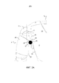
На фиг. 2а и 2b более детально показан плечевой сустав 11 робота 10ʹ. На этих двух фигурах показан предмет 20 круглого сечения, отображающий человеческий палец, который может быть защемлен между туловищем 2 и плечом 3. На обеих фигурах предмет показан в разрезе. На практике предмет 20 может быть стандартным шаблоном, имитирующим человеческий палец. Этот шаблон не должен слишком сильно защемляться между двумя элементами робота. В частности, робот не должен действовать на шаблон усилием, превышающим заданное усилие.In FIG. 2a and 2b, the
На фиг. 2а предмет 20 расположен под плечом 3 на уровне подмышки робота 10ʹ. Плечо 3 стремится опуститься вдоль туловища 2, зажимая предмет подмышкой между плечом 3 и туловищем 2. В примере, представленном на фиг. 2а, нас интересует вращение шарнира 11 вокруг горизонтальной оси 21, перпендикулярной к фронтальной плоскости робота 10ʹ. Фронтальная плоскость расположена параллельно плоскости фиг. 2, и горизонтальная ось 21 перпендикулярна к плоскости фигуры. Шарнир 11 обеспечивает угловое отклонение в заданном диапазоне вокруг оси 21. Плечо 3 может иметь отклонение порядка 180°. Изобретение позволяет ограничить эффект защемления предмета 20, когда плечо 3 приходит к концу хода в конце диапазона, то есть когда плечо 3 расположено вдоль туловища 2. Разумеется, изобретение можно также применять для другого конца диапазона вращения вокруг оси 21, что будет описано ниже со ссылками на фиг. 2b для вращения вокруг другой оси вращения шарнира 11 вокруг вертикальной оси и, в целом, для любого комбинированного движения двух вращений шарнира 11.In FIG. 2a,
Наружная поверхность туловища 2 и плеча 3 образует оболочку, соответственно 22 и 23. В конце хода, когда плечо 3 расположено вдоль туловища 2, оболочка 23 плеча 3 и оболочка 22 туловища 2 по существу входят друг с другом в контакт. В частности, для каждой оболочки существует зона, в которой промежуток между двумя оболочками меньше сечения предмета 20. Эта зона имеет обозначение 25 для оболочки 23 плеча 3 и обозначение 26 для оболочки 22 туловища 2. Согласно изобретению, одна из зон 25,26 или обе зоны 25,26, предназначенные для вхождения друг с другом в контакт, являются гибкими, что обеспечивает их деформацию на заданном расстоянии с усилием, меньшим заданного усилия. Заданным расстоянием является сечение предмета 20. Например, заданное расстояние равно примерно 5 мм, что соответствует диаметру пальца ребенка. Заданное усилие представляет собой максимальное усилие, допустимое во время защемления предмета 20.The outer surface of the
Деформация зоны или зон 25,26 рассматриваемой оболочки происходит в их соответствующей области упругости, чтобы они могли восстанавливать свою первоначальную форму, когда плечо 3 покидает свое положение конца хода относительно туловища 2. В отсутствие предмета 20 между зонами 25 и 26 оболочек 22 и 23 может оставаться небольшой зазор, и может происходить контакт без усилия или даже легкое давление между зонами 25 и 26.The deformation of the zone or zones 25.26 of the shell under consideration occurs in their corresponding elastic region, so that they can restore their original shape when
Наличие этих гибких зон 25 и 26 позволяет роботу больше приблизиться к человеческой морфологии. Гибкие зоны 25 и 26 могут быть выполнены в виде мембран из эластомерного материала, например, на основе силикона или резины.The presence of these
Конец хода шарнира 11 можно зафиксировать путем управления приводом, обеспечивающим движение шарнира 11, или при помощи механического упора, расположенного внутри шарнира 11.The end of the stroke of the
В представленном примере гибкая зона 25 является сплошной внутри ограничивающей ее замкнутой линии 27. Жесткая зона 28 оболочки 23 окружает гибкую зону 25 вдоль всей замкнутой линии 27. Для плеча 3 оболочка в основном является жесткой. На оболочке 23 расположена одна или несколько гибких зон 25. Эти зоны 23 находятся в местах, где плечо 3 может по существу входить в контакт с другим элементом робота 10ʹ, в данном случае с туловищем 2.In the presented example, the
Гибкая зона 26 туловища 2 является прерывистой внутри ограничивающей ее замкнутой линии 30. Плечо 3 проходит через оболочку 22 туловища через разрыв гибкой зоны 26. Жесткая зона 31 оболочки 22 окружает гибкую зону 26 вдоль всей замкнутой линии 30. Иначе говоря, как и в случае плеча 3, оболочка 22 туловища 2 в основной является жесткой. Гибкая зона 26 закреплена на жесткой зоне 31 вдоль замкнутой линии 30. Гибкая зона 26 образует юбку, закрепленную на жесткой зоне 22 и окружающей крепление плеча 3 на туловище 2. Полностью окружая плечо 3, гибкая зона 26 позволяет плечу 3 приближаться к туловищу 2 во всех комбинациях вращения шарнира 11. Кроме того, благодаря своей форме в виде юбки, гибкая зона 26 позволяет ограничить проникновение нежелательных предметов внутрь шарнира 11. Для этого гибкая зона 26 выполнена с возможностью оставаться в контакте с креплением плеча 2 на туловище 2. Гибкая зона 26 может оставаться в контакте либо с шарниром 11, либо с плечом 2. В частности, гибкая зона 26 позволяет предохранить шарнир 11 от окружающей пыли. Гибкая зона 26 позволяет также изолировать возможные дефекты, которые могут возникнуть внутри робота. Например, речь может идти о возгорании, связанном с электрическим дефектом, или о задержании возможных сломанных механических деталей внутри робота.The
На фиг. 2b показано плечо 3, проходящее по существу вертикально вверх. Плечо 3 находится в конце хода своего вращения вокруг оси 21 в конце своего диапазона вращения, противоположному концу, показанному на фиг. 2а. Жесткая зона 28 оболочки 23 плеча 3 слегка вдавливается в гибкую зону 26 оболочки 22 туловища 2. Это вдавливание видно на уровне стрелки 32. На этой фигуре показан предмет 20, защемленный между плечевым суставом и плечом 3. Для ограничения последствий защемления предмета 20 плечо 3 может содержать вторую гибкую зону 25. На уровне туловища 2 предмет 20 вдавливается в гибкую зону 26 туловища 2.In FIG. 2b, a
В целом, туловище 2 и/или плечо 3 имеют необходимое количество гибких зон, находящихся в соответствующих местах, где оболочки этих двух элементов (туловища 2 и плеча 3) могут сближаться или даже соприкасаться во время различных движений плеча 3 относительно туловища 2. Оболочка плеча 3 и туловища 2 на большей части является жесткой. Выполненные в них гибкие зоны 25,26 расположены в продолжении жестких зон, соответственно 28 и 31.In general, the
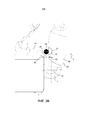
На фиг. 3 показано плечо 3, соединенное с предплечьем 35 робота 10ʹ. Локтевой сустав 36, обеспечивающий подвижность во вращении вокруг оси 37, перпендикулярной к плоскости фиг. 3, соединяет плечо 3 и предплечье 35. На плече 3 находится гибкая зона 26 в виде юбки, через которую проходит локтевой сустав 36. На предплечье 35 гибкая зона 38 продолжает жесткую зону 39 оболочки 40 предплечья 35. Гибкая зона 38 может полностью окружать предплечье 35 и следовать его замкнутой линии. В альтернативном варианте гибкая зона 38 может только частично следовать замкнутой линии, ограничивающей жесткую зону 39. При этом гибкая зона 38 имеет форму кромки, расположенной на уровне, где предплечье 35 ближе всего приближается к плечу 3 во время вращения локтевого сустава 36 в первом направлении вращения. При вращении в направлении, противоположном первому направлению, предплечье 35 располагается по существу на одной линии с плечом 3. Сзади локтевого сустава 36 можно обойтись без гибкой зоны на предплечье 35. Гибкой зоны 26 плеча 3 может быть достаточно, чтобы избегать любого повреждения по причине защемления. Предпочтительно можно предусмотреть, чтобы гибкая зона полностью окружала локтевой сустав 36, даже если локтевой сустав 36 имеет только одну степень свободы во вращении. Часть гибкой зоны 26 не имеет функции защиты от защемления, но сохраняет свои функции защиты от посторонних предметов и изоляции дефектов внутри робота.In FIG. 3 shows the
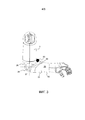
На фиг. 4 более детально показан тазобедренный сустав 13 робота 10ʹ. Тазобедренный сустав 13 может иметь одну или две степени свободы между туловищем 2 и юбкой 7. Можно предусмотреть конфигурацию, сходную с тазобедренным суставом в роботе 10, имеющем две ноги. Например, диапазон углового отклонения тазобедренного сустава 13 меньше 90°. При таком угловом отклонении может быть достаточно гибкой зоны на оболочке одного из элементов робота, соединенного тазобедренным суставом. В представленном примере зона 26 образует нижнюю часть туловища 2. Как и в случае плечевого сустава 11 или локтевого сустава 36 зона 26 в данном случае охватывает туловище 2, делая оборот вокруг его вертикальной оси.In FIG. 4 shows in more detail the
Claims (4)
Applications Claiming Priority (3)
| Application Number | Priority Date | Filing Date | Title |
|---|---|---|---|
| FR1455028A FR3021573B1 (en) | 2014-06-03 | 2014-06-03 | ANTI-BITTING SYSTEM IN A HUMANOID ROBOT |
| FR1455028 | 2014-06-03 | ||
| PCT/EP2015/062459 WO2015185671A1 (en) | 2014-06-03 | 2015-06-03 | Anti-jamming system in a humanoid-type robot |
Publications (3)
| Publication Number | Publication Date |
|---|---|
| RU2016151214A RU2016151214A (en) | 2018-07-09 |
| RU2016151214A3 RU2016151214A3 (en) | 2018-07-09 |
| RU2684026C2 true RU2684026C2 (en) | 2019-04-03 |
Family
ID=51830407
Family Applications (1)
| Application Number | Title | Priority Date | Filing Date |
|---|---|---|---|
| RU2016151214A RU2684026C2 (en) | 2014-06-03 | 2015-06-03 | Anti-jamming system in humanoid-type robot |
Country Status (15)
| Country | Link |
|---|---|
| US (1) | US10137579B2 (en) |
| EP (1) | EP3152013B1 (en) |
| JP (1) | JP6556167B2 (en) |
| KR (1) | KR20170021828A (en) |
| CN (1) | CN106573371B (en) |
| AU (1) | AU2015270477B2 (en) |
| CA (1) | CA2950652C (en) |
| DK (1) | DK3152013T3 (en) |
| ES (1) | ES2692415T3 (en) |
| FR (1) | FR3021573B1 (en) |
| MX (1) | MX2016015823A (en) |
| NZ (1) | NZ726252A (en) |
| RU (1) | RU2684026C2 (en) |
| SG (1) | SG11201609419RA (en) |
| WO (1) | WO2015185671A1 (en) |
Families Citing this family (4)
| Publication number | Priority date | Publication date | Assignee | Title |
|---|---|---|---|---|
| CN107756449B (en) * | 2017-11-10 | 2020-10-02 | 北京康力优蓝机器人科技有限公司 | Anti-pinch detection system for mechanical joint of service robot |
| DE102018202459B3 (en) | 2018-02-19 | 2019-02-21 | Kuka Deutschland Gmbh | Robot arm with at least one deformation element |
| JP7388828B2 (en) * | 2019-05-27 | 2023-11-29 | ファナック株式会社 | robot |
| CN111805554B (en) * | 2020-07-08 | 2023-08-18 | 达闼机器人股份有限公司 | Robot and housing thereof |
Citations (5)
| Publication number | Priority date | Publication date | Assignee | Title |
|---|---|---|---|---|
| JP2000158378A (en) * | 1998-11-26 | 2000-06-13 | Seiko Epson Corp | Robot and robot controller |
| JP2004174644A (en) * | 2002-11-26 | 2004-06-24 | Sony Corp | Control device for leg type mobile robot |
| US20040236469A1 (en) * | 2003-03-23 | 2004-11-25 | Tomohisa Moridaira | Robot apparatus and control method thereof |
| RU2251480C2 (en) * | 2000-11-17 | 2005-05-10 | Хонда Гикен Когё Кабусики Кайся | Walking robot |
| US20110067521A1 (en) * | 2009-09-22 | 2011-03-24 | Gm Global Technology Operations, Inc. | Humanoid robot |
Family Cites Families (4)
| Publication number | Priority date | Publication date | Assignee | Title |
|---|---|---|---|---|
| JP2000317876A (en) * | 1999-05-10 | 2000-11-21 | Sony Corp | Robot apparatus |
| KR100778299B1 (en) | 2001-01-23 | 2007-11-22 | 혼다 기켄 고교 가부시키가이샤 | Multi-finger hand device |
| JP4524435B2 (en) * | 2005-05-11 | 2010-08-18 | 株式会社国際電気通信基礎技術研究所 | Communication robot |
| JP5302647B2 (en) * | 2008-12-09 | 2013-10-02 | 東海ゴム工業株式会社 | Covering material for connecting parts |
-
2014
- 2014-06-03 FR FR1455028A patent/FR3021573B1/en not_active Expired - Fee Related
-
2015
- 2015-06-03 DK DK15727953.0T patent/DK3152013T3/en active
- 2015-06-03 US US15/310,704 patent/US10137579B2/en active Active
- 2015-06-03 ES ES15727953.0T patent/ES2692415T3/en active Active
- 2015-06-03 CA CA2950652A patent/CA2950652C/en not_active Expired - Fee Related
- 2015-06-03 KR KR1020177000012A patent/KR20170021828A/en not_active Application Discontinuation
- 2015-06-03 RU RU2016151214A patent/RU2684026C2/en not_active IP Right Cessation
- 2015-06-03 SG SG11201609419RA patent/SG11201609419RA/en unknown
- 2015-06-03 WO PCT/EP2015/062459 patent/WO2015185671A1/en active Application Filing
- 2015-06-03 NZ NZ726252A patent/NZ726252A/en not_active IP Right Cessation
- 2015-06-03 MX MX2016015823A patent/MX2016015823A/en unknown
- 2015-06-03 EP EP15727953.0A patent/EP3152013B1/en active Active
- 2015-06-03 CN CN201580029765.0A patent/CN106573371B/en active Active
- 2015-06-03 JP JP2016571144A patent/JP6556167B2/en active Active
- 2015-06-03 AU AU2015270477A patent/AU2015270477B2/en not_active Ceased
Patent Citations (5)
| Publication number | Priority date | Publication date | Assignee | Title |
|---|---|---|---|---|
| JP2000158378A (en) * | 1998-11-26 | 2000-06-13 | Seiko Epson Corp | Robot and robot controller |
| RU2251480C2 (en) * | 2000-11-17 | 2005-05-10 | Хонда Гикен Когё Кабусики Кайся | Walking robot |
| JP2004174644A (en) * | 2002-11-26 | 2004-06-24 | Sony Corp | Control device for leg type mobile robot |
| US20040236469A1 (en) * | 2003-03-23 | 2004-11-25 | Tomohisa Moridaira | Robot apparatus and control method thereof |
| US20110067521A1 (en) * | 2009-09-22 | 2011-03-24 | Gm Global Technology Operations, Inc. | Humanoid robot |
Also Published As
| Publication number | Publication date |
|---|---|
| KR20170021828A (en) | 2017-02-28 |
| US20170080582A1 (en) | 2017-03-23 |
| EP3152013B1 (en) | 2018-07-25 |
| WO2015185671A1 (en) | 2015-12-10 |
| DK3152013T3 (en) | 2018-11-19 |
| CN106573371A (en) | 2017-04-19 |
| NZ726252A (en) | 2018-02-23 |
| FR3021573A1 (en) | 2015-12-04 |
| JP2017516672A (en) | 2017-06-22 |
| FR3021573B1 (en) | 2019-04-19 |
| RU2016151214A (en) | 2018-07-09 |
| ES2692415T3 (en) | 2018-12-03 |
| US10137579B2 (en) | 2018-11-27 |
| SG11201609419RA (en) | 2016-12-29 |
| AU2015270477A1 (en) | 2016-12-01 |
| CA2950652A1 (en) | 2015-12-10 |
| RU2016151214A3 (en) | 2018-07-09 |
| CN106573371B (en) | 2019-04-23 |
| AU2015270477B2 (en) | 2017-09-14 |
| EP3152013A1 (en) | 2017-04-12 |
| MX2016015823A (en) | 2017-06-28 |
| CA2950652C (en) | 2020-04-21 |
| JP6556167B2 (en) | 2019-08-07 |
Similar Documents
| Publication | Publication Date | Title |
|---|---|---|
| RU2684026C2 (en) | Anti-jamming system in humanoid-type robot | |
| ITMI20101769A1 (en) | BIOMEDICAL DEVICE FOR ROBOTIZED REHABILITATION OF THE HUMAN UPPER BODY, PARTICULARLY FOR THE NEUROMOTORY REHABILITATION OF THE ARTICULATION OF THE SHOULDER AND OF THE ELBOW. | |
| WO2007113949A1 (en) | Doll toy | |
| WO2013186705A3 (en) | An exoskeleton structure for physical interaction with a human being | |
| US10406699B2 (en) | Secure, motor-driven hinge to be provided on a humanoid robot | |
| KR102406815B1 (en) | Safety protection of robot joints | |
| JP6449337B2 (en) | Safety of humanoid robots | |
| CN103566542A (en) | Device for driving person to carry out gait training by binding feet and shanks | |
| Jung et al. | Kinematic analysis of a 5 DOF upper-limb exoskeleton with a tilted and vertically translating shoulder joint | |
| WO2017077438A1 (en) | Exoskeleton and method of operation thereof | |
| JP6271045B2 (en) | Device for pre-positioning and detachably attaching the articulated limb of a humanoid robot | |
| KR101617820B1 (en) | Wearable 2-DOF Wrist Rehabilitation Robot | |
| CN107756449B (en) | Anti-pinch detection system for mechanical joint of service robot | |
| KR20180050152A (en) | Ankle module for lower limb exoskeleton | |
| Sin et al. | Development of passive upper limb weight-bearing orthosis to enhance voluntary shoulder rotation for activities of daily living | |
| Slavnic et al. | Concept of a mobile robot-assisted gait rehabilitation system—Simulation study | |
| KR102263758B1 (en) | Apparatus for supporting trainee and apparatus for training walk comprising the same | |
| CN112932896A (en) | Control method of axis self-adaptive knee joint rehabilitation robot |
Legal Events
| Date | Code | Title | Description |
|---|---|---|---|
| MM4A | The patent is invalid due to non-payment of fees |
Effective date: 20200604 |