EP3152013B1 - Anti-jamming system in a humanoid-type robot - Google Patents
Anti-jamming system in a humanoid-type robot Download PDFInfo
- Publication number
- EP3152013B1 EP3152013B1 EP15727953.0A EP15727953A EP3152013B1 EP 3152013 B1 EP3152013 B1 EP 3152013B1 EP 15727953 A EP15727953 A EP 15727953A EP 3152013 B1 EP3152013 B1 EP 3152013B1
- Authority
- EP
- European Patent Office
- Prior art keywords
- robot
- arm
- zone
- elements
- trunk
- Prior art date
- Legal status (The legal status is an assumption and is not a legal conclusion. Google has not performed a legal analysis and makes no representation as to the accuracy of the status listed.)
- Active
Links
Images


Classifications
-
- B—PERFORMING OPERATIONS; TRANSPORTING
- B25—HAND TOOLS; PORTABLE POWER-DRIVEN TOOLS; MANIPULATORS
- B25J—MANIPULATORS; CHAMBERS PROVIDED WITH MANIPULATION DEVICES
- B25J9/00—Programme-controlled manipulators
- B25J9/0009—Constructional details, e.g. manipulator supports, bases
-
- B—PERFORMING OPERATIONS; TRANSPORTING
- B25—HAND TOOLS; PORTABLE POWER-DRIVEN TOOLS; MANIPULATORS
- B25J—MANIPULATORS; CHAMBERS PROVIDED WITH MANIPULATION DEVICES
- B25J19/00—Accessories fitted to manipulators, e.g. for monitoring, for viewing; Safety devices combined with or specially adapted for use in connection with manipulators
- B25J19/0091—Shock absorbers
-
- B—PERFORMING OPERATIONS; TRANSPORTING
- B25—HAND TOOLS; PORTABLE POWER-DRIVEN TOOLS; MANIPULATORS
- B25J—MANIPULATORS; CHAMBERS PROVIDED WITH MANIPULATION DEVICES
- B25J17/00—Joints
-
- B—PERFORMING OPERATIONS; TRANSPORTING
- B25—HAND TOOLS; PORTABLE POWER-DRIVEN TOOLS; MANIPULATORS
- B25J—MANIPULATORS; CHAMBERS PROVIDED WITH MANIPULATION DEVICES
- B25J19/00—Accessories fitted to manipulators, e.g. for monitoring, for viewing; Safety devices combined with or specially adapted for use in connection with manipulators
- B25J19/0075—Means for protecting the manipulator from its environment or vice versa
-
- B—PERFORMING OPERATIONS; TRANSPORTING
- B25—HAND TOOLS; PORTABLE POWER-DRIVEN TOOLS; MANIPULATORS
- B25J—MANIPULATORS; CHAMBERS PROVIDED WITH MANIPULATION DEVICES
- B25J19/00—Accessories fitted to manipulators, e.g. for monitoring, for viewing; Safety devices combined with or specially adapted for use in connection with manipulators
- B25J19/06—Safety devices
Definitions
- the invention relates to the safe use of a humanoid robot.
- a robot can be called a humanoid from the moment it has certain attributes of the appearance and functionality of the man such as for example a head, a trunk, two arms, two hands, two legs or two feet. Some robots with only the upper body can also be considered as having humanoid characters. Humanoid robots are able to walk or move on a platform with wheels, to make gestures, with the limbs or with the head. The complexity of the gestures they are able to perform increases constantly.
- the subject of the invention is a robot with a humanoid character comprising two elements and an articulation with at least one degree of freedom connecting the two elements, the two elements each comprising a skin delimiting their external surface, the articulation allowing a deflection in a given range, a first of the two elements being intended to come substantially in contact with an area of the skin of a second of the two elements at one end of the range.
- the zone is flexible so as to allow its deformation of a given distance with a force less than a given effort and the first element is hooked to the second element through the flexible zone.
- the skins of the two elements are for the most part rigid and advantageously, at least one flexible zone is arranged in the continuity of a rigid zone of the skin.
- the flexible zone is discontinuous within a closed line.
- the first element passes through the skin by the discontinuity of the flexible zone and a rigid zone of the skin surrounds the flexible zone all along the closed line.
- the robot with humanoid characters 10 also includes several joints to move the legs of the robot and reproduce the movement of walking, especially hip-like joints, between the trunk and each of the thighs, at one knee, between a thigh and the leg, and an ankle between the leg and the foot.
- joints to move the legs of the robot and reproduce the movement of walking especially hip-like joints, between the trunk and each of the thighs, at one knee, between a thigh and the leg, and an ankle between the leg and the foot.
- Several forms of motorized joints are implemented, causing one of the members to move in one or more degrees of freedom in rotation.
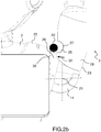
- FIGS. 2a and 2b represent in more detail the shoulder 11 of the robot 10 '.
- a circular section object 20 representing a human finger may be pinched between the trunk 2 and the arm 3.
- the object 20 is shown in section in both figures.
- the object 20 may be a normalized template representing a human finger. This caliber must not be pinched too strongly between two elements of the robot. More precisely, the robot must not exert on the caliber a greater effort than a given effort.
- the presence of these flexible zones 25 and 26 allows the robot to approach the human morphology.
- the soft areas 25 and 26 of the skin may be formed from membranes made of an elastomeric material such as for example silicone or rubber.
- the end of travel of the hinge 11 can be achieved by controlling an actuator allowing the movement of the hinge 11 or by a mechanical stop disposed inside the hinge 11.
- the flexible zone 25 is continuous inside a closed line 27 which limits it.
- a rigid zone 28 of the skin 23 surrounds the flexible zone 25 all along the closed line 27.
- the skin 23 is mainly rigid.
- One or more flexible zones 25 are disposed on the skin 23. These zones 23 are located in places where the arm 3 is likely to come into contact with another element of the robot 10 ', the trunk 2 in this case.
- the flexible zone 26 of the trunk 2 is discontinuous within a closed line 30 which limits it.
- the arm 3 passes through the skin 22 of the trunk by the discontinuity of the flexible zone 26.
- a rigid zone 31 of the skin 22 surrounds the flexible zone 26 all along the closed line 30.
- the skin 22 of the trunk 2 is , as for the arm 3, mainly rigid.
- the flexible zone 26 is fixed to the rigid zone 31 along the closed line 30.
- the flexible zone 26 forms a skirt fixed to the rigid zone 22 and surrounding the attachment of the arm 3 on the trunk 2. By completely surrounding the arm 3, the flexible zone 26 allows the arm 3 to approach the trunk 2 in all the rotation combinations of the hinge 11. Moreover, thanks to its skirt shape, the flexible zone 26 makes it possible to limit the penetration of objects undesirable inside the hinge 11.
- the flexible zone 26 is configured to remain in contact with the attachment of the arm 3 on the trunk 2.
- the flexible zone 26 can remain in contact with the articulation 11, or with the arm 3.
- the flexible zone 26 allows in particular to protect the hinge 11 ambient dust.
- the flexible zone 26 also makes it possible to confine any defects that may occur inside the robot. It may for example be the start of fire related to an electrical fault and keep inside the robot any broken mechanical parts.
- the trunk 2 and / or the arm 3 have as many soft areas as necessary located where the skins of these two elements (trunk 2 and arm 3) can approach or even collide during the different movements arm 3 with respect to the trunk 2.
- the arm 3 and trunk 2 skin is mostly rigid.
- the flexible zone or zones 25, 26 which are made there are arranged in the continuity of the rigid zones, respectively 28 and 31.
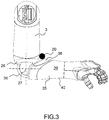
- the figure 3 represents the arm 3 connected to a forearm 35 of the robot 10 '.
- a bend 36 providing mobility in rotation about an axis 37 perpendicular to the plane of the figure 3 connects the arm 3 and the forearm 35.
- the flexible zone 38 can completely surround the forearm 35 and follow a closed line thereof. Alternatively, the flexible zone 38 may follow only partially the closed line limiting the rigid zone 39.
- the flexible zone 38 is then in the form of a lip disposed at the level where the forearm 35 is closest to the arm 3 when the rotation of the elbow 36 in a first direction of rotation.
- the forearm 35 In a rotation in opposite direction to the first direction, the forearm 35 is substantially in alignment with the arm 3. On the rear of the elbow 36, there is no need for a flexible zone on the forearm 35.
- the flexible zone 26 of the arm 3 may be sufficient to prevent damage from pinching. It is advantageous to provide that the flexible zone completely surrounds the elbow 36, even if the elbow 36 has only one degree of freedom in rotation. Part of the flexible zone 26 has no anti-jamming function but retains its functions of protection against foreign objects and containment of defects inside the robot.
- the figure 4 represents in more detail the hip 13 of the robot 10 '.
- the hip 13 may have one or two degrees of freedom between the trunk 2 and the skirt 7.
- the range of angular deflection of the hip 13 is for example less than 90 °.
- a flexible area on the skin of one of the elements of the robot connected by the hip can suffice.
- an area 26 forms the lower part of the trunk 2.
- the zone 26 here is around the trunk 2 about its vertical axis.
Description
L'invention concerne la sécurité d'utilisation d'un robot à caractère humanoïde.The invention relates to the safe use of a humanoid robot.
Un robot peut être qualifié d'humanoïde à partir du moment où il possède certains attributs de l'apparence et des fonctionnalités de l'homme comme par exemple une tête, un tronc, deux bras, deux mains, deux jambes ou deux pieds. Certains robots ne possédant que le haut du corps peuvent également être considérés comme possédant des caractères humanoïdes. Des robots humanoïdes sont capables de marcher ou de se déplacer sur une plateforme munie de roues, de faire des gestes, avec les membres ou avec la tête. La complexité des gestes qu'ils sont capables d'effectuer augmente sans cesse.A robot can be called a humanoid from the moment it has certain attributes of the appearance and functionality of the man such as for example a head, a trunk, two arms, two hands, two legs or two feet. Some robots with only the upper body can also be considered as having humanoid characters. Humanoid robots are able to walk or move on a platform with wheels, to make gestures, with the limbs or with the head. The complexity of the gestures they are able to perform increases constantly.
Ces robots sont destinés à interagir avec des humains et il est nécessaire d'éviter que les gestes des robots ne puissent blesser les humains qui les entourent. Plus précisément, lors du mouvement de certaines articulations du robot, celui-ci pourrait pincer des doigts humains se trouvant à proximité. Par exemple lorsque le bras d'un robot se rapproche de son tronc, il y a risque de coincement entre le bras et le tronc. De façon plus générale, le risque de coincement existe entre deux éléments du robot, articulés entre eux.These robots are intended to interact with humans and it is necessary to avoid that the actions of robots can not hurt the humans around them. Specifically, when moving certain joints of the robot, it could pinch human fingers nearby. For example, when the arm of a robot is approaching its trunk, there is a risk of jamming between the arm and the trunk. More generally, the risk of jamming exists between two elements of the robot, articulated between them.
Plusieurs solutions ont été imaginées pour réduire le risque de coincement ou pour en limiter les conséquences. Pour éviter tout coincement, on peut limiter le débattement d'une articulation au moyen de butée permettant de conserver un écart suffisant entre les éléments reliés par l'articulation considérée. Cette solution limite les possibilités du robot en lui interdisant certains mouvements. L'anthropomorphisme du robot est alors dégradé.Several solutions have been devised to reduce the risk of jamming or to limit the consequences. To avoid any jamming, it is possible to limit the deflection of a joint by means of an abutment making it possible to maintain a sufficient distance between the elements connected by the joint considered. This solution limits the possibilities of the robot by prohibiting certain movements. The anthropomorphism of the robot is then degraded.
Pour limiter les conséquences d'un coincement, on peut réduire l'effort produit par l'actionneur mouvant l'articulation considérée. Cette réduction d'effort limite aussi les possibilités du robot qui, par exemple, ne pourra plus soulever des charges importantes. Il est possible de limiter l'effort d'un actionneur uniquement en fin de course, lorsque les deux éléments se rapprochent. Cette limitation nécessite un pilotage complexe de l'actionneur. Ce pilotage est couteux à mettre en oeuvre et peut être source d'une réduction de fiabilité du robot.To limit the consequences of jamming, it can reduce the force produced by the actuator moving the joint considered. This reduction of effort also limits the possibilities of the robot, which, for example, will no longer be able to lift heavy loads. It is possible to limit the effort of an actuator only at the end of the stroke, when the two elements come closer together. This limitation requires complex control of the actuator. This control is expensive to implement and can be a source of a reduction of reliability of the robot.
Le document
L'invention vise à améliorer encore la sécurité de fonctionnement d'un robot au moyen d'une solution complètement passive permettant de limiter l'effort de pincement en fin de course d'un débattement d'une articulation.The invention aims to further improve the operational safety of a robot by means of a completely passive solution for limiting the clamping force at the end of the stroke of a deflection of a joint.
A cet effet, l'invention a pour objet un robot à caractère humanoïde comprenant deux éléments et une articulation à au moins un degré de liberté reliant les deux éléments, les deux éléments comprenant chacun une peau délimitant leur surface externe, l'articulation permettant un débattement dans une plage donnée, un premier des deux éléments étant destiné à venir sensiblement au contact d'une zone de la peau d'un second des deux éléments à une extrémité de la plage. La zone est souple de façon à permettre sa déformation d'une distance donnée avec un effort inférieur à un effort donné et le premier élément est accroché au second élément en traversant la zone souple.For this purpose, the subject of the invention is a robot with a humanoid character comprising two elements and an articulation with at least one degree of freedom connecting the two elements, the two elements each comprising a skin delimiting their external surface, the articulation allowing a deflection in a given range, a first of the two elements being intended to come substantially in contact with an area of the skin of a second of the two elements at one end of the range. The zone is flexible so as to allow its deformation of a given distance with a force less than a given effort and the first element is hooked to the second element through the flexible zone.
La zone souple peut être configurée pour rester en contact soit avec l'articulation, soit avec le premier élément.The flexible zone may be configured to remain in contact with either the joint or the first element.
Le robot peut comprendre une butée appartenant à l'un des deux éléments. A l'extrémité de la plage, l'autre des deux éléments vient au contact de la butée.The robot may comprise a stop belonging to one of the two elements. At the end of the beach, the other of the two elements comes into contact with the stop.
Les peaux des deux éléments sont en majeure partie rigide et avantageusement, au moins une zone souple est disposée dans la continuité d'une zone rigide de la peau.The skins of the two elements are for the most part rigid and advantageously, at least one flexible zone is arranged in the continuity of a rigid zone of the skin.
La zone souple est discontinue à l'intérieur d'une ligne fermée. Le premier élément traverse la peau par la discontinuité de la zone souple et une zone rigide de la peau entoure la zone souple tout au long de la ligne fermée.The flexible zone is discontinuous within a closed line. The first element passes through the skin by the discontinuity of the flexible zone and a rigid zone of the skin surrounds the flexible zone all along the closed line.
L'invention sera mieux comprise et d'autres avantages apparaîtront à la lecture de la description détaillée d'un mode de réalisation donné à titre d'exemple, description illustrée par le dessin joint dans lequel :
- les
figures 1a et 1b représentent deux exemples de robots mettant en oeuvre l'invention ; - les
figures 2a et2b représentent une épaule du robot de lafigure 1b ; - la
figure 3 représente un bras du robot de lafigure 1b ; - la
figure 4 représente une hanche du robot de lafigure 1b .
- the
Figures 1a and 1b represent two examples of robots implementing the invention; - the
Figures 2a and2b represent a robot shoulder of thefigure 1b ; - the
figure 3 represents a robot arm of thefigure 1b ; - the
figure 4 represents a hip of the robot of thefigure 1b .
Par souci de clarté, les mêmes éléments porteront les mêmes repères dans les différentes figures.For the sake of clarity, the same elements will bear the same references in the different figures.
Les
Le robot à caractères humanoïdes 10 comprend également plusieurs articulations pour mettre en mouvement les jambes du robot et reproduire le mouvement de la marche, en particulier des articulations assimilables à une hanche, entre le tronc et chacune des cuisses, à un genou, entre une cuisse et la jambe, et à une cheville entre la jambe et le pied. Plusieurs formes d'articulations motorisées sont mises en oeuvre, entrainant en mouvement l'un des membres selon un ou plusieurs degrés de liberté en rotation.The robot with
Le robot à caractères humanoïdes 10' présente une architecture différente. Pour améliorer la stabilité et abaisser le centre de gravité du robot, le robot ne comprend pas de jambe mais une jupe 7 comprenant en sa base un tripode 14 capable de déplacer le robot. La jupe 7 comprend aussi une première articulation 12 s'apparentant à un genou, entre une jambe 7a et une cuisse 7b. Une deuxième articulation 13 s'apparentant à une hanche est relie le tronc 2 et la cuisse 7b. Ces deux articulations 12 et 13 sont des liaisons pivots motorisées autour d'un axe de rotation. L'axe de rotation Xa de l'articulation 12 et l'axe de rotation Xb de l'articulation 13 sont sensiblement parallèles à un axe reliant les deux épaules du robot, permettant d'incliner le robot vers l'avant ou vers l'arrière.The robot with humanoid characters 10 'has a different architecture. To improve stability and lower the robot's center of gravity, the robot does not include a leg but a
Les
Sur la
La surface externe du tronc 2 et du bras 3 forme une peau, respectivement 22 et 23. En bout de course, lorsque le bras 3 s'étend le long du tronc 2, la peau 23 du bras 3 et la peau 22 du tronc 2 viennent sensiblement au contact l'une de l'autre. Plus précisément, il existe pour chaque peau, une zone où l'écart entre les deux peaux est inférieur à la section de l'objet 20. Cette zone porte le repère 25 pour la peau 23 du bras 3 et le repère 26 pour la peau 22 du tronc 2. Selon l'invention, une des zones 25, 26 ou les deux zones 25, 26, destinées à venir au contact, sont souples de façon à permettre leur déformation d'une distance donnée avec un effort inférieur à un effort donné. La distance donnée est la section de l'objet 20. La distance donnée est par exemple de l'ordre de 5mm, représentant le diamètre du doigt d'un enfant. L'effort donné représente l'effort maximal que l'on peut autoriser lors du pincement de l'objet 20.The outer surface of the
La déformation de la zone ou des zones 25, 26, de la peau considérée se fait dans leur domaine élastique respectif de façon à reprendre leur forme initiale lorsque le bras 3 quitte sa position fin de course par rapport au tronc 2. En l'absence de l'objet 20, on peut avoir un léger écart entre les zones 25 et 26 des peaux 22 et 23, un contact sans effort ou même une légère pression entre les zones 25 et 26.The deformation of the zone or
La présence de ces zones souples 25 et 26 permet au robot de se rapprocher de la morphologie humaine. Les zones souples 25 et 26 de la peau peuvent être formées à partir de membranes réalisées dans un matériau élastomère comme par exemple à base de silicone ou de caoutchouc.The presence of these
La fin de course de l'articulation 11 peut être réalisée par un pilotage d'un actionneur permettant le mouvement de l'articulation 11 ou par une butée mécanique disposée à l'intérieur de l'articulation 11.The end of travel of the
Dans l'exemple représenté, la zone souple 25 est continue à l'intérieur d'une ligne fermée 27 qui la limite. Une zone rigide 28 de la peau 23 entoure la zone souple 25 tout au long de la ligne fermée 27. Pour le bras, 3, la peau 23 est principalement rigide. Une ou plusieurs zones souples 25 sont disposées sur la peau 23. Ces zones 23 sont localisées à des endroits où le bras 3 est susceptible de venir sensiblement au contact d'un autre élément du robot 10', le tronc 2 en l'occurrence.In the example shown, the
La zone souple 26 du tronc 2 est discontinue à l'intérieur d'une ligne fermée 30 qui la limite. Le bras 3 traverse la peau 22 du tronc par la discontinuité de la zone souple 26. Une zone rigide 31 de la peau 22 entoure la zone souple 26 tout au long de la ligne fermée 30. Autrement dit, la peau 22 du tronc 2 est, comme pour le bras 3, principalement rigide. La zone souple 26 est fixée à la zone rigide 31 le long de la ligne fermée 30. La zone souple 26 forme une jupe fixée à la zone rigide 22 et entourant l'accrochage du bras 3 sur le tronc 2. En entourant complètement le bras 3, la zone souple 26 permet au bras 3 de se rapprocher du tronc 2 dans toutes les combinaisons de rotation de l'articulation 11. De plus, grâce à sa forme de jupe, la zone souple 26 permet de limiter la pénétration d'objets indésirables à l'intérieur de l'articulation 11. A cet effet, la zone souple 26 est configurée pour rester en contact avec l'accrochage du bras 3 sur le tronc 2. La zone souple 26 peut rester en contact soit avec l'articulation 11, soit avec le bras 3. La zone souple 26 permet notamment de protéger l'articulation 11 des poussières ambiantes. La zone souple 26 permet également de confiner d'éventuels défauts pouvant intervenir à l'intérieur du robot. Il peut par exemple s'agir de départ de feu liés à un défaut électrique et de conserver à l'intérieur du robot d'éventuelles pièces mécaniques cassées.The
La
De façon plus générale, le tronc 2 et/ou le bras 3 possèdent autant de zones souples que nécessaire situées aux endroits ou les peaux de ces deux éléments (tronc 2 et bras 3) peuvent se rapprocher ou même entrer en collision lors des différents mouvements du bras 3 par rapport au tronc 2. La peau du bras 3 et du tronc 2 est en majeure partie rigide. La ou les zones souples 25, 26 qui y sont réalisées sont disposées dans la continuité des zones rigides, respectivement 28 et 31.More generally, the
La
La
Claims (4)
- A humanoid-type robot comprising two elements (2, 3) and an articulation (11) with at least one degree of freedom linking the two elements, the two elements each comprising a skin (22, 23) delimiting their outer surface, the articulation (11) allowing a travel within a given range, a first of the two elements (2, 3) being intended to come substantially into contact with a zone (26) of the skin (22, 23) of a second of the two elements at an end of the range, the zone (26) being flexible so as to allow the deformation thereof by a given distance with a force less than a given force, characterized in that the first element (3) is attached to the second element (2) by passing through the flexible zone (26).
- The robot as claimed in claim 1, characterized in that the flexible zone (26) is configured to remain in contact either with the articulation (11), or with the first element (3).
- The robot as claimed in one of the preceding claims, characterized in that it comprises an abutment belonging to one of the two elements (2, 3), and in that at the end of the range, the other of the two elements (2, 3) comes into contact with the abutment.
- The robot as claimed in one of the preceding claims, characterized in that the skins (22, 23) of the two elements (2, 3) are mostly rigid and in that at least one flexible zone (26) is arranged in the continuity of a rigid zone (28, 31) of the skin (22, 23).
Applications Claiming Priority (2)
| Application Number | Priority Date | Filing Date | Title |
|---|---|---|---|
| FR1455028A FR3021573B1 (en) | 2014-06-03 | 2014-06-03 | ANTI-BITTING SYSTEM IN A HUMANOID ROBOT |
| PCT/EP2015/062459 WO2015185671A1 (en) | 2014-06-03 | 2015-06-03 | Anti-jamming system in a humanoid-type robot |
Publications (2)
| Publication Number | Publication Date |
|---|---|
| EP3152013A1 EP3152013A1 (en) | 2017-04-12 |
| EP3152013B1 true EP3152013B1 (en) | 2018-07-25 |
Family
ID=51830407
Family Applications (1)
| Application Number | Title | Priority Date | Filing Date |
|---|---|---|---|
| EP15727953.0A Active EP3152013B1 (en) | 2014-06-03 | 2015-06-03 | Anti-jamming system in a humanoid-type robot |
Country Status (15)
| Country | Link |
|---|---|
| US (1) | US10137579B2 (en) |
| EP (1) | EP3152013B1 (en) |
| JP (1) | JP6556167B2 (en) |
| KR (1) | KR20170021828A (en) |
| CN (1) | CN106573371B (en) |
| AU (1) | AU2015270477B2 (en) |
| CA (1) | CA2950652C (en) |
| DK (1) | DK3152013T3 (en) |
| ES (1) | ES2692415T3 (en) |
| FR (1) | FR3021573B1 (en) |
| MX (1) | MX2016015823A (en) |
| NZ (1) | NZ726252A (en) |
| RU (1) | RU2684026C2 (en) |
| SG (1) | SG11201609419RA (en) |
| WO (1) | WO2015185671A1 (en) |
Families Citing this family (4)
| Publication number | Priority date | Publication date | Assignee | Title |
|---|---|---|---|---|
| CN107756449B (en) * | 2017-11-10 | 2020-10-02 | 北京康力优蓝机器人科技有限公司 | Anti-pinch detection system for mechanical joint of service robot |
| DE102018202459B3 (en) | 2018-02-19 | 2019-02-21 | Kuka Deutschland Gmbh | Robot arm with at least one deformation element |
| JP7388828B2 (en) * | 2019-05-27 | 2023-11-29 | ファナック株式会社 | robot |
| CN111805554B (en) * | 2020-07-08 | 2023-08-18 | 达闼机器人股份有限公司 | Robot and housing thereof |
Family Cites Families (9)
| Publication number | Priority date | Publication date | Assignee | Title |
|---|---|---|---|---|
| JP2000158378A (en) * | 1998-11-26 | 2000-06-13 | Seiko Epson Corp | Robot and robot controller |
| JP2000317876A (en) * | 1999-05-10 | 2000-11-21 | Sony Corp | Robot apparatus |
| DE60137650D1 (en) | 2000-11-17 | 2009-03-26 | Honda Motor Co Ltd | ROBOT WITH LEGS |
| WO2002058896A1 (en) * | 2001-01-23 | 2002-08-01 | Honda Giken Kogyo Kabushiki Kaisha | Multi-finger hand device |
| JP4155804B2 (en) * | 2002-11-26 | 2008-09-24 | ソニー株式会社 | Control device for legged mobile robot |
| US7761184B2 (en) * | 2003-03-23 | 2010-07-20 | Sony Corporation | Robot apparatus and control method thereof |
| JP4524435B2 (en) * | 2005-05-11 | 2010-08-18 | 株式会社国際電気通信基礎技術研究所 | Communication robot |
| JP5302647B2 (en) | 2008-12-09 | 2013-10-02 | 東海ゴム工業株式会社 | Covering material for connecting parts |
| US8511964B2 (en) * | 2009-09-22 | 2013-08-20 | GM Global Technology Operations LLC | Humanoid robot |
-
2014
- 2014-06-03 FR FR1455028A patent/FR3021573B1/en not_active Expired - Fee Related
-
2015
- 2015-06-03 SG SG11201609419RA patent/SG11201609419RA/en unknown
- 2015-06-03 DK DK15727953.0T patent/DK3152013T3/en active
- 2015-06-03 RU RU2016151214A patent/RU2684026C2/en not_active IP Right Cessation
- 2015-06-03 CN CN201580029765.0A patent/CN106573371B/en active Active
- 2015-06-03 AU AU2015270477A patent/AU2015270477B2/en not_active Ceased
- 2015-06-03 US US15/310,704 patent/US10137579B2/en active Active
- 2015-06-03 JP JP2016571144A patent/JP6556167B2/en active Active
- 2015-06-03 EP EP15727953.0A patent/EP3152013B1/en active Active
- 2015-06-03 CA CA2950652A patent/CA2950652C/en not_active Expired - Fee Related
- 2015-06-03 NZ NZ726252A patent/NZ726252A/en not_active IP Right Cessation
- 2015-06-03 ES ES15727953.0T patent/ES2692415T3/en active Active
- 2015-06-03 MX MX2016015823A patent/MX2016015823A/en unknown
- 2015-06-03 WO PCT/EP2015/062459 patent/WO2015185671A1/en active Application Filing
- 2015-06-03 KR KR1020177000012A patent/KR20170021828A/en not_active Application Discontinuation
Non-Patent Citations (1)
| Title |
|---|
| None * |
Also Published As
| Publication number | Publication date |
|---|---|
| RU2016151214A3 (en) | 2018-07-09 |
| CA2950652C (en) | 2020-04-21 |
| MX2016015823A (en) | 2017-06-28 |
| DK3152013T3 (en) | 2018-11-19 |
| NZ726252A (en) | 2018-02-23 |
| US20170080582A1 (en) | 2017-03-23 |
| RU2684026C2 (en) | 2019-04-03 |
| FR3021573B1 (en) | 2019-04-19 |
| JP2017516672A (en) | 2017-06-22 |
| FR3021573A1 (en) | 2015-12-04 |
| SG11201609419RA (en) | 2016-12-29 |
| EP3152013A1 (en) | 2017-04-12 |
| CA2950652A1 (en) | 2015-12-10 |
| US10137579B2 (en) | 2018-11-27 |
| CN106573371B (en) | 2019-04-23 |
| RU2016151214A (en) | 2018-07-09 |
| KR20170021828A (en) | 2017-02-28 |
| ES2692415T3 (en) | 2018-12-03 |
| WO2015185671A1 (en) | 2015-12-10 |
| CN106573371A (en) | 2017-04-19 |
| AU2015270477B2 (en) | 2017-09-14 |
| AU2015270477A1 (en) | 2016-12-01 |
| JP6556167B2 (en) | 2019-08-07 |
Similar Documents
| Publication | Publication Date | Title |
|---|---|---|
| EP3152013B1 (en) | Anti-jamming system in a humanoid-type robot | |
| EP0596797B1 (en) | Foot of a walking robot | |
| EP3102369B1 (en) | Hand intended for being provided on a humanoid robot with improved fingers | |
| EP3148920B1 (en) | Tool for raising a vehicle | |
| FR2949669A1 (en) | SHOULDER MECHANISM FOR ORTHESIS | |
| EP3595593B1 (en) | Foot prosthesis comprising a damping member | |
| EP3732004B1 (en) | Safety protection of a robot joint | |
| WO2016162414A1 (en) | Exoskeleton including connected shells with passive degrees of mobility | |
| FR3027514B1 (en) | DEAMBULATION APPARATUS | |
| WO2017085014A1 (en) | Motorized humanoid robot | |
| EP3152008A1 (en) | Safety of a humanoid-type robot | |
| FR3036613A1 (en) | LOWER MEMBER JOINT FOR BIPEDE LOCOMOTION | |
| FR2664493A1 (en) | ARTICULATION FOR ORTHESIS OF LOCKABLE LOWER MEMBERS IN THE EXTENSION POSITION OF THESE MEMBERS. | |
| FR3080762A1 (en) | DEVICE FOR JOINT | |
| WO2015124711A1 (en) | Robot arm joint, particularly for haptic and/or cobotic uses | |
| FR3023707B1 (en) | SET INTENDED TO BE PLACED ON A MEMBER OF A PERSON, INCLUDING AN ARTICULATION DEVICE AND MEANS OF LIMITING THE ANGLE OF THE ARTICULATION | |
| CH707939B1 (en) | Glasses with two folding legs. | |
| FR2991148A1 (en) | Device for fixing of eyeglasses or sunglasses to chest pocket of clothing, has clamp presenting reception notch for reception of hinge of pair of glasses so as to retain glasses by fitment and pinching | |
| FR2983701A1 (en) | Safety device i.e. ear stopper, for protection of individual against noise pollutions, has housing connected to proximal end of tube, where closing unit of housing is movable between opening position and closing position of housing | |
| EP3181000A1 (en) | Motorcycle helmet comprising a reversible lip seal and a raisable chinguard | |
| FR3032623A1 (en) | MANNEQUIN FOR DANCE EXERCISE |
Legal Events
| Date | Code | Title | Description |
|---|---|---|---|
| STAA | Information on the status of an ep patent application or granted ep patent |
Free format text: STATUS: THE INTERNATIONAL PUBLICATION HAS BEEN MADE |
|
| PUAI | Public reference made under article 153(3) epc to a published international application that has entered the european phase |
Free format text: ORIGINAL CODE: 0009012 |
|
| STAA | Information on the status of an ep patent application or granted ep patent |
Free format text: STATUS: REQUEST FOR EXAMINATION WAS MADE |
|
| 17P | Request for examination filed |
Effective date: 20161227 |
|
| AK | Designated contracting states |
Kind code of ref document: A1 Designated state(s): AL AT BE BG CH CY CZ DE DK EE ES FI FR GB GR HR HU IE IS IT LI LT LU LV MC MK MT NL NO PL PT RO RS SE SI SK SM TR |
|
| AX | Request for extension of the european patent |
Extension state: BA ME |
|
| DAV | Request for validation of the european patent (deleted) | ||
| DAX | Request for extension of the european patent (deleted) | ||
| GRAP | Despatch of communication of intention to grant a patent |
Free format text: ORIGINAL CODE: EPIDOSNIGR1 |
|
| STAA | Information on the status of an ep patent application or granted ep patent |
Free format text: STATUS: GRANT OF PATENT IS INTENDED |
|
| INTG | Intention to grant announced |
Effective date: 20180118 |
|
| GRAS | Grant fee paid |
Free format text: ORIGINAL CODE: EPIDOSNIGR3 |
|
| GRAJ | Information related to disapproval of communication of intention to grant by the applicant or resumption of examination proceedings by the epo deleted |
Free format text: ORIGINAL CODE: EPIDOSDIGR1 |
|
| GRAL | Information related to payment of fee for publishing/printing deleted |
Free format text: ORIGINAL CODE: EPIDOSDIGR3 |
|
| STAA | Information on the status of an ep patent application or granted ep patent |
Free format text: STATUS: REQUEST FOR EXAMINATION WAS MADE |
|
| GRAR | Information related to intention to grant a patent recorded |
Free format text: ORIGINAL CODE: EPIDOSNIGR71 |
|
| STAA | Information on the status of an ep patent application or granted ep patent |
Free format text: STATUS: GRANT OF PATENT IS INTENDED |
|
| GRAA | (expected) grant |
Free format text: ORIGINAL CODE: 0009210 |
|
| STAA | Information on the status of an ep patent application or granted ep patent |
Free format text: STATUS: THE PATENT HAS BEEN GRANTED |
|
| INTC | Intention to grant announced (deleted) | ||
| AK | Designated contracting states |
Kind code of ref document: B1 Designated state(s): AL AT BE BG CH CY CZ DE DK EE ES FI FR GB GR HR HU IE IS IT LI LT LU LV MC MK MT NL NO PL PT RO RS SE SI SK SM TR |
|
| INTG | Intention to grant announced |
Effective date: 20180619 |
|
| REG | Reference to a national code |
Ref country code: GB Ref legal event code: FG4D Free format text: NOT ENGLISH |
|
| REG | Reference to a national code |
Ref country code: CH Ref legal event code: EP |
|
| REG | Reference to a national code |
Ref country code: AT Ref legal event code: REF Ref document number: 1021252 Country of ref document: AT Kind code of ref document: T Effective date: 20180815 |
|
| REG | Reference to a national code |
Ref country code: IE Ref legal event code: FG4D Free format text: LANGUAGE OF EP DOCUMENT: FRENCH |
|
| REG | Reference to a national code |
Ref country code: DE Ref legal event code: R096 Ref document number: 602015014025 Country of ref document: DE |
|
| REG | Reference to a national code |
Ref country code: CH Ref legal event code: NV Representative=s name: SERVOPATENT GMBH, CH |
|
| REG | Reference to a national code |
Ref country code: NL Ref legal event code: FP |
|
| REG | Reference to a national code |
Ref country code: SE Ref legal event code: TRGR |
|
| REG | Reference to a national code |
Ref country code: DK Ref legal event code: T3 Effective date: 20181112 |
|
| REG | Reference to a national code |
Ref country code: ES Ref legal event code: FG2A Ref document number: 2692415 Country of ref document: ES Kind code of ref document: T3 Effective date: 20181203 |
|
| REG | Reference to a national code |
Ref country code: LT Ref legal event code: MG4D |
|
| REG | Reference to a national code |
Ref country code: NO Ref legal event code: T2 Effective date: 20180725 |
|
| REG | Reference to a national code |
Ref country code: AT Ref legal event code: MK05 Ref document number: 1021252 Country of ref document: AT Kind code of ref document: T Effective date: 20180725 |
|
| PG25 | Lapsed in a contracting state [announced via postgrant information from national office to epo] |
Ref country code: LT Free format text: LAPSE BECAUSE OF FAILURE TO SUBMIT A TRANSLATION OF THE DESCRIPTION OR TO PAY THE FEE WITHIN THE PRESCRIBED TIME-LIMIT Effective date: 20180725 Ref country code: PL Free format text: LAPSE BECAUSE OF FAILURE TO SUBMIT A TRANSLATION OF THE DESCRIPTION OR TO PAY THE FEE WITHIN THE PRESCRIBED TIME-LIMIT Effective date: 20180725 Ref country code: IS Free format text: LAPSE BECAUSE OF FAILURE TO SUBMIT A TRANSLATION OF THE DESCRIPTION OR TO PAY THE FEE WITHIN THE PRESCRIBED TIME-LIMIT Effective date: 20181125 Ref country code: BG Free format text: LAPSE BECAUSE OF FAILURE TO SUBMIT A TRANSLATION OF THE DESCRIPTION OR TO PAY THE FEE WITHIN THE PRESCRIBED TIME-LIMIT Effective date: 20181025 Ref country code: AT Free format text: LAPSE BECAUSE OF FAILURE TO SUBMIT A TRANSLATION OF THE DESCRIPTION OR TO PAY THE FEE WITHIN THE PRESCRIBED TIME-LIMIT Effective date: 20180725 Ref country code: RS Free format text: LAPSE BECAUSE OF FAILURE TO SUBMIT A TRANSLATION OF THE DESCRIPTION OR TO PAY THE FEE WITHIN THE PRESCRIBED TIME-LIMIT Effective date: 20180725 Ref country code: GR Free format text: LAPSE BECAUSE OF FAILURE TO SUBMIT A TRANSLATION OF THE DESCRIPTION OR TO PAY THE FEE WITHIN THE PRESCRIBED TIME-LIMIT Effective date: 20181026 |
|
| PG25 | Lapsed in a contracting state [announced via postgrant information from national office to epo] |
Ref country code: HR Free format text: LAPSE BECAUSE OF FAILURE TO SUBMIT A TRANSLATION OF THE DESCRIPTION OR TO PAY THE FEE WITHIN THE PRESCRIBED TIME-LIMIT Effective date: 20180725 Ref country code: AL Free format text: LAPSE BECAUSE OF FAILURE TO SUBMIT A TRANSLATION OF THE DESCRIPTION OR TO PAY THE FEE WITHIN THE PRESCRIBED TIME-LIMIT Effective date: 20180725 Ref country code: LV Free format text: LAPSE BECAUSE OF FAILURE TO SUBMIT A TRANSLATION OF THE DESCRIPTION OR TO PAY THE FEE WITHIN THE PRESCRIBED TIME-LIMIT Effective date: 20180725 |
|
| REG | Reference to a national code |
Ref country code: DE Ref legal event code: R097 Ref document number: 602015014025 Country of ref document: DE |
|
| PG25 | Lapsed in a contracting state [announced via postgrant information from national office to epo] |
Ref country code: CZ Free format text: LAPSE BECAUSE OF FAILURE TO SUBMIT A TRANSLATION OF THE DESCRIPTION OR TO PAY THE FEE WITHIN THE PRESCRIBED TIME-LIMIT Effective date: 20180725 Ref country code: RO Free format text: LAPSE BECAUSE OF FAILURE TO SUBMIT A TRANSLATION OF THE DESCRIPTION OR TO PAY THE FEE WITHIN THE PRESCRIBED TIME-LIMIT Effective date: 20180725 Ref country code: EE Free format text: LAPSE BECAUSE OF FAILURE TO SUBMIT A TRANSLATION OF THE DESCRIPTION OR TO PAY THE FEE WITHIN THE PRESCRIBED TIME-LIMIT Effective date: 20180725 |
|
| PG25 | Lapsed in a contracting state [announced via postgrant information from national office to epo] |
Ref country code: SM Free format text: LAPSE BECAUSE OF FAILURE TO SUBMIT A TRANSLATION OF THE DESCRIPTION OR TO PAY THE FEE WITHIN THE PRESCRIBED TIME-LIMIT Effective date: 20180725 Ref country code: SK Free format text: LAPSE BECAUSE OF FAILURE TO SUBMIT A TRANSLATION OF THE DESCRIPTION OR TO PAY THE FEE WITHIN THE PRESCRIBED TIME-LIMIT Effective date: 20180725 |
|
| PLBE | No opposition filed within time limit |
Free format text: ORIGINAL CODE: 0009261 |
|
| STAA | Information on the status of an ep patent application or granted ep patent |
Free format text: STATUS: NO OPPOSITION FILED WITHIN TIME LIMIT |
|
| 26N | No opposition filed |
Effective date: 20190426 |
|
| PG25 | Lapsed in a contracting state [announced via postgrant information from national office to epo] |
Ref country code: SI Free format text: LAPSE BECAUSE OF FAILURE TO SUBMIT A TRANSLATION OF THE DESCRIPTION OR TO PAY THE FEE WITHIN THE PRESCRIBED TIME-LIMIT Effective date: 20180725 |
|
| PGFP | Annual fee paid to national office [announced via postgrant information from national office to epo] |
Ref country code: ES Payment date: 20190701 Year of fee payment: 5 |
|
| REG | Reference to a national code |
Ref country code: FI Ref legal event code: MAE |
|
| REG | Reference to a national code |
Ref country code: DK Ref legal event code: EBP Effective date: 20190630 |
|
| REG | Reference to a national code |
Ref country code: NO Ref legal event code: MMEP |
|
| REG | Reference to a national code |
Ref country code: SE Ref legal event code: EUG |
|
| PG25 | Lapsed in a contracting state [announced via postgrant information from national office to epo] |
Ref country code: SE Free format text: LAPSE BECAUSE OF NON-PAYMENT OF DUE FEES Effective date: 20190604 Ref country code: FI Free format text: LAPSE BECAUSE OF NON-PAYMENT OF DUE FEES Effective date: 20190603 Ref country code: MC Free format text: LAPSE BECAUSE OF FAILURE TO SUBMIT A TRANSLATION OF THE DESCRIPTION OR TO PAY THE FEE WITHIN THE PRESCRIBED TIME-LIMIT Effective date: 20180725 |
|
| REG | Reference to a national code |
Ref country code: CH Ref legal event code: PL |
|
| PG25 | Lapsed in a contracting state [announced via postgrant information from national office to epo] |
Ref country code: TR Free format text: LAPSE BECAUSE OF FAILURE TO SUBMIT A TRANSLATION OF THE DESCRIPTION OR TO PAY THE FEE WITHIN THE PRESCRIBED TIME-LIMIT Effective date: 20180725 |
|
| PG25 | Lapsed in a contracting state [announced via postgrant information from national office to epo] |
Ref country code: NO Free format text: LAPSE BECAUSE OF NON-PAYMENT OF DUE FEES Effective date: 20190630 Ref country code: IE Free format text: LAPSE BECAUSE OF NON-PAYMENT OF DUE FEES Effective date: 20190603 |
|
| PG25 | Lapsed in a contracting state [announced via postgrant information from national office to epo] |
Ref country code: LI Free format text: LAPSE BECAUSE OF NON-PAYMENT OF DUE FEES Effective date: 20190630 Ref country code: LU Free format text: LAPSE BECAUSE OF NON-PAYMENT OF DUE FEES Effective date: 20190603 Ref country code: CH Free format text: LAPSE BECAUSE OF NON-PAYMENT OF DUE FEES Effective date: 20190630 |
|
| PG25 | Lapsed in a contracting state [announced via postgrant information from national office to epo] |
Ref country code: PT Free format text: LAPSE BECAUSE OF FAILURE TO SUBMIT A TRANSLATION OF THE DESCRIPTION OR TO PAY THE FEE WITHIN THE PRESCRIBED TIME-LIMIT Effective date: 20181125 |
|
| PG25 | Lapsed in a contracting state [announced via postgrant information from national office to epo] |
Ref country code: DK Free format text: LAPSE BECAUSE OF NON-PAYMENT OF DUE FEES Effective date: 20190630 |
|
| PGFP | Annual fee paid to national office [announced via postgrant information from national office to epo] |
Ref country code: IT Payment date: 20200527 Year of fee payment: 6 |
|
| PG25 | Lapsed in a contracting state [announced via postgrant information from national office to epo] |
Ref country code: CY Free format text: LAPSE BECAUSE OF FAILURE TO SUBMIT A TRANSLATION OF THE DESCRIPTION OR TO PAY THE FEE WITHIN THE PRESCRIBED TIME-LIMIT Effective date: 20180725 |
|
| PG25 | Lapsed in a contracting state [announced via postgrant information from national office to epo] |
Ref country code: HU Free format text: LAPSE BECAUSE OF FAILURE TO SUBMIT A TRANSLATION OF THE DESCRIPTION OR TO PAY THE FEE WITHIN THE PRESCRIBED TIME-LIMIT; INVALID AB INITIO Effective date: 20150603 Ref country code: MT Free format text: LAPSE BECAUSE OF FAILURE TO SUBMIT A TRANSLATION OF THE DESCRIPTION OR TO PAY THE FEE WITHIN THE PRESCRIBED TIME-LIMIT Effective date: 20180725 |
|
| REG | Reference to a national code |
Ref country code: ES Ref legal event code: FD2A Effective date: 20211026 |
|
| PG25 | Lapsed in a contracting state [announced via postgrant information from national office to epo] |
Ref country code: ES Free format text: LAPSE BECAUSE OF NON-PAYMENT OF DUE FEES Effective date: 20200604 |
|
| PG25 | Lapsed in a contracting state [announced via postgrant information from national office to epo] |
Ref country code: MK Free format text: LAPSE BECAUSE OF FAILURE TO SUBMIT A TRANSLATION OF THE DESCRIPTION OR TO PAY THE FEE WITHIN THE PRESCRIBED TIME-LIMIT Effective date: 20180725 |
|
| PG25 | Lapsed in a contracting state [announced via postgrant information from national office to epo] |
Ref country code: IT Free format text: LAPSE BECAUSE OF NON-PAYMENT OF DUE FEES Effective date: 20210603 |
|
| PGFP | Annual fee paid to national office [announced via postgrant information from national office to epo] |
Ref country code: NL Payment date: 20230525 Year of fee payment: 9 Ref country code: FR Payment date: 20230523 Year of fee payment: 9 Ref country code: DE Payment date: 20230516 Year of fee payment: 9 |
|
| PGFP | Annual fee paid to national office [announced via postgrant information from national office to epo] |
Ref country code: BE Payment date: 20230517 Year of fee payment: 9 |
|
| PGFP | Annual fee paid to national office [announced via postgrant information from national office to epo] |
Ref country code: GB Payment date: 20230518 Year of fee payment: 9 |