RU2683365C2 - Device with a mattress, such as a bed having adjustable firmness - Google Patents
Device with a mattress, such as a bed having adjustable firmness Download PDFInfo
- Publication number
- RU2683365C2 RU2683365C2 RU2016135341A RU2016135341A RU2683365C2 RU 2683365 C2 RU2683365 C2 RU 2683365C2 RU 2016135341 A RU2016135341 A RU 2016135341A RU 2016135341 A RU2016135341 A RU 2016135341A RU 2683365 C2 RU2683365 C2 RU 2683365C2
- Authority
- RU
- Russia
- Prior art keywords
- mattress
- lower mattress
- support layer
- expanded state
- bed
- Prior art date
Links
Images


Classifications
-
- A—HUMAN NECESSITIES
- A47—FURNITURE; DOMESTIC ARTICLES OR APPLIANCES; COFFEE MILLS; SPICE MILLS; SUCTION CLEANERS IN GENERAL
- A47C—CHAIRS; SOFAS; BEDS
- A47C23/00—Spring mattresses with rigid frame or forming part of the bedstead, e.g. box springs; Divan bases; Slatted bed bases
- A47C23/04—Spring mattresses with rigid frame or forming part of the bedstead, e.g. box springs; Divan bases; Slatted bed bases using springs in compression, e.g. coiled
- A47C23/043—Spring mattresses with rigid frame or forming part of the bedstead, e.g. box springs; Divan bases; Slatted bed bases using springs in compression, e.g. coiled using wound springs
- A47C23/0435—Spring mattresses with rigid frame or forming part of the bedstead, e.g. box springs; Divan bases; Slatted bed bases using springs in compression, e.g. coiled using wound springs of adjustable resilience
-
- A—HUMAN NECESSITIES
- A47—FURNITURE; DOMESTIC ARTICLES OR APPLIANCES; COFFEE MILLS; SPICE MILLS; SUCTION CLEANERS IN GENERAL
- A47C—CHAIRS; SOFAS; BEDS
- A47C27/00—Spring, stuffed or fluid mattresses or cushions specially adapted for chairs, beds or sofas
- A47C27/04—Spring, stuffed or fluid mattresses or cushions specially adapted for chairs, beds or sofas with spring inlays
- A47C27/06—Spring inlays
- A47C27/061—Spring inlays of adjustable resiliency
-
- A—HUMAN NECESSITIES
- A47—FURNITURE; DOMESTIC ARTICLES OR APPLIANCES; COFFEE MILLS; SPICE MILLS; SUCTION CLEANERS IN GENERAL
- A47C—CHAIRS; SOFAS; BEDS
- A47C23/00—Spring mattresses with rigid frame or forming part of the bedstead, e.g. box springs; Divan bases; Slatted bed bases
- A47C23/06—Spring mattresses with rigid frame or forming part of the bedstead, e.g. box springs; Divan bases; Slatted bed bases using wooden springs, e.g. of slat type ; Slatted bed bases
- A47C23/062—Slat supports
- A47C23/063—Slat supports by elastic means, e.g. coil springs
-
- A—HUMAN NECESSITIES
- A47—FURNITURE; DOMESTIC ARTICLES OR APPLIANCES; COFFEE MILLS; SPICE MILLS; SUCTION CLEANERS IN GENERAL
- A47C—CHAIRS; SOFAS; BEDS
- A47C23/00—Spring mattresses with rigid frame or forming part of the bedstead, e.g. box springs; Divan bases; Slatted bed bases
- A47C23/34—Spring mattresses with rigid frame or forming part of the bedstead, e.g. box springs; Divan bases; Slatted bed bases with provisions for giving extra support for the head or the legs
-
- A—HUMAN NECESSITIES
- A47—FURNITURE; DOMESTIC ARTICLES OR APPLIANCES; COFFEE MILLS; SPICE MILLS; SUCTION CLEANERS IN GENERAL
- A47C—CHAIRS; SOFAS; BEDS
- A47C27/00—Spring, stuffed or fluid mattresses or cushions specially adapted for chairs, beds or sofas
- A47C27/001—Spring, stuffed or fluid mattresses or cushions specially adapted for chairs, beds or sofas with several cushions, mattresses or the like, to be put together in one cover
-
- A—HUMAN NECESSITIES
- A47—FURNITURE; DOMESTIC ARTICLES OR APPLIANCES; COFFEE MILLS; SPICE MILLS; SUCTION CLEANERS IN GENERAL
- A47C—CHAIRS; SOFAS; BEDS
- A47C27/00—Spring, stuffed or fluid mattresses or cushions specially adapted for chairs, beds or sofas
- A47C27/04—Spring, stuffed or fluid mattresses or cushions specially adapted for chairs, beds or sofas with spring inlays
- A47C27/06—Spring inlays
- A47C27/063—Spring inlays wrapped or otherwise protected
- A47C27/064—Pocketed springs
-
- A—HUMAN NECESSITIES
- A47—FURNITURE; DOMESTIC ARTICLES OR APPLIANCES; COFFEE MILLS; SPICE MILLS; SUCTION CLEANERS IN GENERAL
- A47C—CHAIRS; SOFAS; BEDS
- A47C27/00—Spring, stuffed or fluid mattresses or cushions specially adapted for chairs, beds or sofas
- A47C27/04—Spring, stuffed or fluid mattresses or cushions specially adapted for chairs, beds or sofas with spring inlays
- A47C27/06—Spring inlays
- A47C27/066—Edge stiffeners
-
- A—HUMAN NECESSITIES
- A47—FURNITURE; DOMESTIC ARTICLES OR APPLIANCES; COFFEE MILLS; SPICE MILLS; SUCTION CLEANERS IN GENERAL
- A47C—CHAIRS; SOFAS; BEDS
- A47C27/00—Spring, stuffed or fluid mattresses or cushions specially adapted for chairs, beds or sofas
- A47C27/04—Spring, stuffed or fluid mattresses or cushions specially adapted for chairs, beds or sofas with spring inlays
- A47C27/06—Spring inlays
- A47C27/07—Attaching, or interconnecting of, springs in spring inlays
-
- A—HUMAN NECESSITIES
- A47—FURNITURE; DOMESTIC ARTICLES OR APPLIANCES; COFFEE MILLS; SPICE MILLS; SUCTION CLEANERS IN GENERAL
- A47C—CHAIRS; SOFAS; BEDS
- A47C27/00—Spring, stuffed or fluid mattresses or cushions specially adapted for chairs, beds or sofas
- A47C27/08—Fluid mattresses or cushions
- A47C27/10—Fluid mattresses or cushions with two or more independently-fillable chambers
Abstract
Description
ОБЛАСТЬ ИЗОБРЕТЕНИЯFIELD OF THE INVENTION
Настоящее изобретение относится к матрасу, имеющему регулируемую жесткость, предназначенному, например, для кровати. Оно также относится к матрасу с блоком независимых пружин, используемому в качестве такого матраса, и к способу регулирования такого матраса.The present invention relates to a mattress having adjustable stiffness, intended, for example, for a bed. It also relates to a mattress with a block of independent springs used as such a mattress, and to a method for regulating such a mattress.
ПРЕДПОСЫЛКИ ИЗОБРЕТЕНИЯBACKGROUND OF THE INVENTION
В матрасах, предназначенных, например, для кровати или для других приспособлений для сидения или для мебели, предусмотрена опора для воздействия на вес или часть веса пользователя, при этом кровать распределяет вес тела пользователя по части поверхности устройства. В зависимости от того, как кровать распределяет вес пользователя, кровать является либо мягкой, либо жесткой. Степень жесткости такой кровати зависит от свойств упругих элементов, например, от коэффициента упругости пружины и от того, каким образом упругие элементы установлены в кровати, например, от степени их ограничения или от предварительного натяжения. Таким образом, жесткость кровати обычно устанавливается при изготовлении устройства.In mattresses intended, for example, for a bed or for other devices for sitting or for furniture, a support is provided for acting on the weight or part of the user's weight, while the bed distributes the body weight of the user over part of the surface of the device. Depending on how the bed distributes the user's weight, the bed is either soft or hard. The degree of rigidity of such a bed depends on the properties of the elastic elements, for example, on the spring coefficient of elasticity and on how the elastic elements are installed in the bed, for example, on the degree of their restriction or on the preliminary tension. Thus, the stiffness of the bed is usually set in the manufacture of the device.
Однако для разных пользователей требуется разная степень жесткости. Кроме того, для разных частей тела может потребоваться различная жесткость.However, different users require different degrees of rigidity. In addition, different stiffnesses may be required for different parts of the body.
Из уровня техники известны кровати с изменяемой жесткостью. Жесткость устройства регулируется путем создания разной степени деформации упругих элементов. Деформирующий элемент обладает способностью деформации упругого элемента, независимо от собственной деформации, присущей упругому элементу. Это означает, что жесткость кровати регулируется при установке, в соответствии с пожеланиями пользователя. Кроме того, также можно регулировать жесткость устройства при возможном изменении упругих свойств упругого устройства с течением времени. Такие известные решения, например, раскрыты в европейском патентном документе ЕР 2245967 и в международной публикации WO 2009/120270.Beds with variable stiffness are known in the art. The rigidity of the device is controlled by creating varying degrees of deformation of the elastic elements. The deforming element has the ability to deform the elastic element, regardless of its own deformation inherent in the elastic element. This means that the rigidity of the bed is adjusted during installation, in accordance with the wishes of the user. In addition, you can also adjust the stiffness of the device with a possible change in the elastic properties of the elastic device over time. Such well-known solutions, for example, are disclosed in European patent document EP 2245967 and in international publication WO 2009/120270.
Кроме того, известно изменение жесткости, обеспечиваемое при размещении цилиндрических пружин на опорных пластинах, имеющих регулируемую высоту. Высоту опорных пластин можно регулировать с помощью выполненных с возможностью поворота элементов, расположенных под опорными пластинами и имеющих смещенную ось поворота. Таким образом, при повороте поворотных элементов пластины принимают разное положение по высоте. Такие средства для регулировки жесткости описаны, например, в патенте США №3340548 и в заявке на патент США №2011/0258772. Известно также использование аналогичного устройства с опорными пластинами, имеющими регулируемую высоту, в котором высота опорных пластин может регулироваться с помощью элементов смещения, выполненных в виде линейных двигателей, рычагов и других типов подъемных устройств. Такие средства для регулировки жесткости описаны, например, в патентах США №551300 и №4222137, в заявке на патент США №2006/0253994, в международной патентной публикации WO 99/65366 и в европейском патентном документе ЕР 2245967.In addition, it is known to change the stiffness provided by placing coil springs on support plates having an adjustable height. The height of the support plates can be adjusted using rotatable elements located under the support plates and having an offset axis of rotation. Thus, when turning the rotary elements of the plate take a different position in height. Such means for adjusting the stiffness are described, for example, in US patent No. 3340548 and in application for US patent No. 2011/0258772. It is also known to use a similar device with support plates having an adjustable height, in which the height of the support plates can be adjusted using bias elements made in the form of linear motors, levers and other types of lifting devices. Such means for adjusting the stiffness are described, for example, in US Pat. Nos. 5,51300 and No. 4,222,137, in US patent application No. 2006/0253994, in international patent publication WO 99/65366 and in European patent document EP 2245967.
Однако, типичные проблемы, связанные с этими известными кроватями с регулируемой жесткостью, заключаются в том, что они являются относительно сложными, тяжелыми и дорогостоящим в производстве. Кроме того, эти известные кровати являются сложными и громоздкими при использовании. Кроме того, даже если эти известные кровати обеспечивают в определенной степени возможность регулирования, то часто ее бывает недостаточно для потребностей пользователей.However, typical problems associated with these known adjustable stiffness beds are that they are relatively complex, heavy and costly to manufacture. In addition, these famous beds are complex and cumbersome to use. In addition, even if these well-known beds provide some degree of control, it is often not enough for the needs of users.
Другой подход раскрыт в патенте США №8176589 настоящего заявителя, в котором кровать имеет регулируемую ширину, при этом матрас выполнен с возможностью расширения / сжатия вместе с расширением / сжатием каркаса кровати. Однако существенным недостатком этого подхода является значительное изменение размера кровати.Another approach is disclosed in US patent No. 8176589 of the present applicant, in which the bed has an adjustable width, and the mattress is made with the possibility of expansion / contraction together with the expansion / contraction of the bed frame. However, a significant drawback of this approach is a significant change in the size of the bed.
Поэтому по-прежнему существует необходимость в получении матраса и, в частности, матраса для кровати, с регулируемой жесткостью, который устраняет рассмотренные выше проблемы.Therefore, there is still a need for a mattress, and in particular a mattress for a bed, with adjustable stiffness, which eliminates the problems discussed above.
СУЩНОСТЬ ИЗОБРЕТЕНИЯSUMMARY OF THE INVENTION
Поэтому, цель настоящего изобретения заключается, по меньшей мере частично, в преодолении данных проблем и создании усовершенствованного матраса.Therefore, the aim of the present invention is, at least in part, to overcome these problems and create an improved mattress.
Эти и другие цели, которые станут очевидными из последующего описания, достигаются с помощью матраса, матраса с блоком независимых пружин и способа регулирования матраса, в соответствии с прилагаемой формулой изобретения.These and other objectives, which will become apparent from the following description, are achieved using a mattress, a mattress with a block of independent springs and a method for regulating the mattress, in accordance with the attached claims.
В соответствии с первым аспектом настоящего изобретения предложен матрас, такой как матрас для кровати, содержащий:According to a first aspect of the present invention, there is provided a mattress, such as a bed mattress, comprising:
верхний матрас,top mattress
нижний матрас, расположенный под указанным верхним матрасом;a lower mattress located below said upper mattress;
опорный слой, расположенный между верхним матрасом и нижним матрасом, предназначенный для частичной поддержки верхнего матраса;a support layer located between the upper mattress and the lower mattress, designed to partially support the upper mattress;
причем по меньшей мере одна сторона нижнего матраса выполнена с возможностью перемещения относительно противоположной стороны нижнего матраса, так что нижний матрас выполнен с возможностью расширения в расширенное состояние, в котором он имеет меньшую жесткость, и выполнен с возможностью сжатия в сжатое состояние, в котором он имеет большую жесткость; иwherein at least one side of the lower mattress is movable relative to the opposite side of the lower mattress, so that the lower mattress is expandable to an expanded state in which it has less rigidity, and is configured to compress into a compressed state in which it has greater rigidity; and
при этом указанный опорный слой выполнен с возможностью перекрытия по меньшей мере одной указанной подвижной стороны нижнего матраса, образуя, тем самым, по меньшей мере одно отделение под верхним матрасом, которое является, по меньшей мере частично, пустым при нахождении нижнего матраса в сжатом состоянии и, по меньшей мере частично, заполненным при нахождении нижнего матраса в расширенном состоянии.wherein said support layer is configured to overlap at least one of said movable sides of the lower mattress, thereby forming at least one compartment under the upper mattress, which is at least partially empty when the lower mattress is in a compressed state and at least partially filled when the lower mattress is in an expanded state.
Матрас может быть матрасом для кровати, при этом возможны другие типы матрасов для сидения или для мебели. В частности, матрас содержит матрасы, выполненные, например, в виде матраса для кровати, диванной подушки или тому подобного, для восприятия веса пользователя. Такие матрасы могут, например, использоваться в сиденьях для всех видов транспорта, мягкой мебели, кроватях и т.п.The mattress may be a mattress for a bed, while other types of mattresses for seating or furniture are possible. In particular, the mattress contains mattresses, made, for example, in the form of a mattress for a bed, sofa cushion or the like, to absorb the weight of the user. Such mattresses can, for example, be used in seats for all types of vehicles, upholstered furniture, beds, etc.
Опорный слой может быть соединен с каркасом кровати или т.п., на котором лежит нижний матрас. При этом опорный слой может быть соединен с боковыми опорами, соединенными с основанием нижнего матраса, основанием кровати или т.п. Опорный слой также может быть соединен с каркасом, расположенным между верхним и нижним матрасами, например, каркасом, охватывающим периметр нижней стороны верхнего матраса. В этом случае опорный слой может являться неотъемлемой частью верхнего или нижнего матраса.The support layer may be connected to a bed frame or the like on which the lower mattress lies. In this case, the support layer can be connected to side supports connected to the base of the lower mattress, the base of the bed, or the like. The support layer can also be connected to the frame located between the upper and lower mattresses, for example, a frame covering the perimeter of the lower side of the upper mattress. In this case, the backing layer may be an integral part of the upper or lower mattress.
Могут быть предусмотрены дополнительные матрасы, набивочные слои и т.д. Кроме того, весь матрас обычно может быть вложен в чехол из ткани.Additional mattresses, padding, etc. may be provided. In addition, the entire mattress can usually be embedded in a fabric cover.
Опорный слой предпочтительно является неупругим и может быть выполнен в виде жесткой конструкции, например, пластины, обрешетки, брусьев и т.д. Кроме того, он может быть образован из податливых / гибких и предпочтительно неупругих элементов, таких как ткань, гибкие ленты, шнуры или т.п. Тем не менее, опорный слой также может быть выполнен из податливых / гибких и упругих элементов, таких как ткань, ленты, шнуры или т.п., изготовленных из упругого материала.The support layer is preferably inelastic and can be made in the form of a rigid structure, for example, a plate, lathing, beams, etc. In addition, it may be formed from pliable / flexible and preferably inelastic elements such as fabric, flexible tapes, cords or the like. However, the backing layer can also be made of pliable / flexible and resilient elements, such as fabric, ribbons, cords or the like, made of resilient material.
Опорный слой расположен с возможностью перекрытия выполненного с возможностью перемещения конца (концов) нижнего матраса, и имеет такую протяженность, что обеспечивается поддержка для верхнего слоя над пустым(и) участком(ами), образованным(и) при сжатии нижнего матраса в сжатое состояние. При этом опорный слой лишь частично поддерживает верхний матрас, что означает, что опорный слой не должен закрывать и поддерживать всю нижнюю поверхность верхнего матраса. Большая часть нижней поверхности верхнего матраса остается не поддерживаемой опорным слоем, вместо этого, эта часть верхнего матраса непосредственно поддерживается нижним матрасом. Таким образом, опорный слой обеспечивает поддержку только для ограниченной части верхнего матраса, или ограниченных частей, если должны поддерживаться несколько отдельных областей. Следовательно, горизонтальные размеры каждого опорного слоя предпочтительно равны или почти равны горизонтальным размерам верхнего матраса в одном направлении, соответствующем направлению, перпендикулярному направлению сжатия нижнего матраса, но его горизонтальные размеры намного меньше горизонтальных размеров верхнего матраса в другом направлении, соответствующем направлению сжатия нижнего матраса. Предпочтительно, горизонтальная протяженность опорного слоя в этом последнем направлении имеет значение в диапазоне от 5 до 40% от соответствующего размера верхнего матраса и, предпочтительно, в диапазоне от 10 до 30%.The support layer is arranged to overlap the end (ends) of the lower mattress that is movable and has such a length that support is provided for the upper layer above the empty area (s) formed (s) by compressing the lower mattress into a compressed state. In this case, the support layer only partially supports the upper mattress, which means that the support layer should not cover and support the entire lower surface of the upper mattress. Most of the lower surface of the upper mattress remains unsupported by the support layer; instead, this part of the upper mattress is directly supported by the lower mattress. Thus, the backing layer provides support only for a limited part of the upper mattress, or limited parts if several separate areas are to be supported. Therefore, the horizontal dimensions of each support layer are preferably equal to or nearly equal to the horizontal dimensions of the upper mattress in one direction corresponding to the direction perpendicular to the compression direction of the lower mattress, but its horizontal dimensions are much smaller than the horizontal dimensions of the upper mattress in the other direction corresponding to the compression direction of the lower mattress. Preferably, the horizontal extent of the backing layer in this last direction is in the range of 5 to 40% of the corresponding size of the upper mattress, and preferably in the range of 10 to 30%.
Сжатие нижнего матраса предпочтительно осуществляется в направлении длины матраса, но может, в качестве альтернативы или дополнительно, осуществляться в направлении ширины матраса.The compression of the lower mattress is preferably carried out in the direction of the length of the mattress, but can, alternatively or additionally, be carried out in the direction of the width of the mattress.
В местах, где верхняя поверхность не поддерживается опорным слоем, верхний матрас поддерживается нижним матрасом. Когда жесткость нижнего матраса уменьшается, то есть если он расширен, то обеспечивается более легкое вдавливание верхнего матраса в нижний матрас, повышая, тем самым, мягкость кровати / сиденья. Когда жесткость нижнего матраса повышается, то есть когда он сжимается, то обеспечивается повышенная устойчивость верхнего матраса к вдавливанию в нижний матрас, что приводит к более жесткой конструкции матраса.In places where the upper surface is not supported by the backing layer, the upper mattress is supported by the lower mattress. When the rigidity of the lower mattress is reduced, that is, if it is expanded, it is easier to push the upper mattress into the lower mattress, thereby increasing the softness of the bed / seat. When the rigidity of the lower mattress is increased, that is, when it is compressed, the increased resistance of the upper mattress to being pressed into the lower mattress is ensured, which leads to a more rigid design of the mattress.
Поскольку опорный слой расположен над указанной по меньшей мере одной подвижной стороной нижнего матраса, образуя, тем самым, по меньшей мере одно отделение под верхним матрасом, то подвижная сторона может свободно входить и выходить из этого отделения. Следовательно, указанное отделение является, по меньшей мере частично, пустым в сжатом состоянии нижнего матраса и, по меньшей мере частично, заполненным в расширенном состоянии нижнего матраса.Since the support layer is located above the at least one movable side of the lower mattress, thereby forming at least one compartment under the upper mattress, the movable side can freely enter and exit this compartment. Therefore, said compartment is at least partially empty in the compressed state of the lower mattress and at least partially filled in the expanded state of the lower mattress.
Ощущения от сна / сидения / отдыха и то, что считается удобным или неудобным, значительно варьируются от человека к человеку. Кроме того, пользователю часто может показаться значительно удобнее более мягкий матрас, когда он лежит в одном положении, например, на животе или на боку, чем во время отдыха в других положениях для сна, например, на спине. Настоящее изобретение предлагает практичный, при этом относительно простой и экономически эффективный способ изменения свойств матраса в зависимости от пожеланий пользователя и, в частности, исходя из выбора лежачего положения. Было установлено, что это значительно усиливает ощущения от сна и отдыха, что обеспечивает лучшее качество отдыха и сна. Улучшение сна и отдыха также положительно сказывается на здоровье пользователя и, в целом, приводит к улучшению качества жизни.The sensations of sleeping / sitting / relaxing and what is considered comfortable or uncomfortable vary significantly from person to person. In addition, a softer mattress may often seem much more convenient to the user when he lies in one position, for example, on his stomach or on his side, than while resting in other sleeping positions, for example, on his back. The present invention provides a practical, while relatively simple and cost-effective way to change the properties of the mattress depending on the wishes of the user and, in particular, based on the choice of a lying position. It was found that this significantly enhances the sensations of sleep and rest, which ensures the best quality of rest and sleep. Improving sleep and relaxation also has a positive effect on the user's health and, in general, leads to an improvement in the quality of life.
Известные до настоящего изобретения матрасы и сиденья / кровати с регулируемыми свойствами были сложными, тяжелым и дорогостоящими, а также трудными и громоздкими при использовании. Напротив, настоящее изобретение предлагает матрас, такой как матрас для кровати, с регулируемыми свойствами, с небольшим весом, относительно простой и экономически эффективный в производстве и легкий в использовании. Матрас очень хорошо подходит для автоматизированного или полуавтоматизированного производства.Mattresses and seats / beds with adjustable properties known prior to the present invention were complex, heavy and expensive, as well as difficult and cumbersome to use. On the contrary, the present invention provides a mattress, such as a mattress for a bed, with adjustable properties, low weight, relatively simple and cost-effective to manufacture and easy to use. The mattress is very well suited for automated or semi-automated production.
Кроме того, матрас, выполненный в соответствии с изобретением, имеет неизменяемые наружные размеры, так как сжатие нижнего матраса происходит под верхним матрасом и может быть незаметным для пользователя. Таким образом, общий размер и внешний вид устройства с матрасом остаются прежними, независимо от используемых параметров жесткости.In addition, the mattress made in accordance with the invention has constant external dimensions, since the compression of the lower mattress occurs under the upper mattress and may not be visible to the user. Thus, the overall size and appearance of the device with the mattress remains the same, regardless of the stiffness parameters used.
Было установлено, что при изменении протяженности нижнего матраса для матраса могут быть получены различные параметры жесткости. При этом жесткость также можно регулировать очень точным и предсказуемым способом.It was found that when changing the length of the lower mattress for the mattress, various stiffness parameters can be obtained. However, stiffness can also be adjusted in a very accurate and predictable way.
Часть матраса, в котором верхний матрас расположен над опорным слоем, постоянно сохраняет одинаковую жесткость. При этом предпочтительно, чтобы опорный слой был расположен в части матраса, предназначенной для поддержки только слабой или умеренной нагрузки, например, на конце матраса, предназначенном для ног. В этой области регулирование жесткости обычно не требуется. Кроме того, в кровати данная часть матраса часто используется также для сидения, при этом повышенная твердость за счет опорного слоя обеспечивает повышенный комфорт. Дополнительно или в качестве альтернативы, опорный слой может быть расположен вдоль длинных сторон кровати. При этом комфорт во время сна не снижается, так как наружные края обычно не используются во время сна. Напротив, повышенная твердость вблизи краев часто может быть целесообразной, так как она также обеспечивает повышенный комфорт при сидении на стороне матраса, а также снижает риск случайного падения с кровати. Выполнение опорного слоя вдоль одной или обеих длинных сторон матраса также предпочтительно при использовании матраса в диванах, кушетках и т.п. Более того, если опорный слой выполнен из достаточно упругого материала, опорный слой сам по себе обеспечивает упругость.The part of the mattress in which the upper mattress is located above the support layer constantly maintains the same rigidity. In this case, it is preferable that the support layer be located in the part of the mattress, designed to support only a weak or moderate load, for example, at the end of the mattress intended for legs. In this area, stiffness control is usually not required. In addition, in bed, this part of the mattress is often also used for sitting, while the increased hardness due to the support layer provides increased comfort. Additionally or alternatively, the backing layer may be located along the long sides of the bed. At the same time, comfort during sleep does not decrease, since the outer edges are usually not used during sleep. On the contrary, increased hardness near the edges can often be appropriate, as it also provides increased comfort when sitting on the side of the mattress, and also reduces the risk of accidentally falling out of bed. The implementation of the support layer along one or both long sides of the mattress is also preferable when using the mattress in sofas, couches, etc. Moreover, if the backing layer is made of sufficiently elastic material, the backing layer itself provides elasticity.
Предпочтительно, нижний матрас имеет изменяемую протяженность по меньшей мере в направлении длины матраса. Кроме того, предпочтительно, чтобы по меньшей мере одна сторона, расположенная в конце нижнего матраса, предназначенном для ног, была выполнена подвижной относительно стороны, расположенной в конце нижнего матраса, предназначенном для головы. При этом сторона, расположенная в конце нижнего матраса, предназначенном для головы, предпочтительно, неподвижна и, предпочтительно, находится в положении, которое соответствует положению стороны верхнего матраса.Preferably, the lower mattress has a variable extent at least in the direction of the length of the mattress. In addition, it is preferable that at least one side located at the end of the lower mattress intended for the legs was made movable relative to the side located at the end of the lower mattress intended for the head. Moreover, the side located at the end of the lower mattress intended for the head is preferably stationary and, preferably, is in a position that corresponds to the position of the side of the upper mattress.
Предпочтительно, наружные размеры нижнего матраса в расширенном состоянии соответствуют наружным размерам верхнего матраса. Таким образом, нижний матрас используется в максимальной степени, при этом полные горизонтальные размеры матраса определяется размером только верхнего матраса.Preferably, the outer dimensions of the lower mattress in an expanded state correspond to the outer dimensions of the upper mattress. Thus, the lower mattress is used to the maximum extent, while the full horizontal dimensions of the mattress are determined by the size of only the upper mattress.
Нижний матрас может также принимать по меньшей мере одно, а предпочтительно ряд промежуточных положений между расширенным состоянием и сжатым состоянием. В предпочтительном варианте выполнения нижний матрас выполнен непрерывно регулируемым для установки в любом промежуточном положении между расширенным и сжатым состояниями.The lower mattress may also take at least one, and preferably a series of intermediate positions between the expanded state and the compressed state. In a preferred embodiment, the lower mattress is continuously adjustable for installation in any intermediate position between the expanded and compressed states.
Верхний матрас может быть различных типов, например, может содержать надувные элементы, упругие поролоновые элементы, эластичную резину и т.п. Однако предпочтительно, чтобы верхний матрас содержал цилиндрические пружины, при этом предпочтительно, чтобы цилиндрические пружины по отдельности были помещены в отдельные карманы из покрывающего материала, для формирования матраса с блоком независимых пружин. Верхний матрас может иметь любую толщину. Верхний матрас в некоторых вариантах выполнения может быть относительно тонким, например, иметь толщину в несколько сантиметров. При этом в других вариантах выполнения верхний матрас может быть довольно толстым, например, иметь толщину, превышающую дециметр. В некоторых вариантах выполнения верхний матрас может иметь толщину, по существу равную толщине нижнего матраса. Однако в других вариантах выполнения верхний матрас может иметь большую толщину, меньшую или значительно меньшую толщину, чем толщина нижнего матраса.The upper mattress can be of various types, for example, it may contain inflatable elements, elastic foam elements, elastic rubber, etc. However, it is preferable that the upper mattress contains coil springs, while it is preferred that the coil springs are individually placed in separate pockets of covering material to form a mattress with a block of independent springs. The upper mattress can have any thickness. The upper mattress in some embodiments, may be relatively thin, for example, have a thickness of several centimeters. Moreover, in other embodiments, the upper mattress can be quite thick, for example, have a thickness exceeding a decimeter. In some embodiments, the upper mattress may have a thickness substantially equal to the thickness of the lower mattress. However, in other embodiments, the upper mattress may have a greater thickness, smaller or significantly thinner than the thickness of the lower mattress.
Нижний матрас может быть разных типов. Нижний матрас может быть такого же типа, что и верхний матрас, или другого типа.The lower mattress can be of different types. The lower mattress may be of the same type as the upper mattress, or of another type.
Предпочтительно, нижний матрас представляет собой матрас с блоком независимых пружин, содержащий цилиндрические пружины, помещенные в карманы. Наиболее предпочтительно, матрас с блоком независимых пружин содержит несколько параллельных рядов, взаимно соединенных бок о бок друг с другом, при этом каждый ряд имеет непрерывные оболочки, и каждая оболочка содержит цилиндрическую пружину, при этом расширение матраса в расширенное состояние происходит по меньшей мере в одном из направлений, в направлении, параллельном рядам, и в направлении, перпендикулярном рядам. Матрасы этих типов по существу известны. Один тип матраса, пригодный для использования применительно к настоящему изобретению, описанный в патенте США №8176589 настоящего заявителя, относится к матрасу с блоком независимых пружин, в котором в покрывающем материале, формирующем карманы, также формируются растягивающиеся отверстия, позволяющие пружинам отделяться друг от друга. Этот документ включен в данное описание в качестве ссылки. Другой тип матраса, пригодный для использования применительно к настоящему изобретению, описанный в патенте США №7048263 настоящего заявителя, относится к матрасу с блоком независимых пружин, в котором между соседними пружинами / карманами в пределах каждого ряда предусмотрен отделяющий промежуток, что позволяет матрасу расширяться и сжиматься в направлении рядов. Этот документ также включен в качестве ссылки. Еще один пример типа матраса, пригодного для использования применительно к настоящему изобретению, описанный в заявке на патент США №2007/124865 настоящего заявителя, относится к матрасу с блоком независимых пружин, в котором между соседними пружинами / карманами в пределах каждого ряда предусмотрен отделяющий промежуток, и причем внутри каждого отделяющего промежутка предусмотрено щелевое отверстие, дополнительно повышающее способность матраса расширяться и сжиматься в направлении рядов. Этот документ также включен в качестве ссылки.Preferably, the bottom mattress is a mattress with a block of independent springs, containing coil springs placed in pockets. Most preferably, the mattress with a block of independent springs contains several parallel rows mutually connected side by side with each other, with each row having continuous shells and each shell containing a coil spring, with the mattress expanding into an expanded state in at least one from directions in a direction parallel to the rows and in a direction perpendicular to the rows. Mattresses of these types are essentially known. One type of mattress suitable for use with the present invention described in US Patent No. 8176589 to the present applicant relates to a mattress with a block of independent springs, in which stretch holes are also formed in the covering material forming the pockets, allowing the springs to separate from each other. This document is incorporated herein by reference. Another type of mattress suitable for use with the present invention described in US Pat. No. 7,048,263 of the present applicant relates to a mattress with a block of independent springs, in which a separating gap is provided between adjacent springs / pockets within each row, which allows the mattress to expand and contract in the direction of the rows. This document is also incorporated by reference. Another example of a type of mattress suitable for use with the present invention described in U.S. Patent Application No. 2007/124865 of the present applicant relates to a mattress with an independent spring unit, in which a separating gap is provided between adjacent springs / pockets within each row, and moreover, a slit hole is provided inside each separating gap, further increasing the ability of the mattress to expand and contract in the direction of the rows. This document is also incorporated by reference.
Предпочтительно, нижний матрас дополнительно содержит по меньшей мере один упругий элемент, проходящий между указанной подвижной стороной и указанной противоположной стороной нижнего матраса, причем указанный по меньшей мере один упругий элемент предусмотрен для приложения силы сжатия для приведения нижнего матраса в сжатое состояние. Таким образом, нижний матрас принимает сжатое состоянии при отсутствии внешнего усилия. Это упрощает использование матраса. Кроме того, это обеспечивает равномерное распределение пружин в нижнем матрасе также в любом промежуточном положении между расширенным состоянием и сжатым состоянием. Упругим элементом может быть, например, лента, шнур, веревка или тому подобное изделие, выполненное из упругого материала. Предпочтительно, предусмотрено множество упругих элементов, распределенных над нижним матрасом или в нижнем матрасе. Кроме того, предпочтительно, чтобы каждый упругий элемент был соединен с нижним матрасом в нескольких распределенных точках соединения. В матрасе с блоком независимых пружин предпочтительно, чтобы каждый упругий элемент был соединен с несколькими карманами и, предпочтительно, с каждым карманом, с которым он контактирует.Preferably, the lower mattress further comprises at least one elastic element extending between said movable side and said opposite side of the lower mattress, said at least one elastic element being provided for applying a compressive force to bring the lower mattress into a compressed state. Thus, the lower mattress assumes a compressed state in the absence of external force. This simplifies the use of the mattress. In addition, this ensures uniform distribution of the springs in the lower mattress also in any intermediate position between the expanded state and the compressed state. The elastic element may be, for example, a tape, cord, rope or the like, made of an elastic material. Preferably, a plurality of resilient elements are provided distributed over the lower mattress or in the lower mattress. In addition, it is preferable that each resilient element is connected to the lower mattress at several distributed connection points. In a mattress with a block of independent springs, it is preferable that each elastic element be connected to several pockets and, preferably, to each pocket with which it is in contact.
Упругий элемент может быть расположен на верхней поверхности нижнего матраса, на нижней поверхности нижнего матраса, на одной или нескольких сторонах нижнего матраса, помещен внутрь нижнего матраса, или в комбинации любых указанных выше положений. В матрасе с блоком независимых пружин по меньшей мере некоторые упругие элементы могут проходить между соседними группами / рядами находящихся в карманах пружин.The elastic element may be located on the upper surface of the lower mattress, on the lower surface of the lower mattress, on one or more sides of the lower mattress, placed inside the lower mattress, or in a combination of any of the above positions. In a mattress with a block of independent springs, at least some elastic elements can pass between adjacent groups / rows of springs in pockets.
Рассмотренные выше упругие элементы расположены на нижнем матрасе или встроены в него, и используются для сжатия матраса с целью приведения нижнего матраса в сжатое состояние. Таким образом, для использования такого матраса предусмотрена сила противодействия, обеспечиваемая, например, с помощью толкающего или тянущего устройства для расширения матраса и приведения матраса в расширенное состояние или в промежуточное состояние между сжатым состоянием и расширенным состоянием. При снятии действия силы противодействия нижний матрас автоматически сжимается и приводится в сжатое состояние, которое является состоянием покоя или исходным состоянием.The elastic elements discussed above are located on or integrated into the lower mattress and are used to compress the mattress in order to bring the lower mattress into a compressed state. Thus, to use such a mattress, a counteraction force is provided, for example, provided by a pushing or pulling device for expanding the mattress and bringing the mattress to an expanded state or to an intermediate state between the compressed state and the expanded state. When the counteraction force acts, the lower mattress is automatically compressed and brought into a compressed state, which is a state of rest or the initial state.
Однако, в качестве альтернативы, упругие элементы, например пружины, могут быть размещены для автоматического приведения нижнего матраса в расширенное состояние, причем, вместо этого, сила противодействия должна быть приложена для приведения нижнего матраса в более сжатое состояние, в результате чего снятие действия силы противодействия приводит нижний матрас снова к расширенному состоянию покоя или к исходному состоянию.However, as an alternative, resilient elements, such as springs, can be placed to automatically bring the lower mattress into an expanded state, and, instead, a counter force must be applied to bring the lower mattress into a more compressed state, as a result of which the counteraction force is removed brings the lower mattress back to an extended state of rest or to its original state.
Кроме того, устройство с матрасом предпочтительно содержит тянущее или толкающее устройство, соединенное с указанной по меньшей мере одной подвижной стороной, чтобы обеспечить тянущее или толкающее усилие для приведения нижнего матраса в расширенное состояние. Такое же или другое толкающее или тянущее устройство может быть использовано для приведения нижнего матраса в сжатое состояние, в случае, если это не будет выполнено автоматически, например, с помощью вышеописанных упругих элементов. Тянущее или толкающее устройство может представлять собой одну или несколько веревок, шнуров или т.п., соединенных со стороной нижнего матраса или внутри нижнего матраса. Такое устройство является экономически выгодным и, в частности, подходит для ручных манипуляций. Веревки / шнуры могут быть, например, зафиксированы в соответствующем вытянутом положении с помощью запирающего устройства, быть связаны друг с другом или закреплены каким-либо иным образом. Однако веревками / шнурами также можно управлять с помощью электродвигателя или т.п. Кроме того, подвижная сторона нижнего матраса может быть соединена с жестким тянущим или толкающим элементом, который может перемещаться автоматически, с помощью электродвигателя или т.п., или вручную, с помощью винтового устройства или т.п. Например, может быть использован направляющий винт или ходовой винт. Ручку, колесо или ручку любого другого типа можно затем поворачивать вручную, вращая, тем самым, винт, что приводит к соответствующему смещению жесткого тянущего элемента.In addition, the device with the mattress preferably comprises a pulling or pushing device connected to the at least one movable side to provide a pulling or pushing force for bringing the lower mattress into an expanded state. The same or other pushing or pulling device can be used to bring the lower mattress into a compressed state, if this is not done automatically, for example, using the above-described elastic elements. The pulling or pushing device may be one or more ropes, cords or the like connected to the side of the lower mattress or inside the lower mattress. Such a device is cost-effective and, in particular, suitable for manual manipulation. The ropes / cords can, for example, be fixed in the corresponding elongated position by means of a locking device, be connected to each other or fixed in some other way. However, ropes / cords can also be controlled by an electric motor or the like. In addition, the movable side of the lower mattress can be connected to a rigid pulling or pushing element, which can be moved automatically, using an electric motor or the like, or manually, using a screw device or the like. For example, a guide screw or a lead screw may be used. A handle, wheel or any other type of handle can then be rotated manually, thereby rotating the screw, which results in a corresponding displacement of the rigid pulling member.
Матрас далее предпочтительно содержит каркас, выполненный с возможностью, по меньшей мере частичного, вмещения нижнего матраса, причем опорный слой соединен с каркасом. При необходимости, каркас может быть выполнен с возможностью вмещения, частичного или полного, верхнего матраса. Каркас предпочтительно является сравнительно жестким и может быть изготовлен, например, из дерева, пластмассы или металла.The mattress further preferably comprises a carcass configured to at least partially accommodate the lower mattress, the backing layer being connected to the carcass. If necessary, the frame can be made with the possibility of accommodating, partial or complete, the upper mattress. The frame is preferably relatively rigid and can be made, for example, of wood, plastic or metal.
В соответствии с другим аспектом настоящего изобретения, предусмотрен матрас с блоком независимых пружин, содержащий несколько взаимно соединенных бок о бок друг с другом параллельных рядов, при этом каждый ряд содержит несколько непрерывных оболочек, а каждая оболочка содержит цилиндрическую пружину, при этом матрас дополнительно содержит по меньшей мере один упругий элемент, проходящий между двумя противоположными сторонами матраса, причем указанный по меньшей мере один упругий элемент выполнен с возможностью приложения силы сжатия для сведения указанных противоположенных сторон друг с другом.In accordance with another aspect of the present invention, there is provided a mattress with a block of independent springs, comprising several parallel rows mutually connected side by side with each other, each row containing several continuous shells, and each shell containing a coil spring, the mattress further comprising at least one elastic element extending between two opposite sides of the mattress, wherein said at least one elastic element is configured to apply a compressive force I to bring these opposing sides together.
С помощью этого дополнительного аспекта изобретения могут быть достигнуты цели и преимущества, аналогичные рассмотренным выше применительно к первому аспекту настоящего изобретения.With this additional aspect of the invention, objectives and advantages similar to those discussed above with respect to the first aspect of the present invention can be achieved.
Матрас с блоком независимых пружин предпочтительно содержит расположенные параллельно упругие элементы, при этом указанные упругие элементы отделены друг от друга и распределены по длине или ширине матраса с блоком независимых пружин.The mattress with a block of independent springs preferably contains parallel elastic elements, wherein said elastic elements are separated from each other and distributed along the length or width of the mattress with a block of independent springs.
В соответствии с еще одним аспектом изобретения, предложен способ изменения жесткости матраса, включающий следующие этапы:In accordance with another aspect of the invention, a method for changing the rigidity of a mattress, comprising the following steps:
обеспечение наличия верхнего матраса;ensuring the availability of an upper mattress;
обеспечение наличия нижнего матраса под указанным верхним матрасом, причем по меньшей мере одна сторона нижнего матраса выполнена с возможностью перемещения относительно противоположной стороны нижнего матраса, при этом нижний матрас выполнен с возможностью расширения в расширенное состояние, в котором он имеет меньшую жесткость, и сжатия в сжатое состояние, в котором он имеет большую жесткость; иproviding a lower mattress under said upper mattress, wherein at least one side of the lower mattress is movable relative to the opposite side of the lower mattress, wherein the lower mattress is expandable to an expanded state in which it has less rigidity, and is compressed into a compressed a condition in which it has greater rigidity; and
обеспечение наличия опорного слоя между верхним матрасом и нижним матрасом и перекрытие указанной по меньшей мере одной подвижной стороны нижнего матраса для обеспечения частичной поддержки верхнего матраса; иproviding a support layer between the upper mattress and the lower mattress and overlapping said at least one movable side of the lower mattress to provide partial support for the upper mattress; and
регулирование жесткости матраса путем перемещения указанной по меньшей мере одной подвижной стороны.adjusting the rigidity of the mattress by moving said at least one moving side.
С помощью этого дополнительного аспекта изобретения могут быть достигнуты цели и преимущества, аналогичные рассмотренным выше применительно к первому аспекту настоящего изобретения.With this additional aspect of the invention, objectives and advantages similar to those discussed above with respect to the first aspect of the present invention can be achieved.
КРАТКОЕ ОПИСАНИЕ ЧЕРТЕЖЕЙBRIEF DESCRIPTION OF THE DRAWINGS
Эти и другие аспекты настоящего изобретения будут теперь описаны более подробно, со ссылками на прилагаемые чертежи, показывающие предпочтительные в настоящее время варианты выполнения изобретения.These and other aspects of the present invention will now be described in more detail, with reference to the accompanying drawings, showing currently preferred embodiments of the invention.
На Фиг. 1а-с показан схематический вид в аксонометрии варианта выполнения матраса для кровати, выполненного в соответствии с настоящим изобретением, причем на Фиг. 1а показан матрас для кровати с частью, показанной в разрезе, на Фиг. 1b на схематическом разрезе показан матрас для кровати, в котором нижний матрас находится в расширенном состоянии, а на Фиг. 1с на схематическом разрезе показан матрас для кровати, в котором нижний матрас находится в сжатом состоянии;In FIG. 1a-c are a schematic perspective view of an embodiment of a mattress for a bed made in accordance with the present invention, wherein FIG. 1a shows a mattress for a bed with a sectional view, in FIG. 1b is a schematic sectional view of a mattress for a bed in which the lower mattress is in an expanded state, and FIG. 1c shows a schematic sectional view of a mattress for a bed in which the lower mattress is in a compressed state;
На Фиг. 2 показано схематическое подетальное изображение в аксонометрии матраса для кровати, выполненного в соответствии с другим вариантом выполнения настоящего изобретения;In FIG. 2 is a schematic detail view in perspective of a bed mattress made in accordance with another embodiment of the present invention;
На Фиг. 3 показано схематическое подетальное изображение в аксонометрии матраса для кровати, выполненного в соответствии с другим вариантом выполнения настоящего изобретения;In FIG. 3 is a schematic detail view in perspective of a bed mattress made in accordance with another embodiment of the present invention;
На Фиг. 4 показано схематическое подетальное изображение в аксонометрии матраса для кровати, выполненного в соответствии с еще одним вариантом выполнения настоящего изобретения;In FIG. 4 is a schematic detail view in perspective of a bed mattress made in accordance with yet another embodiment of the present invention;
На Фиг. 5а и 5b показан вариант выполнения нижнего матраса, изображенного, соответственно, на виде сбоку в аксонометрии и виде сверху;In FIG. 5a and 5b show an embodiment of a lower mattress shown, respectively, in a side view in a perspective view and a top view;
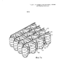
На Фиг. 6 показан другой вариант выполнения нижнего матраса, изображенного на виде сбоку в аксонометрии;In FIG. 6 shows another embodiment of the lower mattress shown in side view in a perspective view;
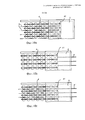
На Фиг. 7а-с показан еще один вариант выполнения нижнего матраса, изображенного, соответственно, на виде сбоку в аксонометрии и на видах сбоку, причем Фиг. 7а и 7с изображают матрас в расширенном состоянии, а Фиг. 7b изображает матрас в сжатом состоянии;In FIG. 7a-c show another embodiment of the lower mattress, shown respectively in a side view in a perspective view and in side views, with FIG. 7a and 7c show the mattress in an expanded state, and FIG. 7b shows a mattress in a compressed state;
Фиг. 8а-f иллюстрируют различные варианты выполнения нижнего матраса, содержащего упругие элементы или т.п., предназначенные для возвращения матраса в сжатое состояние или расширения матраса в расширенное состояние;FIG. 8a-f illustrate various embodiments of a lower mattress containing resilient elements or the like intended to return the mattress to a compressed state or to expand the mattress into an expanded state;
Фиг. 9а-е иллюстрируют различные варианты выполнения, в которых опорный слой (слои) размещен в различных частях матраса;FIG. 9a-e illustrate various embodiments in which the support layer (s) are placed in different parts of the mattress;
Фиг. 10а-d иллюстрируют различные варианты выполнения тянущего устройства для приведения нижнего матраса в расширенное состояние;FIG. 10a-d illustrate various embodiments of a hauling device for bringing the lower mattress into an expanded state;
Фиг. 11 иллюстрирует схематический подетальный вид в аксонометрии матраса для кровати, выполненного в соответствии с одним вариантом выполнения настоящего изобретения, имеющего дополнительные слои; иFIG. 11 illustrates a schematic detail view in perspective of a bed mattress made in accordance with one embodiment of the present invention having additional layers; and
Фиг. 12 иллюстрирует схематический подетальный вид в аксонометрии матраса для кровати, выполненного в соответствии с дополнительным вариантом выполнения настоящего изобретения.FIG. 12 illustrates a schematic detail view in perspective of a bed mattress made in accordance with a further embodiment of the present invention.
ПОДРОБНОЕ ОПИСАНИЕDETAILED DESCRIPTION
Далее изобретение проиллюстрировано с использованием матраса для кровати. Однако квалифицированные читатели поймут, что те же самые принципы и функции могут быть использованы в других типах матрасов, использующихся, например, в виде отдельного матраса, диванной подушки или т.п., например, сиденья для всех видов транспортных средств, мягкой мебели и т.п. Соответственно, когда ссылка далее делается на кровать, следует понимать, что изобретение также может быть использовано в других типах матрасов, и в частности в других типах мебели.The invention is further illustrated using a bed mattress. However, qualified readers will understand that the same principles and functions can be used in other types of mattresses, used, for example, as a separate mattress, sofa cushion or the like, for example, a seat for all types of vehicles, upholstered furniture, etc. .P. Accordingly, when reference is further made to the bed, it should be understood that the invention can also be used in other types of mattresses, and in particular in other types of furniture.
Матрас 1 для кровати, имеющий регулируемую жесткость, выполненный в соответствии с первым вариантом выполнения изобретения, схематически показан на Фиг. 1а. Матрас заключен в чехол 2, при этом виден вырезанный участок посередине внутренней части матраса. Матрас для кровати содержит верхний матрас 3, нижний матрас 4 и каркас 5. Между верхним и нижним матрасами может быть расположен дополнительный набивочный слой 7 или т.п.A
На разрезах, показанных на Фиг. 1b и Фиг. 1с, дополнительно изображен опорный слой 6, обеспечивающий частично опору для верхнего матраса на конце матраса для кровати, таком как конец для ног. Опорный слой может быть соединен с каркасом матраса для кровати или т.п., на который опирается нижний матрас. При этом, как дополнительно поясняется ниже, опорный слой также может быть соединен с боковыми опорами, соединенными с основанием нижнего матраса, основанием кровати или т.п. Опорный слой также может быть соединен с каркасом, расположенным между верхним и нижним матрасами, как например, с каркасом, окружающим по периметру нижнюю сторону верхнего матраса. В этом случае опорный слой может составлять неотъемлемую часть верхнего или нижнего матраса.In the sections shown in FIG. 1b and FIG. 1c, a
Опорный слой 6 предпочтительно является неупругим и может быть выполнен в виде жесткой конструкции, такой как пластина, обрешетка, поперечины и т.д. Кроме того, он может быть выполнен из податливых / гибких и предпочтительно неупругих элементов, таких как ткань, гибкие ленты, шнуры или т.п. В варианте выполнения, изображенном на Фиг. 1, используется пластинчатая конструкция. Тем не менее, для формирования опорного слоя также могут быть использованы упругие элементы.The
Опорный слой расположен таким образом, чтобы перекрывать подвижный конец (концы) нижнего матраса, и имеет такую протяженность, что обеспечивается поддержка для верхнего слоя над пустым участком, образующимся при сжатии нижнего матраса в сжатое состояние. Опорный слой имеет ширину, равную или почти равную ширине верхнего матраса, и длину, значительно меньшую длины верхнего матраса.The support layer is positioned so as to overlap the movable end (s) of the lower mattress, and has such a length that support is provided for the upper layer above the empty area that is formed when the lower mattress is compressed into a compressed state. The support layer has a width equal to or almost equal to the width of the upper mattress, and a length significantly less than the length of the upper mattress.
Нижний матрас 4 имеет подвижный конец 41, расположенный под опорным слоем 6, при этом противоположный конец 42 неподвижен и совмещен с соответствующим концом верхнего матраса 3.The
Опорный слой формирует отделение под верхним матрасом для размещения подвижной стороны 41 нижнего матраса, в которое нижний матрас может свободно перемещаться. Следовательно, в расширенном состоянии, при условии меньшей жесткости, отделение занято нижним матрасом, как показано на Фиг. 1b, тогда как в сжатом состоянии, при условии большей жесткости, отделение, по меньшей мере частично, не занято, как показано на Фиг. 1с. The support layer forms a compartment under the upper mattress to accommodate the
Опорный слой может удерживаться на месте различными способами, как поясняется далее.The support layer can be held in place in various ways, as explained below.
В одном варианте выполнения, показанном на подетальном изображении на Фиг. 2, каркас 5 кровати выполнен таким образом, что проходит вверх выше краев нижнего матраса 4, по меньшей мере на одном конце матраса. Этот конец предпочтительно представляет собой конец для ног матраса для кровати. Опорный слой может быть соединен с каркасом кровати с помощью гвоздей, шурупов, клея или любого другого подходящего крепежного элемента, обеспечивая, таким образом, неподвижную опору в этой части верхнего матраса 3 и возможность перемещения нижнего матраса из отделения и в отделение, образованное под верхним матрасом.In one embodiment, shown in the detail view of FIG. 2, the
В другом варианте выполнения, показанном на Фиг. 3, опорный слой прикреплен к поддерживающим сторонам 61, таким как боковые стенки, поперечины или т.п., или выполнен за одно целое с ними. Последние могут быть соединены с каркасом 5', расположенным под нижним матрасом.In another embodiment shown in FIG. 3, the support layer is attached to or supported by the supporting
В другом варианте выполнения, показанном на Фиг. 4, опорный слой соединен с каркасом кровати таким же способом, как в варианте выполнения, рассмотренном применительно к Фиг 2. В этом варианте выполнения опорный слой 6' выполнен из податливых / гибких и предпочтительно неупругих элементов, гибких лент, шнуров или т.п. Как вариант, вместо этого может быть использована гибкая ткань или т.п.In another embodiment shown in FIG. 4, the backing layer is connected to the bed frame in the same manner as in the embodiment discussed with respect to FIG. 2. In this embodiment, the backing layer 6 'is made of flexible / flexible and preferably inelastic elements, flexible tapes, cords or the like. Alternatively, flexible fabric or the like may be used instead.
Кроме того, опорный слой может быть соединен с опорной конструкцией, расположенной полностью между верхним матрасом 3 и нижним матрасом 4. Такой вариант выполнения показан на Фиг. 12. В данном случае опорный слой соединен с жестким опорным каркасом 62, расположенным по периметру верхнего матраса. Опорный слой может представлять собой, как и в предыдущих примерах, жесткую пластину, но, в качестве альтернативы, может представлять собой гибкую ткань, гибкие полосы или т.п.In addition, the support layer may be connected to the support structure located completely between the
Верхний матрас может быть разных типов, например, быть надувным элементом, упругим поролоновым элементом, упругим резиновым элементом и т.п. При этом верхний матрас предпочтительно содержит цилиндрические пружины и, предпочтительно, каждая цилиндрическая пружина по отдельности помещена в отдельный карман из покрывающего материала, формируя матрас с блоком независимых пружин. Нижний матрас может также быть разных типов. Нижний матрас может быть такого же типа, что и верхний матрас или другого.The upper mattress can be of various types, for example, be an inflatable element, an elastic foam element, an elastic rubber element, etc. Moreover, the upper mattress preferably contains coil springs and, preferably, each coil spring is individually placed in a separate pocket of covering material, forming a mattress with a block of independent springs. The bottom mattress can also be of different types. The lower mattress may be of the same type as the upper mattress or another.
Предпочтительно, нижний матрас представляет собой матрас с блоком независимых пружин, содержащий цилиндрические пружины, помещенные в карманы. Наиболее предпочтительно, матрас с блоком независимых пружин содержит параллельные ряды, взаимно соединенных бок о бок, при этом каждый ряд имеет непрерывные оболочки, а каждая оболочка содержит цилиндрическую пружину, при этом расширение матраса в расширенное состояние осуществляется по меньшей мере в одном из направлений, в направлении, параллельном рядам, и в направлении, перпендикулярном рядам. Каждый ряд предпочтительно выполнен из непрерывного покрывающего материала, а разделяющее пространство между соседними карманами сформировано поперечными разделяющими соединительными элементами. Эти разделяющие соединительные элементы, а также продольные соединительные элементы могут быть сформированы с использованием любого клеевого соединения, сварки, соединения скобами, сшиванием или любой их комбинацией. В предпочтительном варианте выполнения используется сварка. В настоящем изобретении могут быть использованы цилиндрические пружины разных размеров, и в принципе могут быть использованы пружины любого заданного размера, большие или небольшие. При этом предпочтительно, чтобы цилиндрические пружины имели диаметр в пределах от 2 до 10 см, предпочтительно в пределах от 4 до 8 см, например, 6 см. Кроме того, цилиндрические пружины предпочтительно изготавливают из спиральной скрученной проволоки. Пружины предпочтительно содержат по меньшей мере три витка и, предпочтительно, меньше 10 витков. Кроме того, предпочтительно, чтобы они были выполнены из спиральной проволоки толщиной от 0,5 до 3,0 мм, предпочтительно от 1,25 до 2,50 мм. Предпочтительно, чтобы пружины имели почти цилиндрическую форму, то есть форму с меньшим количеством витков вверху и внизу. Матрасы этих типов по существу известны.Preferably, the bottom mattress is a mattress with a block of independent springs, containing coil springs placed in pockets. Most preferably, the mattress with a block of independent springs contains parallel rows mutually connected side by side, with each row having continuous shells and each shell containing a coil spring, with the mattress expanding into an expanded state in at least one of the directions, a direction parallel to the rows and in a direction perpendicular to the rows. Each row is preferably made of a continuous covering material, and the dividing space between adjacent pockets is formed by transverse dividing connecting elements. These separating connecting elements, as well as longitudinal connecting elements, can be formed using any adhesive bonding, welding, stapling, stitching, or any combination thereof. In a preferred embodiment, welding is used. Coil springs of different sizes can be used in the present invention, and in principle springs of any given size, large or small, can be used. In this case, it is preferable that the coil springs have a diameter in the range of 2 to 10 cm, preferably in the range of 4 to 8 cm, for example 6 cm. In addition, the coil springs are preferably made of twisted spiral wire. The springs preferably contain at least three turns and, preferably, less than 10 turns. In addition, it is preferable that they be made of spiral wire with a thickness of 0.5 to 3.0 mm, preferably 1.25 to 2.50 mm. Preferably, the springs have an almost cylindrical shape, that is, a shape with fewer turns at the top and bottom. Mattresses of these types are essentially known.
Один тип матраса, пригодный для использования в качестве нижнего матраса, раскрыт в патенте США №8176589 настоящего заявителя, причем указанный документ полностью включен в данный документ в качестве ссылки. Такой матрас с блоком независимых пружин изображен на Фиг. 5а и 5b. Этот матрас с блоком независимых пружин содержит карманы 51, расположенные рядами 52. В каждом кармане имеется цилиндрическая пружина. Каждый ряд состоит из непрерывного покрывающего материала, и карманы сформированы с помощью разделяющих соединительных элементов 53, например, с помощью сварки. Ряды соединены друг с другом параллельно бок о бок с помощью соединительных элементов 55. Эти соединительные элементы могут быть выполнены с помощью склеивающего вещества, но, как вариант, они могут быть выполнены с помощью сварки, Velcro или т.п. Кроме того, карманы имеют растягиваемые отверстия 54, обеспечивающие сеткообразную структуру поверхности. Это обеспечивает разделение рядов друг от друга.One type of mattress suitable for use as a lower mattress is disclosed in US Patent No. 8176589 to the present applicant, the document being incorporated herein by reference in its entirety. Such a mattress with a block of independent springs is shown in FIG. 5a and 5b. This mattress with a block of independent springs contains
Другой тип матраса, пригодный для использования в качестве нижнего матраса, описан в патенте США №7048263 настоящего заявителя, причем указанный документ полностью включен в данный документ в качестве ссылки. Такой матрас показан на Фиг. 6. Этот матрас имеет такую же общую конструкцию, как и в предыдущем примере с цилиндрическими пружинами, расположенными в карманах 51, образующих параллельно соединенные друг с другом ряды 52. При этом в этом варианте выполнения в каждом ряду отделяющий промежуток между карманами / пружинами увеличен. Это можно осуществить путем выполнения двух разнесенных разделяющих соединительных элементов 53' или, в качестве альтернативы, с помощью широких разделяющих соединительных элементов или т.п. Таким образом, между соседними пружинами / карманами в каждом ряду образуется отделяющий промежуток, что позволяет матрасу расширяться и сжиматься в направлении рядов.Another type of mattress suitable for use as a lower mattress is described in US Pat. No. 7,048,263 to the present applicant, which document is incorporated herein by reference in its entirety. Such a mattress is shown in FIG. 6. This mattress has the same general construction as in the previous example with coil springs located in
Другой тип матраса, пригодный для использования в качестве нижнего матраса, описан в заявке на патент США №2007/124865 настоящего заявителя, причем указанный документ полностью включен в данный документ в качестве ссылки. Такой матрас показан на Фиг. 7. Этот матрас имеют такую же общую конструкцию, как в предыдущем примере с цилиндрическими пружинами, расположенными в карманах 51, образующих параллельно соединенные друг с другом ряды 52. Кроме того, отделяющий промежуток между карманами / пружинами в каждом ряду увеличен, что можно осуществить путем выполнения двух разнесенных разделяющих соединительных элементов 53' или т.п. Для дополнительного увеличения гибкости рядов предусмотрены щелевые отверстия 56, расположенные между карманами и между разделяющими соединительными элементами 53'. Щелевые отверстия предпочтительно полностью заключены в материале, без открытых концов. Фиг. 7b иллюстрирует этот матрас в сжатом состоянии, в то время как Фиг. 7с иллюстрируют тот же матрас в расширенном состоянии.Another type of mattress suitable for use as a lower mattress is described in U.S. Patent Application No. 2007/124865 of the present applicant, which document is incorporated herein by reference in its entirety. Such a mattress is shown in FIG. 7. This mattress has the same general construction as in the previous example with coil springs located in
Предпочтительно, нижний матрас дополнительно содержит по меньшей мере один упругий элемент, проходящий между указанной подвижной стороной и указанной противоположной стороной нижнего матраса, при этом указанный по меньшей мере один упругий элемент выполнен с возможностью приложения силы сжатия для приведения нижнего матраса в сжатое состояние. Таким образом, нижний матрас принимает сжатое состояние при отсутствии внешнего усилия. Это упрощает использование матраса и обеспечивает равномерное распределение пружин в нижнем матрасе также в любом промежуточном состоянии между расширенным состоянием и сжатым состоянием. Упругим элементом может быть, например, лента, шнур, веревка или подобное изделие, выполненное из упругого материала. Предпочтительно, предусмотрено несколько упругих элементов, распределенных по нижнему матрасу или в нижнем матрасе. Кроме того, предпочтительно, чтобы каждый упругий элемент был соединен с нижним матрасом в нескольких распределенных точках соединения. В частности, такие упругие элементы могут сочетаться с матрасом с блоком независимых пружин любого типа, рассмотренного выше применительно к Фиг. 5-7.Preferably, the lower mattress further comprises at least one elastic element extending between said movable side and said opposite side of the lower mattress, wherein said at least one elastic element is capable of applying a compressive force to bring the lower mattress into a compressed state. Thus, the lower mattress assumes a compressed state in the absence of external force. This simplifies the use of the mattress and ensures uniform distribution of the springs in the lower mattress also in any intermediate state between the expanded state and the compressed state. The elastic element may be, for example, a tape, cord, rope or similar product made of an elastic material. Preferably, several elastic elements are provided distributed over the lower mattress or in the lower mattress. In addition, it is preferable that each resilient element is connected to the lower mattress at several distributed connection points. In particular, such elastic elements can be combined with a mattress with a block of independent springs of any type discussed above with respect to FIG. 5-7.
На Фиг. 8 показаны некоторые альтернативные способы выполнения таких упругих элементов 57.In FIG. 8 shows some alternative methods for making such
На Фиг. 8а показан матрас с блоком независимых пружин, в котором упругие элементы 57 расположены в верхней и в нижней части нижнего матраса. В изображенном примере упругие элементы расположены как в верхней, так и в нижней части нижнего матраса, но, в качестве альтернативы, упругие элементы могут быть расположены только в верхней или только в нижней части. Кроме того, расположение упругих элементов в данном случае совпадает с расположением рядов. При этом в качестве альтернативы или дополнительно, упругие элементы могут быть расположены перпендикулярно рядам. Кроме того, в этом примере упругие элементы могут быть расположены вдоль каждого ряда, однако, может быть использовано меньшее количество упругих элементов. Упругие элементы предпочтительно соединены с рядами в нескольких точках соединения, например, с каждым карманом, с которым они входят в контакт.In FIG. 8a shows a mattress with a block of independent springs, in which
Как вариант или дополнительно, упругие элементы 57 могут быть расположены по бокам матраса и между рядами. Такой вариант выполнения показан на Фиг. 8b. В этом варианте выполнения упругие элементы предусмотрены между каждой парой рядов. Кроме того, может быть использовано меньшее количество упругих элементов. Пример такого варианта выполнения показан на Фиг. 8с.Alternatively or additionally,
В вариантах выполнения, изображенных на Фиг. 8а-с, упругие элементы 57 расположены параллельно рядам матраса. Однако сжатие и расширение матраса, как уже обсуждалось ранее, осуществляется в направлении, перпендикулярном направлению рядов. В таком матрасе упругие элементы могут быть ориентированы перпендикулярно направлению рядов. Такие варианты выполнения показаны на Фиг. 8d.In the embodiments depicted in FIG. 8a-c, the
В вариантах выполнения, рассмотренных со ссылками на Фиг. 8а-d, упругие элементы выполнены с возможностью приложения усилия для приведения матраса в сжатое состояние. При этом упругие элементы могут быть выполнены с возможностью приложения усилия для приведения матраса в расширенное состояние. Такой вариант выполнения показан на Фиг. 8е. При этом упругие элементы 57' могут быть выполнены из упругого сжимаемого материала, например, из латекса или полиэфира, с возможностью сжатия между рядами при сжатии матраса, обеспечивая, тем самым, силу для растяжения матраса при снятии силы сжатия. В иллюстративном примере, показанном на Фиг. 8е, упругий сжимаемый материал размещен между соседними пружинами в одном и том же ряду / линии матраса. Тем не менее, дополнительно или в качестве альтернативы, упругий сжимаемый материал может быть размещен между соседними пружинами в соседних рядах / линиях, т.е. расположен между соседними рядами / линиями, а не на одной линии с рядами / линиями.In the embodiments described with reference to FIG. 8a-d, the elastic elements are configured to apply force to bring the mattress into a compressed state. In this case, the elastic elements can be made with the possibility of applying force to bring the mattress into an expanded state. Such an embodiment is shown in FIG. 8th. In this case, the elastic elements 57 'can be made of compressible elastic material, for example, latex or polyester, with the possibility of compression between the rows when compressing the mattress, thereby providing a force for stretching the mattress when removing the compressive force. In the illustrative example shown in FIG. 8e, elastic compressible material is placed between adjacent springs in the same row / line of the mattress. However, in addition or alternatively, an elastic compressible material can be placed between adjacent springs in adjacent rows / lines, i.e. located between adjacent rows / lines, and not on the same line as the rows / lines.
Кроме того, для приведения матраса в расширенное и/или сжатое состояние могут быть также использованы другие типы элементов. Например, как показано на Фиг. 8f, между пружинами могут быть расположены надувные трубки 57'', подушки и т.п. При накачивании воздухом трубок 57'' матрас приводится в расширенное состояние, а при выпускании и удалении воздуха из них матрас приводится в сжатое состояние. Таким образом, при уменьшении внешнего усилия данный пневматический принцип и такие надувные элементы могут быть использованы для возврата матраса к сжатому и/или расширенному состоянию. Однако он также может быть использован для замены других средств, использующихся для перемещения матраса из сжатого состояния в расширенное состояние, и наоборот и, таким образом, использоваться как единственное средство для перемещения между состояниями.In addition, other types of elements may also be used to bring the mattress into an expanded and / or compressed state. For example, as shown in FIG. 8f, 57 '' inflatable tubes, cushions and the like may be located between the springs When the 57 '' tubes are inflated with air, the mattress is brought into an expanded state, and when the air is released and removed from them, the mattress is brought into a compressed state. Thus, with a decrease in external force, this pneumatic principle and such inflatable elements can be used to return the mattress to a compressed and / or expanded state. However, it can also be used to replace other means used to move the mattress from a compressed state to an expanded state, and vice versa, and thus be used as the only means to move between states.
В иллюстративном примере в соответствии с Фиг. 8f, надувные элементы проходят перпендикулярно рядам / линиям матраса и расположены между соседними пружинами в том же самом ряду / линии. При этом дополнительно, или в качестве альтернативы, надувные элементы могут проходить параллельно рядам / линиям, в результате чего надувные элементы расположены между соседними пружинами в соседних рядах, т.е. расположены между соседними рядами / линиями.In an illustrative example in accordance with FIG. 8f, the inflatable elements extend perpendicular to the rows / lines of the mattress and are located between adjacent springs in the same row / line. In this case, in addition, or as an alternative, the inflatable elements can extend parallel to the rows / lines, as a result of which the inflatable elements are located between adjacent springs in adjacent rows, i.e. located between adjacent rows / lines.
В рассмотренных выше вариантах выполнения опорный слой расположен на конце для ног матраса для кровати. В этой области обычно отсутствует необходимость регулирования жесткости. Кроме того, в кровати эта часть матраса часто используется также для сидения, при этом повышенная жесткость, обеспеченная за счет опорного слоя, улучшает комфорт при сидении.In the above embodiments, the support layer is located at the foot end of the bed mattress. In this area, there is usually no need to control rigidity. In addition, in bed, this part of the mattress is often also used for sitting, while the increased stiffness provided by the support layer improves sitting comfort.
При этом дополнительно, или в качестве альтернативы, опорный слой может быть расположен вдоль длинных сторон матраса для кровати. К тому же, это не влияет негативно на комфорт во время сна, так как наружные края, как правило, во время сна не используются. Напротив, повышенная жесткость в направлении краев зачастую является эффективной, так как она, как и в предыдущем случае, улучшает комфорт при сидении на стороне матраса, а также снижает риск случайного падения с кровати. Размещение опорного слоя вдоль одной или обеих длинных сторон устройства с матрасом также предпочтительно при использовании матрасов в диванах, кушетках и т.п.Moreover, in addition, or as an alternative, the backing layer may be located along the long sides of the bed mattress. In addition, this does not negatively affect comfort during sleep, since the outer edges, as a rule, are not used during sleep. On the contrary, increased stiffness in the direction of the edges is often effective, since it, as in the previous case, improves comfort when sitting on the side of the mattress, and also reduces the risk of accidentally falling out of bed. Placing the support layer along one or both long sides of the device with the mattress is also preferable when using mattresses in sofas, couches, etc.
На Фиг. 9а-е схематически проиллюстрировано различное расположение опорного слоя. На Фиг. 9а опорный слой 6 расположен на конце для ног матраса для кровати, как в рассмотренных выше примерах. На Фиг. 9b опорный слой 6 расположен как на конце для головы, так и на конце для ног, обеспечивая, тем самым, перемещение нижнего матраса на обоих концах. На Фиг. 9с опорные слои 6 расположены на обеих длинных сторонах матраса, обеспечивая сжатие и расширение нижнего матраса в ширину. На Фиг. 9d показана комбинация вариантов выполнения в соответствии с Фиг. 9b и 9с, обеспечивающая сжатие и расширение нижнего матраса, как в ширину, так и в длину. И наконец, на Фиг. 9е показан вариант выполнения, в котором опорный слой 6 расположен только на одной длинной стороне матраса, обеспечивая неподвижность противоположного конца нижнего матраса.In FIG. 9a-e schematically illustrates a different arrangement of the support layer. In FIG. 9a, the
Кроме того, устройство с матрасом предпочтительно содержит тянущее или толкающее устройство, соединенное по меньшей мере с одной подвижной стороной, чтобы прикладывать тянущее или толкающее усилие для приведения нижнего матраса в расширенное состояние. Тянущее или толкающее устройство может представлять собой одну или несколько веревок, шнуров или т.п., соединенных со стороной нижнего матраса или внутри нижнего матраса. Такое устройство является экономически выгодным и, в частности, подходит для выполнения операций вручную. Веревки / шнуры могут быть, например, зафиксированы в соответствующем вытянутом положении с помощью запирающего устройства, для соединения друг с другом или закрепления каким-либо иным образом. При этом веревками / шнурами можно управлять с помощью электродвигателя или т.п. Кроме того, подвижная сторона нижнего матраса может быть соединена с жестким тянущим или толкающим элементом, который может перемещаться автоматически, с помощью электродвигателя или т.п. или вручную, с помощью винтового устройства или т.п. Например, может быть использован подающий винт или ходовой винт. Ручку, колесо или любой другой тип ручки можно затем поворачивать вручную, поворачивая, тем самым, винт, что приводит к соответствующему перемещению жесткого тянущего элемента.In addition, the device with the mattress preferably comprises a pulling or pushing device connected to at least one movable side to apply a pulling or pushing force to bring the lower mattress into an expanded state. The pulling or pushing device may be one or more ropes, cords or the like connected to the side of the lower mattress or inside the lower mattress. Such a device is cost-effective and, in particular, is suitable for manual operations. The ropes / cords can, for example, be fixed in the corresponding elongated position using a locking device, for connecting to each other or for securing in some other way. In this case, ropes / cords can be controlled using an electric motor or the like. In addition, the movable side of the lower mattress can be connected to a rigid pulling or pushing element, which can be moved automatically, using an electric motor or the like. or manually, using a screw device or the like. For example, a feed screw or a lead screw may be used. The handle, wheel or any other type of handle can then be turned manually, thereby turning the screw, which leads to a corresponding movement of the rigid pulling element.
Некоторые варианты выполнения таких тянущих устройств будут проиллюстрированы ниже.Some embodiments of such pulling devices will be illustrated below.
На Фиг. 10а показаны манипулирующие элементы 8, например, гибкие элементы, такие как веревки или шнуры, или более жесткие элементы, такие как стержни или т.п., прикрепленные к подвижной стороне 41 нижнего матраса 4, расположенного под опорным слоем 6. Манипулирующие элементы 8 проходят внутри или ниже нижнего матраса и к ним имеется доступ с противоположной стороны. При вытягивании манипулирующих элементов 8 матрас будет сжиматься, при этом подвижные элементы могут быть закреплены любым подходящим способом с целью фиксирования матраса в необходимом промежуточном или сжатом состоянии. Подвижная сторона матраса может быть соединена с упругими элементами (не показаны), такими как пружины, для возвращения матраса в расширенное состояние. В качестве альтернативы или дополнительно, манипулирующие элементы 8 могут быть относительно жесткими и использоваться взамен или в дополнение для перемещения подвижной стороны в расширенное состояние. При этом матрас может содержать гибкие элементы, как описано выше, предназначенные для приведения нижнего матраса в сжатое состояние.In FIG. 10a,
На Фиг. 10b показано аналогичное устройство. В данном случае манипулирующие элементы 8' соединены с подвижной стороной 41 нижнего матраса, но вместе с тем смещены от указанной стороны, при этом при перемещении манипулирующих элементов внутрь матрас сжимается, а при вытягивании манипулирующих элементов матрас расширяется.In FIG. 10b shows a similar device. In this case, the manipulating elements 8 'are connected to the
На Фиг. 10 с показано устройство с манипулирующими элементами 8'', такими как веревки или шнуры или т.п., проходящими в обоих направлениях от подвижного конца 41 нижнего матраса 4 и к которым имеется доступ с обоих концов. Это устройство может быть использовано для перемещения подвижного конца в сжатое состояние, как в варианте выполнения в соответствии с Фиг. 10а, и для вытягивания подвижного конца в расширенное состояние с другой стороны. Таким образом, может отсутствовать необходимость в каких-либо упругих или эластичных элементах, предназначенных для приведения нижнего матраса в сжатое состояние.In FIG. 10 s shows a device with handling
На Фиг. 10d показано автоматизированное устройство. При этом подвижный конец 41 соединен с жестким боковым элементом 8а, который, в свою очередь, присоединен при помощи перемещающей штанги 8с к электрическому перемещающему устройству, например, к электродвигателю, электронасосу 8b или т.п.In FIG. 10d shows an automated device. In this case, the
Помимо верхнего и нижнего матрасов 3 и 4 и каркаса 5 могут быть предусмотрены дополнительный матрас или набивочные слои. Один из таких примеров схематически показан на Фиг. 11, где показана поверхность верхнего набивочного слоя 7b, при этом промежуточный матрас или набивочный слой 7а расположен между верхним и нижним матрасами, а вокруг нижнего матраса выполнены стороны 7с набивки или матраса. Возможно использование меньшего или большего количества набивки или слоев матраса.In addition to the upper and
Специалисту понятно, что настоящее изобретение никоим образом не ограничивается предпочтительными вариантами выполнения, описанными выше. Напротив, многие модификации и изменения возможны в пределах объема прилагаемой формулы изобретения. Например, и верхний, и нижний матрасы могут быть других типов, нежели матрас с блоком независимых пружин, как например, упругими элементами, образованными из поролона, резины, пружин, надувных элементов и т.п. Кроме того, нижний матрас может сжиматься и расширяться в различных направлениях, при этом опорный слой может удерживаться на месте различными способами. Дополнительно, жесткость устройства с матрасом может регулироваться либо вручную, либо электрически. Такие очевидные варианты должны быть рассмотрены как включенные в изобретение, как определено в прилагаемой формуле изобретения.One skilled in the art will appreciate that the present invention is in no way limited to the preferred embodiments described above. On the contrary, many modifications and changes are possible within the scope of the attached claims. For example, both the upper and lower mattresses can be of different types than a mattress with a block of independent springs, such as elastic elements formed of foam rubber, rubber, springs, inflatable elements, etc. In addition, the lower mattress can be compressed and expanded in different directions, while the support layer can be held in place in various ways. Additionally, the rigidity of the device with the mattress can be adjusted either manually or electrically. Such obvious options should be considered as included in the invention, as defined in the attached claims.
Claims (22)
Applications Claiming Priority (5)
| Application Number | Priority Date | Filing Date | Title |
|---|---|---|---|
| EP14161718.3A EP2923610B1 (en) | 2014-03-26 | 2014-03-26 | Mattress arrangement, such as a bed, having adjustable firmness |
| EP14161718.3 | 2014-03-26 | ||
| BRBR102015001231-4 | 2015-01-19 | ||
| BR102015001231-4A BR102015001231B1 (en) | 2014-03-26 | 2015-01-19 | mattress arrangement and method or adaptation of the firmness of a mattress arrangement |
| PCT/EP2015/056603 WO2015144836A1 (en) | 2014-03-26 | 2015-03-26 | Mattress arrangement, such as a bed, having adjustable firmness |
Publications (3)
| Publication Number | Publication Date |
|---|---|
| RU2016135341A RU2016135341A (en) | 2018-04-27 |
| RU2016135341A3 RU2016135341A3 (en) | 2018-07-23 |
| RU2683365C2 true RU2683365C2 (en) | 2019-03-28 |
Family
ID=50389843
Family Applications (1)
| Application Number | Title | Priority Date | Filing Date |
|---|---|---|---|
| RU2016135341A RU2683365C2 (en) | 2014-03-26 | 2015-03-26 | Device with a mattress, such as a bed having adjustable firmness |
Country Status (12)
| Country | Link |
|---|---|
| US (1) | US10624465B2 (en) |
| EP (1) | EP2923610B1 (en) |
| JP (1) | JP6640104B2 (en) |
| CN (1) | CN106231958B (en) |
| AU (1) | AU2015238333B2 (en) |
| BR (1) | BR102015001231B1 (en) |
| CA (1) | CA2943267C (en) |
| MX (1) | MX2016012402A (en) |
| NZ (1) | NZ723650A (en) |
| PL (1) | PL2923610T3 (en) |
| RU (1) | RU2683365C2 (en) |
| WO (1) | WO2015144836A1 (en) |
Cited By (4)
| Publication number | Priority date | Publication date | Assignee | Title |
|---|---|---|---|---|
| RU190787U1 (en) * | 2019-04-23 | 2019-07-12 | Артем Андреевич Монахов | Spring mattress |
| RU190839U1 (en) * | 2019-04-23 | 2019-07-15 | Артем Андреевич Монахов | MATTRESS |
| RU2701259C1 (en) * | 2019-04-23 | 2019-09-25 | Артем Андреевич Монахов | Mattress manufacturing method |
| RU217228U1 (en) * | 2022-11-10 | 2023-03-23 | Владимир Викторович Михайлов | Self-leveling orthopedic mattress |
Families Citing this family (14)
| Publication number | Priority date | Publication date | Assignee | Title |
|---|---|---|---|---|
| US9900801B2 (en) | 2014-08-08 | 2018-02-20 | Parallel Wireless, Inc. | Congestion and overload reduction |
| US10357116B2 (en) * | 2015-06-22 | 2019-07-23 | Zeplus, Llc | Pocketed foam systems and methods |
| RU2754528C2 (en) * | 2016-06-08 | 2021-09-03 | Бедгир, Ллк | Spring block with independent spring-loading |
| CN106617883B (en) * | 2016-12-07 | 2018-11-16 | 重庆佐恩家具有限公司 | Soft bed |
| US10334958B2 (en) * | 2017-05-09 | 2019-07-02 | L&P Property Management Company | Glueless pocketed spring assembly with improved airflow |
| DK3403540T3 (en) * | 2017-05-15 | 2020-06-08 | Starsprings Ab | MADRAS ARRANGEMENTS, SUCH AS A BED, WITH ADJUSTABLE FASTENCE |
| US10512340B2 (en) | 2017-05-31 | 2019-12-24 | L&P Property Management Company | Pocketed spring assembly comprising strings of springs with tabs |
| CN108244878A (en) * | 2018-03-26 | 2018-07-06 | 武汉思瀚智能有限公司 | Digitize adjustable elastic device, system and body bearing device |
| US11013340B2 (en) * | 2018-05-23 | 2021-05-25 | L&P Property Management Company | Pocketed spring assembly having dimensionally stabilizing substrate |
| EP3583868B1 (en) | 2018-06-19 | 2023-11-29 | Starsprings AB | Low density pocket spring mattress with integrated cushioning pads |
| DK3586682T3 (en) * | 2018-06-25 | 2021-02-01 | Starsprings Ab | Strength adjusting device for a bed or a seating device |
| ES2809494B2 (en) * | 2019-09-04 | 2021-11-15 | Pikolin S L | ADJUSTABLE FIRMING DEVICE AND REST FURNITURE INCLUDING SUCH DEVICE |
| CN115103615A (en) * | 2020-02-13 | 2022-09-23 | 紫色创新有限责任公司 | Composite mattress with air chamber |
| NL2029662B1 (en) * | 2021-11-08 | 2023-06-05 | Koninklijke Auping B V | A method to produce a mattress, a mattress obtainable with this method and a system for applying this method |
Citations (5)
| Publication number | Priority date | Publication date | Assignee | Title |
|---|---|---|---|---|
| US3252170A (en) * | 1963-08-08 | 1966-05-24 | James R Frye | Variable firmness mattress |
| US3738409A (en) * | 1971-01-27 | 1973-06-12 | Welding Engineers | Apparatus for flash-concentrating viscous liquids |
| DE3738272A1 (en) * | 1987-11-11 | 1989-05-24 | Hueser Schlaraffia Werke | Interior-sprung mattress |
| FR2750584A1 (en) * | 1996-07-03 | 1998-01-09 | Productions Marcel Maceron Et | Interior sprung unit, especially mattress |
| RU119217U1 (en) * | 2011-01-18 | 2012-08-20 | БИО-Текстима Кфт | MULTILAYER SPRING MATTRESS |
Family Cites Families (26)
| Publication number | Priority date | Publication date | Assignee | Title |
|---|---|---|---|---|
| US2822032A (en) * | 1956-01-18 | 1958-02-04 | Gen Motors Corp | Seat spring tension adjuster |
| US3273877A (en) * | 1965-04-26 | 1966-09-20 | Gen Motors Corp | Seat structure |
| US3340548A (en) | 1965-10-01 | 1967-09-12 | Wortso Corp | Bedding prescription apparatus |
| US3739409A (en) * | 1971-08-03 | 1973-06-19 | Chitton K | Adjustable mattress |
| JPS54126163A (en) | 1978-03-20 | 1979-10-01 | Nippon Betsudo Seizou Kk | Internallpressureeadjusted bed |
| AU551300B2 (en) | 1982-03-05 | 1986-04-24 | Trec International Ltd. | Adjustable spring mattress |
| JPS6421660U (en) | 1987-07-28 | 1989-02-03 | ||
| US5105488A (en) * | 1990-04-18 | 1992-04-21 | Simmons Company | Bedding configuration having variable support characteristics |
| US5113539A (en) * | 1991-07-31 | 1992-05-19 | Strell Brian M | Adjustable firmness coil spring mattress with inflatable tubes |
| US5469590A (en) * | 1994-03-04 | 1995-11-28 | The Spring Air Company | Mattress with compressible support members |
| US5987678A (en) | 1995-05-10 | 1999-11-23 | Simmons Company | Multiple firmness mattress |
| DE19826436A1 (en) | 1998-06-16 | 1999-12-23 | Hoffmann Gmbh | Upholstered furniture with adjustable seat height and/or hardness |
| JP2001145545A (en) * | 1999-11-19 | 2001-05-29 | Simmons Corp | Cushion comprising mattress or the like |
| SE0004412L (en) | 2000-11-30 | 2001-11-26 | Stjernfjaedrar Ab | Separate pocket mattress |
| GB0320215D0 (en) | 2003-08-29 | 2003-10-01 | Harrison Bedding Ltd | Spring units |
| SE527152C2 (en) | 2003-12-12 | 2006-01-10 | Stjernfjaedrar Ab | Separate pocket mattress with cut strings, as well as method and apparatus for its manufacture |
| SE530333C2 (en) | 2007-01-12 | 2008-05-06 | Stjernfjaedrar Ab | Pocket spring mattress for bed, has springs located in pockets containing offset stretch holes |
| SE531517C2 (en) * | 2007-09-25 | 2009-05-05 | Carpe Diem Beds Of Sweden Ab | Device by bed |
| SE532788C2 (en) * | 2007-10-23 | 2010-04-13 | Stjernfjaedrar Ab | Variable size bed and a vehicle comprising such a bed |
| WO2009102361A1 (en) * | 2008-02-14 | 2009-08-20 | Kingsdown, Inc. | Apparatuses and methods providing variable support and variable comfort control of a sleep system and automatic adjustment thereof |
| EP2540194B1 (en) * | 2008-02-14 | 2014-04-30 | Kingsdown, Inc. | Apparatuses and methods for evaluating a person for a sleep system |
| US8533879B1 (en) | 2008-03-15 | 2013-09-17 | Stryker Corporation | Adaptive cushion method and apparatus for minimizing force concentrations on a human body |
| DK2222207T3 (en) | 2008-09-30 | 2011-12-05 | Ls Bedding | Bed System |
| EP2245967B1 (en) | 2009-04-27 | 2013-03-20 | PASS of Sweden AB | A furniture device adapted to receive the weight of a being |
| US9022474B2 (en) * | 2009-07-06 | 2015-05-05 | L&P Property Management Company | Adjustable foundation for a seating unit |
| EP2762042B1 (en) * | 2013-02-01 | 2018-11-14 | Starsprings AB | Bed having zones with adjustable height/firmness |
-
2014
- 2014-03-26 PL PL14161718T patent/PL2923610T3/en unknown
- 2014-03-26 EP EP14161718.3A patent/EP2923610B1/en active Active
-
2015
- 2015-01-19 BR BR102015001231-4A patent/BR102015001231B1/en not_active IP Right Cessation
- 2015-03-26 WO PCT/EP2015/056603 patent/WO2015144836A1/en active Application Filing
- 2015-03-26 MX MX2016012402A patent/MX2016012402A/en unknown
- 2015-03-26 JP JP2016558361A patent/JP6640104B2/en active Active
- 2015-03-26 CA CA2943267A patent/CA2943267C/en active Active
- 2015-03-26 AU AU2015238333A patent/AU2015238333B2/en active Active
- 2015-03-26 RU RU2016135341A patent/RU2683365C2/en active
- 2015-03-26 CN CN201580014591.0A patent/CN106231958B/en active Active
- 2015-03-26 NZ NZ723650A patent/NZ723650A/en unknown
- 2015-03-26 US US15/122,809 patent/US10624465B2/en active Active
Patent Citations (5)
| Publication number | Priority date | Publication date | Assignee | Title |
|---|---|---|---|---|
| US3252170A (en) * | 1963-08-08 | 1966-05-24 | James R Frye | Variable firmness mattress |
| US3738409A (en) * | 1971-01-27 | 1973-06-12 | Welding Engineers | Apparatus for flash-concentrating viscous liquids |
| DE3738272A1 (en) * | 1987-11-11 | 1989-05-24 | Hueser Schlaraffia Werke | Interior-sprung mattress |
| FR2750584A1 (en) * | 1996-07-03 | 1998-01-09 | Productions Marcel Maceron Et | Interior sprung unit, especially mattress |
| RU119217U1 (en) * | 2011-01-18 | 2012-08-20 | БИО-Текстима Кфт | MULTILAYER SPRING MATTRESS |
Cited By (4)
| Publication number | Priority date | Publication date | Assignee | Title |
|---|---|---|---|---|
| RU190787U1 (en) * | 2019-04-23 | 2019-07-12 | Артем Андреевич Монахов | Spring mattress |
| RU190839U1 (en) * | 2019-04-23 | 2019-07-15 | Артем Андреевич Монахов | MATTRESS |
| RU2701259C1 (en) * | 2019-04-23 | 2019-09-25 | Артем Андреевич Монахов | Mattress manufacturing method |
| RU217228U1 (en) * | 2022-11-10 | 2023-03-23 | Владимир Викторович Михайлов | Self-leveling orthopedic mattress |
Also Published As
| Publication number | Publication date |
|---|---|
| CA2943267A1 (en) | 2015-10-01 |
| EP2923610A1 (en) | 2015-09-30 |
| PL2923610T3 (en) | 2020-08-10 |
| JP6640104B2 (en) | 2020-02-05 |
| WO2015144836A1 (en) | 2015-10-01 |
| BR102015001231B1 (en) | 2021-01-05 |
| CA2943267C (en) | 2020-11-03 |
| EP2923610B1 (en) | 2020-03-18 |
| US10624465B2 (en) | 2020-04-21 |
| RU2016135341A3 (en) | 2018-07-23 |
| AU2015238333A1 (en) | 2016-09-15 |
| JP2017508547A (en) | 2017-03-30 |
| CN106231958A (en) | 2016-12-14 |
| RU2016135341A (en) | 2018-04-27 |
| BR102015001231A2 (en) | 2015-12-01 |
| US20170086597A1 (en) | 2017-03-30 |
| MX2016012402A (en) | 2017-06-08 |
| NZ723650A (en) | 2022-07-29 |
| AU2015238333B2 (en) | 2019-06-20 |
| CN106231958B (en) | 2020-06-30 |
Similar Documents
| Publication | Publication Date | Title |
|---|---|---|
| RU2683365C2 (en) | Device with a mattress, such as a bed having adjustable firmness | |
| US10517407B2 (en) | Adjustable comfort mattress system and processes | |
| RU2765457C2 (en) | Mattress device, such as bed, with adjustable stiffness | |
| US20130042413A1 (en) | Mattress with concealed massage units | |
| US11213139B2 (en) | Composite mattresses with air chambers | |
| EP3386349B1 (en) | Efficient mattress having low pressure and alignment | |
| CN112135551A (en) | Hardness control device for a bed or seat arrangement | |
| KR20160101646A (en) | mattress | |
| RU2780791C2 (en) | Rigidity adjustment device for lying or sitting structure | |
| KR102153753B1 (en) | Bed frame with double mattress function | |
| RU170148U1 (en) | Orthopedic bed with a bed consisting of movable mechanical segments supporting the pelvis, lower back, back, neck and head of the user | |
| UA28233U (en) | Item of upholstereded furniture |