RU2683205C1 - Electrocardiography monitoring system and method - Google Patents
Electrocardiography monitoring system and method Download PDFInfo
- Publication number
- RU2683205C1 RU2683205C1 RU2016125333A RU2016125333A RU2683205C1 RU 2683205 C1 RU2683205 C1 RU 2683205C1 RU 2016125333 A RU2016125333 A RU 2016125333A RU 2016125333 A RU2016125333 A RU 2016125333A RU 2683205 C1 RU2683205 C1 RU 2683205C1
- Authority
- RU
- Russia
- Prior art keywords
- capacitive sensors
- output signals
- capacitive
- ecg
- connection
- Prior art date
Links
- 238000000034 method Methods 0.000 title claims abstract description 37
- 238000012544 monitoring process Methods 0.000 title claims abstract description 20
- 238000002565 electrocardiography Methods 0.000 title abstract description 6
- 239000013598 vector Substances 0.000 claims description 19
- 238000004590 computer program Methods 0.000 claims description 8
- 238000009826 distribution Methods 0.000 claims description 8
- 238000005259 measurement Methods 0.000 abstract description 13
- 230000008878 coupling Effects 0.000 abstract description 6
- 238000010168 coupling process Methods 0.000 abstract description 6
- 238000005859 coupling reaction Methods 0.000 abstract description 6
- 230000000694 effects Effects 0.000 abstract description 3
- 239000003814 drug Substances 0.000 abstract 1
- 239000000126 substance Substances 0.000 abstract 1
- 238000003860 storage Methods 0.000 description 17
- 238000004891 communication Methods 0.000 description 11
- 230000003993 interaction Effects 0.000 description 9
- 238000012545 processing Methods 0.000 description 9
- 230000008569 process Effects 0.000 description 7
- 238000005070 sampling Methods 0.000 description 6
- 238000005516 engineering process Methods 0.000 description 4
- 238000001914 filtration Methods 0.000 description 4
- 239000000853 adhesive Substances 0.000 description 3
- 230000001070 adhesive effect Effects 0.000 description 3
- 239000000969 carrier Substances 0.000 description 3
- 238000010276 construction Methods 0.000 description 3
- 239000011159 matrix material Substances 0.000 description 3
- 230000005855 radiation Effects 0.000 description 3
- 238000012360 testing method Methods 0.000 description 3
- 238000004364 calculation method Methods 0.000 description 2
- 230000000747 cardiac effect Effects 0.000 description 2
- 230000008859 change Effects 0.000 description 2
- 150000001875 compounds Chemical class 0.000 description 2
- 238000013461 design Methods 0.000 description 2
- 238000011156 evaluation Methods 0.000 description 2
- 230000010247 heart contraction Effects 0.000 description 2
- 230000010365 information processing Effects 0.000 description 2
- 230000000877 morphologic effect Effects 0.000 description 2
- 230000010363 phase shift Effects 0.000 description 2
- 230000004044 response Effects 0.000 description 2
- 230000003595 spectral effect Effects 0.000 description 2
- 241001465754 Metazoa Species 0.000 description 1
- 239000002390 adhesive tape Substances 0.000 description 1
- 238000004458 analytical method Methods 0.000 description 1
- 239000003990 capacitor Substances 0.000 description 1
- 230000008602 contraction Effects 0.000 description 1
- 238000007796 conventional method Methods 0.000 description 1
- 230000009193 crawling Effects 0.000 description 1
- 238000001514 detection method Methods 0.000 description 1
- 230000007717 exclusion Effects 0.000 description 1
- 238000009434 installation Methods 0.000 description 1
- 238000004519 manufacturing process Methods 0.000 description 1
- 230000007246 mechanism Effects 0.000 description 1
- 238000012986 modification Methods 0.000 description 1
- 230000004048 modification Effects 0.000 description 1
- 230000003287 optical effect Effects 0.000 description 1
- 230000037368 penetrate the skin Effects 0.000 description 1
- 238000000926 separation method Methods 0.000 description 1
- 239000007787 solid Substances 0.000 description 1
- 230000005236 sound signal Effects 0.000 description 1
- 210000002784 stomach Anatomy 0.000 description 1
- 230000000007 visual effect Effects 0.000 description 1
Images
Classifications
-
- A—HUMAN NECESSITIES
- A61—MEDICAL OR VETERINARY SCIENCE; HYGIENE
- A61B—DIAGNOSIS; SURGERY; IDENTIFICATION
- A61B5/00—Measuring for diagnostic purposes; Identification of persons
- A61B5/72—Signal processing specially adapted for physiological signals or for diagnostic purposes
- A61B5/7221—Determining signal validity, reliability or quality
-
- A—HUMAN NECESSITIES
- A61—MEDICAL OR VETERINARY SCIENCE; HYGIENE
- A61B—DIAGNOSIS; SURGERY; IDENTIFICATION
- A61B5/00—Measuring for diagnostic purposes; Identification of persons
- A61B5/24—Detecting, measuring or recording bioelectric or biomagnetic signals of the body or parts thereof
- A61B5/25—Bioelectric electrodes therefor
- A61B5/279—Bioelectric electrodes therefor specially adapted for particular uses
- A61B5/28—Bioelectric electrodes therefor specially adapted for particular uses for electrocardiography [ECG]
- A61B5/282—Holders for multiple electrodes
-
- A—HUMAN NECESSITIES
- A61—MEDICAL OR VETERINARY SCIENCE; HYGIENE
- A61B—DIAGNOSIS; SURGERY; IDENTIFICATION
- A61B5/00—Measuring for diagnostic purposes; Identification of persons
- A61B5/24—Detecting, measuring or recording bioelectric or biomagnetic signals of the body or parts thereof
- A61B5/316—Modalities, i.e. specific diagnostic methods
- A61B5/318—Heart-related electrical modalities, e.g. electrocardiography [ECG]
- A61B5/339—Displays specially adapted therefor
- A61B5/341—Vectorcardiography [VCG]
-
- A—HUMAN NECESSITIES
- A61—MEDICAL OR VETERINARY SCIENCE; HYGIENE
- A61B—DIAGNOSIS; SURGERY; IDENTIFICATION
- A61B5/00—Measuring for diagnostic purposes; Identification of persons
- A61B5/24—Detecting, measuring or recording bioelectric or biomagnetic signals of the body or parts thereof
- A61B5/30—Input circuits therefor
- A61B5/302—Input circuits therefor for capacitive or ionised electrodes, e.g. metal-oxide-semiconductor field-effect transistors [MOSFET]
-
- A—HUMAN NECESSITIES
- A61—MEDICAL OR VETERINARY SCIENCE; HYGIENE
- A61B—DIAGNOSIS; SURGERY; IDENTIFICATION
- A61B5/00—Measuring for diagnostic purposes; Identification of persons
- A61B5/24—Detecting, measuring or recording bioelectric or biomagnetic signals of the body or parts thereof
- A61B5/316—Modalities, i.e. specific diagnostic methods
- A61B5/318—Heart-related electrical modalities, e.g. electrocardiography [ECG]
- A61B5/333—Recording apparatus specially adapted therefor
- A61B5/335—Recording apparatus specially adapted therefor using integrated circuit memory devices
-
- A—HUMAN NECESSITIES
- A61—MEDICAL OR VETERINARY SCIENCE; HYGIENE
- A61B—DIAGNOSIS; SURGERY; IDENTIFICATION
- A61B5/00—Measuring for diagnostic purposes; Identification of persons
- A61B5/24—Detecting, measuring or recording bioelectric or biomagnetic signals of the body or parts thereof
- A61B5/316—Modalities, i.e. specific diagnostic methods
- A61B5/318—Heart-related electrical modalities, e.g. electrocardiography [ECG]
- A61B5/346—Analysis of electrocardiograms
- A61B5/349—Detecting specific parameters of the electrocardiograph cycle
- A61B5/35—Detecting specific parameters of the electrocardiograph cycle by template matching
-
- A—HUMAN NECESSITIES
- A61—MEDICAL OR VETERINARY SCIENCE; HYGIENE
- A61B—DIAGNOSIS; SURGERY; IDENTIFICATION
- A61B5/00—Measuring for diagnostic purposes; Identification of persons
- A61B5/24—Detecting, measuring or recording bioelectric or biomagnetic signals of the body or parts thereof
- A61B5/316—Modalities, i.e. specific diagnostic methods
- A61B5/318—Heart-related electrical modalities, e.g. electrocardiography [ECG]
- A61B5/346—Analysis of electrocardiograms
- A61B5/349—Detecting specific parameters of the electrocardiograph cycle
- A61B5/352—Detecting R peaks, e.g. for synchronising diagnostic apparatus; Estimating R-R interval
-
- A—HUMAN NECESSITIES
- A61—MEDICAL OR VETERINARY SCIENCE; HYGIENE
- A61B—DIAGNOSIS; SURGERY; IDENTIFICATION
- A61B5/00—Measuring for diagnostic purposes; Identification of persons
- A61B5/68—Arrangements of detecting, measuring or recording means, e.g. sensors, in relation to patient
- A61B5/6887—Arrangements of detecting, measuring or recording means, e.g. sensors, in relation to patient mounted on external non-worn devices, e.g. non-medical devices
- A61B5/6892—Mats
-
- A—HUMAN NECESSITIES
- A61—MEDICAL OR VETERINARY SCIENCE; HYGIENE
- A61B—DIAGNOSIS; SURGERY; IDENTIFICATION
- A61B5/00—Measuring for diagnostic purposes; Identification of persons
- A61B5/72—Signal processing specially adapted for physiological signals or for diagnostic purposes
- A61B5/7203—Signal processing specially adapted for physiological signals or for diagnostic purposes for noise prevention, reduction or removal
- A61B5/7207—Signal processing specially adapted for physiological signals or for diagnostic purposes for noise prevention, reduction or removal of noise induced by motion artifacts
- A61B5/7214—Signal processing specially adapted for physiological signals or for diagnostic purposes for noise prevention, reduction or removal of noise induced by motion artifacts using signal cancellation, e.g. based on input of two identical physiological sensors spaced apart, or based on two signals derived from the same sensor, for different optical wavelengths
-
- A—HUMAN NECESSITIES
- A61—MEDICAL OR VETERINARY SCIENCE; HYGIENE
- A61G—TRANSPORT, PERSONAL CONVEYANCES, OR ACCOMMODATION SPECIALLY ADAPTED FOR PATIENTS OR DISABLED PERSONS; OPERATING TABLES OR CHAIRS; CHAIRS FOR DENTISTRY; FUNERAL DEVICES
- A61G11/00—Baby-incubators; Couveuses
-
- A—HUMAN NECESSITIES
- A61—MEDICAL OR VETERINARY SCIENCE; HYGIENE
- A61B—DIAGNOSIS; SURGERY; IDENTIFICATION
- A61B2503/00—Evaluating a particular growth phase or type of persons or animals
- A61B2503/04—Babies, e.g. for SIDS detection
-
- A—HUMAN NECESSITIES
- A61—MEDICAL OR VETERINARY SCIENCE; HYGIENE
- A61B—DIAGNOSIS; SURGERY; IDENTIFICATION
- A61B2503/00—Evaluating a particular growth phase or type of persons or animals
- A61B2503/04—Babies, e.g. for SIDS detection
- A61B2503/045—Newborns, e.g. premature baby monitoring
-
- A—HUMAN NECESSITIES
- A61—MEDICAL OR VETERINARY SCIENCE; HYGIENE
- A61B—DIAGNOSIS; SURGERY; IDENTIFICATION
- A61B2503/00—Evaluating a particular growth phase or type of persons or animals
- A61B2503/40—Animals
-
- A—HUMAN NECESSITIES
- A61—MEDICAL OR VETERINARY SCIENCE; HYGIENE
- A61B—DIAGNOSIS; SURGERY; IDENTIFICATION
- A61B2562/00—Details of sensors; Constructional details of sensor housings or probes; Accessories for sensors
- A61B2562/02—Details of sensors specially adapted for in-vivo measurements
- A61B2562/0209—Special features of electrodes classified in A61B5/24, A61B5/25, A61B5/283, A61B5/291, A61B5/296, A61B5/053
- A61B2562/0214—Capacitive electrodes
-
- A—HUMAN NECESSITIES
- A61—MEDICAL OR VETERINARY SCIENCE; HYGIENE
- A61B—DIAGNOSIS; SURGERY; IDENTIFICATION
- A61B5/00—Measuring for diagnostic purposes; Identification of persons
- A61B5/24—Detecting, measuring or recording bioelectric or biomagnetic signals of the body or parts thereof
- A61B5/25—Bioelectric electrodes therefor
- A61B5/276—Protection against electrode failure
-
- A—HUMAN NECESSITIES
- A61—MEDICAL OR VETERINARY SCIENCE; HYGIENE
- A61B—DIAGNOSIS; SURGERY; IDENTIFICATION
- A61B5/00—Measuring for diagnostic purposes; Identification of persons
- A61B5/24—Detecting, measuring or recording bioelectric or biomagnetic signals of the body or parts thereof
- A61B5/316—Modalities, i.e. specific diagnostic methods
- A61B5/318—Heart-related electrical modalities, e.g. electrocardiography [ECG]
- A61B5/327—Generation of artificial ECG signals based on measured signals, e.g. to compensate for missing leads
Landscapes
- Health & Medical Sciences (AREA)
- Life Sciences & Earth Sciences (AREA)
- Engineering & Computer Science (AREA)
- Veterinary Medicine (AREA)
- Public Health (AREA)
- General Health & Medical Sciences (AREA)
- Animal Behavior & Ethology (AREA)
- Heart & Thoracic Surgery (AREA)
- Physics & Mathematics (AREA)
- Biophysics (AREA)
- Pathology (AREA)
- Biomedical Technology (AREA)
- Medical Informatics (AREA)
- Molecular Biology (AREA)
- Surgery (AREA)
- Cardiology (AREA)
- Signal Processing (AREA)
- Microelectronics & Electronic Packaging (AREA)
- Computer Vision & Pattern Recognition (AREA)
- Artificial Intelligence (AREA)
- Physiology (AREA)
- Psychiatry (AREA)
- Gynecology & Obstetrics (AREA)
- Pediatric Medicine (AREA)
- Pregnancy & Childbirth (AREA)
- Measurement And Recording Of Electrical Phenomena And Electrical Characteristics Of The Living Body (AREA)
Abstract
Description
1. Область техники1. The technical field
[1] Настоящее изобретение относится к системам и способам электрокардиографического (ЭКГ) мониторинга.[1] The present invention relates to systems and methods for electrocardiographic (ECG) monitoring.
2. Уровень техники2. The level of technology
[2] Как известно, мониторинг сердечной деятельности широко используется. Традиционно электрокардиографический (ЭКГ) мониторинг дает медицинским специалистам важную информацию. Инвазивные методики, включающие, в том числе, клеящиеся электроды и клейкую ленту, могут причинять дискомфорт некоторым субъектам, в частности тем, у кого чувствительная, новая или тонкая кожа. Неинвазивные методики, в которых, например, используются емкостные электроды, иногда страдают от двигательных искажений.[2] It is known that monitoring of cardiac activity is widely used. Traditionally, electrocardiographic (ECG) monitoring provides medical professionals with important information. Invasive techniques, including but not limited to adhesive electrodes and adhesive tape, can cause discomfort to some subjects, in particular those with sensitive, new or thin skin. Non-invasive techniques that, for example, use capacitive electrodes, sometimes suffer from motor distortion.
РАСКРЫТИЕ ИЗОБРЕТЕНИЯSUMMARY OF THE INVENTION
[3] В соответствии с настоящим изобретением, один или более вариантов его реализации предлагают систему, выполненную с возможностью электрокардиографического (ЭКГ) мониторинга субъекта. Эта система включает множество емкостных датчиков и один или более процессоров. Множество емкостных датчиков выполнено с возможностью вырабатывать выходные сигналы, передающие электрофизиологическую информацию о субъекте. Каждый из емкостных датчиков дополнительно выполнен с возможностью испускать несущие сигналы. Выработанные выходные сигналы включают в себя представление испускаемых несущих сигналов. Один или более процессоров выполнены с возможностью реализовывать компьютерные программные модули. Компьютерные программные модули включают модуль соединения, модуль выбора и модуль реконструкции. Модуль соединения выполнен с возможностью определять уровни соединения для каждого емкостного датчика на основе выходных сигналов. Модуль выбора выполнен с возможностью выбирать один или более емкостных датчиков на основе определенных уровней соединения наряду с другими факторами. Модуль реконструкции выполнен с возможностью определять сигнал электрокардиограммы (ЭКГ) на основе выработанных выходных сигналов от выбранных одного или более емкостных датчиков.[3] In accordance with the present invention, one or more variants of its implementation offer a system made with the possibility of electrocardiographic (ECG) monitoring of a subject. This system includes multiple capacitive sensors and one or more processors. Many capacitive sensors are configured to generate output signals that transmit electrophysiological information about the subject. Each of the capacitive sensors is further configured to emit carrier signals. The generated output signals include a representation of the emitted carrier signals. One or more processors are configured to implement computer program modules. Computer program modules include a connection module, a selection module, and a reconstruction module. The connection module is configured to determine connection levels for each capacitive sensor based on the output signals. The selection module is configured to select one or more capacitive sensors based on specific connection levels along with other factors. The reconstruction module is configured to determine an electrocardiogram (ECG) signal based on the generated output signals from the selected one or more capacitive sensors.
[4] Согласно еще одному аспекту одного или большего количества вариантов реализации настоящего изобретения предложен способ обеспечения электрокардиографического (ЭКГ) мониторинга субъекта. Способ включает испускание множеством емкостных датчиков несущих сигналов; выработку множеством емкостных датчиков выходных сигналов, передающих электрофизическую информацию о субъекте, при этом выходные сигналы включают в себя представление испускаемых несущих сигналов; определение уровней соединения для каждого емкостного датчика на основе выработанных выходных сигналов; выбор одного или больше емкостных датчиков на основе определенных уровней соединения наряду с другими факторами; и определение сигнала электрокардиограммы (ЭКГ) на основе выработанных выходных сигналов от выбранных одного или больше емкостных датчиков.[4] In yet another aspect of one or more embodiments of the present invention, a method for providing an electrocardiographic (ECG) monitoring of a subject is provided. The method includes emitting a plurality of capacitive sensors of carrier signals; generating a plurality of capacitive sensors of output signals transmitting electrophysical information about the subject, while the output signals include a representation of the emitted carrier signals; determination of connection levels for each capacitive sensor based on the generated output signals; selecting one or more capacitive sensors based on specific connection levels along with other factors; and determining an electrocardiogram (ECG) signal based on the generated output signals from the selected one or more capacitive sensors.
[5] Согласно еще одному аспекту одного или большего количества вариантов реализации настоящего изобретения предложена система, выполненная с возможностью обеспечения электрокардиографического (ЭКГ) мониторинга субъекта. Система содержит средства испускания несущих сигналов, включая множество элементов, выполненных с возможностью испускать несущие сигналы; средства выработки выходных сигналов, передающих электрофизиологическую информацию о субъекте, при этом выходные сигналы включают в себя представление испускаемых несущих сигналов; средства определения уровней соединения для средств испускания несущих сигналов на основе выработанных выходных сигналов; средства выбора одного или больше элементов средств испускания несущих сигналов на основе определенных уровней соединения наряду с другими факторами; и средства определения сигнала электрокардиограммы на основе выработанных выходных сигналов элементов, выбранных средствами выбора.[5] According to another aspect of one or more embodiments of the present invention, there is provided a system configured to provide an electrocardiographic (ECG) monitoring of a subject. The system comprises means for emitting carrier signals, including a plurality of elements configured to emit carrier signals; means for generating output signals transmitting electrophysiological information about the subject, the output signals including a representation of the emitted carrier signals; means for determining connection levels for means for emitting carrier signals based on the generated output signals; means for selecting one or more elements of means for emitting carrier signals based on certain connection levels along with other factors; and means for determining the signal of the electrocardiogram based on the generated output signals of the elements selected by the selection means.
[6] Эти и другие аспекты, признаки и характеристики настоящего изобретения, а также способы работы и функции связанных элементов конструкции и сочетание частей и мер экономии производства станут более очевидными после рассмотрения следующего описания, формулы изобретения и приложенных чертежей, которые все вместе составляют часть этого описания, при этом одинаковые номера позиций обозначают соответствующие детали на фигурах. Однако следует хорошо понимать, что указанные чертежи представлены только с иллюстративной целью и не предназначены для установления каких-либо пределов. [6] These and other aspects, features and characteristics of the present invention, as well as methods of operation and functions of related structural elements and a combination of parts and measures of economy of production will become more apparent after consideration of the following description, claims and the attached drawings, which together form part of this descriptions, wherein the same reference numbers indicate corresponding parts in the figures. However, it should be well understood that these drawings are presented for illustrative purposes only and are not intended to set any limits.
КРАТКОЕ ОПИСАНИЕ ЧЕРТЕЖЕЙBRIEF DESCRIPTION OF THE DRAWINGS
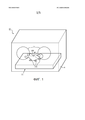
[7] ФИГ. 1 иллюстрирует систему мониторинга субъекта в соответствии с одним или несколькими вариантами реализации настоящего изобретения;[7] FIG. 1 illustrates a subject monitoring system in accordance with one or more embodiments of the present invention;
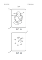
[8] ФИГУРЫ 2A-2B иллюстрируют систему в соответствии с одним или несколькими вариантами реализации настоящего изобретения; [8] FIGURES 2A-2B illustrate a system in accordance with one or more embodiments of the present invention;
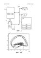
[9] ФИГ. 3 схематически иллюстрирует систему мониторинга субъекта в соответствии с одним или несколькими вариантами реализации настоящего изобретения;[9] FIG. 3 schematically illustrates a subject monitoring system in accordance with one or more embodiments of the present invention;
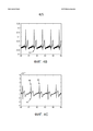
[10] ФИГУРЫ 4A-4B-4C иллюстрируют графики, отображающие измерения, выполненные в соответствии с одним или несколькими вариантами реализации настоящего изобретения; и[10] FIGURES 4A-4B-4C illustrate graphs depicting measurements taken in accordance with one or more embodiments of the present invention; and
[11] ФИГ. 5 иллюстрирует способ определения одного или более сигналов ЭКГ субъекта в соответствии с одним или несколькими вариантами реализации настоящего изобретения.[11] FIG. 5 illustrates a method for determining one or more ECG signals of a subject in accordance with one or more embodiments of the present invention.
ОСУЩЕСТВЛЕНИЕ ИЗОБРЕТЕНИЯDETAILED DESCRIPTION OF THE INVENTION
[12] В контексте настоящего документа единственное число включает множественное число, если явно не указано иное. В контексте настоящего документа утверждение, что две или большее количество деталей или компонентов «соединены», будет означать, что эти детали соединены или работают вместе прямо или непрямо, то есть, через одну или более промежуточных деталей или компонентов, пока это соединение существует. В контексте настоящего документа «прямо соединены» означает, что два элемента находятся в непосредственном контакте друг с другом. В контексте настоящего документа «неподвижно соединены» или «зафиксированы» означает, что два компонента соединены таким образом, что двигаются как одно целое при сохранении их пространственного расположения относительно друг друга.[12] In the context of this document, the singular includes the plural, unless expressly indicated otherwise. In the context of this document, the statement that two or more parts or components are “connected” will mean that these parts are connected or work together directly or indirectly, that is, through one or more intermediate parts or components, as long as this connection exists. In the context of this document, “directly connected” means that the two elements are in direct contact with each other. In the context of this document, “fixedly connected” or “fixed” means that the two components are connected in such a way that they move as a unit while maintaining their spatial arrangement relative to each other.
[13] В контексте настоящего документа слово «цельный» означает компонент, созданный как одна деталь или блок. То есть, компонент, включающий детали, которые были созданы отдельно и затем соединены вместе как блок, не является «цельным» компонентом или телом. В контексте настоящего документа утверждение, что две или большее количество деталей или компонентов «находятся в контакте» друг с другом, будет означать, что указанные детали прикладывают силу друг к другу непосредственно или через одну или большее количество промежуточных деталей или компонентов. В контексте настоящего документа термин «число» будет означать единицу или целое число больше единицы (то есть, множество).[13] In the context of this document, the word "integral" means a component created as a single part or block. That is, a component that includes parts that were created separately and then joined together as a unit is not a “solid” component or body. In the context of this document, the statement that two or more parts or components are “in contact” with each other will mean that these parts apply force to each other directly or through one or more intermediate parts or components. In the context of this document, the term "number" will mean a unit or an integer greater than one (that is, a plurality).
[14] Используемые в данном документе слова, указывающие направление, такие как, например, верх, низ, левый, правый, верхний, нижний, передний, задний и их производные, относятся к пространственному положению элементов, показанному на чертежах, и не ограничиваются содержанием формулы изобретения, если явно не изложено иное.[14] Used in this document, words indicating direction, such as, for example, top, bottom, left, right, top, bottom, front, rear and their derivatives, refer to the spatial position of the elements shown in the drawings, and are not limited to the content claims, unless expressly stated otherwise.
[15] ФИГ. 1 иллюстрирует систему 10 для (неинвазивного) мониторинга субъекта 106. Систему 10 можно также взаимозаменяемо называть как «система 10 мониторинга». Система 10 может включать один или больше следующих объектов: корпус 11 взаимодействия, кувез 4 с отверстиями 3 доступа, множество емкостных датчиков 143 и/или другие компоненты (включая компоненты, показанные на других ФИГУРАХ, на которых они включены в систему 10). Корпус 11 обеспечения взаимодействия можно также взаимозаменяемо называть как «конструкция обеспечения взаимодействия», «конструкция», «опорная конструкция обеспечения взаимодействия» или «опорная конструкция». В качестве неограничивающего примера, ФИГ. 3 схематически иллюстрирует систему 10a, которая может включать все компоненты и элементы, относящиеся к системе 10, описанные в других местах данного документа, и которая может дополнительно включать, как показано на ФИГ. 3, один или больше следующих объектов: электронное запоминающее устройство 130, пользовательский интерфейс 120, один или больше процессоров 110, один или больше компьютерных программных модулей и/или другие компоненты. На ФИГ. 3 компьютерные программные модули могут включать один или больше модулей 111 соединения, модуль 112 выбора, модуль 113 реконструкции и/или другие модули. Также на ФИГ. 3 в качестве неограничивающего примера показан пользователь 108 системы 10, такой как лицо, осуществляющее уход, лицо, ответственное за лечение, и/или медицинский специалист.[15] FIG. 1 illustrates a
[16] Неинвазивное, малозаметное и/или устойчивое к движениям определение сердечной деятельности субъекта, включая электрокардиографию (ЭКГ), в частности новорожденных и/или младенцев, может помогать получать с медицинской и/или диагностической точки зрения релевантную информацию без нарушения, стресса, боли и/или дискомфорта, связанных с инвазивными процедурами. Методики, описанные в этом документе, могут применяться как к людям, так и к животным. Изменения во времени таких контролируемых параметров могут быть особенно важными. В контексте настоящего документа термин «неинвазивный» может относиться к отсутствию клеящих веществ для фиксации на месте датчиков и/или отсутствию физических устройств, которые проникают внутрь кожи или прилипают к ней, или каким-либо образом вставляются в тело субъекта. Приклеивающиеся датчики могут повредить (очень тонкую) кожу и при использовании могут вызывать стрессовое состояние, чувство дискомфорта и/или боль. В контексте настоящего документа термин «устойчивый к движениям» может относиться к способности выполнять надежные измерения при наличии ограниченного движения субъекта 106. Ползание, движения рук, ног и головы, переворачивание с боку на бок, изменения положения тела, движения, когда субъект волнуется или плохо себя чувствует, и другие подобные движения можно определить как ограниченные движения. В некоторых вариантах реализации уход за субъектом 106 по месту и/или на месте, включая, в частности, кормление, замену памперсов или пеленок, взятие тест-анализов и/или другие действия, которые обычно выполняются при уходе или медицинском уходе новорожденных и/или младенцев, могут быть определены как ограниченные движения, пока субъект 106 остается в пределах заданного расстояния от емкостных датчиков 143. Такое заданное расстояние может быть расстоянием от отдельного конкретного емкостного датчика, от всех емкостных датчиков, используемых в конкретном варианте реализации, средним расстоянием для множества емкостных датчиков и/или каким-либо другим образом заданным расстоянием для конкретного варианта реализации. Измерения, выполненные в то время, когда субъект 106 находится от емкостных датчиков 143 на расстоянии, которое больше заданного расстояния, не может быть отнесено к измерениям, выполненным при ограниченном движении, независимо от фактического движения субъекта 106. Предполагается, что медицинские условия и/или вопросы, упомянутые в этом описании, являются типовыми и неограничивающими.[16] A non-invasive, subtle, and / or motion-resistant determination of the subject's cardiac activity, including electrocardiography (ECG), in particular of newborns and / or infants, can help to obtain relevant information from a medical and / or diagnostic point of view without disturbance, stress, pain and / or discomfort associated with invasive procedures. The techniques described in this document can be applied to both humans and animals. Time variations of such monitored parameters can be especially important. In the context of this document, the term "non-invasive" may refer to the absence of adhesives for fixing in place of the sensors and / or the absence of physical devices that penetrate the skin or adhere to it, or are somehow inserted into the body of the subject. Adhesive sensors can damage (very thin) skin and can cause stress, discomfort and / or pain when used. In the context of this document, the term “motion resistant” may refer to the ability to perform reliable measurements in the presence of limited movement of the
[17] На ФИГ. 1 корпус 11 обеспечения взаимодействия выполнен с возможностью контактировать с субъектом 106, например с новорожденным и/или с младенцем. В некоторых вариантах реализации корпус 11 обеспечения взаимодействия может быть реализован как опорная конструкция (для субъекта), выполненная с возможностью поддерживать субъекта 106. Опорная конструкция для субъекта может быть матрасом, кроватью, подкладкой, одеялом, платком, подушкой, кувезом и/или другой конструкцией, подходящим для взаимодействия с субъектом 106 и/или его поддержки. В некоторых вариантах реализации корпус 11 обеспечения взаимодействия может быть предметом одежды, выполненным с возможностью носки субъекта 106 и/или оборачивания вокруг него. Корпус 11 обеспечения взаимодействия может быть выполнен с возможностью нести один или больше датчиков, например один или больше емкостных датчиков 143. На ФИГУРАХ 2A и 2B в качестве иллюстрации показан вид сверху системы 10, включающей корпус 11 обеспечения взаимодействия и множество емкостных датчиков 143. На ФИГ. 2A субъект 106 расположен сверху на корпусе 11 обеспечения взаимодействия, нарушая, таким образом, прямую видимость некоторых емкостных датчиков 143, которые показаны штриховыми линиями на ФИГ. 2A. ФИГ. 2B иллюстрирует ту же систему 10 и тот же корпус обеспечения взаимодействия, что показаны на ФИГ. 2A, но без субъекта 106, закрывающего часть поля зрения. На фигуре показано только иллюстративное количество емкостных датчиков 143, и не предполагается их ограничение каким-либо образом. Образец расположения и/или компоновка емкостных датчиков 143, показанные на ФИГ. 2B, например, напоминающие цветочные лепестки, являются только иллюстративными и не могут считаться ограничивающими каким-либо образом.[17] FIG. 1, the
[18] В контексте настоящего документа при общем упоминании емкостного датчика или множества емкостных датчиков могут использоваться термины «емкостный датчик 143» или «емкостный датчик(и) 143» или их производные, и везде будет использоваться номер позиции «143», а при упоминании отдельного конкретного емкостного датчика к указанному номеру позиции может быть добавлена буква, например «емкостный датчик 143a» или «емкостный датчик 143b», как показано на ФИГ. 2B. Данное описание не ограничено количеством или положением датчиков, показанных на какой-либо из фигур. В контексте настоящего документа термин «измерять» относится к любой комбинации процессов измерения, оценки и/или приблизительного подсчета исходя из выходного сигнала, выработанного одним или более датчиками. В контексте настоящего документа термин «измерение» относится к любой комбинации одного или более измерений, оценок, определений, заключений и/или приблизительных подсчетов исходя из выходного сигнала, выработанного одним или более датчиками.[18] In the context of this document, when referring to a capacitive sensor or a plurality of capacitive sensors, the terms “
[19] Емкостный датчик(и) 143 может быть выполнен с возможностью вырабатывать выходные сигналы, передающие информацию одного или более типов, которая обобщенно называется информацией датчиков. В частности, емкостный датчик(и) 143 может быть выполнен с возможностью вырабатывать выходные сигналы, передающие электрофизиологическую информацию о субъекте 106, и/или выходные сигналы, передающие информацию, связанную предсказуемым способом (например, с помощью математических соотношений) с электрофизиологическими параметрами субъекта 106, которую обобщенно можно назвать электрофизиологической информацией. Информация датчиков может включать электрофизиологическую информацию. Емкостные датчики могут успешно образовывать конденсатор, в котором кожа субъекта 106 работает как одна пластина, а электрод емкостного датчика работает как вторая пластина. Корпус 11 обеспечения взаимодействия может поддерживать и/или нести емкостный датчик(и) 143. [19] Capacitive sensor (s) 143 may be configured to generate output signals transmitting information of one or more types, which is collectively referred to as sensor information. In particular, the capacitive sensor (s) 143 may be configured to generate output signals transmitting electrophysiological information about the subject 106 and / or output signals transmitting information associated in a predictable manner (for example, using mathematical relationships) with the electrophysiological parameters of the subject 106 , which generally can be called electrophysiological information. Sensor information may include electrophysiological information. Capacitive sensors can successfully form a capacitor in which the skin of the subject 106 operates as a single plate, and the capacitive sensor electrode works as a second plate. The
[20] В некоторых вариантах реализации емкостный датчик(и) 143 может быть выполнен с возможностью вырабатывать выходные сигналы, передающие электрическую и/или другую информацию о связи между двумя объектами (например, между самим датчиком и субъектом 106). В некоторых вариантах реализации информация датчиков может включать информацию о связи и/или электрофизиологическую информацию. [20] In some embodiments, the capacitive sensor (s) 143 may be configured to generate output signals transmitting electrical and / or other communication information between two objects (for example, between the sensor itself and subject 106). In some embodiments, the sensor information may include communication information and / or electrophysiological information.
[21] В некоторых вариантах реализации информация о связи может быть передана посредством интенсивности, мощности, амплитуды, спектральной информации, фазового сдвига и/или уровня сигнала, выработанного емкостным датчиком(ами) 143. Например, рассматривая ФИГ. 2A, в некоторых вариантах реализации отдельный емкостный датчик 143a может испускать сигнал (например, электромагнитный сигнал), имеющий одну или больше известных характеристик (включая, в том числе, известные частоту, фазу, форму, амплитуду и/или другую характеристику электромагнитного сигнала). Такой испускаемый сигнал может быть назван несущим сигналом. Информация о связи для отдельного емкостного датчика 143a может быть определена и/или основана на том, насколько хорошо испускаемый сигнал принимается отдельным емкостным датчиком 143a. Информация датчиков может включать по меньшей мере компонент, который соответствует несущему сигналу и/или отображает несущий сигнал, и этот компонент может использоваться для определения информации о связи и/или в качестве основания для такого определения. В некоторых вариантах реализации информация датчиков может включать модулированный несущий сигнал (и/или модулированный вариант несущего сигнала), то есть вариант несущего сигнала, который был промодулирован и/или на который оказала воздействие емкостная связь между емкостным датчиком 143 и субъектом (кожей) 106.[21] In some embodiments, the communication information may be transmitted by means of intensity, power, amplitude, spectral information, phase shift and / or signal level generated by the capacitive sensor (s) 143. For example, by considering FIG. 2A, in some embodiments, a
[22] В контексте настоящего документа не предполагается ограничение термина «емкостный датчик» конструкциями для приема и/или измерения сигналов, и он может включать конструкции для передачи, испускания, пересылки, транслирования, выработки и/или создания сигналов. Такие «емкостные датчики» на равных основаниях можно назвать «емкостными приемопередатчиками» и их производными. В случае хорошей и/или сильной связи между емкостным датчиком 143a и субъектом 106 полученный сигнал (например, часть или компонент информации датчиков, который соответствует несущему сигналу) может иметь, например, большую амплитуду, чем в случае плохой и/или слабой связи между емкостным датчиком 143a и субъектом 106. [22] In the context of this document, the term “capacitive sensor” is not intended to be limited to structures for receiving and / or measuring signals, and may include structures for transmitting, emitting, forwarding, broadcasting, generating and / or generating signals. Such "capacitive sensors" on an equal footing can be called "capacitive transceivers" and their derivatives. In the case of a good and / or strong connection between the
[23] В некоторых вариантах реализации часть или компонент информации датчиков, который соответствует испускаемому несущему сигналу (и/или отображает испускаемый несущий сигнал), можно отличить от части или компонента информации датчиков, передающего электрофизиологическую информацию, посредством различения (электромагнитных) характеристик, включая, в том числе, частоту, фазу, форму, амплитуду и/или другие характеристики электромагнитного сигнала. Например, электрофизиологическая информация может быть (биологически) ограничена (заданным) диапазоном частот и/или другими характеристиками. Емкостные датчики 143 могут быть выполнены с возможностью испускать несущий сигнал. В некоторых вариантах реализации испускаемый несущий сигнал может иметь характеристику, выходящую за пределы ограниченного диапазона. Например, несущие сигналы, испускаемые емкостными датчиками 143, могут иметь одну или несколько более высоких частот (например, около 1 кГц, около 10 кГц, около 100 кГц, около 1 МГц и/или другие применимые частоты), чем частоты диапазона электрофизиологической информации (например, ниже 1 кГц и/или ниже/выше применимой частоты, выбранной и/или отобранной для емкостных датчиков 143). Система 10 может отличить электрофизиологическую информацию от информации о связи в информации датчиков посредством фильтрации и/или использования методик обработки сигналов, подходящих для выбранного и/или отобранного отличительного признака(ов), описанного в данном документе. Кроме использования несущих сигналов для выбора канала, что объяснено в другом месте этого описания, несущие сигналы могут использоваться для реконструкции сигнала электрокардиограммы (ЭКГ). [23] In some embodiments, a portion or component of sensor information that corresponds to an emitted carrier signal (and / or displays an emitted carrier signal) can be distinguished from a part or component of sensor information transmitting electrophysiological information by distinguishing between (electromagnetic) characteristics, including, including frequency, phase, shape, amplitude and / or other characteristics of the electromagnetic signal. For example, electrophysiological information may be (biologically) limited by a (predetermined) frequency range and / or other characteristics.
[24] В некоторых вариантах реализации система 10 может включать 3, 4, 5, 6, 7, 8 или большее количество емкостных датчиков 143. На ФИГ. 2B для наглядности показан типовой вариант реализации системы 10, которая включает 8 емкостных датчиков 143. Системы, в которых используются один или два емкостных датчика 143, не могут быть устойчивыми к движениям и/или будут не в состоянии обеспечивать надежные измерения в различных положениях тела, включая, в том числе, в положениях на спине, на животе и/или на боку.[24] In some embodiments, the
[25] Датчики в этом описании могут быть выполнены с возможностью постоянно вырабатывать выходные сигналы, например, на протяжении всего дня. Этот процесс может включать вырабатывание сигналов с перерывами, периодически (например, с частотой выборки), постоянно, непрерывно, с изменяющимися интервалами и/или другим способом, которое длится на протяжении по меньшей мере части дня, недели, месяца или интервала другой длительности. Частота выборки может составлять около 0,001 секунды, 0,01 секунды, 0,1 секунды, 1 секунду, около 10 секунд, около 1 минуты и/или другое значение. Следует отметить, что множество отдельных датчиков могут работать с разными частотами выборки в зависимости от конкретных выходных сигналов (частот, связанных с конкретными выходными сигналами) и/или полученных из них параметров. Например, в некоторых вариантах реализации выработанные выходные сигналы могут рассматриваться как вектор выходных сигналов, так что такой вектор включает множество образцов переданной информации, связанной с одним или более параметрами субъекта 106. Разные параметры могут быть связаны с разными векторами. Конкретный параметр, определенный постоянно действующим способом из вектора выходных сигналов, может рассматриваться как вектор этого конкретного параметра.[25] The sensors in this description can be configured to continuously generate output signals, for example, throughout the day. This process may include generating signals intermittently, periodically (for example, with a sampling frequency), continuously, continuously, at varying intervals and / or in another way, which lasts for at least part of a day, week, month or interval of another duration. The sampling rate may be about 0.001 seconds, 0.01 seconds, 0.1 seconds, 1 second, about 10 seconds, about 1 minute, and / or another value. It should be noted that many individual sensors can operate with different sampling frequencies depending on specific output signals (frequencies associated with specific output signals) and / or parameters obtained from them. For example, in some implementations, the generated output signals can be considered as a vector of output signals, so that such a vector includes many samples of transmitted information associated with one or more parameters of the subject 106. Different parameters can be associated with different vectors. A specific parameter determined by a permanent method from the vector of output signals can be considered as a vector of this specific parameter.
[26] Система 10 на ФИГ. 3 (и/или система 10a, которая равноценно используется на ФИГ. 3) может включать электронное запоминающее устройство 130, содержащее электронный носитель информации, который хранит информацию в электронном виде. Такой электронный носитель информации электронного запоминающего устройства 130 включает одно или два запоминающих устройства системы, которые встроены (то есть являются по существу несъемными) в систему 10, и/или съемное запоминающее устройство, которое соединяется с системой 10, например, через порт (например, USB-порт, порт шины FireWire и т.д.) или через привод (например, дисковод и т.д.). Электронное запоминающее устройство 130 может включать один или больше следующих объектов: оптически считываемые носители информации (например, оптические диски и т.д.), магнитным способом считываемые носители информации (например, магнитная лента, магнитный жесткий диск, накопитель на гибких магнитных дисках и т.д.), носители информации на основе электрического заряда (например, EEPROM, ОЗУ и т.д.), твердотельные носители информации (например, карта флэш-памяти и т.д.) и/или другие электронным способом считываемые носители информации. Электронное запоминающее устройство 130 хранит программно-реализованные алгоритмы, информацию, установленную процессором 110, информацию, полученную через пользовательский интерфейс 120, и/или другую информацию, которая позволяет системе 10 надлежащим образом функционировать. Например, электронное запоминающее устройство 130 может записывать или хранить один или более (ряд) параметров, полученных из выходных сигналов, измеренных (например, в течение некоторого времени) одним или более датчиками (что обсуждается в другом месте данного документа), и/или другую информацию. Электронное запоминающее устройство 130 может быть отдельным компонентом внутри системы 10, или электронное запоминающее устройство 130 может образовывать единое целое с одним или несколькими другими компонентами системы 10 (например, с процессором 110).[26] The
[27] Система 10 на ФИГ. 3 10 может включать пользовательский интерфейс 120, выполненный с возможностью обеспечивать интерфейс между системой 10 и пользователем (например, пользователем 108, лицом, осуществляющим уход, лицом, ответственным за лечение, и т.д.), с помощью которого пользователь может передавать информацию системе 10 и получать информацию от нее. Это позволяет выполнять обмен данными, результатами и/или указаниями и любыми другими передаваемыми элементами, которые обобщенно называются «информацией», между пользователем и системой 10. Примеры интерфейсных устройств, пригодных для включения в пользовательский интерфейс 120, включают клавишную панель, кнопки, переключатели, клавиатуру, круглые кнопки, рычаги, экран дисплея, сенсорный экран, динамики, микрофон, световые индикаторы, звуковую сигнализацию и принтер. Информация может передаваться пользователю 108 пользовательским интерфейсом 120, например, в виде звуковых сигналов, визуальных сигналов, осязательных сигналов и/или других сигналов датчика. [27] The
[28] В качестве неограничивающего примера в некоторых вариантах реализации пользовательский интерфейс 120 включает источник излучения, способный испускать свет. Такой источник излучения включает один или больше следующих объектов: СИД, лампа накаливания, экран дисплея, и/или другие источники. Пользовательский интерфейс 120 может управлять испусканием света источником излучения способом, который позволяет передавать информацию, например, пользователю 108, связанную, например, с выходом за заданное пороговое значение частоты сердечных сокращений у субъекта 106.[28] As a non-limiting example, in some embodiments, the
[29] Следует понимать, что и другие технологии связи, как проводные, так и беспроводные, также рассмотрены в данном документе в качестве пользовательского интерфейса 120. Например, в одном варианте реализации пользовательский интерфейс 120 выполнен как одно целое со съемным интерфейсом хранения, обеспечиваемым электронным запоминающим устройством 130. В этом примере информация загружается в систему 10 со съемного запоминающего устройства (например, со смарт-карты, карты флэш-памяти, съемного диска и т.д.), что позволяет пользователю(ям) адаптировать реализацию системы 10 к своим требованиям. Другие типовые устройства и технологии ввода данных, адаптированные для использования с системой 10 в качестве пользовательского интерфейса 120, включают, в частности, порт RS-232, радиочастотный канал передачи данных, инфракрасный канал передачи данных, модем (телефон, кабель, сеть Ethernet, сеть Интернет и т.д.). Одним словом, любая технология обмена информацией с системой 10 рассматривается в качестве пользовательского интерфейса 120.[29] It should be understood that other communication technologies, both wired and wireless, are also discussed herein as
[30] На ФИГ. 3 процессор 110 выполнен с возможностью обеспечивать способность системы 10 обрабатывать информацию. В силу этого, процессор 110 включает один или больше следующих объектов: цифровой процессор, аналоговый процессор, цифровая схема, разработанная для обработки информации, аналоговая схема, разработанная для обработки информации, и/или другие устройства электронной обработки информации. Хотя процессор 110 показан на ФИГ. 3 как единое целое, такой вариант показан только с иллюстративной целью. В некоторых вариантах реализации процессор 110 включает множество блоков обработки. [30] FIG. 3,
[31] Как показано на ФИГ. 3, процессор 110 выполнен с возможностью реализовывать один или более компьютерных программных модулей. Один или более компьютерных программных модулей включают один или более следующих объектов: модуль 111 соединения, модуль 112 выбора, модуль 113 реконструкции и/или других модулей. Процессор 110 может быть выполнен с возможностью реализовывать модули 111-113 с помощью программного обеспечения, аппаратных средств, встроенного программного обеспечения, некоторой комбинации программного обеспечения, аппаратных средств и/или встроенного программного обеспечения и/или других механизмов конфигурирования способности обработки данных процессором 110, включая программируемое аппаратное обеспечение. [31] As shown in FIG. 3, the
[32] Следует понимать, что хотя модули 111-113 показаны на ФИГ. 3 как расположенные внутри единого блока обработки, в вариантах реализации, в которых процессор 110 включает несколько блоков обработки, один или более модулей 111-113 могут быть расположены удаленно от других модулей. Описание функциональных возможностей, обеспечиваемых разными модулями 111-113, представлено ниже с иллюстративной целью, и не предполагается в качестве ограничивающего, поскольку любой из модулей 111-113 может обеспечить большие или меньшие функциональные возможности по сравнению с описанными. Например, один или более модулей 111-113 могут быть исключены, а некоторые или все их функциональные возможности могут быть обеспечены другими модулями 111-113. Примите во внимание, что процессор 110 может быть выполнен с возможностью реализовывать один или несколько дополнительных модулей, которые могут обеспечивать некоторые или все функциональные возможности, которыми обладает один из описанных ниже модулей 111-113.[32] It should be understood that although modules 111-113 are shown in FIG. 3 as located within a single processing unit, in embodiments in which the
[33] Модуль 111 соединения системы 10 на ФИГ. 3 выполнен с возможностью определять уровни соединения для одного или большего количества емкостных датчиков 143 системы 10. В контексте настоящего документа термин «уровень соединения» может относиться к силе соединения (например, электрических сигналов), и/или мощности сигнала (например, электрических сигналов). В некоторых вариантах реализации уровни соединения могут быть основаны на интенсивности, амплитуде, мощности, магнитуде, содержании энергии, емкостных уровнях, спектральной информации, фазовом сдвиге и/или других типах уровней и/или комбинациях указанных характеристик, которые могут указывать, следует ли считать надежным (и/или в какой степени) выходной сигнал емкостного датчика 143. Поочередно и/или одновременно, в некоторых вариантах реализации уровень соединения может указывать, следует ли исключить выходной сигнал емкостного датчика 143, например, в пользу более мощных и/или более надежных сигналов других емкостных датчиков 143. Определение уровней соединения модулем 111 соединения может быть основано на всем выходном сигнале (например, на всей информации датчиков) или на одной или большем количестве его частях или компонентах (например, на одной или большем количестве частей или компонентов, которые соответствуют информации о связи). Например, в некоторых вариантах реализации уровень соединения для конкретного емкостного датчика 143a может быть основан на амплитуде части выходного сигнала, которая попадает в конкретный диапазон частот, например, выше 1 кГц. Часть выходного сигнала, которая попала в конкретный диапазон частот, соответствует информации о связи. В некоторых вариантах реализации уровень соединения может быть основан на характеристике всего выходного сигнал, а не его части.[33]
[34] Уровень соединения для отдельного емкостного датчика 143 может изменяться на протяжении некоторого периода времени, например, между отдельными измерениями. Изменения уровней соединения на протяжении некоторого периода времени могут быть вызваны, например, движением субъекта 106. Модуль 111 соединения может быть выполнен с возможностью располагать в некотором порядке, устанавливать по ранжиру и/или каким-либо другим способом сравнивать уровни соединения емкостного датчика 143 с уровнями соединения одного или большего количества других емкостных датчиков 143. Модуль 111 соединения может быть выполнен с возможностью определять уровни соединения для некоторых или для всех емкостных датчиков 143 с одной и той же или близкой частотой выборки таким образом, что изменение уровней соединения может быть повторно оценено с одной и той же или близкой частотой выборки для определения того, использовать или отбрасывать соответствующие измерения емкостных датчиков 143.[34] The connection level for an
[35] В некоторых вариантах реализации модуль 111 соединения может быть выполнен с возможностью определять, какой именно емкостный датчик 143 из набора емкостных датчиков 143 имеет наивысший и/или самый мощный уровень соединения. Этот конкретный емкостный датчик 143 может быть назван максимальным емкостным датчиком. Максимальный емкостный датчик может изменяться от одного конкретного емкостного датчика 143a к другому конкретному емкостному датчику 143b, например, после измерений, выполненных обоими емкостными датчиками. Уровень соединения максимального емкостного датчика может быть назван максимальным уровнем соединения. В некоторых вариантах реализации модуль 111 соединения может быть выполнен с возможностью определять обобщенный уровень соединения для одного или большего количества емкостных датчиков 143. Например, обобщенный уровень соединения может быть основан на одном или большем количестве следующих параметров: среднее значение, математическое ожидание, среднеквадратичное отклонение, дисперсия, и/или других статистических и/или обобщенных функциях, которые дают одно выходное значение для множества уровней соединения. Уровни соединения, используемые для определения обобщенного уровня соединения, могут включать уровни соединения всех установленных емкостных датчиков 143, всех установленных емкостных датчиков, за исключением максимального емкостного датчика, всех установленных емкостных датчиков 143, имеющих уровень соединения, по меньшей мере достаточно высокий или мощный для пересечения минимального порогового значения соединения, всех установленных емкостных датчиков, за исключением максимального датчика, имеющих уровень соединения, по меньшей мере достаточно высокий или мощный для пересечения минимального порогового значения соединения, и/или другие поднаборы емкостных датчиков 143, которые могут быть повторно оценены после выполнения измерений, например, с данной частотой выборки.[35] In some embodiments, the
[36] Модуль 112 выбора системы 10 на ФИГ. 3 выполнен с возможностью выбора одного или большего количества емкостных датчиков 143. Модуль 112 выбора может выполнять многократный последовательный выбор для исключения одного или большего количества емкостных датчиков 143. Выходные сигналы одного или большего количества выбранных емкостных датчиков могут использоваться, например, модулем 113 реконструкции для определения сигнала и/или параметра электрокардиограммы (ЭКГ). Выбор модулем 112 выбора может быть основан на уровнях соединения, определенных модулем 111 соединения. В некоторых вариантах реализации уровни соединения ниже минимального порогового значения соединения могут быть автоматически исключены из выбора. В некоторых вариантах реализации уровни соединения выше надлежащего порогового значения соединения могут быть автоматически включены в выбор. В некоторых вариантах реализации минимальное пороговое значение соединения может быть абсолютным значением. В некоторых вариантах реализации минимальное пороговое значение соединения может зависеть и/или основываться на максимальном уровне соединения, на обобщенном уровне соединения или на обоих указанных уровнях исходя из поднабора значений уровней соединения соответствующих поднаборов емкостных датчиков. В некоторых вариантах реализации надлежащее пороговое значение соединения может быть абсолютным значением. В некоторых вариантах реализации надлежащее пороговое значение соединения может зависеть и/или основываться на максимальном уровне соединения, на обобщенном уровне соединения или на обоих указанных уровнях исходя из поднабора значений уровней соединения соответствующих поднаборов емкостных датчиков.[36] The
[37] Например, в некоторых вариантах реализации выбор модулем 112 выбора может быть основан на сравнениях между максимальным уровнем соединения (например, выходного сигнала, имеющего максимальную амплитуду, для (по существу) всей информации датчиков или для максимального содержания энергии для диапазона частот, соответствующего информации о связи) и уровнями соединения для других (не максимальных) датчиков соединения. Такие сравнения могут быть основаны на соотношениях, дисперсиях и/или другой арифметической и/или статистической обработке данных уровней соединения. Например, дисперсию максимального уровня соединения можно сравнить с дисперсиями одного или нескольких других уровней соединения для выполнения выбора модулем 112 выбора. Термин «по существу вся информация датчиков» может быть интерпретирован как информация датчиков, включающая всю или большую часть электрофизиологической информации и включающая всю или большую часть информации о связи. В некоторых вариантах реализации информация датчиков может быть обработана перед использованием модулем 112 выбора, как описано в данном документе. Например, компоненты сигнала, имеющие частоту ниже нижнего порогового значения частоты, могут быть исключены. Нижнее пороговое значение частоты может составлять 20 Гц, 15 Гц, 10 Гц, 5 Гц, 4 Гц, 3 Гц, 2 Гц, 1 Гц и/или иметь другое подходящее нижнее пороговое значение частоты. Такая обработанная информация датчиков может быть названа как «по существу вся информация датчиков».[37] For example, in some embodiments, the selection by the
[38] В некоторых вариантах реализации выбор модулем 112 выбора может быть основан на одном или большем количестве коэффициентов корреляции, например, путем их сравнения. Можно определить коэффициент корреляции между выходными сигналами двух емкостных датчиков 143 и/или между двумя соответствующими уровнями соединения. Коэффициенты корреляции могут включать один или более следующих объектов: коэффициента корреляции Пирсона, коэффициента ранговой корреляции и/или другие виды статистической корреляции. Полагая, что максимальный емкостный датчик был определен, можно определить первый коэффициент корреляции между соответствующим максимальным уровнем соединения и уровнем соединения первого конкретного емкостного датчика 143a. Второй коэффициент корреляции может быть определен между максимальным уровнем соединения и уровнем соединения второго конкретного емкостного датчика 143b, и так далее – для дополнительных уровней соединения других (возможно, предварительно выбранных на основании других критериев, что описано в другом месте данного документа) емкостных датчиков. Выбор модулем 112 выбора может быть основан на сравнении первого коэффициента корреляции, второго коэффициента корреляции и т.д. Например, модуль 112 выбора может исключить выходные сигналы емкостных датчиков с коэффициентами корреляции (с максимальным уровнем соединения) ниже минимального порогового значения корреляции.[38] In some embodiments, the selection by the
[39] В некоторых вариантах реализации выбор модулем 112 выбора может быть основан на определении количества информации, содержащейся в выходных сигналах конкретных емкостных датчиков. Количество информации может быть определено в абсолютном выражении или относительно выходных сигналов максимального датчика. Например, если два емкостных датчика, первый и второй емкостные датчики, выработали одинаковые или очень похожие выходные сигналы, дополнительное количество информации, добавленное вторым емкостным датчиком к информации, предоставленной первым емкостным датчиком, может быть небольшим и/или ограниченным и может послужить основанием для исключения второго емкостного датчика из выбора модуля 112 выбора. [39] In some embodiments, the selection by the
[40] В некоторых вариантах реализации выбор модулем 112 выбора может быть основан на пространственном распределении множества емкостных датчиков 143. Пространственное распределение может быть использовано с целью отдать при выборе предпочтение емкостным датчикам 143, охватывающим наибольшую площадь корпуса 11 обеспечения взаимодействия. В некоторых вариантах реализации набор емкостных датчиков 143 соответствует взвешенной матрице. Выбор модулем 112 выбора может быть реализован посредством корректировки и/или подстройки весов во взвешенной матрице. В некоторых вариантах реализации пространственное распределение может стать причиной наложения штрафных санкций вследствие близкого расположения. Например, если первый и второй емкостные датчики имеют похожие уровни соединения согласно одному и тому же определению (например, по сравнению с максимальным емкостным датчиком), принимая во внимание пространственное распределение, первому емкостному датчику может быть отдано предпочтение по сравнению с вторым емкостным датчиком, поскольку он (первый датчик) дальше находится от максимального емкостного датчика. При этом, на второй емкостный датчик может быть наложена штрафная санкция (например, путем снижения его весового коэффициента во взвешенной матрице), так как он находится ближе к максимальному емкостному датчику. В некоторых вариантах реализации пространственное распределение может использоваться только при по меньшей мере минимальном количестве емкостных датчиков 143, имеющих по меньшей мере минимальный уровень соединения, и/или в ответ на другие условия.[40] In some embodiments, the selection by the
[41] Модуль 112 выбора может быть выполнен с возможностью выполнять несколько выборов, например, включая первый выбор, второй выбор и т.д. Несколько выборов могут быть определены и/или выполнены последовательно и/или одновременно. Выборы могут работать как фильтр, с помощью которого, как предполагается, емкостные датчики будут предоставлять надежную и/или полезную информацию. Например, первый выбор может быть основан на амплитуде уровней соединения набора емкостных датчиков 143 (как описано в другом месте данного документа), благодаря чему определяется первый поднабор емкостных датчиков 143 и исключается информация емкостных датчиков, не входящих в первый поднабор. Выбор такого поднабора может быть назван как «соответствие» или «прохождение» выбора. Второй выбор может быть основан на сравнениях коэффициентов корреляции между максимальным уровнем соединения и уровнями соединения емкостных датчиков в первом поднаборе. Исходя из второго выбора, определяется второй поднабор, который образует поднабор первого поднабора, вследствие чего исключается информация емкостных датчиков 143, не входящих во второй поднабор. Модуль 112 выбора не ограничен выполнением первого и второй выборов, а скорее может быть выполнен с возможностью выполнять набор двух, трех или большего количества выборов, которые могут быть последовательно применены для выполнения итерационного исключения отдельных емкостных датчиков (и соответствующей информации датчиков) до тех пор, пока не будет определен окончательный поднабор выбранных емкостных датчиков, включающий только те емкостные датчики, которые соответствуют и/или прошли все выполненные выборы.[41] The
[42] Модуль 113 реконструкции системы 10 на ФИГ. 3 выполнен с возможностью устанавливать сигнал электрокардиограммы (ЭКГ). Такое установление модулем 113 реконструкции может быть основано на выходных сигналах, выработанных одним или несколькими емкостными датчиками 143. В некоторых вариантах реализации установление модулем 113 реконструкции может быть основано на выходных сигналах поднабора выбранных емкостных датчиков, например, выбранных модулем 112 выбора. Работа модуля 113 реконструкции может быть основана на методиках, описанных в патенте США № 8 332 021, поданного Vullings с соавт. 20 января 2010 года и озаглавленного «Кардиотокография». Поочередно и/или одновременно, работа модуля 113 реконструкции может быть основана на методах слепого разделения сигналов, методах сравнения с эталонами и/или другими методами, которые могут использоваться для реконструкции электрокардиограммы (ЭКГ), такими как методики, основанные на использовании испускаемого несущего сигнала. Типовые виды работ, выполненных модулем 113 реконструкции, могут включать один или более следующих примеров: использование фильтра низких частот для по меньшей мере удаления одного или более сигналов шума в диапазоне от (приблизительно) 50 Гц до (приблизительно) 60 Гц, вызванных работой внешних электрических устройств, определение вектор-кардиограммы (ВКГ, показана на ФИГ. 4A) на основе выходных сигналов выбранных емкостных датчиков, приближенное представление эллипсом вектор-кардиограммы (ВКГ) для нескольких перекрывающихся сокращений сердца (смотрите ФИГ. 4A) и построение проекции вектор-кардиограммы (ВКГ) на длинную ось эллипса, или, в другом варианте, построение другой проекции, пригодной для максимального выявления R-пика на восстановленном сигнале электрокардиограммы (ЭКГ), что вытекает из этой проекции. [42] The
[43] Дополнительные этапы работы модуля 113 реконструкции могут включать выявление R-пика на восстановленном сигнале, применение фильтрации Калмана с использованием выявленных R-пиков и/или пересчет сигнала вектор-кардиограммы (ВКГ) из отфильтрованного фильтром Калмана сигнала и построение проекции этого ВКГ-сигнала для стандартных отведений Эйнтховена, что может широко использоваться в стандартном анализе ЭКГ. Фильтрация Кальмана может быть реализована путем определения максимума байесовской решающей функции последовательной оценки ЭКГ и путем применения пространственной корреляции между несколькими одновременно записанными сигналами ЭКГ. Полученная таким образом ковариационная оценка шума может использоваться в фильтрации Кальмана для присвоения и/или приписывания большего веса самой последней полученной информации датчиков, если эта информация датчиков содержит морфологическую вариативность, или для присвоения и/или приписывания меньшего веса, если морфологическая вариативность отсутствует или является незначительной.[43] Additional steps of the
[44] ФИГ. 4B иллюстрирует для наглядности стандартный сигнал 42 ЭКГ, отображающий несколько сокращений сердца, который может быть выработан с помощью общепринятых методик. По оси X отложено время, по оси Y – амплитуда в Вольтах. ФИГ. 4A иллюстрирует сигнал 41 вектор-кардиограммы (ВКГ), определенный на основе выходных сигналов 7 емкостных датчиков, измеренных во время испытаний. Оси X и Y отображают расстояния на плоскости, на которых расположены емкостные датчики. На ФИГ. 4A показаны несколько перекрывающихся сокращений сердца. ФИГ. 4C иллюстрирует восстановленный сигнал 43 ЭКГ на основе определенного сигнала 41 ВКГ на ФИГ. 4A. Восстановленный сигнал 43 ЭКГ 43 хорошо соответствует стандартному сигналу 42 ЭКГ. R-пики 44 отчетливо выявлены и/или показаны на восстановленном сигнале 43 ЭКГ.[44] FIG. 4B illustrates for illustrative purposes the
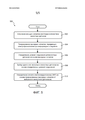
[45] ФИГ. 5 иллюстрирует способ 500 выполнения электрокардиографического (ЭКГ) мониторинга субъекта 106. Операции способа 500 представлены ниже только с иллюстративной целью. В некоторых вариантах реализации способ 500 может выполняться с одной или с несколькими дополнительными операциями, которые не описаны, и/или без одной или более операций, которые здесь обсуждаются. Кроме того, предполагается, что порядок выполнения операций способа 500, показанный на ФИГ. 5 и описанный ниже, не является ограничивающим.[45] FIG. 5 illustrates a
[46] В некоторых вариантах реализации способ 500 может быть реализован в одном или более устройствах обработки (например, в цифровом процессоре, аналоговом процессоре, цифровой схеме, разработанной для обработки информации, аналоговой схеме, разработанной для обработки информации, и/или в других устройствах электронной обработки информации). Одно или несколько устройств обработки могут включать одно или несколько устройств, выполняющих несколько или все операции способа 500 в ответ на команды, хранящиеся в электронном виде в электронном запоминающем устройстве. Одно или несколько устройств обработки могут включать одно или несколько устройств, которые оборудованы аппаратными средствами, встроенным программным обеспечением и/или программным обеспечением и специально разработаны для выполнения одной или более операций способа 500.[46] In some embodiments, the
[47] В операции 502 множество емкостных датчиков испускают несущие сигналы вблизи субъекта. В некоторых вариантах реализации операция 502 выполняется емкостными датчиками, которые являются такими же или подобными емкостным датчикам 143 (показаны на ФИГУРАХ 1 и 2 и описаны в данном документе).[47] In
[48] В операции 504 вырабатываются выходные сигналы, передающие электрофизиологическую информацию о субъекте. Такие выходные сигналы включают представление испускаемых несущих сигналов. В некоторых вариантах реализации операция 504 выполняется емкостными датчиками, которые являются такими же или подобными емкостным датчикам 143 (показаны на ФИГУРАХ 1 и 2 и описаны в данном документе).[48] In
[49] В операции 506 определяются уровни соединения для отдельных емкостных датчиков на основе выработанных выходных сигналов. В некоторых вариантах реализации операция 506 выполняется модулем соединения, который является таким же или подобным модулю 111 соединения (показан на ФИГ. 3 и описан в данном документе).[49] In
[50] В операции 508 выбираются один или больше емкостных датчиков на основе определенных уровней соединения. В некоторых вариантах реализации операция 508 выполняется модулем выбора, который является таким же или подобным модулю 112 выбора (показан на ФИГ. 3 и описан в данном документе).[50] In
[51] В операции 510 определяется сигнал электрокардиограммы (ЭКГ) на основе выработанных выходных сигналов от выбранных одного или большего количества емкостных датчиков. В некоторых вариантах реализации операция 510 выполняется модулем реконструкции, который является таким же или подобным модулю 113 реконструкции (показан на ФИГ. 3 и описан в данном документе).[51] In
[52] В формуле изобретения любые ссылочные позиции, расположенные между круглыми скобками, не должны истолковываться как ограничивающие формулу. Слова «содержащий» или «включающий» не исключают наличие элементов или этапов, отличающихся от элементов и этапов, перечисленных в формуле изобретения. В пункте формулы устройства, в котором перечислено несколько средств, некоторые из этих средств могут быть реализованы одним и тем же элементом аппаратных средств. Слово “a” или “an”, стоящее перед элементом, не исключает наличия множественного числа таких элементов. В любом пункте формулы устройства, в котором перечислено несколько средств, некоторые из этих средств могут быть реализованы одним и тем же элементом аппаратных средств. Тот факт, что некоторые элементы перечислены в разных взаимозависимых пунктах формулы изобретения, не означает, что такие элементы не могут использоваться вместе.[52] In the claims, any reference numbers located between parentheses should not be construed as limiting the claims. The words “comprising” or “including” do not exclude the presence of elements or steps that are different from the elements and steps listed in the claims. In a claim in a device that lists several tools, some of these tools can be implemented with the same hardware item. The word “a” or “an” preceding an element does not exclude the plural of such elements. At any point in the formula of a device that lists several tools, some of these tools can be implemented with the same hardware item. The fact that some elements are listed in different interdependent claims does not mean that such elements cannot be used together.
[53] Хотя это описание включает детали с иллюстративной целью исходя из тех вариантов реализации настоящего изобретения, которые на данный момент считаются наиболее практичными и предпочтительными, следует понимать, что такие детали представлены только с указанной целью, и что данное описание не ограничено раскрытыми вариантами реализации, а наоборот, предполагается, что оно должно охватывать модификации и эквивалентные компоновки, не выходящие за пределы духа и объема формулы изобретения. Например, следует понимать, что было рассмотрено сочетание, насколько это возможно, одной или большего количества характеристик любого варианта реализации с одной или несколькими характеристиками любого другого варианта реализации.[53] Although this description includes details for illustrative purposes based on those embodiments of the present invention that are currently considered the most practical and preferred, it should be understood that such details are presented only for this purpose, and that this description is not limited to the disclosed embodiments but, on the contrary, it is intended that it encompass modifications and equivalent arrangements that do not depart from the spirit and scope of the claims. For example, it should be understood that a combination of one or more characteristics of any implementation option with one or more characteristics of any other implementation option has been considered.
Claims (40)
Applications Claiming Priority (3)
| Application Number | Priority Date | Filing Date | Title |
|---|---|---|---|
| US201361908193P | 2013-11-25 | 2013-11-25 | |
| US61/908,193 | 2013-11-25 | ||
| PCT/IB2014/066281 WO2015075692A1 (en) | 2013-11-25 | 2014-11-24 | Electrocardiography monitoring system and method |
Publications (2)
| Publication Number | Publication Date |
|---|---|
| RU2016125333A RU2016125333A (en) | 2018-01-09 |
| RU2683205C1 true RU2683205C1 (en) | 2019-03-26 |
Family
ID=52101365
Family Applications (1)
| Application Number | Title | Priority Date | Filing Date |
|---|---|---|---|
| RU2016125333A RU2683205C1 (en) | 2013-11-25 | 2014-11-24 | Electrocardiography monitoring system and method |
Country Status (8)
| Country | Link |
|---|---|
| US (1) | US10064566B2 (en) |
| EP (1) | EP3073909B1 (en) |
| JP (1) | JP6420845B2 (en) |
| CN (1) | CN106028923B (en) |
| CA (1) | CA2931433A1 (en) |
| MX (1) | MX2016006542A (en) |
| RU (1) | RU2683205C1 (en) |
| WO (1) | WO2015075692A1 (en) |
Families Citing this family (16)
| Publication number | Priority date | Publication date | Assignee | Title |
|---|---|---|---|---|
| EP3785621A1 (en) * | 2014-09-23 | 2021-03-03 | RR Sequences Inc. | Contactless electrocardiography |
| US11534104B2 (en) | 2014-10-29 | 2022-12-27 | Bloom Technologies NV | Systems and methods for contraction monitoring and labor detection |
| CN107205650A (en) | 2015-01-27 | 2017-09-26 | 苹果公司 | system for determining sleep quality |
| DE102015111658B4 (en) | 2015-07-17 | 2018-11-29 | Capical Gmbh | System, method and computer program for the capacitive detection of electrical biosignals |
| US20170347960A1 (en) * | 2016-06-06 | 2017-12-07 | General Electric Company | Mobile newborn care bed and methods of newborn care |
| DE102016112391A1 (en) * | 2016-07-06 | 2018-01-25 | Capical Gmbh | treatment table |
| CN114010169A (en) | 2016-08-12 | 2022-02-08 | 苹果公司 | Vital sign monitoring system |
| US10307073B2 (en) * | 2016-12-21 | 2019-06-04 | General Electric Company | ECG sensor with capacitive defibrillation protection |
| WO2018211403A1 (en) | 2017-05-15 | 2018-11-22 | Bloom Technologies NV | Systems and methods for monitoring fetal wellbeing |
| CN110612060B (en) | 2017-05-22 | 2022-09-02 | 苹果公司 | Multi-element piezoelectric sensor for physiological measurements |
| US10555679B2 (en) * | 2017-06-20 | 2020-02-11 | General Electric Company | Non-contact heart rate monitoring |
| CN110996766B (en) | 2017-07-19 | 2023-11-28 | 布鲁姆技术公司 | Monitoring uterine activity and assessing risk of premature labor |
| CN107300485A (en) * | 2017-08-28 | 2017-10-27 | 杭州春来科技有限公司 | Sample liquid definite value sampling apparatus and method |
| JP2019082904A (en) * | 2017-10-31 | 2019-05-30 | ソニー株式会社 | Information processor, information processing method and program |
| US20190134346A1 (en) * | 2017-11-07 | 2019-05-09 | Steven Lee Kirby | Vibrating and Sound Baby Mat |
| CN115462983B (en) * | 2022-09-17 | 2023-05-26 | 高娜娜 | Neonate monitor for obstetrics and gynecology department |
Citations (6)
| Publication number | Priority date | Publication date | Assignee | Title |
|---|---|---|---|---|
| US20070038257A1 (en) * | 2005-08-11 | 2007-02-15 | Gray James M | Impedance measurement apparatus for assessment of biomedical electrode interface quality |
| US20080208063A1 (en) * | 2005-06-07 | 2008-08-28 | Koninklijke Philips Electronics N. V. | Patient Monitoring System and Method |
| KR20090061647A (en) * | 2006-09-15 | 2009-06-16 | 이데시아 엘티디. | Cancellation of contact artifacts in a differential electrophysiological signal |
| US20100185108A1 (en) * | 2007-07-20 | 2010-07-22 | Vullings Rik | Fetal monitoring |
| RU2454928C2 (en) * | 2006-11-10 | 2012-07-10 | Конинклейке Филипс Электроникс, Н.В. | System of measuring quality of ecg-electrode contact |
| JP2012217625A (en) * | 2011-04-08 | 2012-11-12 | Denso Corp | Voltage measuring apparatus |
Family Cites Families (15)
| Publication number | Priority date | Publication date | Assignee | Title |
|---|---|---|---|---|
| US3500823A (en) | 1967-11-20 | 1970-03-17 | Us Air Force | Electrocardiographic and bioelectric capacitive electrode |
| GB0129390D0 (en) | 2001-12-07 | 2002-01-30 | Clark Terrence D | Electrodynamic sensors and applications thereof |
| EP2319410A1 (en) | 2003-09-12 | 2011-05-11 | BodyMedia, Inc. | Apparatus for measuring heart related parameters |
| US20060041196A1 (en) * | 2004-08-17 | 2006-02-23 | Quasar, Inc. | Unobtrusive measurement system for bioelectric signals |
| JP2009517117A (en) | 2005-11-25 | 2009-04-30 | コーニンクレッカ フィリップス エレクトロニクス エヌ ヴィ | Biometric sensor |
| US7558622B2 (en) * | 2006-05-24 | 2009-07-07 | Bao Tran | Mesh network stroke monitoring appliance |
| EP2016894A1 (en) | 2007-07-20 | 2009-01-21 | Stichting Voor De Technische Wetenschappen | ECG signal processing |
| WO2010023615A1 (en) | 2008-08-29 | 2010-03-04 | Koninklijke Philips Electronics N.V. | Compensation of motion artifacts in capacitive measurement of electrophysiological signals |
| US8937481B2 (en) * | 2009-05-29 | 2015-01-20 | Koninklijke Philips N.V. | Capacitive sensing apparatus |
| EP2453792B1 (en) | 2009-07-13 | 2017-05-17 | Koninklijke Philips N.V. | Electro-physiological measurement with reduced motion artifacts |
| DE102009050755A1 (en) * | 2009-10-27 | 2011-05-05 | Fraunhofer-Gesellschaft zur Förderung der angewandten Forschung e.V. | Signal acquisition device for detecting a difference signal for an electrical measurement of a vital parameter of a living being, electrode assembly and method |
| DE102010034192A1 (en) * | 2010-08-12 | 2012-02-16 | Capical Gmbh | ECG handset |
| JP2012050585A (en) * | 2010-08-31 | 2012-03-15 | Denso Corp | Cardiac potential detector |
| WO2013072839A2 (en) | 2011-11-15 | 2013-05-23 | Koninklijke Philips Electronics N.V. | Dual-mode capacitive measurement |
| JP6267654B2 (en) * | 2012-02-08 | 2018-01-24 | イージージー エルエルシー | ECG system with multi-mode electrode unit |
-
2014
- 2014-11-24 MX MX2016006542A patent/MX2016006542A/en unknown
- 2014-11-24 WO PCT/IB2014/066281 patent/WO2015075692A1/en active Application Filing
- 2014-11-24 RU RU2016125333A patent/RU2683205C1/en active
- 2014-11-24 CA CA2931433A patent/CA2931433A1/en not_active Abandoned
- 2014-11-24 JP JP2016554938A patent/JP6420845B2/en active Active
- 2014-11-24 CN CN201480064382.2A patent/CN106028923B/en active Active
- 2014-11-24 US US15/038,289 patent/US10064566B2/en active Active
- 2014-11-24 EP EP14812301.1A patent/EP3073909B1/en active Active
Patent Citations (6)
| Publication number | Priority date | Publication date | Assignee | Title |
|---|---|---|---|---|
| US20080208063A1 (en) * | 2005-06-07 | 2008-08-28 | Koninklijke Philips Electronics N. V. | Patient Monitoring System and Method |
| US20070038257A1 (en) * | 2005-08-11 | 2007-02-15 | Gray James M | Impedance measurement apparatus for assessment of biomedical electrode interface quality |
| KR20090061647A (en) * | 2006-09-15 | 2009-06-16 | 이데시아 엘티디. | Cancellation of contact artifacts in a differential electrophysiological signal |
| RU2454928C2 (en) * | 2006-11-10 | 2012-07-10 | Конинклейке Филипс Электроникс, Н.В. | System of measuring quality of ecg-electrode contact |
| US20100185108A1 (en) * | 2007-07-20 | 2010-07-22 | Vullings Rik | Fetal monitoring |
| JP2012217625A (en) * | 2011-04-08 | 2012-11-12 | Denso Corp | Voltage measuring apparatus |
Also Published As
| Publication number | Publication date |
|---|---|
| JP6420845B2 (en) | 2018-11-14 |
| MX2016006542A (en) | 2016-09-13 |
| RU2016125333A (en) | 2018-01-09 |
| CA2931433A1 (en) | 2015-05-28 |
| WO2015075692A1 (en) | 2015-05-28 |
| JP2016537181A (en) | 2016-12-01 |
| CN106028923A (en) | 2016-10-12 |
| EP3073909A1 (en) | 2016-10-05 |
| US10064566B2 (en) | 2018-09-04 |
| CN106028923B (en) | 2019-06-25 |
| US20160287129A1 (en) | 2016-10-06 |
| EP3073909B1 (en) | 2021-10-27 |
Similar Documents
| Publication | Publication Date | Title |
|---|---|---|
| RU2683205C1 (en) | Electrocardiography monitoring system and method | |
| Mahmud et al. | A wireless health monitoring system using mobile phone accessories | |
| KR101946174B1 (en) | Contactless electric cardiogram system | |
| US11666218B2 (en) | Continuous detection and monitoring of heart arrhythmia using both wearable sensors and cloud-resident analyses | |
| JP2020022792A (en) | Wireless biomonitoring devices and systems | |
| JP6929975B6 (en) | Analysis of phonocardiogram and electrocardiogram data from portable sensor devices | |
| TW201935468A (en) | System and method for sound localization | |
| US11622696B2 (en) | Method for improving heart rate estimates by combining multiple measurement modalities | |
| KR101933338B1 (en) | Continuous noninvasive monitoring of pregnant women | |
| JP2015512754A (en) | e-card ECG monitor | |
| WO2012140559A1 (en) | Pulse oximetry measurement triggering ecg measurement | |
| CN109640803A (en) | System and method for monitoring haemodynamic condition | |
| CN110582228A (en) | Method and apparatus for determining the health status of an infant | |
| RU2742707C1 (en) | Contactless monitoring of heart rate | |
| CN109480800A (en) | For estimating the device and method and blood pressure monitoring device of biological information | |
| JP2023521721A (en) | ECG signal generation method and ECG signal generation system using the same | |
| JP2017535312A (en) | System and method for detecting slow waves | |
| CN105326482B (en) | The method and apparatus for recording physiological signal | |
| WO2022067077A1 (en) | Beamforming systems and methods for detecting heart beats | |
| US20180242858A1 (en) | Method of registering the intervals between adjacent R-peaks of the ECG signal with the one hand in order to diagnose and assess the state of the human body and Heart Rate Variability wearable monitoring device | |
| US20230058011A1 (en) | Method apparatus and system of wearable synchronized multiple vital health sensors and data processing and applications | |
| US11324434B2 (en) | Apparatus and process for an ECG signal analysis | |
| US20240164687A1 (en) | System and Method for Blood Pressure Assessment | |
| JP6829151B2 (en) | Behavior estimation device and behavior estimation method |