JP6420845B2 - ECG monitoring system and method - Google Patents
ECG monitoring system and method Download PDFInfo
- Publication number
- JP6420845B2 JP6420845B2 JP2016554938A JP2016554938A JP6420845B2 JP 6420845 B2 JP6420845 B2 JP 6420845B2 JP 2016554938 A JP2016554938 A JP 2016554938A JP 2016554938 A JP2016554938 A JP 2016554938A JP 6420845 B2 JP6420845 B2 JP 6420845B2
- Authority
- JP
- Japan
- Prior art keywords
- signal
- output signal
- capacitive sensors
- invasive
- subject
- Prior art date
- Legal status (The legal status is an assumption and is not a legal conclusion. Google has not performed a legal analysis and makes no representation as to the accuracy of the status listed.)
- Active
Links
Images


Classifications
-
- A—HUMAN NECESSITIES
- A61—MEDICAL OR VETERINARY SCIENCE; HYGIENE
- A61B—DIAGNOSIS; SURGERY; IDENTIFICATION
- A61B5/00—Measuring for diagnostic purposes; Identification of persons
- A61B5/72—Signal processing specially adapted for physiological signals or for diagnostic purposes
- A61B5/7221—Determining signal validity, reliability or quality
-
- A—HUMAN NECESSITIES
- A61—MEDICAL OR VETERINARY SCIENCE; HYGIENE
- A61B—DIAGNOSIS; SURGERY; IDENTIFICATION
- A61B5/00—Measuring for diagnostic purposes; Identification of persons
- A61B5/24—Detecting, measuring or recording bioelectric or biomagnetic signals of the body or parts thereof
- A61B5/25—Bioelectric electrodes therefor
- A61B5/279—Bioelectric electrodes therefor specially adapted for particular uses
- A61B5/28—Bioelectric electrodes therefor specially adapted for particular uses for electrocardiography [ECG]
- A61B5/282—Holders for multiple electrodes
-
- A—HUMAN NECESSITIES
- A61—MEDICAL OR VETERINARY SCIENCE; HYGIENE
- A61B—DIAGNOSIS; SURGERY; IDENTIFICATION
- A61B5/00—Measuring for diagnostic purposes; Identification of persons
- A61B5/24—Detecting, measuring or recording bioelectric or biomagnetic signals of the body or parts thereof
- A61B5/30—Input circuits therefor
- A61B5/302—Input circuits therefor for capacitive or ionised electrodes, e.g. metal-oxide-semiconductor field-effect transistors [MOSFET]
-
- A—HUMAN NECESSITIES
- A61—MEDICAL OR VETERINARY SCIENCE; HYGIENE
- A61B—DIAGNOSIS; SURGERY; IDENTIFICATION
- A61B5/00—Measuring for diagnostic purposes; Identification of persons
- A61B5/24—Detecting, measuring or recording bioelectric or biomagnetic signals of the body or parts thereof
- A61B5/316—Modalities, i.e. specific diagnostic methods
- A61B5/318—Heart-related electrical modalities, e.g. electrocardiography [ECG]
- A61B5/333—Recording apparatus specially adapted therefor
- A61B5/335—Recording apparatus specially adapted therefor using integrated circuit memory devices
-
- A—HUMAN NECESSITIES
- A61—MEDICAL OR VETERINARY SCIENCE; HYGIENE
- A61B—DIAGNOSIS; SURGERY; IDENTIFICATION
- A61B5/00—Measuring for diagnostic purposes; Identification of persons
- A61B5/24—Detecting, measuring or recording bioelectric or biomagnetic signals of the body or parts thereof
- A61B5/316—Modalities, i.e. specific diagnostic methods
- A61B5/318—Heart-related electrical modalities, e.g. electrocardiography [ECG]
- A61B5/339—Displays specially adapted therefor
- A61B5/341—Vectorcardiography [VCG]
-
- A—HUMAN NECESSITIES
- A61—MEDICAL OR VETERINARY SCIENCE; HYGIENE
- A61B—DIAGNOSIS; SURGERY; IDENTIFICATION
- A61B5/00—Measuring for diagnostic purposes; Identification of persons
- A61B5/24—Detecting, measuring or recording bioelectric or biomagnetic signals of the body or parts thereof
- A61B5/316—Modalities, i.e. specific diagnostic methods
- A61B5/318—Heart-related electrical modalities, e.g. electrocardiography [ECG]
- A61B5/346—Analysis of electrocardiograms
- A61B5/349—Detecting specific parameters of the electrocardiograph cycle
- A61B5/35—Detecting specific parameters of the electrocardiograph cycle by template matching
-
- A—HUMAN NECESSITIES
- A61—MEDICAL OR VETERINARY SCIENCE; HYGIENE
- A61B—DIAGNOSIS; SURGERY; IDENTIFICATION
- A61B5/00—Measuring for diagnostic purposes; Identification of persons
- A61B5/24—Detecting, measuring or recording bioelectric or biomagnetic signals of the body or parts thereof
- A61B5/316—Modalities, i.e. specific diagnostic methods
- A61B5/318—Heart-related electrical modalities, e.g. electrocardiography [ECG]
- A61B5/346—Analysis of electrocardiograms
- A61B5/349—Detecting specific parameters of the electrocardiograph cycle
- A61B5/352—Detecting R peaks, e.g. for synchronising diagnostic apparatus; Estimating R-R interval
-
- A—HUMAN NECESSITIES
- A61—MEDICAL OR VETERINARY SCIENCE; HYGIENE
- A61B—DIAGNOSIS; SURGERY; IDENTIFICATION
- A61B5/00—Measuring for diagnostic purposes; Identification of persons
- A61B5/68—Arrangements of detecting, measuring or recording means, e.g. sensors, in relation to patient
- A61B5/6887—Arrangements of detecting, measuring or recording means, e.g. sensors, in relation to patient mounted on external non-worn devices, e.g. non-medical devices
- A61B5/6892—Mats
-
- A—HUMAN NECESSITIES
- A61—MEDICAL OR VETERINARY SCIENCE; HYGIENE
- A61B—DIAGNOSIS; SURGERY; IDENTIFICATION
- A61B5/00—Measuring for diagnostic purposes; Identification of persons
- A61B5/72—Signal processing specially adapted for physiological signals or for diagnostic purposes
- A61B5/7203—Signal processing specially adapted for physiological signals or for diagnostic purposes for noise prevention, reduction or removal
- A61B5/7207—Signal processing specially adapted for physiological signals or for diagnostic purposes for noise prevention, reduction or removal of noise induced by motion artifacts
- A61B5/7214—Signal processing specially adapted for physiological signals or for diagnostic purposes for noise prevention, reduction or removal of noise induced by motion artifacts using signal cancellation, e.g. based on input of two identical physiological sensors spaced apart, or based on two signals derived from the same sensor, for different optical wavelengths
-
- A—HUMAN NECESSITIES
- A61—MEDICAL OR VETERINARY SCIENCE; HYGIENE
- A61G—TRANSPORT, PERSONAL CONVEYANCES, OR ACCOMMODATION SPECIALLY ADAPTED FOR PATIENTS OR DISABLED PERSONS; OPERATING TABLES OR CHAIRS; CHAIRS FOR DENTISTRY; FUNERAL DEVICES
- A61G11/00—Baby-incubators; Couveuses
-
- A—HUMAN NECESSITIES
- A61—MEDICAL OR VETERINARY SCIENCE; HYGIENE
- A61B—DIAGNOSIS; SURGERY; IDENTIFICATION
- A61B2503/00—Evaluating a particular growth phase or type of persons or animals
- A61B2503/04—Babies, e.g. for SIDS detection
-
- A—HUMAN NECESSITIES
- A61—MEDICAL OR VETERINARY SCIENCE; HYGIENE
- A61B—DIAGNOSIS; SURGERY; IDENTIFICATION
- A61B2503/00—Evaluating a particular growth phase or type of persons or animals
- A61B2503/04—Babies, e.g. for SIDS detection
- A61B2503/045—Newborns, e.g. premature baby monitoring
-
- A—HUMAN NECESSITIES
- A61—MEDICAL OR VETERINARY SCIENCE; HYGIENE
- A61B—DIAGNOSIS; SURGERY; IDENTIFICATION
- A61B2503/00—Evaluating a particular growth phase or type of persons or animals
- A61B2503/40—Animals
-
- A—HUMAN NECESSITIES
- A61—MEDICAL OR VETERINARY SCIENCE; HYGIENE
- A61B—DIAGNOSIS; SURGERY; IDENTIFICATION
- A61B2562/00—Details of sensors; Constructional details of sensor housings or probes; Accessories for sensors
- A61B2562/02—Details of sensors specially adapted for in-vivo measurements
- A61B2562/0209—Special features of electrodes classified in A61B5/24, A61B5/25, A61B5/283, A61B5/291, A61B5/296, A61B5/053
- A61B2562/0214—Capacitive electrodes
-
- A—HUMAN NECESSITIES
- A61—MEDICAL OR VETERINARY SCIENCE; HYGIENE
- A61B—DIAGNOSIS; SURGERY; IDENTIFICATION
- A61B5/00—Measuring for diagnostic purposes; Identification of persons
- A61B5/24—Detecting, measuring or recording bioelectric or biomagnetic signals of the body or parts thereof
- A61B5/25—Bioelectric electrodes therefor
- A61B5/276—Protection against electrode failure
-
- A—HUMAN NECESSITIES
- A61—MEDICAL OR VETERINARY SCIENCE; HYGIENE
- A61B—DIAGNOSIS; SURGERY; IDENTIFICATION
- A61B5/00—Measuring for diagnostic purposes; Identification of persons
- A61B5/24—Detecting, measuring or recording bioelectric or biomagnetic signals of the body or parts thereof
- A61B5/316—Modalities, i.e. specific diagnostic methods
- A61B5/318—Heart-related electrical modalities, e.g. electrocardiography [ECG]
- A61B5/327—Generation of artificial ECG signals based on measured signals, e.g. to compensate for missing leads
Description
本開示は、心電図検査(ECG)モニタリングのためのシステム及び方法に関する。 The present disclosure relates to systems and methods for electrocardiogram (ECG) monitoring.
心臓活動のモニタリングは、広く使用されることが知られている。従来的に、心電図検査(ECG:electrocardiography)モニタリングは、医療専門家にとって重要な情報をもたらす。 Monitoring of cardiac activity is known to be widely used. Traditionally, electrocardiography (ECG) monitoring provides important information for medical professionals.
侵襲的技術は、これらには限られないが、接着性電極及びテープを含め、特定の被検体にとって、特に敏感な皮膚、新しい皮膚又は薄い皮膚を有する被検体にとって、不快なものである可能性がある。例えば容量電極を使用する非侵襲的技術は、動きアーチファクトに時々悩まされる。 Invasive techniques can be uncomfortable for certain subjects, including but not limited to adhesive electrodes and tapes, especially for subjects with sensitive skin, new skin or thin skin. There is. Non-invasive techniques, for example using capacitive electrodes, are sometimes plagued with motion artifacts.
したがって、1つ以上の実施形態は、被検体の心電図検査(ECG)モニタリングのシステムを提供する。当該システムは、複数の容量センサ及び1つ以上のプロセッサを含む。複数の容量センサは、被検体の電気生理学的情報を伝達する出力信号を生成するよう構成される。複数の容量センサの個々の容量センサは、搬送波信号を放射するよう更に構成される。生成される出力信号は、放射される搬送波信号の表現(representation)を含む。1つ以上のプロセッサは、コンピュータプログラムモジュールを実行するよう構成される。コンピュータプログラムモジュールは、結合モジュールと、選択モジュールと、再構築モジュールとを含む。結合モジュールは、出力信号に基づいて、容量センサの個々の容量センサについて、結合レベルを決定するよう構成される。選択モジュールは、他のファクタの中でも特に、決定された結合レベルに基づいて、1つ以上の容量センサを選択するよう構成される。再構築モジュールは、選択した1つ以上の容量センサの生成した出力信号に基づいて、心電図(ECG)信号を決定するよう構成される。 Accordingly, one or more embodiments provide a system for electrocardiographic (ECG) monitoring of a subject. The system includes a plurality of capacitive sensors and one or more processors. The plurality of capacitive sensors are configured to generate an output signal that conveys electrophysiological information of the subject. Individual capacitive sensors of the plurality of capacitive sensors are further configured to emit a carrier signal. The generated output signal includes a representation of the radiated carrier signal. The one or more processors are configured to execute computer program modules. The computer program module includes a combination module, a selection module, and a reconstruction module. The coupling module is configured to determine a coupling level for each capacitive sensor of the capacitive sensor based on the output signal. The selection module is configured to select one or more capacitive sensors based on the determined coupling level, among other factors. The reconstruction module is configured to determine an electrocardiogram (ECG) signal based on the output signal generated by the selected one or more capacitive sensors.
1つ以上の実施形態の更に別の側面は、被検体の心電図検査(ECG)モニタリングを提供する方法を与える。当該方法は、複数の容量センサによって搬送波信号を放射するステップと;複数の容量センサによって、被検体の電気生理学的情報を伝達する出力信号を生成するステップであって、生成される出力信号が、放射される搬送波信号の表現を含む、ステップと;生成した出力信号に基づいて、容量センサのうちの個々の容量センサについて、結合レベルを決定するステップと;他のファクタの中でも特に、決定された結合レベルに基づいて、1つ以上の容量センサを選択するステップと;選択した1つ以上の容量センサの生成した出力信号に基づいて、心電図(ECG)信号を決定するステップを含む。 Yet another aspect of one or more embodiments provides a method for providing electrocardiogram (ECG) monitoring of a subject. The method includes emitting a carrier signal by a plurality of capacitive sensors; generating an output signal conveying electrophysiological information of a subject by the plurality of capacitive sensors, the generated output signal comprising: Including a representation of the radiated carrier signal; determining a coupling level for each of the capacitive sensors based on the generated output signal; among other factors, determined Selecting one or more capacitive sensors based on the coupling level; and determining an electrocardiogram (ECG) signal based on an output signal generated by the selected one or more capacitive sensors.
1つ以上の実施形態に更に別の側面は、被検体の心電図検査(ECG)モニタリングを提供するよう構成されるシステムを与える。当該システムは、搬送波信号を放射するよう構成される複数の要素を含む、搬送波信号放射手段と;被検体の電気生理学的情報を伝達する出力信号を生成するための出力信号生成手段であって、出力信号が、放射される搬送波信号の表現を含む、出力信号生成手段と;生成した出力信号に基づいて、搬送波信号放射手段について結合レベルを決定するための結合レベル決定手段と;決定された結合レベルに基づいて、搬送波信号放射手段のうちの1つ以上の要素を選択するための選択手段と;生成した出力信号に基づいて、選択手段によって選択される、選択された要素の生成された出力信号に基づいて心電図信号を決定するための心電図信号決定手段を含む。 Yet another aspect of one or more embodiments provides a system configured to provide electrocardiogram (ECG) monitoring of a subject. The system includes carrier signal radiating means including a plurality of elements configured to radiate a carrier signal; output signal generating means for generating an output signal conveying electrophysiological information of a subject, An output signal generating means wherein the output signal includes a representation of the radiated carrier signal; a coupling level determining means for determining a coupling level for the carrier signal radiating means based on the generated output signal; A selection means for selecting one or more elements of the carrier signal emitting means based on the level; a generated output of the selected element selected by the selection means based on the generated output signal ECG signal determination means for determining an ECG signal based on the signal is included.
本開示のこれら及び他の側面、特徴及び特性、並びに構造の関連する要素の動作及び機能及び製造の部分と経済の組合せは、以下の説明及び特許請求の範囲を、添付の図面との関連で考慮すると、より明らかになるであろう。添付の図面の全体は、本明細書の一部を形成し、同様の参照番号は様々な図面の対応する部分を示す。しかしながら、明らかに理解されるように、図面は単に、例示及び説明の目的であり、いずれかの限定を定めるものとして意図されていない。 These and other aspects, features and characteristics of the present disclosure, as well as the operation and function of the relevant elements of the structure and the combination of manufacturing and economy, are described in the following description and claims in connection with the accompanying drawings. It will become clearer when considered. The entirety of the accompanying drawings forms a part of this specification, and like reference numerals designate corresponding parts of the various drawings. However, as will be clearly understood, the drawings are merely for purposes of illustration and description and are not intended to define any limitation.
本明細書で使用されるとき、「a」、「an」及び「the」という単数形は、文脈上そうでないことを明示しない限り、複数の参照を含む。本明細書で使用されるとき、2つ以上の部分又はコンポーネントが「結合される(coupled)」という記載は、リンクが生じる限りにおいて、これらの部分が直接又は間接的に、すなわち1つ以上の中間の部分又はコンポーネントを通して結合されるか、一緒に動作することを意味するものとする。本明細書で使用されるとき、「直接結合される」という記載は、2つの要素が相互に直接接触することを意味する。本明細書で使用されるとき、「固定的に結合される」又は「固定される」という記載は、2つのコンポーネントが相互に対して一定の方向を保ちつつ、一方が動くように結合されるように2つのコンポーネントが結合されることを意味する。 As used herein, the singular forms “a”, “an”, and “the” include plural references unless the context clearly dictates otherwise. As used herein, the description that two or more parts or components are “coupled” means that these parts are directly or indirectly, ie one or more, as long as a link occurs. It shall be meant to be coupled through or working together through intermediate parts or components. As used herein, the phrase “directly coupled” means that the two elements are in direct contact with each other. As used herein, the phrase “fixedly coupled” or “fixed” refers to two components that are coupled so that one moves while maintaining a fixed orientation relative to each other. It means that two components are combined.
本明細書で使用されるとき、「ユニタリ(unitary)」という用語は、コンポーネントが単一のピース又はユニットとして作成されることを意味する。すなわち、別個に作成されて後に1つのユニットとして一緒に結合されるピースを含むコンポーネントは、「ユニタリ」コンポーネント又は物体ではない。本明細書で用いられるとき、2つ以上の部分又はコンポーネントが、もう1つのものと「係合する(engage)」という記載は、その部分が、直接又は1つ以上の中間の部分若しくはコンポーネントを通して、もう1つの部分に対して力を及ぼすことを意味するものとする。本明細書で用いられるとき、「数」という用語は、1又は1超の整数(例えば複数)を意味するものとする。 As used herein, the term “unitary” means that a component is created as a single piece or unit. That is, a component that includes pieces that are created separately and later joined together as a unit is not a “unitary” component or object. As used herein, a statement that two or more parts or components “engage” with another means that the part is directly or through one or more intermediate parts or components. , Means to exert a force on the other part. As used herein, the term “number” shall mean 1 or an integer (eg, a plurality) greater than 1.
本明細書で使用されるとき、方向を示すフレーズ、例えばこれらに限られないが、上、下、左、右、上方、下方、正面、背面又はこれらの派生語は、図面に示される要素の方向に関し、明示的に記載されない限り、特許請求の範囲に対する限定ではない。 As used herein, phrases that indicate direction, such as, but not limited to, top, bottom, left, right, top, bottom, front, back, or derivatives thereof are used to refer to elements shown in the drawings. The direction is not a limitation on the claims unless explicitly stated as to direction.
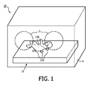
図1は、被検体106の(非侵襲的)モニタリングのためのシステム10を図示している。システム10は、「モニタリングシステム10」と交換可能に呼ばれることがある。システム10は、係合体(body of engagement)11、アクセスアパーチャ3を有する保育器4、複数の容量センサ143及び/又は他のコンポーネント(システム10内に含まれるものとして他の図面に図示されるコンポーネントを含む)のうちの1つ以上を含み得る。係合体11は、交換可能に「係合構造(structure of engagement)」、「構造」、「係合支持構造(support-structure of engagement)」又は「支持構造」とも呼ばれることがある。非限定的な例として、図3はシステム10aを概略的に図示しており、システム10aは、本明細書の他の箇所で説明されるように、システム10に帰属する全てのコンポーネント及び特徴を含んでよく、図3に図示されるように、電気ストレージ130、ユーザインタフェース120、1つ以上のプロセッサ110、1つ以上のコンピュータプログラムモジュール及び/又は他のコンポーネントを更に含んでよい。図3を参照すると、コンピュータプログラムモジュールは、結合モジュール111、選択モジュール112、再構築モジュール113及び/又は他のモジュールのうちの1つ以上を含み得る。図3には、システム10のユーザ108も図示されており、ユーザ108は、非限定的な例として、介護者、治療決定者(therapy-decision-maker)及び/又は医療専門家等である。
FIG. 1 illustrates a
心電図検査(ECG)を含め、被検体の心臓活動についての非侵襲的で、目立たず、かつ/又は動き耐性のある(motion-tolerant)判断は、特に新生児及び/又は乳幼児にとって、ダメージやストレス、痛み及び/又は侵襲的技術に関連する不快感を生じることなく、医学的及び/又は診断的に関連する情報の可用性に貢献することができる。本開示で説明される技術は、人間と動物の双方に適用可能である。そのようなモニタリングパラメータにおける経時的な変化は、特に関連があり得る。本明細書で使用されるとき、「非侵襲的」という用語は、センサを定位置に維持するために接着(adhesive)がないこと、かつ/又は皮膚に入る若しくは接着するか、任意の方法で被検体内に挿入される身体的装置がないこと、を指すことがある。接着型センサは、使用時に、(非常に薄い)皮膚にダメージを与え、ストレスや不快感及び/又は痛みを生じることがある。本明細書で使用されるとき、「動き耐性」という用語は、被検体106による有限運動(limited motion)の存在下で、信頼性のある測定値を得る能力を指すことがある。うごめき(wriggling)、腕、脚及び頭の動き、左右の回転、異なる体位間の遷移、興奮している又は具合の悪い被検体によって生じる動き、並びに/あるいは同様の動きは、有限運動として解釈される。一部の実施形態において、これらに限られないが、摂食(feeding)、おむつの交換、検査を受けること(test-taking)、新生児及び/又は乳幼児を治療又は世話をするときに一般的に行われる他のアクションを含め、被検体106の元の位置及び/又は定位置の処置は、被検体16が容量センサ143の所定の距離内にいる限りにおいて、有限運動として解釈され得る。この所定の距離は、特定の個々の容量センサに対して、特定の実施形態において使用される全ての容量センサに対して、複数の容量センサからの平均距離に対して、及び/又は特定の実施形態について指定される他のものに対して相対的なものとすることができる。被検体106が容量センサ143からの所定の距離を超えている時の期間中の測定値は、被検体106の実際の動きに関わらず、有限運動とは解釈されない。本開示で言及される医学的状態及び/又は問題は、限定ではなく例示であるように意図される。
Non-invasive, inconspicuous and / or motion-tolerant judgments about a subject's cardiac activity, including electrocardiography (ECG), can be particularly useful for newborns and / or infants, It can contribute to the availability of medically and / or diagnostically relevant information without causing pain and / or discomfort associated with invasive techniques. The techniques described in this disclosure are applicable to both humans and animals. Such changes in monitoring parameters over time can be particularly relevant. As used herein, the term “non-invasive” means that there is no adhesive to maintain the sensor in place and / or enters or adheres to the skin, or in any way. It may refer to the absence of a physical device inserted into the subject. Adhesive sensors can damage (very thin) skin and cause stress, discomfort and / or pain when used. As used herein, the term “motion tolerance” may refer to the ability to obtain reliable measurements in the presence of limited motion by the
図1を参照すると、係合体11は、被検体106、例えば新生児及び/又は乳幼児と係合するように構成される。一部の実施形態において、係合体11は、その上で被検体105を支持するように構成される(被検体)支持構造として実装され得る。対象の支持構造は、マットレス、ベッド、パッド、ブランケット、ラップ、枕、保育器、並びに/あるいは被検体106を係合及び/又は支持するのに適した他の構造であってよい。一部の実施形態において、係合体11は、被検体106によって着用され、かつ/又は被検体106を包むように構成される衣類であってよい。係合体11は、1つ以上のセンサ、例えば1つ以上の容量センサ143を支えるように構成され得る。例として、図2A及び図2Bは、係合体11及び複数の容量センサ143を含む、システム10の上面図を図示している。図2Aでは、被検体106は、係合体11の上に位置しており、したがって、図2Aでは点線で示されるように、1つ以上の容量センサ143は直接見える状態から遮られている。図2Bは、図2A内に図示されるものと同じシステム10及び同じ係合体を図示しているが、ビューの一部を遮る被検体106はない。図示される容量センサ143の数は単なる例示であり、いずれかに限定するようには意図されていない。図2Bに図示されるような、例えば花びらの形のような容量センサ143のパターン及び/又は配置は、単なる例示であり、いずれかに限定するように意図されていない。
Referring to FIG. 1, the
本明細書で使用されるとき、容量センサへの総称的な言及又は複数の容量センサに対する言及は、「容量センサ143」又は「容量センサ(複数可)143」という用語又は参照番号143を使用するその変形を使用することがあるが、図2Bに図示されるように、例えば「容量センサ143a」又は「容量センサ143b」のように参照番号に文字を付加することにより、特定の個々の容量センサを指すことがある。本開示は、図面のいずれかに示されるいずれのセンサの数又は位置にも限定されない。本明細書で使用されるとき、「測定する(measure)」という用語は、1つ以上のセンサによって生成される出力に基づく測定、推定及び/又は近似の任意の組合せを指す。本明細書で使用されるとき、「測定値(measurement)」という用語は、1つ以上のセンサによって生成される出力に基づく1つ以上の測定値、推定値、決定値、推論値及び/又は近似値の任意の組合せを指す。
As used herein, a generic reference to a capacitive sensor or a reference to a plurality of capacitive sensors uses the term “
容量センサ143は、まとめて感知情報と呼ばれる、1つ以上のタイプの情報を伝達する出力信号を生成するように構成され得る。特に、容量センサ143は、被検体106の電気生理学的パラメータに対して(例えば数学的関係を通して)予測可能な方法で関連する情報を伝達する出力信号、及び/又は被検体106の電気生理学的情報を伝達する出力信号を生成するよう構成され、これらの情報は、まとめて電気生理学的情報と呼ばれることがある。感知情報は、電気生理学的情報を含み得る。容量センサは、被検体106の皮膚が容量プレートの1つとして機能し、容量センサの電極がキャパシタの他の容量プレートとして機能するキャパシタを形成することができる。容量センサ143は、係合体11によって支持及び/又は担持され得る。
The
一部の実施形態において、容量センサ143は、2つの物体(例えばセンサ自体と被検体106)の間で電気及び/又は他の結合情報を伝達する出力信号を生成するように構成され得る。一部の実施形態において、検知情報は、結合情報及び/又は電気生理学的情報を含み得る。
In some embodiments,
一部の実施形態では、結合情報を、容量センサ143によって生成される信号の強度、強さ、大きさ(magnitude)、スペクトル情報、位相シフト及び/又は信号レベルにより伝えることができる。例えば図2Aを参照すると、一部の実施形態では、個々の容量センサ143aは、(これらには限られないが、電磁信号の公知の周波数、位相、形状、大きさ及び/又は他の特性を含む)1つ以上の既知の特性を有する信号(例えば電磁信号)を放射することができる。そのような放射信号は搬送波信号と呼ばれることがある。個々の容量センサ143aについての結合情報は、放射信号が個々の容量センサ143aによってどれほど良好に受け取られるかによって、及び/又はこれに基づいて決定され得る。感知情報は少なくとも、搬送波信号に対応するか、かつ/又は搬送波信号を表すコンポーネントを含み、このコンポーネントは、結合情報を決定するのに使用され、かつ/又はそのような決定を行うための基準(basis)として使用され得る。一部の実施形態において、感知情報は、変調搬送波信号(及び/又は搬送波信号の変調されたバージョン)を含んでもよく、変調搬送波信号は、容量センサ143と被検体106(の皮膚)との間の容量結合によって変調及び/又は影響された搬送波信号のバージョンである。
In some embodiments, the coupling information can be conveyed by the intensity, strength, magnitude, spectral information, phase shift and / or signal level of the signal generated by the
本明細書で使用されるとき、「容量センサ」という用語は、信号を受信及び/又は感知するための構造に限定されるようには意図されておらず、信号を伝送、放射、転送、ブロードキャスト、生成及び/又は作成するための構造を含み得る。そのような「容量センサ」は、交換可能に「容量トランシーバ」及びその派生語とも呼ばれることがある。容量センサ143aと被検体106との間の良好な及び/又は強い結合の場合、受け取った信号(例えば搬送波信号に対応する感知情報の一部又はコンポーネント)は、例えば容量センサ143aと被検体106との間の不十分な及び/又は弱い結合の場合と比べて、より大きな大きさを有することがある。
As used herein, the term “capacitive sensor” is not intended to be limited to structures for receiving and / or sensing a signal, but transmits, radiates, forwards, broadcasts a signal. May include structures for generating and / or creating. Such “capacitance sensors” may also be interchangeably referred to as “capacity transceivers” and their derivatives. In the case of good and / or strong coupling between the
一部の実施形態において、放射された搬送波信号に対応する(及び/又は放射された搬送波信号の表現である)感知情報の部分又はコンポーネントは、これらには限られないが電磁信号の周波数、位相、形状、大きさ及び/又は他の特性を含め、区別的な(電磁)特性を有することによって、電気生理学的情報を伝達する感知情報の部分又はコンポーネントから区別され得る。例えば電気生理学的情報は、周波数の(所定の)範囲及び/又は他の特性に(生理学的に)限定され得る。容量センサ143は、搬送波信号を放射するよう構成され得る。一部の実施形態において、放射される搬送波信号は、限定された範囲外の特性を有することがある。例えば容量センサ143によって放射される搬送波信号は、電気生理学的情報の周波数の範囲(例えば1kHz未満及び/又は容量センサ143について選ばれる及び/又は選択される適切な周波数未満/以上)よりも高い1つ以上の周波数(例えば約1kHz、約10kHz、約1MHz及び/又は他の適切な周波数)を有することがある。システム10は、フィルタリングにより、及び/又は本明細書で説明される、選ばれた及び/又は選択された区別的な特徴に適した信号処理技術を使用することにより、感知情報内の結合情報から、電気生理学的情報を区別することができる。本明細書の他の箇所で説明されるように、搬送波信号を使用してチャネル選択を実行することに加えて、搬送波信号を使用して心電図(ECG)信号を再構築することができる。
In some embodiments, the portion or component of the sensing information that corresponds to (and / or is a representation of the radiated carrier signal) corresponding to the radiated carrier signal is not limited to the frequency, phase of the electromagnetic signal. By having distinctive (electromagnetic) characteristics, including shape, size and / or other characteristics, it can be distinguished from the parts or components of the sensing information that convey electrophysiological information. For example, electrophysiological information may be limited (physiologically) to a (predetermined) range of frequencies and / or other characteristics. The
一部の実施形態において、システム10は、3、4、5、6、7、8又はそれ以上の容量センサ143を含むことができる。例として、図2Bは、8個の容量センサ143を含むシステム10の例示の実施形態を図示している。1つ又は2つの容量センサ143を使用するシステムは、動き耐性がないことがあり、かつ/又は、これらには限られないが、あおむけ、うつぶせ及び/又は横向きを含め、複数の異なる体位で信頼性のある測定値を決定することができないことがある。
In some embodiments, the
本開示におけるセンサは、出力信号を、継続的方法で、例えば1日を通して生成するように構成され得る。これは、断続的に、周期的(例えばサンプリングレートで)、連続的に、持続的に、可変の間隔で、かつ/又は1日、1週間、1か月の期間若しくは他の期間の少なくとも一部の間継続する他の方法で、信号を生成することを含み得る。サンプリングレートは、約0.001秒、0.01秒、0.1秒、1秒、約10秒、約1分及び/又は他のサンプリングレートとすることができる。複数の個々のセンサが、特定の出力信号及び/又はこれらから導出されるパラメータ(特定のパラメータに関連する周波数)に応じて、異なるサンプリングレートを使用して動作してもよいことが認識される。例えば一部の実施形態では、ベクトルが、被検体106の1つ以上のパラメータに関連して伝達される情報の複数のサンプルを含むように、生成される出力信号を、出力信号のベクトルと見なすことができる。異なるパラメータが異なるベクトルに関連し得る。出力信号のベクトルから継続的方法で決定される特定のパラメータを、その特定のパラメータのベクトルと見なすことができる。 The sensor in the present disclosure may be configured to generate the output signal in a continuous manner, for example throughout the day. This may be intermittent, periodic (eg, at a sampling rate), continuously, continuously, at variable intervals, and / or at least one day, one week, one month period, or other period. It may include generating the signal in other ways that continue during the part. The sampling rate can be about 0.001 second, 0.01 second, 0.1 second, 1 second, about 10 seconds, about 1 minute, and / or other sampling rates. It will be appreciated that multiple individual sensors may operate using different sampling rates depending on the particular output signal and / or the parameters derived therefrom (the frequency associated with the particular parameter). . For example, in some embodiments, the generated output signal is considered a vector of output signals such that the vector includes multiple samples of information communicated in connection with one or more parameters of the subject 106. be able to. Different parameters may be associated with different vectors. A particular parameter determined in a continuous manner from the vector of output signals can be considered as a vector of that particular parameter.
図3のシステム10(及び/又は図3に関連して交換可能に使用されるシステム10a)を参照すると、システム10は、情報を電気的に格納する電子記録媒体を備える電気ストレージ130を含み得る。電気ストレージ130の電子記録媒体は、システム10に一体的に提供される(すなわち、実質的に取外し不可能な)システムストレージ、及び/又は、例えばポート(例えばUSBポート、FireWire(登録商標)ポート等)若しくはドライブ(例えばディスクドライブ等)を介してシステム10に接続可能な取外し可能ストレージの一方又は双方を含む。電気ストレージ130は、光学的に読取可能な記録媒体(例えば光ディスク等)、磁気的に読取可能な記録媒体(例えば磁気テープ、磁気ハードドライブ、フロッピーディスク等)、電荷ベースの記録媒体(例えばEEPROM、RAM等)、半導体記録媒体(例えばフラッシュドライブ等)及び/又は他の電気的に読取可能な記録媒体のうちの1つ以上を含み得る。電気ストレージ130は、ソフトウェア・アルゴリズム、プロセッサ110によって決定される情報、ユーザインタフェース120を介して受け取る情報、及び/又はシステム10が正確に機能できるようにする他の情報を格納する。例えば電気ストレージ130は、(例えば本明細書において他の箇所で議論されるような)1つ以上のセンサによって(例えば経時的に)測定される出力信号から導出される1つ以上のパラメータ(のセット)及び/又は他の情報を記録又は格納することができる。電気ストレージ130は、システム10内の別個のコンポーネントであってよく、あるいは電気ストレージ130は、システム10の1つ以上の他のコンポーネント(例えばプロセッサ110)に一体的に提供されてよい。
Referring to
図3を参照すると、システム10は、システム10とユーザ(例えばユーザ108、介護者、治療決定者等)との間のインタフェースを提供するよう構成されるユーザインタフェース120を含んでよく、このユーザインタフェース120を通して、ユーザはシステム10へ情報を提供し、システム10から情報を受け取ることができる。このことは、データ、結果及び/又は指示、並びにまとめて「情報」と呼ばれる任意の他の通信可能なアイテムを、ユーザとシステム10との間で通信することを可能にする。ユーザインタフェース120に含めるのに適したインタフェースデバイスの例には、キーパッド、ボタン、スイッチ、キーボード、ノブ、レバー、ディスプレイスクリーン、タッチスクリーン、スピーカ、マイクロフォン、インジケータ光、可聴アラーム及びプリンタが含まれる。情報は、例えばユーザインタフェース120によって、聴覚信号、視覚信号、触覚信号及び/又は他のセンサ信号の形式でユーザ108へ提供され得る。
With reference to FIG. 3, the
非限定的な例として、特定の実施形態では、ユーザインタフェース120は、光を放射することができる放射源を含む。放射源は、LED、光バルブ、ディスプレイスクリーン及び/又は他のソースのうちの1つ以上を含む。ユーザインタフェース120は、例えば被検体106による所定の心拍閾値の突破(breaching)に関連して、例えばユーザ108に情報を伝達する方法で光を放射するよう、放射源を制御することができる。
As a non-limiting example, in certain embodiments,
理解されるように、ハードワイヤード又は無線のいずれかの他の通信技術も、本明細書ではユーザインタフェース120として考えられる。例えば一実施形態では、ユーザインタフェース120は、電気ストレージ130によって提供される取外し可能なストレージインタフェースに統合される。この例では、情報は、ユーザがシステム10の実装をカスタマイズすることを可能にする取外し可能なストレージ(例えばスマートカード、フラッシュドライブ、取外し可能ディスク等)からシステム10へロードされる。ユーザインタフェース120としてシステム10とともに使用するのに適合される他の例示の入力デバイス及び技術には、これらに限られないが、RS-232ポート、RFリンク、IRリンク、モデム(電話、ケーブル、Ethernet(登録商標)、インターネット又はその他)が含まれる。簡潔に言うと、システム10と情報を通信するための任意の技術がユーザインタフェース120と考えられる。
As will be appreciated, other communication technologies, either hardwired or wireless, are also contemplated herein as
図3を参照すると、プロセッサ110は、システム10における情報処理能力を提供するように構成される。したがって、プロセッサ110は、デジタルプロセッサ、アナログプロセッサ、情報を処理するように設計されるデジタル回路、情報を処理するように設計されるアナログ回路及び/又は情報を電子的に処理するための他の機構のうちの1つ以上を含む。図3ではプロセッサ110は単一のエンティティとして図示されているが、これは単に例示の目的のためである。一部の実施形態では、プロセッサ110は複数の処理ユニットを含む。
With reference to FIG. 3, the
図3に示されるように、プロセッサ110は、1つ以上のコンピュータプログラムモジュールを実行するよう構成される。1つ以上のコンピュータプログラムモジュールは、結合モジュール111、選択モジュール112、再構築モジュール113及び/又は他のモジュールを含む。プロセッサ110は、ソフトウェア;ハードウェア;ファームウェア;ソフトウェア、ハードウェア及び/又はファームウェアの何らかの組合せ;及び/又はプログラム可能なハードウェアを含め、プロセッサ110における処理能力を構成するための他の機構により、モジュール111〜113を実行するよう構成され得る。
As shown in FIG. 3, the
図3ではモジュール111〜113は単一の処理ユニット内で同じ場所にあるように図示されているが、プロセッサ110が複数の処理ユニットを含む実装では、モジュール111〜113のうちの1つ以上が他のモジュールとはリモートに配置されてもよいことを認識されたい。モジュール111〜113のいずれかが、説明されるものよりも多く又は少ない機能を提供することもあるので、以下で説明される異なるモジュール111〜113によって提供される機能の説明は例示の目的であり、限定するように意図されていない。例えばモジュール111〜113のうちの1つ以上を省略してもよく、その機能の一部又は全てがモジュール111〜113のうちの他のモジュールによって提供されてもよい。プロセッサ110は、モジュール111〜113の1つに帰属する機能の一部又は全てを実行することができる、1つ以上の追加モジュールを実行するように構成されてもよいことに留意されたい。
In FIG. 3, modules 111-113 are illustrated as being in the same location within a single processing unit, but in implementations where
図3のシステム10の結合モジュール111は、システム10の1つ以上の容量センサ143について結合レベルを決定するように構成される。本明細書で使用されるとき、「結合レベル」という用語は、(例えば電気信号の)結合の強さ及び/又は(例えば電気信号の)信号の強さを指すことがある。一部の実施形態において、結合レベルは、強度、振幅、強さ、大きさ(規模)、エネルギー含量、容量レベル、スペクトル情報、位相シフト及び/又は他のタイプのレベル及び/又はその組合せに基づくものとすることができ、容量センサ143からの出力信号を信頼できるものと見なすべきかどうか(及び/又はどの程度まで)を示すことができる。あるいは、かつ/又は同時に、一部の実施形態では、結合レベルは、例えば他の容量センサ143からのより強い及び/又はより信頼できる信号の方を選んで、容量センサ143からの出力信号を破棄すべきかどうかを示すことができる。結合モジュール111による結合レベルの決定は、出力信号全体(例えば感知情報全体)に基づいてもよく、あるいは、その1つ以上の部分又はコンポーネント(例えば結合情報に対応する1つ以上の部分又はコンポーネント)に基づいてもよい。例えば一部の実施形態では、特定の容量センサ143aについての結合レベルは、出力信号のうち、特定の周波数範囲内に入る部分、例えば1kHz超の部分の大きさに基づくものとすることができる。特定の周波数範囲内に入る出力信号の部分は、結合情報に対応する。一部の実施形態では、結合情報は、出力信号の一部分の代わりに、出力信号全体の特性に基づくものであってもよい。
The
個々の容量センサ143の結合レベルは、例えば取られる個々の測定値の間で経時的に変化し得る。経時的な結合レベルの変化は、例えば被検体106の動きによって生じることがある。結合モジュール111は、容量センサ143の結合レベルを、1つ以上の他の容量センサ143からの結合レベルに対して順序付けし、ランク付けし、かつ/又は他の方法で比較するように構成され得る。変化する結合レベルを同じ又は同様のサンプリングレートで再評価して、関連する容量センサ143からの対応する測定値を使用すべきか破棄すべきかを判断することができるように、結合モジュール111は、同じ又は同様のサンプリングレートで容量センサ143の一部又は全ての結合レベルを決定するように構成され得る。
The coupling level of the individual
一部の実施形態において、結合モジュール111は、容量センサ143のセットから、どの特定の容量センサ143が最も高い及び/又は最も強い結合レベルを有するかを決定するよう構成され得る。この特定の容量センサ143を、最大容量センサと呼ぶことがある。最大容量センサは、例えば双方の容量センサに対して取られている測定値の後に、ある特定の容量センサ143aから別の特定の容量センサ143bへ変化し得る。最大容量センサの結合レベルは、最大結合レベルと呼ばれることがある。一部の実施形態において、結合モジュール111は、1つ以上の容量センサ143についての集約結合レベル(aggregate coupling level)を決定するように構成され得る。例えば集約結合レベルは、集約値、平均値、標準偏差、分散及び/又は複数の結合レベルから1つの出力値を生成する他の統計的及び/又は集約関数、のうちの1つ以上に基づくものであってよい。集約結合レベルを決定するのに使用される結合レベルは、全ての利用可能な容量センサ143からの結合レベル、最大容量センサ以外の全ての利用可能な容量センサからの結合レベル、少なくとも最小結合閾値を突破するのに十分に高い又は強い結合レベルを有する全ての容量センサ143からの結合レベル、少なくとも最小結合閾値を突破するのに十分高い又は強い結合レベルを有する、最大センサ以外の全ての利用可能な容量センサからの結合レベル、及び/又は例えばサンプリングレートで取られている測定値の後に再評価することができる容量センサ143の他のサブセットからの結合レベルを含んでよい。
In some embodiments, the
図3のシステム10の選択モジュール112は、1つ以上の容量センサ143を選択するように構成される。選択モジュール112は、複数の選択を順番に適用して、1つ以上の容量センサ143を破棄することができる。1つ以上の選択された容量センサからの出力信号は、例えば再構築モジュール113によって心電図(ECG)信号及び/又はパラメータを決定するのに使用され得る。選択モジュール112による選択は、結合モジュール111によって決定される結合レベルに基づくものであってよい。一部の実施形態では、最小結合閾値未満の結合レベルは、選択から自動的に除外され得る。一部の実施形態では、十分な結合閾値超の結合レベルは、自動的に選択に含められる。一部の実施形態において、最小結合閾値は絶対値であってよい。一部の実施形態では、最小結合閾値は、最大結合レベルと、及び/又は容量センサの対応するサブセットからの結合レベルの値のサブセットに基づく集約結合レベルとの一方又は双方に依存するか、かつ/又はこれに基づくものであってよい。一部の実施形態において、十分な結合閾値は絶対値であってよい。一部の実施形態では、十分な結合レベル閾値は、最大結合レベルと、及び/又は容量センサの対応するサブセットからの結合レベルの値のサブセットに基づく集約結合レベルとの一方又は双方に依存するか、かつ/又はこれに基づくものであってよい。
The
例えば一部の実施形態では、選択モジュール112による選択は、最大結合レベル(例えば結合情報に対応する周波数範囲の最大エネルギー含量又は(実質的に)全ての感知情報についての最大振幅を有する出力信号)と、他の(最大でない)結合センサについての結合レベルとの間の比較に基づくものであってもよい。比較は、これらの結合レベルの比、分散並びに/あるいは他の数学的及び/又は統計的操作に基づくものであってよい。例えば最大結合レベルの分散を、1つ以上の他の結合レベルの分散と比較して、選択モジュール112による選択を決定してもよい。「実質的に全ての感知情報(substantially the entire sensed information)」という用語は、電気生理学的情報の全て又はほとんどを含み、かつ結合情報の全て又はほとんどを含む感知情報をとして解釈され得る。一部の実施形態において、感知情報は、説明されるような選択モジュール112による使用に先行して処理される。例えば低周波数閾値未満の信号コンポーネントは、破棄されることがある。低周波数閾値は20Hz、15Hz、10Hz、5Hz、4Hz、3Hz、2Hz、1Hz及び/又は別の適切な低周波数閾値とすることができる。そのように処理される感知情報は、「実質的に全ての感知情報」と呼ばれることがある。
For example, in some embodiments, the selection by the
一部の実施形態において、選択モジュール112による選択は、例えばその比較を使用する、1つ以上の相関係数に基づくものであってよい。相関係数は、2つの容量センサ143からの出力信号間及び/又は2つの対応する結合レベル間で決定され得る。相関係数は、ピアソンの相関係数、ランク相関及び/又は他のタイプの統計的相関のうちの1つ以上を含み得る。最大容量センサが決定されたと仮定すると、第1の相関係数は、対応する最大結合レベルと、第1の特定の容量センサ143aの結合レベルとの間で決定され得る。第2の相関係数は、最大結合レベルと、第2の特定の容量センサ143bの結合レベルとの間で決定され、他の(場合によっては、本明細書の別の箇所で説明されるような他の理由で事前選択される)容量センサの更なる結合レベルについても同様に決定され得る。選択モジュール112による選択は、第1の相関係数と、第2の相関係数と、同様の相関係数等との間の比較に基づくことができる。例えば選択モジュール112は、最小相関閾値未満の(最大結合レベルの)対応する相関係数を有する容量センサからの出力信号を破棄することができる。
In some embodiments, the selection by
一部の実施形態において、選択モジュール112による選択は、特定の容量センサの出力信号内に含まれる情報の量の定量化に基づくものであってよい。情報の量は、最大センサからの出力信号とは独立に決定されてもよく、あるいはその出力信号に対して相対的に決定されてもよい。例えば2つの容量センサ、第1及び第2の容量センサが、同じ又は良く似た出力信号を生成した場合、第1の容量センサによって提供される情報に対して、第2の容量センサによって追加される追加の情報の量は、小さいか及び/又は限定的であり、第2の容量センサを選択モジュール112による選択から除外するための基準を形成し得る。
In some embodiments, the selection by
一部の実施形態において、選択モジュール112による選択は、複数の容量センサ143の空間分布に基づくものであってよい。空間分布を使用して、係合体11のうち最も大きな利用可能エリアを覆う容量センサ143を選択することを選んでもよい。一部の実施形態において、容量センサ143のセットは、重み付け行列(weighing matrix)に対応する。選択モジュール112による選択は、重み付け行列における重みを調整及び/又は調節することによって実装されてもよい。一実施形態において、空間分布は近接であることを不利にすることができる。例えば第1及び第2の容量センサは、空間分布を考慮することによる何らかの決定(例えば最大容量センサとの比較)に従って同様の結合レベルを有する場合、第1の容量センサは、最大容量センサから最も遠いために第2の容量センサより好まれることがある。反対に、第2の容量センサは、最大容量センサに最も近いために、(例えば重み付け行列における重み因子を減らすことによって)不利にされることがある。一部の実施形態では、空間分布は単に、最小結合レベルを有する最小の数の容量センサ143に少なくとも応答して、かつ/又は他の条件に応答して使用されてもよい。
In some embodiments, selection by
選択モジュール112は、例えば第1の選択、第2の選択等を含め、複数の選択を決定するように構成されてもよい。複数の選択は、順番に及び/又は同時に決定及び/又は実行され得る。選択は、容量センサが、信頼性のある及び/又は有益な情報を生成したと考えられるフィルタとして機能し得る。例えば第1の選択は、(他の箇所で説明されるように)容量センサ143のセットの結合レベルの振幅に基づくものであってよく、したがって、容量センサ143の第1のサブセットを確立し、第1のサブセット外の容量センサからの感知情報を破棄する。そのようなサブセットの選択は、選択の「合致(meeting)」又は「通過(passing)」と呼ばれることがある。第2の選択は、最大結合レベルと、第1のサブセット内の容量センサの結合レベルとの間の相関係数の比較に基づくものであってよい。第2の選択に基づいて、第1のサブセットのサブセットを形成する第2のサブセットが決定され、したがって、第2のサブセット外の容量センサ143からの感知情報を破棄する。選択モジュール112は、第1及び第2の選択に限定されず、むしろ、2つ、3つ又はそれ以上の選択のセットを実行するように構成されてよく、全ての実行された選択に合致及び/又は通過する容量センサのみを含む、選択された容量センサの最後のサブセットが決定されるまで、これらの選択が、順次又は繰り返し適用されて個々の容量センサ(及び対応する感知情報)を破棄する。
The
図3のシステム10の再構築モジュール113は、心電図(ECG)信号を決定するように構成される。再構築モジュール113による決定は、1つ以上の容量センサ143によって生成される出力信号に基づくものであってよい。一部の実施形態において、再構築モジュール113による決定は、例えば選択モジュール112によって選択されるような、選択された容量センサのサブセットによる出力信号に基づくことがある。再構築モジュール113による動作は、Vullings等による2010年1月20日出願の「Fetal Monitoring」という名称の米国特許出願第8,332,021号明細書(特許文献1)に説明される技術に基づくものであってよい。あるいは、かつ/又は同時に、再構築モジュール113の動作は、ブラインド音源分離法、テンプレートマッチングアプローチ及び/又は放射された搬送波信号の使用に基づく技術のような、心電図(ECG)再構築のために使用することができる他の技術に基づくものとすることができる。再構築モジュール113によって実行される例示の動作は、以下のうちの1つ以上を含み得る:ローパスフィルタを適用して、周辺電子デバイスによって生じる1つ以上の(約)50Hzから(約)60Hzのノイズ信号を除去し、選択された容量センサからの出力信号に基づいて、ベクトル心電図(図4Aに図示されるVCG)を決定することと、楕円により幾つかの重なった心拍(図4Aを参照されたい)についてベクトル心電図(VCG)を近似することと、ベクトル心電図(VCG)を楕円の軸上に投影するか、あるいは投影から得られる再構築された心電図(ECG)信号に対する最大Rピーク検出に適した別の投影を実行すること:のうちの1つ以上を含み得る。
The
再構築モジュール113の動作における追加のステップは、標準的なECG分析で一般的に使用され得るように、再構築信号に対するRピーク検出を実行すること、検出されたRピークを使用してKalmanフィルタリングを適用すること及び/又はKalmanフィルタされた信号からベクトル心電図(VCG)信号を再計算して、VCG信号を標準のEinthovenリードに投影することを含み得る。Kalmanフィルタリングは、逐次ECG推定のBayesianエビデンス関数を最大化することにより、そして、それぞれ幾つかの同時に記録される信号の間の空間相関を用いることにより実装され得る。したがって、得られるノイズ共分散推定をKalmanフィルタリングにおいて使用し、より最近取得された感知情報が、形態学的変動(morphological variability)を含む場合は、より多くの重みを感知信号に割り当てるか及び/又は帰属させ、形態学的変動がないか顕著な形態学的変動がない場合は、より少ない重みを割り当てるか及び/又は帰属させることができる。
An additional step in the operation of the
例として、図4Bは、一般的に使用される技術を通して生成され得る、幾つかの心拍を示す参照ECG信号42を図示している。X軸は時間を示し、Y軸はボルト単位の振幅を示す。図4Aは、検査中に測定された、7個の容量センサからの出力信号に基づいて、決定されたベクトル心電図(VCG)信号41を図示している。X軸及びY軸は、容量センサが置かれる面の距離を表す。図4Aには幾つかの重なった心拍が示されている。図4Cは、図4Aからの決定されたVCG信号に基づく、再構築されたECG信号43を図示している。再構築されたECG信号43は、参照ECG信号42に密接に対応する。Rピーク44は、再構築されたECG信号43において明確に検出及び/又は示される。
As an example, FIG. 4B illustrates a
図5は、被検体106の心電図検査(ECG)モニタリングを提供する方法500を図示している。以下で提示される方法500の動作は例示であるように意図される。特定の実施形態において、方法500は、説明されない1つ以上の追加の動作とともに達成されてもよく、かつ/又は議論される動作の1つ以上を用いずに達成されてもよい。加えて、方法500の動作が図5で図示され、以下で説明される順序は、限定するように意図されていない。
FIG. 5 illustrates a
特定の実施形態において、方法500は、1つ以上の処理デバイス(例えばデジタルプロセッサ、アナログプロセッサ、情報を処理するように設計されるデジタル回路、情報を処理するように設計されるアナログ回路、かつ/又は情報を電子的に処理するための他の機構)で実装され得る。1つ以上の処理デバイスは、電子記録媒体上に電子的に格納される命令に応じて方法500の動作の一部又は全てを実行する、1つ以上のデバイスを含み得る。1つ以上の処理デバイスは、方法500の動作の1つ以上の実行のために特別に設計されるよう、ハードウェア、ファームウェア及び/又はソフトウェアを通して構成される1つ以上のデバイスを含み得る。
In certain embodiments, the
動作502において、搬送波信号が、被検体に近接する複数の容量センサによって放射される。一部の実施形態において、動作502は、(図1及び図2に図示され、本明細書で説明される)容量センサ143と同一又は類似の容量センサによって実行される。
In
動作504において、被検体の電気生理学的情報を伝達する出力信号が生成される。出力信号は、放射される搬送波信号の表現を含む。一部の実施形態において、動作504は、(図1及び図2に図示され、本明細書で説明される)容量センサ143と同一又は類似の容量センサによって実行される。
In
動作506において、生成された出力信号に基づいて、容量センサのうちの個々の容量センサについて、結合レベルが決定される。一部の実施形態において、動作506は、(図3に図示され、本明細書で説明される)結合モジュール111と同一又は類似の容量センサによって実行される。
In
動作508において、1つ以上の容量センサが、決定された結合レベルに基づいて選択される。一部の実施形態において、動作508は、(図3に図示され、本明細書で説明される)選択モジュール112と同一又は類似の容量センサによって実行される。
In
動作510において、心電図(ECG)信号が、選択された1つ以上の容量センサからの生成された出力信号に基づいて決定される。一部の実施形態において、動作510は、(図3に図示され、本明細書で説明される)再構築モジュール113と同一又は類似の容量センサによって実行される。
In
特許請求の範囲において、括弧内に記載される任意の参照符号は、請求項を限定するものとして解釈されるべきではない。「備える」又は「含む」という用語は、請求項内に列挙されない要素又はステップ以外の存在を除外しない。幾つかの手段を列挙するデバイスの請求項において、これらの要素の幾つかは、ハードウェアの1つ及び同じアイテムで具現化されてよい。ある要素に先行する「a」、「an」という冠詞は、そのような要素の複数の存在を除外しない。幾つかの手段を列挙するデバイスの請求項において、これらの要素の幾つかは、ハードウェアの1つ及び同じアイテムで具現化されてよい。特定の手段が相互に異なる従属請求項に記載されているという単なる事実は、これらの手段の組合せを有利に使用することができないことを示唆するものではない。 In the claims, any reference signs placed between parentheses shall not be construed as limiting the claim. The terms “comprising” or “including” do not exclude the presence of elements or steps other than those listed in a claim. In the device claim enumerating several means, several of these elements may be embodied by one and the same item of hardware. The articles “a” and “an” preceding an element do not exclude the presence of a plurality of such elements. In the device claim enumerating several means, several of these elements may be embodied by one and the same item of hardware. The mere fact that certain measures are recited in mutually different dependent claims does not indicate that a combination of these measured cannot be used to advantage.
本明細書は、説明の目的で、現在最も実践的かつ好適な実施形態であると考えられるものに基づく詳細を含むが、理解されるように、そのような詳細はそのような目的のためだけであり、本開示は、開示される実施形態に限定されず、反対に、添付の特許請求の範囲の精神及び範囲内にある修正及び均等な配置を網羅するように意図される。例えば理解されるように、任意の実施形態の拡張の可能性のある1つ以上の特徴は、任意の他の実施形態の1つ以上の特徴と組み合されることが考えられる。 This specification includes details based on what is presently considered to be the most practical and preferred embodiment for purposes of explanation, but as will be understood, such details are only for such purposes. Thus, the present disclosure is not limited to the disclosed embodiments, but on the contrary is intended to cover modifications and equivalent arrangements that are within the spirit and scope of the appended claims. For example, as will be appreciated, it is contemplated that one or more features that may be expanded in any embodiment may be combined with one or more features in any other embodiment.
Claims (17)
前記被検体の電気生理学的情報を伝達する出力信号を生成するよう構成される複数の非侵襲的容量センサであって、該複数の容量センサは、前記被検体への取り付けのない少なくとも3つの非侵襲的容量センサを含み、該非侵襲的容量センサは、搬送波信号を放射するよう更に構成され、前記非侵襲的容量センサの個々の1つの前記生成された出力信号は、前記被検体の電気生理学的信号であり、該生理学的信号は、前記搬送波信号の表現を含む、複数の非侵襲的容量センサと;
コンピュータプログラムモジュールと;
前記コンピュータプログラムモジュールを実行するよう構成される1つ以上のプロセッサと;
を備え、前記コンピュータプログラムモジュールは:
前記生成された出力信号に基づいて、前記非侵襲的容量センサの個々の容量センサについて、結合レベルを決定するよう構成される、結合モジュールと、
前記決定された結合レベルに基づいて、1つ以上の容量センサを選択するよう構成される、選択モジュールと、
前記選択された1つ以上の容量センサからの前記生成された出力信号に基づいて、心電図(ECG)信号を決定するよう構成される、再構築モジュールと、
を備え、前記結合モジュールは、どの容量センサが最も高い結合レベルを有するかを決定するように更に構成され、前記1つ以上の容量センサの選択は、前記最も高い結合レベルを有する容量センサによって生成された出力信号と、1つ以上の他の容量センサによって生成された出力信号との間の1つ以上の相関係数に基づき、該相関係数は、ピアソンの相関係数とランク相関係数のうちの少なくとも一方を含む、システム。 A system for electrocardiogram (ECG) monitoring of a subject comprising:
A plurality of non-invasive capacitive sensors configured to generate an output signal conveying electrophysiological information of the subject , wherein the plurality of capacitive sensors are at least three non- attached to the subject; An invasive capacitive sensor, wherein the non-invasive capacitive sensor is further configured to emit a carrier signal, and the generated output signal of each individual one of the non-invasive capacitive sensors is the electrophysiology of the subject A plurality of non-invasive capacitive sensors including a representation of the carrier signal;
A computer program module;
One or more processors configured to execute the computer program modules;
The computer program module comprises:
A coupling module configured to determine a coupling level for each capacitive sensor of the non-invasive capacitive sensor based on the generated output signal;
A selection module configured to select one or more capacitive sensors based on the determined coupling level;
A reconstruction module configured to determine an electrocardiogram (ECG) signal based on the generated output signal from the selected one or more capacitive sensors;
And the coupling module is further configured to determine which capacitive sensor has the highest coupling level, wherein the selection of the one or more capacitive sensors is generated by the capacitive sensor having the highest coupling level. Based on one or more correlation coefficients between the generated output signal and an output signal generated by one or more other capacitive sensors, the correlation coefficient is Pearson's correlation coefficient and rank correlation coefficient A system comprising at least one of the following.
請求項1に記載のシステム。 The coupling module is further configured to determine which capacitive sensor has the highest coupling level;
The system of claim 1.
請求項1に記載のシステム。 The selection of the one or more capacitive sensors is further based on a spatial distribution of the one or more capacitive sensors.
The system of claim 1.
請求項1に記載のシステム。 The reconstruction module determines a vector electrocardiogram (VCG) signal based on the generated output signal from the selected one or more capacitive sensors and approximates the vector electrocardiogram signal by an ellipse having a major axis. And configured to determine the electrocardiogram signal by projecting the vector electrocardiogram signal onto the major axis of the ellipse,
The system of claim 1.
請求項1に記載のシステム。 The plurality of non-invasive capacitive sensors are configured to generate an output signal that is non-invasive and motion resistant to a finite motion of the subject.
The system of claim 1.
患者と物理的に接触しない複数の非侵襲的容量センサによって搬送波信号を放射するステップであって、該複数の容量センサは、少なくとも3つの非侵襲的容量センサを含む、ステップと;
前記複数の容量センサによって、前記被検体の電気生理学的情報を伝達する出力信号を生成するステップであって、前記非侵襲的容量センサの個々の1つの前記出力信号は、前記被検体の電気生理学的信号であり、該生理学的信号は、前記搬送波信号の表現を含む、ステップと;
前記生成された出力信号に基づいて、前記容量センサの個々の容量センサについて、結合レベルを決定するステップであって、どの容量センサが最も高い結合レベルを有するかを決定することを含む、ステップと;
前記最も高い結合レベルを有する容量センサによって生成された出力信号と、1つ以上の他の容量センサによって生成された出力信号との間の1つ以上の相関係数に基づき、前記決定された結合レベルに基づいて、1つ以上の容量センサを選択するステップと;
前記選択された1つ以上の容量センサからの前記生成された出力信号に基づいて、心電図(ECG)信号を決定するステップと;
を含み、
前記1つ以上の容量センサを選択するステップは、前記最も高い結合レベルを有する容量センサによって生成された出力信号と、1つ以上の他の容量センサによって生成された出力信号との間の1つ以上の相関係数に基づき、該相関係数は、ピアソンの相関係数とランク相関係数のうちの少なくとも一方を含む、方法。 A method for providing electrocardiogram (ECG) monitoring of a subject, the method comprising:
Comprising the steps of: emitting a carrier signal by a plurality of non-invasive capacitive sensor which does not contact with the patient physically, the plurality of capacitive sensors comprises at least three non-invasive capacitive sensor, comprising the steps;
Generating output signals conveying electrophysiological information of the subject by the plurality of capacitive sensors, wherein each one of the output signals of the non-invasive capacitive sensor is an electrical signal of the subject; A physiological signal, the physiological signal comprising a representation of the carrier signal;
Determining a coupling level for each of the capacitive sensors of the capacitive sensor based on the generated output signal, comprising determining which capacitive sensor has the highest coupling level ; ;
The determined coupling based on one or more correlation coefficients between an output signal generated by the capacitive sensor having the highest coupling level and an output signal generated by one or more other capacitive sensors Selecting one or more capacitive sensors based on the level;
Determining an electrocardiogram (ECG) signal based on the generated output signal from the selected one or more capacitive sensors;
Only including,
Selecting the one or more capacitive sensors includes one of an output signal generated by the capacitive sensor having the highest coupling level and an output signal generated by one or more other capacitive sensors. Based on the above correlation coefficient, the correlation coefficient includes at least one of a Pearson correlation coefficient and a rank correlation coefficient .
請求項6に記載の方法。 The selection of the one or more capacitive sensors is further based on a spatial distribution of the one or more capacitive sensors.
The method of claim 6 .
前記選択された1つ以上の容量センサからの前記生成された出力信号に基づいて、ベクトル心電図(VCG)信号を決定するステップと、
長軸を有する楕円によって前記ベクトル心電図信号を近似するステップと、
前記楕円の前記長軸上に前記ベクトル心電図信号を投影するステップと、
を含む、請求項6に記載の方法。 Determining the electrocardiogram (ECG) signal comprises:
Determining a vector electrocardiogram (VCG) signal based on the generated output signal from the selected one or more capacitive sensors;
Approximating the vector electrocardiogram signal by an ellipse having a major axis;
Projecting the vector electrocardiogram signal onto the major axis of the ellipse;
The method of claim 6 comprising:
請求項6に記載の方法。 It said plurality of non-invasive capacitive sensor is configured to generate an output signal with a non-invasive and motion resistance to the finite movement of the subject,
The method of claim 6 .
請求項6に記載の方法。 The method of claim 6.
搬送波信号を放射するよう構成される複数の要素を含む、搬送波信号放射手段であって、前記複数の要素が少なくとも3つの非侵襲的要素を含む、搬送波信号放射手段と;
前記被検体の電気生理学的情報を伝達する出力信号を生成するための出力信号生成手段であって、個々の要素の前記出力信号が、前記個々の要素によって放射される前記搬送波信号の表現を含み、当該出力信号生成手段は前記被検体に対して非侵襲的である、出力信号生成手段と;
前記生成された出力信号に基づいて、前記搬送波信号放射手段について結合レベルを決定するための結合レベル決定手段と;
前記決定された結合レベルに基づいて、前記搬送波信号放射手段のうちの1つ以上の要素を選択するための選択手段と;
前記選択手段によって選択される前記選択された要素からの前記生成された出力信号に基づいて、心電図(ECG)信号を決定するための心電図(ECG)信号決定手段と;
を含み、
前記結合レベル決定手段は、どの非侵襲的要素が最も高い結合レベルを有するかを決定するよう構成され、前記選択手段の選択は、前記最も高い結合レベルを有する非侵襲的要素によって生成される出力信号と、1つ以上の他の非侵襲的要素によって生成される出力信号との間の1つ以上の相関係数に基づき、該相関係数は、ピアソンの相関係数とランク相関係数のうちの少なくとも一方を含む、システム。 A system configured to provide electrocardiogram (ECG) monitoring of a subject, the system:
Carrier signal radiating means including a plurality of elements configured to radiate a carrier signal, wherein the plurality of elements include at least three non-invasive elements;
Output signal generating means for generating an output signal conveying electrophysiological information of the subject, wherein the output signal of an individual element includes a representation of the carrier signal emitted by the individual element The output signal generating means is non-invasive to the subject, and the output signal generating means;
Coupling level determining means for determining a coupling level for the carrier signal radiating means based on the generated output signal;
Selecting means for selecting one or more elements of the carrier signal emitting means based on the determined coupling level;
Electrocardiogram (ECG) signal determination means for determining an electrocardiogram (ECG) signal based on the generated output signal from the selected element selected by the selection means;
Only including,
The coupling level determination means is configured to determine which non-invasive element has the highest coupling level, the selection of the selection means being an output generated by the non-invasive element having the highest coupling level Based on one or more correlation coefficients between the signal and an output signal generated by one or more other non-invasive elements, the correlation coefficient is a Pearson correlation coefficient and a rank correlation coefficient A system that includes at least one of them .
請求項11に記載のシステム。 The operation of the selection means is further based on a spatial distribution of the one or more elements of the carrier signal radiating means,
The system of claim 11 .
前記選択された1つ以上の容量センサからの前記生成された出力信号に基づいて、ベクトル心電図(VCG)信号を決定するための手段と、
長軸を有する楕円によって前記ベクトル心電図信号を近似するための手段と、
前記楕円の前記長軸上に前記ベクトル心電図信号を投影するための手段と、
を含む、請求項11に記載のシステム。 The electrocardiogram (ECG) signal determining means includes:
Means for determining a vector electrocardiogram (VCG) signal based on the generated output signal from the selected one or more capacitive sensors;
Means for approximating the vector electrocardiogram signal by an ellipse having a major axis;
Means for projecting the vector electrocardiogram signal onto the major axis of the ellipse;
The system of claim 11 , comprising:
請求項11に記載のシステム。 It said output signal generating means is configured to generate an output signal with a non-invasive and motion resistance to the finite movement of the subject,
The system of claim 11 .
請求項11に記載のシステム。 The system of claim 11.
請求項15に記載のシステム。 The system according to claim 15.
請求項11に記載のシステム。 The system of claim 11.
Applications Claiming Priority (3)
| Application Number | Priority Date | Filing Date | Title |
|---|---|---|---|
| US201361908193P | 2013-11-25 | 2013-11-25 | |
| US61/908,193 | 2013-11-25 | ||
| PCT/IB2014/066281 WO2015075692A1 (en) | 2013-11-25 | 2014-11-24 | Electrocardiography monitoring system and method |
Publications (3)
| Publication Number | Publication Date |
|---|---|
| JP2016537181A JP2016537181A (en) | 2016-12-01 |
| JP2016537181A5 JP2016537181A5 (en) | 2018-08-02 |
| JP6420845B2 true JP6420845B2 (en) | 2018-11-14 |
Family
ID=52101365
Family Applications (1)
| Application Number | Title | Priority Date | Filing Date |
|---|---|---|---|
| JP2016554938A Active JP6420845B2 (en) | 2013-11-25 | 2014-11-24 | ECG monitoring system and method |
Country Status (8)
| Country | Link |
|---|---|
| US (1) | US10064566B2 (en) |
| EP (1) | EP3073909B1 (en) |
| JP (1) | JP6420845B2 (en) |
| CN (1) | CN106028923B (en) |
| CA (1) | CA2931433A1 (en) |
| MX (1) | MX2016006542A (en) |
| RU (1) | RU2683205C1 (en) |
| WO (1) | WO2015075692A1 (en) |
Families Citing this family (16)
| Publication number | Priority date | Publication date | Assignee | Title |
|---|---|---|---|---|
| CN107205678B (en) * | 2014-09-23 | 2019-11-29 | Rr图形逻辑有限公司 | Contactless electrocardiogram system |
| US11534104B2 (en) | 2014-10-29 | 2022-12-27 | Bloom Technologies NV | Systems and methods for contraction monitoring and labor detection |
| JP6766052B2 (en) | 2015-01-27 | 2020-10-07 | アップル インコーポレイテッドApple Inc. | Systems and methods for determining sleep quality |
| DE102015111658B4 (en) | 2015-07-17 | 2018-11-29 | Capical Gmbh | System, method and computer program for the capacitive detection of electrical biosignals |
| US20170347960A1 (en) * | 2016-06-06 | 2017-12-07 | General Electric Company | Mobile newborn care bed and methods of newborn care |
| DE102016112391A1 (en) * | 2016-07-06 | 2018-01-25 | Capical Gmbh | treatment table |
| US10512432B2 (en) | 2016-08-12 | 2019-12-24 | Apple Inc. | Vital signs monitoring system |
| US10307073B2 (en) * | 2016-12-21 | 2019-06-04 | General Electric Company | ECG sensor with capacitive defibrillation protection |
| WO2018211403A1 (en) | 2017-05-15 | 2018-11-22 | Bloom Technologies NV | Systems and methods for monitoring fetal wellbeing |
| CN110612060B (en) | 2017-05-22 | 2022-09-02 | 苹果公司 | Multi-element piezoelectric sensor for physiological measurements |
| US10555679B2 (en) * | 2017-06-20 | 2020-02-11 | General Electric Company | Non-contact heart rate monitoring |
| CN110996766B (en) | 2017-07-19 | 2023-11-28 | 布鲁姆技术公司 | Monitoring uterine activity and assessing risk of premature labor |
| CN107300485A (en) * | 2017-08-28 | 2017-10-27 | 杭州春来科技有限公司 | Sample liquid definite value sampling apparatus and method |
| JP2019082904A (en) * | 2017-10-31 | 2019-05-30 | ソニー株式会社 | Information processor, information processing method and program |
| US20190134346A1 (en) * | 2017-11-07 | 2019-05-09 | Steven Lee Kirby | Vibrating and Sound Baby Mat |
| CN115462983B (en) * | 2022-09-17 | 2023-05-26 | 高娜娜 | Neonate monitor for obstetrics and gynecology department |
Family Cites Families (21)
| Publication number | Priority date | Publication date | Assignee | Title |
|---|---|---|---|---|
| US3500823A (en) | 1967-11-20 | 1970-03-17 | Us Air Force | Electrocardiographic and bioelectric capacitive electrode |
| GB0129390D0 (en) | 2001-12-07 | 2002-01-30 | Clark Terrence D | Electrodynamic sensors and applications thereof |
| KR101084554B1 (en) | 2003-09-12 | 2011-11-17 | 보디미디어 인코퍼레이티드 | Method and apparatus for measuring heart related parameters |
| US20060041196A1 (en) | 2004-08-17 | 2006-02-23 | Quasar, Inc. | Unobtrusive measurement system for bioelectric signals |
| WO2006131855A2 (en) * | 2005-06-07 | 2006-12-14 | Philips Intellectual Property & Standards Gmbh | Patient monitoring system and method |
| US7340294B2 (en) * | 2005-08-11 | 2008-03-04 | The General Electric Company | Impedance measurement apparatus for assessment of biomedical electrode interface quality |
| US20080287767A1 (en) | 2005-11-25 | 2008-11-20 | Willem Franke Pasveer | Biometric Sensor |
| US7558622B2 (en) * | 2006-05-24 | 2009-07-07 | Bao Tran | Mesh network stroke monitoring appliance |
| CA2663554A1 (en) * | 2006-09-15 | 2008-07-10 | Idesia Ltd. | Cancellation of contact artifacts in a differential electrophysiological signal |
| US8086300B2 (en) * | 2006-11-10 | 2011-12-27 | Koninklijke Philips Electronics N.V. | ECG electrode contact quality measurement system |
| DK2185068T3 (en) * | 2007-07-20 | 2017-01-02 | Stichting Technische Wetenschappen | FETAL MONITORING |
| EP2016894A1 (en) | 2007-07-20 | 2009-01-21 | Stichting Voor De Technische Wetenschappen | ECG signal processing |
| JP2012500703A (en) | 2008-08-29 | 2012-01-12 | コーニンクレッカ フィリップス エレクトロニクス エヌ ヴィ | Compensation of motion artifacts in capacitance measurements of electrophysiological signals |
| WO2010136946A2 (en) * | 2009-05-29 | 2010-12-02 | Koninklijke Philips Electronics N.V. | Capacitive sensing apparatus |
| JP5602227B2 (en) | 2009-07-13 | 2014-10-08 | コーニンクレッカ フィリップス エヌ ヴェ | Electrophysiological measurements that reduce motion artifacts |
| DE102009050755A1 (en) * | 2009-10-27 | 2011-05-05 | Fraunhofer-Gesellschaft zur Förderung der angewandten Forschung e.V. | Signal acquisition device for detecting a difference signal for an electrical measurement of a vital parameter of a living being, electrode assembly and method |
| DE102010034192A1 (en) * | 2010-08-12 | 2012-02-16 | Capical Gmbh | ECG handset |
| JP2012050585A (en) * | 2010-08-31 | 2012-03-15 | Denso Corp | Cardiac potential detector |
| JP5494548B2 (en) * | 2011-04-08 | 2014-05-14 | 株式会社デンソー | Voltage measuring device |
| WO2013072839A2 (en) | 2011-11-15 | 2013-05-23 | Koninklijke Philips Electronics N.V. | Dual-mode capacitive measurement |
| CN104717919B (en) * | 2012-02-08 | 2018-10-12 | 易赛格有限责任公司 | ECG system with multi-mode electrically pole unit |
-
2014
- 2014-11-24 CN CN201480064382.2A patent/CN106028923B/en active Active
- 2014-11-24 US US15/038,289 patent/US10064566B2/en active Active
- 2014-11-24 CA CA2931433A patent/CA2931433A1/en not_active Abandoned
- 2014-11-24 WO PCT/IB2014/066281 patent/WO2015075692A1/en active Application Filing
- 2014-11-24 EP EP14812301.1A patent/EP3073909B1/en active Active
- 2014-11-24 RU RU2016125333A patent/RU2683205C1/en active
- 2014-11-24 MX MX2016006542A patent/MX2016006542A/en unknown
- 2014-11-24 JP JP2016554938A patent/JP6420845B2/en active Active
Also Published As
| Publication number | Publication date |
|---|---|
| US10064566B2 (en) | 2018-09-04 |
| CN106028923B (en) | 2019-06-25 |
| MX2016006542A (en) | 2016-09-13 |
| RU2683205C1 (en) | 2019-03-26 |
| CN106028923A (en) | 2016-10-12 |
| EP3073909A1 (en) | 2016-10-05 |
| EP3073909B1 (en) | 2021-10-27 |
| RU2016125333A (en) | 2018-01-09 |
| JP2016537181A (en) | 2016-12-01 |
| WO2015075692A1 (en) | 2015-05-28 |
| CA2931433A1 (en) | 2015-05-28 |
| US20160287129A1 (en) | 2016-10-06 |
Similar Documents
| Publication | Publication Date | Title |
|---|---|---|
| JP6420845B2 (en) | ECG monitoring system and method | |
| US11872012B2 (en) | Systems, devices and methods for physiological monitoring of patients | |
| US10363388B2 (en) | System and method for enhancing sleep slow wave activity based on cardiac characteristics or respiratory characteristics | |
| JP6720078B2 (en) | Monitoring and management of vital signs | |
| JP6470743B2 (en) | System and method for determining the timing of sensory stimulation during sleep | |
| US20200170514A1 (en) | Methods and systems for electromagnetic near-field coherent sensing | |
| US20180014784A1 (en) | System and method for electrophysiological monitoring | |
| US11389094B2 (en) | Apparatus and methods for infant monitoring | |
| US11957504B2 (en) | Patient monitoring and treatment systems and methods | |
| JP6626820B2 (en) | Thermal monitoring and control | |
| JP2018504148A (en) | Wireless biological monitoring device and system | |
| KR20160044270A (en) | Detachable living body signal complex sensor and method for detecting information of the living body using the same | |
| AU2020267599A1 (en) | Patch-based physiological sensor | |
| US20220313098A1 (en) | Wearable biometric waveform analysis systems and methods | |
| RU2742707C1 (en) | Contactless monitoring of heart rate | |
| JP2024516573A (en) | Physiological parameter sensing system and method - Patents.com |
Legal Events
| Date | Code | Title | Description |
|---|---|---|---|
| A521 | Request for written amendment filed |
Free format text: JAPANESE INTERMEDIATE CODE: A523 Effective date: 20160531 |
|
| A621 | Written request for application examination |
Free format text: JAPANESE INTERMEDIATE CODE: A621 Effective date: 20171121 |
|
| A521 | Request for written amendment filed |
Free format text: JAPANESE INTERMEDIATE CODE: A523 Effective date: 20180625 |
|
| A871 | Explanation of circumstances concerning accelerated examination |
Free format text: JAPANESE INTERMEDIATE CODE: A871 Effective date: 20180625 |
|
| A977 | Report on retrieval |
Free format text: JAPANESE INTERMEDIATE CODE: A971007 Effective date: 20180815 |
|
| TRDD | Decision of grant or rejection written | ||
| A975 | Report on accelerated examination |
Free format text: JAPANESE INTERMEDIATE CODE: A971005 Effective date: 20180911 |
|
| A01 | Written decision to grant a patent or to grant a registration (utility model) |
Free format text: JAPANESE INTERMEDIATE CODE: A01 Effective date: 20180918 |
|
| A61 | First payment of annual fees (during grant procedure) |
Free format text: JAPANESE INTERMEDIATE CODE: A61 Effective date: 20181012 |
|
| R150 | Certificate of patent or registration of utility model |
Ref document number: 6420845 Country of ref document: JP Free format text: JAPANESE INTERMEDIATE CODE: R150 |
|
| R250 | Receipt of annual fees |
Free format text: JAPANESE INTERMEDIATE CODE: R250 |
|
| R250 | Receipt of annual fees |
Free format text: JAPANESE INTERMEDIATE CODE: R250 |
|
| R250 | Receipt of annual fees |
Free format text: JAPANESE INTERMEDIATE CODE: R250 |