RU2682193C2 - Welded joint produced with laser welding and laser welding method - Google Patents
Welded joint produced with laser welding and laser welding method Download PDFInfo
- Publication number
- RU2682193C2 RU2682193C2 RU2017113084A RU2017113084A RU2682193C2 RU 2682193 C2 RU2682193 C2 RU 2682193C2 RU 2017113084 A RU2017113084 A RU 2017113084A RU 2017113084 A RU2017113084 A RU 2017113084A RU 2682193 C2 RU2682193 C2 RU 2682193C2
- Authority
- RU
- Russia
- Prior art keywords
- roller
- formation
- twenty
- welded
- rollers
- Prior art date
Links
- 238000003466 welding Methods 0.000 title claims abstract description 102
- 238000000034 method Methods 0.000 title claims description 37
- 230000015572 biosynthetic process Effects 0.000 claims abstract description 156
- 239000011324 bead Substances 0.000 claims abstract description 150
- 229910000831 Steel Inorganic materials 0.000 claims abstract description 36
- 239000010959 steel Substances 0.000 claims abstract description 36
- 229910052751 metal Inorganic materials 0.000 claims abstract description 27
- 239000002184 metal Substances 0.000 claims abstract description 27
- 238000004519 manufacturing process Methods 0.000 abstract description 5
- 230000000694 effects Effects 0.000 abstract description 4
- 238000005476 soldering Methods 0.000 abstract 1
- 239000000126 substance Substances 0.000 abstract 1
- 230000000052 comparative effect Effects 0.000 description 60
- 230000007423 decrease Effects 0.000 description 8
- 150000001875 compounds Chemical class 0.000 description 7
- TVEXGJYMHHTVKP-UHFFFAOYSA-N 6-oxabicyclo[3.2.1]oct-3-en-7-one Chemical compound C1C2C(=O)OC1C=CC2 TVEXGJYMHHTVKP-UHFFFAOYSA-N 0.000 description 6
- 229910001069 Ti alloy Inorganic materials 0.000 description 6
- 230000004927 fusion Effects 0.000 description 6
- FGRBYDKOBBBPOI-UHFFFAOYSA-N 10,10-dioxo-2-[4-(N-phenylanilino)phenyl]thioxanthen-9-one Chemical compound O=C1c2ccccc2S(=O)(=O)c2ccc(cc12)-c1ccc(cc1)N(c1ccccc1)c1ccccc1 FGRBYDKOBBBPOI-UHFFFAOYSA-N 0.000 description 5
- 229910000838 Al alloy Inorganic materials 0.000 description 5
- 238000002425 crystallisation Methods 0.000 description 5
- 230000008025 crystallization Effects 0.000 description 5
- 229910000734 martensite Inorganic materials 0.000 description 5
- 230000006835 compression Effects 0.000 description 3
- 238000007906 compression Methods 0.000 description 3
- 238000009826 distribution Methods 0.000 description 3
- 238000001704 evaporation Methods 0.000 description 3
- 230000035515 penetration Effects 0.000 description 3
- 101150095879 PLT2 gene Proteins 0.000 description 2
- HCHKCACWOHOZIP-UHFFFAOYSA-N Zinc Chemical compound [Zn] HCHKCACWOHOZIP-UHFFFAOYSA-N 0.000 description 2
- 230000008901 benefit Effects 0.000 description 2
- 239000004566 building material Substances 0.000 description 2
- 230000007797 corrosion Effects 0.000 description 2
- 238000005260 corrosion Methods 0.000 description 2
- 230000003247 decreasing effect Effects 0.000 description 2
- 230000008020 evaporation Effects 0.000 description 2
- 238000010438 heat treatment Methods 0.000 description 2
- 239000000463 material Substances 0.000 description 2
- 238000000691 measurement method Methods 0.000 description 2
- 238000009751 slip forming Methods 0.000 description 2
- 238000009864 tensile test Methods 0.000 description 2
- 230000009466 transformation Effects 0.000 description 2
- 229910052725 zinc Inorganic materials 0.000 description 2
- 239000011701 zinc Substances 0.000 description 2
- 229910001335 Galvanized steel Inorganic materials 0.000 description 1
- 230000009471 action Effects 0.000 description 1
- 229910052782 aluminium Inorganic materials 0.000 description 1
- XAGFODPZIPBFFR-UHFFFAOYSA-N aluminium Chemical compound [Al] XAGFODPZIPBFFR-UHFFFAOYSA-N 0.000 description 1
- -1 as discussed above Inorganic materials 0.000 description 1
- 238000009835 boiling Methods 0.000 description 1
- 230000008859 change Effects 0.000 description 1
- 239000011248 coating agent Substances 0.000 description 1
- 238000000576 coating method Methods 0.000 description 1
- 238000001816 cooling Methods 0.000 description 1
- 238000005336 cracking Methods 0.000 description 1
- 230000006378 damage Effects 0.000 description 1
- 230000007547 defect Effects 0.000 description 1
- 230000032798 delamination Effects 0.000 description 1
- 239000000446 fuel Substances 0.000 description 1
- 239000008397 galvanized steel Substances 0.000 description 1
- 239000007788 liquid Substances 0.000 description 1
- 238000004021 metal welding Methods 0.000 description 1
- 230000003287 optical effect Effects 0.000 description 1
- 230000008569 process Effects 0.000 description 1
- 230000005855 radiation Effects 0.000 description 1
- 230000009467 reduction Effects 0.000 description 1
- 230000004044 response Effects 0.000 description 1
- 238000005507 spraying Methods 0.000 description 1
- 239000010935 stainless steel Substances 0.000 description 1
- 229910001220 stainless steel Inorganic materials 0.000 description 1
- 238000013024 troubleshooting Methods 0.000 description 1
Images


Classifications
-
- B—PERFORMING OPERATIONS; TRANSPORTING
- B23—MACHINE TOOLS; METAL-WORKING NOT OTHERWISE PROVIDED FOR
- B23K—SOLDERING OR UNSOLDERING; WELDING; CLADDING OR PLATING BY SOLDERING OR WELDING; CUTTING BY APPLYING HEAT LOCALLY, e.g. FLAME CUTTING; WORKING BY LASER BEAM
- B23K26/00—Working by laser beam, e.g. welding, cutting or boring
- B23K26/02—Positioning or observing the workpiece, e.g. with respect to the point of impact; Aligning, aiming or focusing the laser beam
- B23K26/06—Shaping the laser beam, e.g. by masks or multi-focusing
- B23K26/067—Dividing the beam into multiple beams, e.g. multifocusing
-
- B—PERFORMING OPERATIONS; TRANSPORTING
- B23—MACHINE TOOLS; METAL-WORKING NOT OTHERWISE PROVIDED FOR
- B23K—SOLDERING OR UNSOLDERING; WELDING; CLADDING OR PLATING BY SOLDERING OR WELDING; CUTTING BY APPLYING HEAT LOCALLY, e.g. FLAME CUTTING; WORKING BY LASER BEAM
- B23K26/00—Working by laser beam, e.g. welding, cutting or boring
- B23K26/20—Bonding
- B23K26/21—Bonding by welding
- B23K26/24—Seam welding
- B23K26/244—Overlap seam welding
-
- B—PERFORMING OPERATIONS; TRANSPORTING
- B23—MACHINE TOOLS; METAL-WORKING NOT OTHERWISE PROVIDED FOR
- B23K—SOLDERING OR UNSOLDERING; WELDING; CLADDING OR PLATING BY SOLDERING OR WELDING; CUTTING BY APPLYING HEAT LOCALLY, e.g. FLAME CUTTING; WORKING BY LASER BEAM
- B23K26/00—Working by laser beam, e.g. welding, cutting or boring
- B23K26/02—Positioning or observing the workpiece, e.g. with respect to the point of impact; Aligning, aiming or focusing the laser beam
- B23K26/035—Aligning the laser beam
-
- B—PERFORMING OPERATIONS; TRANSPORTING
- B23—MACHINE TOOLS; METAL-WORKING NOT OTHERWISE PROVIDED FOR
- B23K—SOLDERING OR UNSOLDERING; WELDING; CLADDING OR PLATING BY SOLDERING OR WELDING; CUTTING BY APPLYING HEAT LOCALLY, e.g. FLAME CUTTING; WORKING BY LASER BEAM
- B23K26/00—Working by laser beam, e.g. welding, cutting or boring
- B23K26/02—Positioning or observing the workpiece, e.g. with respect to the point of impact; Aligning, aiming or focusing the laser beam
- B23K26/06—Shaping the laser beam, e.g. by masks or multi-focusing
- B23K26/067—Dividing the beam into multiple beams, e.g. multifocusing
- B23K26/0676—Dividing the beam into multiple beams, e.g. multifocusing into dependently operating sub-beams, e.g. an array of spots with fixed spatial relationship or for performing simultaneously identical operations
-
- B—PERFORMING OPERATIONS; TRANSPORTING
- B23—MACHINE TOOLS; METAL-WORKING NOT OTHERWISE PROVIDED FOR
- B23K—SOLDERING OR UNSOLDERING; WELDING; CLADDING OR PLATING BY SOLDERING OR WELDING; CUTTING BY APPLYING HEAT LOCALLY, e.g. FLAME CUTTING; WORKING BY LASER BEAM
- B23K26/00—Working by laser beam, e.g. welding, cutting or boring
- B23K26/08—Devices involving relative movement between laser beam and workpiece
- B23K26/082—Scanning systems, i.e. devices involving movement of the laser beam relative to the laser head
-
- B—PERFORMING OPERATIONS; TRANSPORTING
- B23—MACHINE TOOLS; METAL-WORKING NOT OTHERWISE PROVIDED FOR
- B23K—SOLDERING OR UNSOLDERING; WELDING; CLADDING OR PLATING BY SOLDERING OR WELDING; CUTTING BY APPLYING HEAT LOCALLY, e.g. FLAME CUTTING; WORKING BY LASER BEAM
- B23K26/00—Working by laser beam, e.g. welding, cutting or boring
- B23K26/20—Bonding
- B23K26/21—Bonding by welding
- B23K26/24—Seam welding
- B23K26/28—Seam welding of curved planar seams
-
- B—PERFORMING OPERATIONS; TRANSPORTING
- B23—MACHINE TOOLS; METAL-WORKING NOT OTHERWISE PROVIDED FOR
- B23K—SOLDERING OR UNSOLDERING; WELDING; CLADDING OR PLATING BY SOLDERING OR WELDING; CUTTING BY APPLYING HEAT LOCALLY, e.g. FLAME CUTTING; WORKING BY LASER BEAM
- B23K26/00—Working by laser beam, e.g. welding, cutting or boring
- B23K26/20—Bonding
- B23K26/32—Bonding taking account of the properties of the material involved
- B23K26/322—Bonding taking account of the properties of the material involved involving coated metal parts
-
- B—PERFORMING OPERATIONS; TRANSPORTING
- B23—MACHINE TOOLS; METAL-WORKING NOT OTHERWISE PROVIDED FOR
- B23K—SOLDERING OR UNSOLDERING; WELDING; CLADDING OR PLATING BY SOLDERING OR WELDING; CUTTING BY APPLYING HEAT LOCALLY, e.g. FLAME CUTTING; WORKING BY LASER BEAM
- B23K31/00—Processes relevant to this subclass, specially adapted for particular articles or purposes, but not covered by only one of the preceding main groups
- B23K31/02—Processes relevant to this subclass, specially adapted for particular articles or purposes, but not covered by only one of the preceding main groups relating to soldering or welding
-
- F—MECHANICAL ENGINEERING; LIGHTING; HEATING; WEAPONS; BLASTING
- F16—ENGINEERING ELEMENTS AND UNITS; GENERAL MEASURES FOR PRODUCING AND MAINTAINING EFFECTIVE FUNCTIONING OF MACHINES OR INSTALLATIONS; THERMAL INSULATION IN GENERAL
- F16B—DEVICES FOR FASTENING OR SECURING CONSTRUCTIONAL ELEMENTS OR MACHINE PARTS TOGETHER, e.g. NAILS, BOLTS, CIRCLIPS, CLAMPS, CLIPS OR WEDGES; JOINTS OR JOINTING
- F16B5/00—Joining sheets or plates, e.g. panels, to one another or to strips or bars parallel to them
- F16B5/08—Joining sheets or plates, e.g. panels, to one another or to strips or bars parallel to them by means of welds or the like
-
- H—ELECTRICITY
- H01—ELECTRIC ELEMENTS
- H01L—SEMICONDUCTOR DEVICES NOT COVERED BY CLASS H10
- H01L21/00—Processes or apparatus adapted for the manufacture or treatment of semiconductor or solid state devices or of parts thereof
- H01L21/67—Apparatus specially adapted for handling semiconductor or electric solid state devices during manufacture or treatment thereof; Apparatus specially adapted for handling wafers during manufacture or treatment of semiconductor or electric solid state devices or components ; Apparatus not specifically provided for elsewhere
- H01L21/67005—Apparatus not specifically provided for elsewhere
- H01L21/67011—Apparatus for manufacture or treatment
- H01L21/67144—Apparatus for mounting on conductive members, e.g. leadframes or conductors on insulating substrates
-
- H—ELECTRICITY
- H01—ELECTRIC ELEMENTS
- H01S—DEVICES USING THE PROCESS OF LIGHT AMPLIFICATION BY STIMULATED EMISSION OF RADIATION [LASER] TO AMPLIFY OR GENERATE LIGHT; DEVICES USING STIMULATED EMISSION OF ELECTROMAGNETIC RADIATION IN WAVE RANGES OTHER THAN OPTICAL
- H01S3/00—Lasers, i.e. devices using stimulated emission of electromagnetic radiation in the infrared, visible or ultraviolet wave range
- H01S3/0014—Monitoring arrangements not otherwise provided for
-
- H—ELECTRICITY
- H01—ELECTRIC ELEMENTS
- H01S—DEVICES USING THE PROCESS OF LIGHT AMPLIFICATION BY STIMULATED EMISSION OF RADIATION [LASER] TO AMPLIFY OR GENERATE LIGHT; DEVICES USING STIMULATED EMISSION OF ELECTROMAGNETIC RADIATION IN WAVE RANGES OTHER THAN OPTICAL
- H01S3/00—Lasers, i.e. devices using stimulated emission of electromagnetic radiation in the infrared, visible or ultraviolet wave range
- H01S3/10—Controlling the intensity, frequency, phase, polarisation or direction of the emitted radiation, e.g. switching, gating, modulating or demodulating
- H01S3/13—Stabilisation of laser output parameters, e.g. frequency or amplitude
- H01S3/131—Stabilisation of laser output parameters, e.g. frequency or amplitude by controlling the active medium, e.g. by controlling the processes or apparatus for excitation
-
- B—PERFORMING OPERATIONS; TRANSPORTING
- B23—MACHINE TOOLS; METAL-WORKING NOT OTHERWISE PROVIDED FOR
- B23K—SOLDERING OR UNSOLDERING; WELDING; CLADDING OR PLATING BY SOLDERING OR WELDING; CUTTING BY APPLYING HEAT LOCALLY, e.g. FLAME CUTTING; WORKING BY LASER BEAM
- B23K2101/00—Articles made by soldering, welding or cutting
- B23K2101/006—Vehicles
-
- B—PERFORMING OPERATIONS; TRANSPORTING
- B23—MACHINE TOOLS; METAL-WORKING NOT OTHERWISE PROVIDED FOR
- B23K—SOLDERING OR UNSOLDERING; WELDING; CLADDING OR PLATING BY SOLDERING OR WELDING; CUTTING BY APPLYING HEAT LOCALLY, e.g. FLAME CUTTING; WORKING BY LASER BEAM
- B23K2101/00—Articles made by soldering, welding or cutting
- B23K2101/18—Sheet panels
-
- B—PERFORMING OPERATIONS; TRANSPORTING
- B23—MACHINE TOOLS; METAL-WORKING NOT OTHERWISE PROVIDED FOR
- B23K—SOLDERING OR UNSOLDERING; WELDING; CLADDING OR PLATING BY SOLDERING OR WELDING; CUTTING BY APPLYING HEAT LOCALLY, e.g. FLAME CUTTING; WORKING BY LASER BEAM
- B23K2103/00—Materials to be soldered, welded or cut
- B23K2103/02—Iron or ferrous alloys
- B23K2103/04—Steel or steel alloys
Abstract
Description
Область техникиTechnical field
[0001] Настоящее изобретение относится к сварному соединению, полученному путем наложения друг на друга множества металлических листов и их точечной сварки при помощи лазера, в частности, оно относится к сварному соединению, полученному при помощи лазерной сварки и содержащему множество сварных валиков, которое имеет более высокое качество и превосходную прочность соединения, а также к способу лазерной сварки для его получения.[0001] The present invention relates to a welded joint obtained by superposing a plurality of metal sheets and their spot welding with a laser, in particular, it relates to a welded joint obtained by laser welding and containing a plurality of welded rollers, which has more high quality and excellent joint strength, as well as to the laser welding method for its production.
Уровень техникиState of the art
[0002] Для примера, в последние годы, в ответ на потребность в повышении эффективности расходования топлива в автомобилях, безопасности и подобного, в больших масштабах в кузовах автомобилей стали использоваться стальные листы, имеющие высокую прочность и небольшую толщину в сечении. Существует необходимость в использовании лазерной сварки для сварки этих стальных листов с более высокой скоростью. Помимо этого, при наложении и лазерной сварке стальных листов, имеющих высокую прочность и небольшую толщину, предпочтительно, чтобы можно было надежным образом обеспечивать высокую прочность соединений.[0002] For example, in recent years, in response to the need to increase fuel efficiency in automobiles, safety, and the like, steel sheets having high strength and small thickness in section have been used on a large scale in automobile bodies. There is a need to use laser welding to weld these steel sheets at a higher speed. In addition, when applying and laser welding steel sheets having high strength and small thickness, it is preferable that it is possible to reliably provide high strength joints.
[0003] При лазерной сварке в качестве источника тепла используется лазерный луч, это делает возможным более надежное и легкое управление вводом тепла по сравнению с дуговой сваркой, например, TIG сваркой и MIG сваркой. По этой причине, при подходящем задании скорости сварки, мощности излучения для лазерного луча, расхода защитного газа и других условий сварки можно уменьшить сварочные деформации. Кроме того, лазерная сварка позволяет выполнять сварку с одной стороны, поэтому она предпочтительна в случае сварки при сборке сложных элементов, например, кузова автомобиля.[0003] In laser welding, a laser beam is used as a heat source, this makes it possible to more reliably and easily control the heat input compared to arc welding, for example, TIG welding and MIG welding. For this reason, with a suitable setting of the welding speed, radiation power for the laser beam, shielding gas consumption and other welding conditions, welding deformations can be reduced. In addition, laser welding allows you to perform welding on one side, so it is preferable in the case of welding during the assembly of complex elements, for example, a car body.
[0004] В последние годы получила широкое распространение дистанционная лазерная сварка, характеризующаяся высокой эффективностью, при которой используется зеркало для позиционирования лазерного луча с высокой скоростью и перемещения его между положениями сварки за короткое время.[0004] In recent years, remote laser welding has been widely used, characterized by high efficiency, which uses a mirror to position the laser beam at high speed and move it between the welding positions in a short time.
[0005] При дистанционной лазерной сварке, например, как показано на Фиг.5, сварку выполняют во множестве мест на фланцевой части 50а элемента 50 в форме шляпы с получением сварных валиков 51.[0005] In remote laser welding, for example, as shown in FIG. 5, welding is performed at a plurality of locations on the
[0006] При лазерной сварке, если в зоне сварки прикладывается нагрузка, происходит концентрация механических напряжений рядом с областью, где пересекаются линия сплавления в сварном валике (граница сварного валика) и наложенная часть стальных листов. По этой причине, в зависимости от величины нагрузки, это иногда приводит к разрушению.[0006] In laser welding, if a load is applied in the welding zone, a concentration of mechanical stresses occurs near the region where the fusion line in the weld bead intersects (the border of the weld bead) and the superimposed part of the steel sheets. For this reason, depending on the magnitude of the load, this sometimes leads to destruction.
[0007] В документе PLT 1 описан способ устранения этой проблемы путем, как показано на Фиг.4, дополнительного формирования второго сварного валика 61 внутри первого сварного валика 60, чтобы получить сварное соединение с множеством валиков и, таким образом, дополнительно повысить прочность соединения стальных листов 5, 5 и выполнить термическую обработку первого валика 60 при помощи теплоты от формирования второго валика 61. Благодаря этому повышается пластичность на границе сварного валика, облегчается концентрация механических напряжений в наложенной части при приложении нагрузки и повышается стойкость к приложенной нагрузке.[0007]
[0008] В документе PLT 2 описан способ формирования трех валиков в указанном порядке: основного валика, валика, создающего область сжатия, и термообработанного валика, и предотвращения возникновения трещин в валиках.[0008] PLT 2 describes a method for forming three rollers in this order: a main roller, a roller creating a compression region, and a heat-treated roller, and preventing cracks in the rollers.
Список литературыBibliography
Патентная литератураPatent Literature
[0009] PLT 1: Международная публикация № WO2012/050097А[0009] PLT 1: International Publication No. WO2012 / 050097A
PLT 2: Японская патентная публикация № 2012-240086АPLT 2: Japanese Patent Publication No. 2012-240086A
Сущность изобретенияSUMMARY OF THE INVENTION
Техническая проблемаTechnical problem
[0010] Если, как описано в документе PLT 1, при лазерной сварке стальных листов создается множество сварных валиков в форме кольца, при формировании второго сварного валика внутри первого сварного валика во внутреннем сварном валике иногда возникает продольная трещина, это зависит от материала свариваемых стальных листов или размера сварного валика.[0010] If, as described in
[0011] Если к сварному валику, в котором возникла трещина, прикладывается нагрузка, величина механических напряжений, возникающих рядом с областью, где пересекаются линия сплавления валика и наложенные поверхности стальных листов, становится больше, чем при отсутствии трещины. В результате становится трудно обеспечить прочность при воздействии срезающей нагрузки, параллельной этим наложенным поверхностям, и прочность при воздействии нагрузки в направлении отслоения.[0011] If a load is applied to the weld bead in which a crack has occurred, the magnitude of the mechanical stresses arising near the region where the fusion line of the bead and the superimposed surfaces of the steel sheets intersect becomes larger than in the absence of a crack. As a result, it becomes difficult to provide strength under the influence of shear load parallel to these superimposed surfaces, and strength when exposed to load in the direction of delamination.
[0012] Согласно документу PLT 2, если прочность соединения в случае 3 круговых валиков становится недостаточной, формируют 3+2n (n - целое число, 0 или больше), например, 5 круговых валиков или 7 круговых валиков, чтобы получить число валиков, превышающее то, которое требуется для обеспечения прочности сварного соединения.[0012] According to
[0013] В то же время, при выполнении сварки в области с ограниченной площадью, например, на фланце, расстояние между валиками является заранее определенным, поэтому уже созданные валики снова свариваются. В результате из-за разбрызгивания уменьшается толщина сварного металла в направлении по толщине листа. Кроме того, из-за избыточного ввода теплоты имеются недостатки в виде снижения твердости в зоне термического влияния и падения прочности соединения.[0013] At the same time, when performing welding in a region with a limited area, for example, on a flange, the distance between the rollers is predetermined, therefore, already created rollers are welded again. As a result, due to spraying, the thickness of the weld metal decreases in the direction along the sheet thickness. In addition, due to excessive heat input, there are drawbacks in the form of a decrease in hardness in the heat affected zone and a drop in the bond strength.
[0014] Задачей настоящего изобретения, с учетом указанной выше ситуации, является предложить сварное соединение, полученное при помощи лазерной сварки, которое имеет превосходную прочность, что предотвращает возникновение трещин в валике, и именно то число сварных валиков, которое требуется для обеспечения его прочности, а также предложить для получения этого соединения способ лазерной сварки с наложением друг на друга стальных листов и формированием сварных валиков в форме множества колец.[0014] The objective of the present invention, in view of the above situation, is to provide a welded joint obtained by laser welding, which has excellent strength, which prevents the occurrence of cracks in the roller, and exactly the number of welded rollers that is required to ensure its strength, and also to propose to obtain this compound a laser welding method with the superposition of steel sheets and the formation of welded rollers in the form of many rings.
Устранение проблемыTroubleshooting
[0015] Авторы изобретения исследовали причины возникновения трещин во внутреннем валике, которое описано выше, при лазерной сварке металлических листов с получением множества валиков.[0015] The inventors investigated the causes of cracks in the inner roller, as described above, during laser welding of metal sheets to produce multiple rollers.
[0016] В результате они обнаружили, что трещина, возникающая во внутреннем валике при последовательном формировании сварных валиков в форме кольца или разомкнутого кольца в направлении снаружи внутрь, представляет собой кристаллизационную трещину, и на кристаллизационную трещину влияют растягивающие остаточные напряжения, возникающие во время выполнения сварки снаружи.[0016] As a result, they found that the crack that occurs in the inner roll during the sequential formation of welded beads in the form of a ring or an open ring in the direction from outside to inside is a crystallization crack, and tensile residual stresses that occur during welding are influenced by the crystallization crack. outside.
[0017] Таким образом, они осознали, что при формировании множества валиков можно последовательно создавать сварные валики в форме кольца или разомкнутого кольца в направлении изнутри наружу, чтобы предотвратить возникновение трещин в валиках и создать множество валиков. Кроме того, они осознали, что путем регулирования интервала времени между формированием внутреннего и внешнего валиков или путем формирования внешнего валика, который частично перекрывается с внутренним валиком, можно дополнительно повысить стойкость сварного соединения к приложенной нагрузке.[0017] Thus, they realized that when forming a plurality of rollers, it is possible to sequentially create welded rollers in the form of a ring or an open ring from the inside out to prevent cracks in the rollers and create a plurality of rollers. In addition, they realized that by adjusting the time interval between the formation of the internal and external rollers or by forming an external roller, which partially overlaps with the internal roller, it is possible to further increase the resistance of the welded joint to the applied load.
[0018] Настоящее изобретение является результатом исследований, проведенных на основе этой обнаруженной информации и его сущностью является следующее:[0018] The present invention is the result of studies conducted on the basis of this discovered information and its essence is the following:
[0019] (1) Сварное соединение, полученное путем лазерной сварки множества наложенных друг на друга металлических листов, содержащее три или более сварных валиков в форме кольца или разомкнутого кольца, причем поверхностная твердость сварных валиков увеличивается в направлении от внутреннего валика к внешнему валику.[0019] (1) A welded joint obtained by laser welding of a plurality of superposed metal sheets comprising three or more welded beads in the form of a ring or an open ring, the surface hardness of the welded rollers increasing in the direction from the inner roller to the outer roller.
[0020] (2) Способ лазерной сварки путем наложения друг на друга множества металлических листов и формирования множества сварных валиков в форме кольца или разомкнутого кольца для сваривания вместе наложенных металлических листов путем облучения лазером, содержащий следующие этапы: путем облучения лазером формируют первый сварной валик в форме кольца или разомкнутого кольца и путем облучения лазером последовательно формируют дополнительные два или более сварных валиков в форме кольца или разомкнутого кольца в направлении изнутри наружу с внешней стороны первого сварного валика.[0020] (2) A laser welding method by superposing a plurality of metal sheets and forming a plurality of welded beads in the form of a ring or an open ring for welding together the superposed metal sheets by laser irradiation, comprising the following steps: by laser irradiation, a first weld bead is formed into in the form of a ring or an open ring and by irradiation with a laser additional two or more welded beads are sequentially formed in the form of a ring or an open ring in the direction from the inside out from the outside of the first weld bead.
[0021] (3) Способ лазерной сварки по пункту (2), в котором внешний сварной валик формируют после того, как прошло 0,5 с или более после окончания формирования внутреннего сварного валика.[0021] (3) The laser welding method according to (2), wherein the outer weld bead is formed after 0.5 seconds or more has passed after the formation of the inner weld bead is completed.
[0022] (4) Способ лазерной сварки по пункту (2) или (3), в котором металлические листы представляют собой стальные листы с содержанием С на уровне 0,8% или менее, и второй и последующие сварные валики начинают создавать после того, как температура внутреннего валика составила температуры Ms - 50°С или менее.[0022] (4) The laser welding method according to (2) or (3), wherein the metal sheets are steel sheets with a C content of 0.8% or less, and the second and subsequent weld beads begin to be created after how the temperature of the inner roller was Ms - 50 ° C or less.
[0023] (5) Способ лазерной сварки по любому из пунктов с (2) по (4), в котором как первый сварной валик, так и сварной валик, получаемый с его внешней стороны, формируют без наложения друг на друга.[0023] (5) The laser welding method according to any one of (2) to (4), wherein both the first weld bead and the weld bead obtained from its outer side are formed without being superposed.
[0024] (6) Способ лазерной сварки по любому из пунктов с (2) по (4), в котором крайний снаружи сварной валик формируют с частичным перекрыванием с внутренним сварным валиком.[0024] (6) The laser welding method according to any one of (2) to (4), wherein the outermost weld bead is formed partially overlapping with the internal weld bead.
[0025] (7) Способ лазерной сварки по любому из пунктов с (2) по (6), в котором сварные валики формируют при помощи дистанционной лазерной сварки.[0025] (7) The laser welding method according to any one of (2) to (6), wherein the weld beads are formed by remote laser welding.
[0026] Здесь "сварной валик в форме кольца" означает валик с круговой, эллиптической, овальной или ломаной линией прохождения или такой валик с суженной частью, причем линия прохождения валика является непрерывной, и валик ограничивает конкретную площадь. Кроме того, "сварной валик в форме разомкнутого кольца" означает валик с круговой, эллиптической, овальной или ломаной линией прохождения или такой валик с суженной частью, причем линия прохождения валика имеет область прерывания, и валик и отрезок прямой, соединяющий части валика, ограничивают конкретную площадь.[0026] Here, a "ring-shaped weld bead" means a bead with a circular, elliptical, oval or broken line or such bead with a tapered portion, the bead being continuous, and the bead limits a specific area. In addition, “open-ring welded bead” means a bead with a circular, elliptical, oval or broken line or such a bead with a tapered part, the bead line having an interruption area, and the bead and straight line connecting the bead parts limit a particular area.
[0027] Кроме того, "внешний диаметр валика" означает максимальную длину отрезка прямой, соединяющего любые две точки на линии, соединяющей линии сплавления на внешних сторонах сварного валика (границе сварного валика).[0027] In addition, “outer diameter of the bead” means the maximum length of a straight line connecting any two points on the line connecting the fusion lines on the outer sides of the weld bead (border of the weld bead).
Преимущества при применении изобретенияAdvantages of Using the Invention
[0028] Согласно настоящему изобретению, можно предотвратить возникновение трещин в валиках и получить множество валиков путем последовательного формирования сварных валиков в направлении изнутри наружу при лазерной сварке с наложением металлических листов друг на друга, при выполнении которой формируют множество сварных валиков в форме кольца или разомкнутого кольца. В результате можно получить сварное соединение, имеющее более высокую прочность, чем ранее. Кроме того, при формировании множества сварных валиков в форме кольца или разомкнутого кольца обеспечивается повышение коррозионной стойкости внутри валиков.[0028] According to the present invention, it is possible to prevent the occurrence of cracks in the rollers and to obtain a plurality of rollers by sequentially forming the weld beams from the inside out to the laser welding with superimposed metal sheets on top of each other, when a plurality of weld beads are formed in the form of a ring or an open ring . As a result, a welded joint having a higher strength than before can be obtained. In addition, when forming a plurality of welded rollers in the form of a ring or an open ring, an increase in corrosion resistance inside the rollers is provided.
Краткое описание чертежейBrief Description of the Drawings
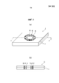
[0029] На Фиг.1a и 1b приведены виды, в общих чертах иллюстрирующие множество валиков, созданных при помощи способа лазерной сварки по настоящему изобретению, причем на Фиг.1a приведен общий вид и на Фиг.1b приведено поперечное сечение в плоскости А-А', показанной на Фиг.1a.[0029] FIGS. 1a and 1b are views generally illustrating a plurality of rollers created by the laser welding method of the present invention, wherein FIG. 1a is a general view and FIG. 1b is a cross-section in plane AA 'shown in Fig. 1a.
На Фиг.2 приведено примерное распределение твердости в сварном соединении, созданном при помощи способа лазерной сварки по настоящему изобретению.Figure 2 shows an exemplary hardness distribution in a weld created using the laser welding method of the present invention.
На Фиг.3а - Фиг.3е приведены виды, поясняющие то, как выглядит сварной валик в форме кольца.Figures 3a - 3e are views explaining what a ring-shaped weld bead looks like.
На Фиг.4 показано примерное обычное сварное соединение с множеством валиков в форме кольца.4 shows an exemplary conventional welded joint with a plurality of ring-shaped rollers.
На Фиг.5 показан пример лазерной сварки на фланце элемента в форме шляпы с использованием сварных валиков в форме кольца.Figure 5 shows an example of laser welding on the flange of a hat-shaped element using ring-shaped welds.
Описание вариантов реализации изобретенияDescription of the embodiments of the invention
[0030] Ниже со ссылкой на чертежи будут подробно рассмотрены варианты способа лазерной сварки по настоящему изобретению. Сначала будет рассмотрен основной режим сварки по настоящему изобретению для случая выполнения сварки с получением кругового сварного валика в форме кольца.[0030] Below with reference to the drawings, embodiments of the laser welding method of the present invention will be described in detail. First, the main welding mode of the present invention will be considered for the case of performing welding to obtain a circular welded bead in the form of a ring.
[0031] При использовании лазерной сварки для сварки наложенных друг на друга частей металлических листов 5, как показано на Фиг.5, сварку выполняют по кольцевой траектории, таким образом, чтобы получить сварные соединения, имеющие размеры сварных точек, создаваемых при электрической контактной сварке.[0031] When using laser welding to weld parts of
[0032] Согласно документу PLT 1, формируют первый валик 60, служащий основным сварным валиком, и с его внутренней стороны формируют второй валик 61 таким образом, чтобы он находился поблизости от первого валика 60 или перекрывался с ним, в результате чего получают множество валиков. При этом иногда во втором валике, который создан с внутренней стороны, возникает продольная трещина.[0032] According to
[0033] Авторы изобретения изучили причины этого путем осмотра разрушенных поверхностей, и в результате установили, что продольная трещина во втором валике представляет собой кристаллизационную трещину. Поэтому авторы изобретения дополнительно исследовали причины того, почему во внутреннем втором валике возникает трещина во время кристаллизации.[0033] The inventors studied the reasons for this by examining the destroyed surfaces, and as a result, it was found that the longitudinal crack in the second roll is a crystallization crack. Therefore, the inventors further investigated the reasons why a crack occurs in the inner second roller during crystallization.
[0034] В результате исследования, выполненного авторами изобретения, оказалось, что вероятность возникновения трещины во втором валике увеличивается с увеличением длины первого сварного валика в форме кольца, то есть, с увеличением диаметра валика в форме кольца. Кроме того, авторы изобретения поняли, что, если диаметр первого сварного валика является небольшим, или второй валик создается в области ближе к центру, трещины не возникает. На основе этих фактов, авторы предположили, что трещина вызвана следующим:[0034] As a result of the study performed by the inventors, it turned out that the likelihood of a crack in the second roll increases with the length of the first welded roll in the shape of a ring, that is, with an increase in the diameter of the roll in the shape of a ring. In addition, the inventors realized that if the diameter of the first weld bead is small or the second bead is created in an area closer to the center, no cracks occur. Based on these facts, the authors suggested that the crack was caused by the following:
[0035] При формировании первого валика, в области, окруженной этим валиком, в направлении, перпендикулярном линии сварки в плоскости, вертикальной к направлению по толщине листа, возникают растягивающие остаточные напряжения. Если вторую сварку выполняют в области, в которой возникают растягивающие остаточные напряжения, увеличивается воздействие на стальной лист в области, примыкающей к расплавленному валику, поэтому из-за растягивающих остаточных напряжений лист деформируется с растяжением расплавленного валика в направлении по ширине. По этой причине в середине процесса кристаллизации, до ее завершения, во втором сварном валике возникает трещина.[0035] When the first roller is formed, in the area surrounded by this roller, in a direction perpendicular to the welding line in a plane vertical to the direction along the sheet thickness , tensile residual stresses occur. If the second welding is performed in the region in which tensile residual stresses arise, the effect on the steel sheet in the region adjacent to the molten roller increases, therefore, due to tensile residual stresses, the sheet is deformed by stretching the molten roller in the width direction. For this reason, in the middle of the crystallization process, before its completion, a crack occurs in the second weld bead.
[0036] Поэтому авторы изобретения стали искать способ формирования второго валика, на который не влияют растягивающие остаточные напряжения, возникающие в направлении, перпендикулярном линии сварки в плоскости, вертикальной к направлению по толщине листа, в области, окруженной первым валиком. В результате они осознали, что путем последовательного формирования второго валика и дополнительных валиков не с внутренней, а с внешней стороны первого валика, можно сваривать листы, не допуская возникновения трещин во втором и последующих валиках.[0036] Therefore, the inventors began to look for a method of forming a second roller, which is not affected by tensile residual stresses arising in a direction perpendicular to the welding line in a plane vertical to the direction along the sheet thickness in the region surrounded by the first roller. As a result, they realized that by sequentially forming the second roller and additional rollers not from the inside, but from the outside of the first roller, it is possible to weld the sheets, preventing the occurrence of cracks in the second and subsequent rollers.
[0037] То есть, они выяснили, что, при формировании множества валиков, путем последовательного формирования сварных валиков в направлении изнутри наружу можно получать внешний валик 20, на который не влияют растягивающие остаточные напряжения, возникающие с внутренней стороны предыдущего валика и, таким образом, можно получать множество валиков без возникновения трещин.[0037] That is, they found that, when forming a plurality of rollers, by sequentially forming the welded rollers from the inside out, it is possible to obtain an
[0038] Настоящее изобретение создано после дополнительного изучения вариантов его реализации, в основе которых лежит такой указанный выше базовый принцип. Ниже со ссылкой на Фиг.1 будут рассмотрены требования и предпочтительные требования, предъявляемые настоящим изобретением.[0038] The present invention was created after further study of the options for its implementation, which are based on such the above basic principle. Below with reference to Figure 1 will be considered the requirements and preferred requirements of the present invention.
[0039] Формирование первого сварного валика [0039] Formation of the first weld bead
В настоящем изобретении друг на друга накладывают множество металлических листов 5 и направляют лазерный луч в запланированное место сварки на наложенных металлических листах, чтобы создать множество сварных валиков в форме кольца и, таким образом, сварить вместе наложенные металлические листы.In the present invention, a plurality of
[0040] При этом в настоящем изобретении сначала перемещают лазерный луч в заранее определенном месте, чтобы создать первый сварной валик 10, представляющий собой крайний изнутри валик. При задании областей сварки во множестве мест, например, как показано на Фиг.5, можно изготовить сварной конструктивный элемент, но здесь будет рассмотрено одно место сварки.[0040] In this case, in the present invention, the laser beam is first moved in a predetermined location to create a
[0041] Первый сварной валик 10, например, формируют с внешним диаметром 3-15 мм. Отметим, что форма созданного валика будет рассмотрена позднее, но форма сварного валика не ограничивается круговой, поэтому в настоящем изобретении в качестве внешнего диаметра будет задаваться максимальная длина отрезка прямой, соединяющего две точки на линии, соединяющей линии сплавления на внешних сторонах сварного валика (внешней границе сварного валика).[0041] The
[0042] Формирование второго валика и последующих сварных валиков [0042] Formation of the second roller and subsequent weld rollers
Далее лазерный луч перемещают в области с внешней стороны первого сварного валика 10, чтобы создать второй сварной валик 20 и следующий за ним сварной валик 30 последовательно в направлении изнутри наружу. Для получения требуемой прочности соединения число валиков, начиная со второго сварного валика 20, составляет два или более.Next, the laser beam is moved in the area on the outside of the
[0043] При применении настоящего изобретения, например, для сварки элемента конструкции автомобиля, крайний с внешней стороны сварной валик (крайний снаружи валик) имеет внешний диаметр 20 мм или менее. Причина заключается в том, что элементы конструкции автомобилей изготавливают меньшего веса. Ширина наложенных друг на друга частей, например, фланцев элементов, показанных на Фиг.5, также уменьшается. Кроме того, элементы сваривают при помощи лазера с большой скоростью путем дистанционной сварки.[0043] When applying the present invention, for example, for welding an automobile structural member, the outermost weld bead (outermost bead) has an outer diameter of 20 mm or less. The reason is that the structural elements of cars make less weight. The width of the superimposed parts, for example, the flanges of the elements shown in FIG. 5, also decreases. In addition, the elements are laser welded at high speed by remote welding.
[0044] Ширина сварного валика, созданного при помощи лазера, при том, что она зависит от используемого лазерного устройства, обычно составляет 0,5-1,5 мм. Число валиков, которые можно создать в одном месте выполнения сварки, может определяться в соответствии с областью применения сварного соединения и конкретным образом не ограничивается. При применении настоящего изобретения для сварки элемента конструкции автомобиля, если учитывать внешний диаметр и ширину крайнего снаружи валика, максимальное число валиков приблизительно равно 10.[0044] The width of the weld bead created using the laser, while it depends on the laser device used, is usually 0.5-1.5 mm. The number of rollers that can be created in one place of welding can be determined in accordance with the scope of the welded joint and is not specifically limited. When applying the present invention for welding a structural member of a vehicle, taking into account the outer diameter and width of the outermost roller, the maximum number of rollers is approximately 10.
[0045] Твердость сварных валиков (в описании, если не указано иное, указывается поверхностная твердость сварных валиков) [0045] Hardness of the welded rollers (unless otherwise specified, the surface hardness of the welded rollers is indicated in the description)
При формировании валиков таким образом, твердость внутреннего валика снижается, в результате чего твердость сварных валиков постепенно повышается в направлении наружу. Твердость сварных валиков определяют путем измерения твердости по Виккерсу в шести - восьми точках или около того в направлении по ширине сварного валика и нахождения среднего значения. Путем получения такого распределения твердости можно увеличить прочность соединения на срез при растяжении.When forming the rollers in this way, the hardness of the inner roller decreases, with the result that the hardness of the welded rollers gradually increases outward. The hardness of the welded rollers is determined by measuring the Vickers hardness at six to eight points or so in the direction along the width of the welded roller and finding the average value. By obtaining such a distribution of hardness, it is possible to increase the tensile strength of the joint.
[0046] На Фиг.2 приведен пример распределения твердости при использовании способа лазерной сварки по настоящему изобретению для формирования валиков в листах из стали класса 980 МПа при мощности лазера 4 кВт и скорости сварки 4 м/мин, концентрической формы и в порядке следования Ø8 мм, Ø16 мм и Ø20 мм, каждые 0,9 секунды. Поверхностная твердость сварных валиков (средние значения) составляет, в порядке следования от внутреннего валика, 274 HV, 289 HV и 356 HV. Понятно, что твердость повышается в направлении наружу.[0046] Figure 2 shows an example of the distribution of hardness using the laser welding method of the present invention to form rollers in sheets of steel of class 980 MPa with a laser power of 4 kW and a welding speed of 4 m / min, concentric in shape and in sequence of Ø8 mm , Ø16 mm and Ø20 mm, every 0.9 seconds. The surface hardness of the welded rollers (average values) is, in the order from the inner roller, 274 HV, 289 HV and 356 HV. It is understood that hardness rises outward.
[0047] Твердость сварных валиков конкретным образом не ограничивается, но, если твердость является слишком низкой, прочность сварного соединения в целом падает, поэтому предпочтительным является 200 HV или более, и более предпочтительным является 250 HV или более. Кроме того, если твердость является слишком высокой, в зоне сварки легко возникает трещина, поэтому предпочтительным является 700 HV или менее и более предпочтительным является 550 HV или менее.[0047] The hardness of the weld beads is not specifically limited, but if the hardness is too low, the strength of the weld generally decreases, therefore, 200 HV or more is preferable , and 250 HV or more is more preferable. Furthermore, if the hardness is too high, a crack easily occurs in the weld zone, therefore, 700 HV or less is preferable, and 550 HV or less is more preferable.
[0048] Расположение валиков [0048] Location of the rollers
При формировании множества сварных валиков используют (i) метод формирования сварных валиков таким образом, чтобы они не накладывались друг на друга, и (ii) метод формирования частично перекрывающихся внутреннего сварного валика и внешнего сварного валика. При использовании каждого из методов множество валиков увеличивает площадь соединения металлических листов, в результате чего можно дополнительно повысить прочность соединения.When forming a plurality of weld beads, use (i) a method of forming weld beads so that they do not overlap each other, and (ii) a method of forming partially overlapping inner weld beads and an external weld bead. When using each of the methods, a plurality of rollers increases the joint area of the metal sheets, as a result of which it is possible to further increase the bond strength.
[0049] При формировании сварных валиков с перекрыванием, если перекрываются крайний снаружи валик и валик внутри него, можно соединить два сварных валика и увеличить ширину крайнего снаружи валика. При приложении нагрузки механические напряжения становятся максимальными в крайнем снаружи валике, но путем увеличения ширины этого валика напряжения в его связанной части можно снизить, в результате чего можно дополнительно повысить прочность соединения металлических листов.[0049] When forming welded rollers with overlapping, if the outermost roller and the roller inside it overlap, two welded rollers can be joined and the width of the outermost roller can be increased. When a load is applied, mechanical stresses become maximum in the outermost roller, but by increasing the width of this roller, the stresses in its associated part can be reduced, as a result of which it is possible to further increase the bond strength of metal sheets.
[0050] Время формирования второго валика и последующих валиков [0050] Formation time of the second roller and subsequent rollers
Множество валиков можно создавать непрерывно при помощи дистанционной сварки. В предпочтительном случае формирование внешнего сварного валика начинают через 0,5 сек или более после окончания формирования внутреннего сварного валика.Many rollers can be created continuously using remote welding. In the preferred case, the formation of the outer weld bead is started after 0.5 seconds or more after the end of the formation of the inner weld bead.
[0051] Если прошло мало времени после формирования внутреннего сварного валика, и если начать формирование следующего, внешнего сварного валика, когда температура внутреннего сварного валика является высокой, твердость в широкой области рядом с зоной сварки уменьшается, поэтому прочность соединения падает. Не существует проблем, связанных с длительностью периода времени после формирования внутреннего сварного валика, но даже если этот период является большим, это не приносит особой выгоды, время такта увеличивается, и стоимость изготовления растет.[0051] If little time has passed after the formation of the internal weld bead, and if the formation of the next external weld bead is started, when the temperature of the internal weld bead is high, hardness in a wide area near the weld zone decreases, so the bond strength decreases. There are no problems associated with the length of time after the formation of the inner weld bead, but even if this period is large, it does not bring much benefit, the cycle time increases, and the manufacturing cost increases.
[0052] Например, если металлические листы представляют собой стальные листы, имеющие содержание С на уровне 0,65% или менее, предпочтительно на уровне 0,45% или менее, при задании периода времени (0,5 с или более) между одним сварным валиком и следующим, температура внутреннего сварного валика падает на 50°С или более от температуры Ms (температура начала мартенситного превращения), и до воздействия теплоты из-за формирования внешнего сварного валика во внутреннем сварном валике возникает количество мартенсита, необходимое для обеспечения прочности в зоне сварки. Кроме того, также и во внешнем сварном валике, воздействие теплоты от внутреннего сварного валика уменьшается, в результате чего возникает достаточное количество мартенсита.[0052] For example, if the metal sheets are steel sheets having a C content of 0.65% or less, preferably 0.45% or less, when a time period (0.5 s or more) is set between one welded and the next, the temperature of the internal weld bead drops by 50 ° С or more from the temperature Ms (the temperature of the onset of martensitic transformation), and before the action of heat due to the formation of the external weld bead in the internal weld bead, the amount of martensite necessary to provide strength in the weld zone. In addition, also in the external weld bead, the effect of heat from the internal weld bead is reduced, resulting in a sufficient amount of martensite.
[0053] Форма сварного валика [0053] Weld bead shape
В настоящем изобретении лазерная сварка используется для формирования сварного валика в форме кольца или разомкнутого кольца. "Сварной валик в форме кольца" означает валик с круговой, эллиптической, овальной или ломаной линией прохождения или такой валик с суженной частью, причем линия прохождения валика является непрерывной, и валик ограничивает конкретную площадь. Кроме того, "сварной валик в форме разомкнутого кольца" означает валик с круговой, эллиптической, овальной или ломаной линией прохождения или такой валик с суженной частью, причем линия прохождения валика имеет область прерывания, и валик и отрезок прямой, соединяющий части валика, ограничивают конкретную площадь.In the present invention, laser welding is used to form a ring or open ring weld bead. “Ring-shaped weld bead” means a bead with a circular, elliptical, oval or broken line or such a bead with a tapered portion, the bead being continuous, and the bead limits a specific area. In addition, “open-ring welded bead” means a bead with a circular, elliptical, oval or broken line or such a bead with a tapered part, the bead line having an interruption area, and the bead and straight line connecting the bead parts limit a particular area.
[0054] На Фиг.3a - Фиг.3е приведены примеры формы третьего сварного валика 30. Валики показаны сплошными линиями, а области 40 прерывания валиков показаны пунктирными линиями. Разумеется, области прерывания могут быть заменены валиками для получения непрерывных валиков. Из Фиг.3а - Фиг.3е, на Фиг.3а показан валик эллиптической формы, на Фиг.3b показан валик овальной формы, на Фиг.3c показан валик овальной формы с сужением, на Фиг.3d показан валик с ломаной линией прохождения и на Фиг.3е показан круговой валик.[0054] Figures 3a - 3e show examples of the shape of the
[0055] На Фиг.3а - Фиг.3е для упрощения изображен третий сварной валик 30, но используемые первый и второй сварные валики являются валиками с формой, в общем аналогичной форме третьего сварного валика. Кроме того, также и при формировании четвертого валика или еще одного сварного валика снаружи третьего сварного валика предпочтительны формы, аналогичные форме третьего сварного валика.[0055] Figures 3a - 3e show a
[0056] Сварной валик формируют с областью 40 прерывания, чтобы получить зазор между соединяемыми поверхностями стальных листов. Например, при наложении друг на друга и сварке оцинкованных стальных листов, температура цинкового покрытия между стальными листами достигает температуры кипения, и начинается его испарение, в результате чего происходит быстрое увеличение объема. Если отсутствует проход для пара или для выхода испаряющегося цинка в области, окруженной сварным валиком, давление между стальными листами растет, во время сварки в жидкой ванне возникает разбрызгивание, и в сварном валике возникают дефекты. По этой причине между соединяемыми поверхностями стальных листов формируют зазор, чтобы обеспечить сброс такого давления.[0056] A weld bead is formed with an
[0057] Ширина сварного валика [0057] Width of the weld bead
Ширина сварного валика должна быть такой, чтобы не возникало прожога, и обычно составляет 0,5-1,5 мм.The width of the weld bead should be such that no burn-through occurs, and is usually 0.5-1.5 mm.
[0058] Метод выполнения сварки [0058] Method for performing welding
В способе лазерной сварки по настоящему изобретению сварку можно выполнять во множестве мест сварки на фланцевой части элемента в форме шляпы и т.п. с использованием любого из методов: (i) метода последовательного формирования множества валиков в каждом месте полностью и (ii) метода непрерывного формирования первых сварных валиков во множестве мест со следующим за ним формированием вторых сварных валиков в тех местах, где были созданы первые сварные валики, и затем аналогичным формированием третьих сварных валиков и последующих сварных валиков.In the laser welding method of the present invention, welding can be performed at a plurality of welding spots on a flange portion of a hat-shaped member or the like. using any of the methods: (i) the method of sequentially forming a plurality of rollers in each place completely and (ii) the method of continuously forming the first weld rollers in many places followed by the formation of second weld rollers in the places where the first weld rollers were created, and then similarly forming the third weld beads and subsequent weld beads.
[0059] В частности, метод (ii) подходит в качестве метода, при выполнении которого ждут до тех пор, пока температура внутреннего сварного валика не станет меньше или равной температуре Ms - 50°С, после чего снаружи формируют второй и третий сварные валики.[0059] In particular, method (ii) is suitable as a method in which it is waited until the temperature of the internal weld bead is less than or equal to the temperature Ms -50 ° C, after which the second and third weld beads are formed outside.
[0060] При дистанционной лазерной сварке можно непрерывно выполнять сварку во множестве мест, например, на фланцевой части элемента в форме шляпы, с высокой скоростью. При такой сварке, в случае использования метода, в котором сварку выполняют по порядку в каждом месте полностью, например, формируют первый сварной валик, ждут до тех пор, пока температура первого сварного валика не станет меньше или равной температуре Ms - 50°С, после чего с внешней стороны формируют второй и третий сварные валики, общее время сварки удлиняется, и увеличивается время такта.[0060] In remote laser welding, it is possible to continuously perform welding in a plurality of locations, for example, on the flange portion of a hat-shaped member, at high speed. In such welding, in the case of using the method in which welding is carried out in order in each place completely, for example, the first weld bead is formed, wait until the temperature of the first weld bead is less than or equal to the temperature Ms - 50 ° С, after of which the second and third weld beads are formed from the outside, the total welding time is lengthened, and the cycle time is increased.
[0061] Чтобы избежать этого при формировании множества сварных валиков, можно эффективным образом использовать время ожидания перед формированием вторых сварных валиков путем применения дистанционной сварки, при которой используют зеркало для фокусирования оптической системы, изменяют положение лазерного пятна за очень короткое время и непрерывно формируют первые валики во множестве мест.[0061] In order to avoid this when forming a plurality of welded rollers, it is possible to effectively use the waiting time before forming the second welded rollers by using remote welding, which uses a mirror to focus the optical system, change the position of the laser spot in a very short time and continuously form the first rollers in many places.
[0062] То есть, в случае, если непрерывно формируют первые сварные валики во множестве мест, затем непрерывно формируют вторые сварные валики в тех местах, где средняя температура первого сварного валика стала меньше или равной температуре Ms - 50°С, и формируют третьи сварные валики при помощи дистанционной лазерной сварки таким же образом, что и вторые сварные валики в тех местах, где температуры вторых сварных валиков стали меньше или равными температуре Ms - 50°С, то время, когда нет облучения лазерным лучом из-за ожидания, становится короче, и в результате уменьшается общее время сварки.[0062] That is, in the case where the first weld beads are continuously formed in a plurality of places, then the second weld beads are continuously formed in those places where the average temperature of the first weld bead is less than or equal to the temperature Ms -50 ° C, and the third weld beads are formed beams using remote laser welding in the same way as the second weld beads in those places where the temperatures of the second weld beads have become less than or equal to the temperature Ms - 50 ° C, the time when there is no laser beam irradiation due to waiting becomes shorter , and This reduces the total time of welding.
[0063] Условия сварки [0063] Welding conditions
Удельную мощность лазера, используемого для формирования сварного соединения по настоящему изобретению, можно подходящим образом определить, исходя из материала и толщины свариваемых металлических листов.The specific power of the laser used to form the welded joint of the present invention can be appropriately determined based on the material and thickness of the welded metal sheets.
[0064] Для примера, при наложении друг на друга и сварке листов из высокопрочной стали толщиной 0,5-3,0 мм или около того удельная мощность лазера предпочтительно находится в диапазоне 0,5 МВт/см2-500 МВт/см2.[0064] For example, when superimposing and welding sheets of high strength steel with a thickness of 0.5-3.0 mm or so, the specific laser power is preferably in the range of 0.5 MW / cm 2-500 MW / cm 2 .
[0065] В случае этого примера, если удельная мощность составляет 0,5 МВт/см2 или более, становится возможной сварка с кинжальным проплавлением, при которой лазерный луч проходит через всю толщину листа. Кроме того, даже в диапазоне небольших скоростей сварки, в ранее созданном валике может выполняться термообработка путем формирования последующего валика. Если удельная мощность ниже 0,5 МВт/см2, кинжального проплавления не возникает, поэтому, чтобы обеспечить проплавление при сварке, необходимо значительно снизить скорость перемещения лазерного луча, то есть, скорость сварки, поэтому это является невыгодным в условиях реального производства. С другой стороны, если удельная мощность выше 500 МВт/см2, в области, облучаемой лазером, начинает преобладать испарение, поэтому применение его в качестве источника теплоты при сварке плавлением является невозможным, и формирование валика затрудняется.[0065] In the case of this example, if the specific power is 0.5 MW / cm 2 or more, dagger penetration welding is possible, in which the laser beam passes through the entire thickness of the sheet. In addition, even in the range of low welding speeds, heat treatment can be carried out in a previously created roller by forming a subsequent roller. If the specific power is below 0.5 MW / cm 2 , dagger penetration does not occur, therefore, in order to ensure penetration during welding, it is necessary to significantly reduce the speed of movement of the laser beam, that is, the welding speed, so this is disadvantageous in real production conditions. On the other hand, if the specific power is higher than 500 MW / cm 2 , evaporation begins to predominate in the region irradiated by the laser, so it is impossible to use it as a heat source in fusion welding, and the formation of the roller is difficult.
[0066] Металлические листы, используемые для получения сварного соединения при помощи лазерной сварки [0066] The metal sheets used to obtain a welded joint using laser welding
Металлические листы, используемые для получения при помощи лазерной сварки сварного соединения по настоящему изобретению, конкретным образом не ограничиваются. Однако, если толщина листа становится небольшой, хотя и обеспечивается повышение прочности в зоне сварки, прочность соединения определяется, главным образом, толщиной листа, поэтому эффект повышения прочности соединения в целом уменьшается. Даже если толщина листа становится большой, при помощи настоящего изобретения можно обеспечить повышение прочности в зоне сварки.The metal sheets used to produce a laser weld of the present invention are not particularly limited. However, if the sheet thickness becomes small, although an increase in strength in the weld zone is provided, the bond strength is determined mainly by the sheet thickness, therefore, the effect of increasing the bond strength generally decreases. Even if the sheet thickness becomes large, the present invention can provide increased strength in the weld zone.
[0067] Способ лазерной сварки по настоящему изобретению особенно подходит для сварки с наложением друг на друга листов из высокопрочной стали, имеющих толщину в диапазоне 0,5-3,0 мм, где эффективным образом обеспечивается повышение прочности соединения, и вес элемента уменьшается. Кроме того, в случае листов из высокопрочной стали, как рассмотрено выше, во время охлаждения после формирования сварного валика происходит мартенситное превращение, поэтому можно ожидать дополнительного повышения прочности соединения.[0067] The laser welding method of the present invention is particularly suitable for welding superimposed sheets of high strength steel having a thickness in the range of 0.5-3.0 mm, whereby an increase in the bond strength is effectively provided and the weight of the element is reduced. In addition, in the case of sheets of high-strength steel, as discussed above, martensitic transformation occurs during cooling after the formation of the weld bead, so an additional increase in the strength of the joint can be expected.
[0068] В настоящем изобретении, при использовании лазерной сварки для формирования множества сварных валиков в форме кольца или разомкнутого кольца описанным выше образом, можно изготовить сварное соединение, прочность которого дополнительно повышена, а также повышена коррозионная стойкость внутри валика.[0068] In the present invention, when using laser welding to form a plurality of ring or open ring welded beads in the manner described above, it is possible to produce a weld joint whose strength is further enhanced and also the corrosion resistance inside the bead is increased.
[0069] Отметим, что выше при описании изобретения была рассмотрена сварка листов из высокопрочной стали при изготовлении автомобиля, но настоящее изобретение этим не ограничивается. В качестве вариантов применения также становится возможным применение в элементах для других транспортных средств, элементах для бытовых электрических приборов, в строительных материалах, судах и т.д. Помимо этого, металлические листы также не ограничиваются листами из высокопрочной стали. Также можно использовать другую сталь, нержавеющую сталь, алюминиевый сплав, титановый сплав и т.д.[0069] Note that, above, in the description of the invention, welding of high-strength steel sheets in the manufacture of an automobile has been considered, but the present invention is not limited to this. As application options, it also becomes possible to use in elements for other vehicles, elements for household electrical appliances, in building materials, ships, etc. In addition, metal sheets are also not limited to high strength steel sheets. You can also use other steel, stainless steel, aluminum alloy, titanium alloy, etc.
[0070] Пример 1 [0070] Example 1
Чтобы получить сварное соединение, были наложены друг на друга и сварены при помощи лазерной сварки два листа из высокопрочной стали, содержащей в качестве основных компонентов 0,13% С; 0,9% Si; 2,2% Mn; 0,01% P и 0,004% S, с толщиной 1,0 мм. Помимо этого, аналогичным образом были получены соединение для листов из алюминиевого сплава А5083 (серия 5000) с толщиной 1,2 мм и соединение для листов из репрезентативного титанового сплава Ti-6%Al-4%V с толщиной 1,0 мм.To obtain a welded joint, two sheets of high-strength steel containing 0.13% C as the main components were superimposed and laser-welded. 0.9% Si; 2.2% Mn; 0.01% P and 0.004% S, with a thickness of 1.0 mm. In addition, a compound for sheets of aluminum alloy A5083 (5000 series) with a thickness of 1.2 mm and a compound for sheets of a representative titanium alloy Ti-6% Al-4% V with a thickness of 1.0 mm were similarly prepared.
[0071] Валики, созданные в зоне сварки, имели замкнутую круговую форму или формы, показанные на Фиг.3a - Фиг.3e. Были получены соединения, имеющие три или четыре сварных валика, а также соединение, имеющее только один валик.[0071] The rollers created in the weld zone had a closed circular shape or the shapes shown in Figs. 3a to 3e. Compounds having three or four weld beads were obtained, as well as a compound having only one bead.
[0072] Путем изменения формы или размеров сварных валиков, ширины валиков, положений формирования валиков и т.д., при помощи лазерной сварки было получено множество типов сварных соединений. В некоторых примерах крайний снаружи валик, находящийся на периферии, и валик с его внутренней стороны контактировали или были созданы с наложением друг на друга.[0072] By changing the shape or size of the weld beads, the width of the beads, the positions of the bead formation, etc., many types of welds have been obtained by laser welding. In some examples, the outermost roller located on the periphery and the roller on its inner side were in contact or were created overlapping one another.
[0073] Условия для случая стальных листов приведены в Таблице 1 и Таблицах с 2-1 по 2-5. Помимо этого, условия для случая алюминиевых листов приведены в Таблице 3 и Таблицах с 4-1 по 4-5, в то время как условия для случая титанового сплава приведены в Таблице 5 и Таблицах с 6-1 по 6-5. Ширина валиков в одном и том же месте выполнения сварки была одинаковой.[0073] The conditions for the case of steel sheets are shown in Table 1 and Tables 2-1 to 2-5. In addition, the conditions for the case of aluminum sheets are shown in Table 3 and Tables 4-1 to 4-5, while the conditions for the case of titanium alloy are shown in Table 5 and Tables 6-1 to 6-5. The width of the rollers at the same spot was the same.
[0074] Что касается внешнего диаметра зоны сварки, если форма сварного валика являлась круговой, за него принимался внешний диаметр, измеренный на внешней границе сварного валика на поверхности листа со стороны, облученной лазером, в то время как в случае форм, показанных на Фиг.3a - Фиг.3e, за внешний диаметр сварного валика принималась максимальная длина отрезка прямой, соединяющего две точки на линии, соединяющей линии сплавления на внешних сторонах сварного валика (внешней границе сварного валика), но в любом случае был обеспечен постоянный диаметр крайнего снаружи сварного валика, который был равен 20 мм.[0074] As for the outer diameter of the weld zone, if the shape of the weld bead was circular, it was taken to be the outer diameter measured at the outer border of the weld bead on the sheet surface from the side irradiated by the laser, while in the case of the shapes shown in FIG. 3a - Fig. 3e, for the outer diameter of the weld bead, the maximum length of the straight line connecting two points on the line connecting the fusion lines on the outer sides of the weld bead (the outer boundary of the weld bead) was taken, but in any case a constant the diameter of the outermost weld bead, which was 20 mm.
[0075] Отметим, что Таблица 1, Таблица 3 и Таблица 5 соответствуют случаю концентрического формирования валиков, в то время как формы сварных валиков в Таблицах с 2-1 по 2-5, Таблицах с 4-1 по 4-5 и Таблицах с 6-1 по 6-5 в указанном порядке соответствуют формам, показанным на Фиг.3a - Фиг.3e. Кроме того, в Таблицах с 1 по 6 подчеркиванием указан выход за пределы значений, установленных в настоящем изобретении.[0075] Note that Table 1, Table 3, and Table 5 correspond to the case of concentric formation of the rollers, while the shapes of the welded rollers in Tables 2-1 to 2-5, Tables 4-1 to 4-5, and Tables c 6-1 through 6-5 in the indicated order correspond to the shapes shown in Figs. 3a - 3e. In addition, Tables 1 through 6 underline indicate the excess of the values established in the present invention.
[0076] Что касается других условий сварки, то мощность лазера составляла 4,0 кВт, положение фокуса задавалось на поверхности верхнего стального листа, и диаметр пятна луча в положении фокуса задавался 0,5 мм. Кроме того, скорость сварки задавалась постоянной и равной 4 м/мин.[0076] As for other welding conditions, the laser power was 4.0 kW, the focus position was set on the surface of the upper steel sheet, and the beam spot diameter in the focus position was set to 0.5 mm. In addition, the welding speed was set constant and equal to 4 m / min.
[0077] Полученное при помощи лазерной сварки сварное соединение проверялось на наличие трещин с использованием рентгеновского исследования "на просвет", и для него измерялись прочность на срез при растяжении (TSS) и прочность на растяжение в поперечном направлении (CTS).[0077] The welded joint obtained by laser welding was checked for cracks using X-ray “clearance”, and shear tensile strength (TSS) and transverse tensile strength (CTS) were measured.
{0078] Метод измерений и форма соединения для испытания на срез при растяжении соответствовали стандарту JIS Z 3137, в части для сварных соединений, полученных при помощи точечной контактной сварки, при этом метод измерений и форма соединения для испытания на прочность при поперечном растяжении соответствовали стандарту JIS Z 3137. То есть, для полученных соединений были проведены испытания на растяжение с использованием заранее определенных держателей и постоянной скорости растяжения, равной 10 мм/мин. Максимальные нагрузки были определены как прочность на срез при растяжении и прочность на растяжение в поперечном направлении.{0078] The measurement method and the shape of the joint for tensile shear tests were in accordance with JIS Z 3137, in part for the welded joints produced by spot welding, the measurement method and the shape of the joint for transverse tensile strength tests were JIS Z 3137. That is, tensile tests were carried out for the compounds obtained using predetermined holders and a constant tensile speed of 10 mm / min. Maximum loads were defined as shear tensile strength and transverse tensile strength.
[0079] Для концентрических форм валика и форм, показанных на Фиг.3a - Фиг.3e, хорошей считалась только ситуация отсутствия трещин в валиках и обеспечения относительной прочности на растяжение в поперечном направлении, больше или равной 1,0, где за 1,0 принималась прочность в случае формирования только одного валика (стальные листы: №№ 5, 12, 18, 24, 30 и 36, алюминиевый сплав: №№ 43, 50, 56, 62, 68 и 74, титановый сплав: №№ 81, 88, 94, 100, 106 и 112). Ситуация, когда относительные прочности на растяжение в поперечном направлении были меньше 1,0, или в валиках имелись трещины, считалась плохой. Эти результаты приведены в Таблицах с 1 по 6.[0079] For the concentric forms of the roller and the forms shown in Figs. 3a - 3e, only the situation of the absence of cracks in the rollers and the provision of a relative tensile strength in the transverse direction greater than or equal to 1.0, where 1.0 strength was taken if only one roll was formed (steel sheets: No. 5, 12, 18, 24, 30 and 36, aluminum alloy: No. 43, 50, 56, 62, 68 and 74, titanium alloy: No. 81, 88, 94, 100, 106 and 112). The situation when the relative tensile strengths in the transverse direction were less than 1.0, or there were cracks in the rollers, was considered bad. These results are shown in Tables 1 to 6.
[0080] Таблица 1[0080] Table 1
сThe time from the 2nd to the formation of the 3rd,
from
с *The time from the 3rd to the formation of the 4th,
from *
сThe time from the 4th to the formation of the 5th,
from
* "Время от N0-го до формирования N1-го" означает время от окончания формирования N0-го валика до начала формирования N1-го валика* "Time from the N 0 th to the formation of the N 1 th" means the time from the end of the formation of the N 0 th roller to the beginning of the formation of the N 1 th roller
[0081] Таблица 2-1 [0081] Table 2-1
сThe time from the 2nd to the formation of the 3rd,
from
с *The time from the 3rd to the formation of the 4th,
from *
* "Время от N0-го до формирования N1-го" означает время от окончания формирования N0-го валика до начала формирования N1-го валика* "Time from the N 0 th to the formation of the N 1 th" means the time from the end of the formation of the N 0 th roller to the beginning of the formation of the N 1 th roller
[0082] Таблица 2-2 [0082] Table 2-2
сThe time from the 2nd to the formation of the 3rd,
from
с *The time from the 3rd to the formation of the 4th,
from *
* "Время от N0-го до формирования N1-го" означает время от окончания формирования N0-го валика до начала формирования N1-го валика* "Time from the N 0 th to the formation of the N 1 th" means the time from the end of the formation of the N 0 th roller to the beginning of the formation of the N 1 th roller
[0083] Таблица 2-3 [0083] Table 2-3
сThe time from the 2nd to the formation of the 3rd,
from
с *The time from the 3rd to the formation of the 4th,
from *
* "Время от N0-го до формирования N1-го" означает время от окончания формирования N0-го валика до начала формирования N1-го валика* "Time from the N 0 th to the formation of the N 1 th" means the time from the end of the formation of the N 0 th roller to the beginning of the formation of the N 1 th roller
[0084] Таблица 2-4 [0084] Table 2-4
сThe time from the 2nd to the formation of the 3rd,
from
с *The time from the 3rd to the formation of the 4th,
from *
* "Время от N0-го до формирования N1-го" означает время от окончания формирования N0-го валика до начала формирования N1-го валика* "Time from the N 0 th to the formation of the N 1 th" means the time from the end of the formation of the N 0 th roller to the beginning of the formation of the N 1 th roller
[0085] Таблица 2-5 [0085] Table 2-5
сThe time from the 2nd to the formation of the 3rd,
from
с *The time from the 3rd to the formation of the 4th,
from *
* "Время от N0-го до формирования N1-го" означает время от окончания формирования N0-го валика до начала формирования N1-го валика* "Time from the N 0 th to the formation of the N 1 th" means the time from the end of the formation of the N 0 th roller to the beginning of the formation of the N 1 th roller
[0086] Таблица 3 [0086] Table 3
сThe time from the 2nd to the formation of the 3rd,
from
с *The time from the 3rd to the formation of the 4th,
from *
сThe time from the 4th to the formation of the 5th,
from
* "Время от N0-го до формирования N1-го" означает время от окончания формирования N0-го валика до начала формирования N1-го валика* "Time from the N 0 th to the formation of the N 1 th" means the time from the end of the formation of the N 0 th roller to the beginning of the formation of the N 1 th roller
[0087] Таблица 4-1 [0087] Table 4-1
сThe time from the 2nd to the formation of the 3rd,
from
с *The time from the 3rd to the formation of the 4th,
from *
* "Время от N0-го до формирования N1-го" означает время от окончания формирования N0-го валика до начала формирования N1-го валика* "Time from the N 0 th to the formation of the N 1 th" means the time from the end of the formation of the N 0 th roller to the beginning of the formation of the N 1 th roller
[0088] Таблица 4-2 [0088] Table 4-2
сThe time from the 2nd to the formation of the 3rd,
from
с *The time from the 3rd to the formation of the 4th,
from *
* "Время от N0-го до формирования N1-го" означает время от окончания формирования N0-го валика до начала формирования N1-го валика* "Time from the N 0 th to the formation of the N 1 th" means the time from the end of the formation of the N 0 th roller to the beginning of the formation of the N 1 th roller
[0089] Таблица 4-3 [0089] Table 4-3
сThe time from the 2nd to the formation of the 3rd,
from
с *The time from the 3rd to the formation of the 4th,
from *
* "Время от N0-го до формирования N1-го" означает время от окончания формирования N0-го валика до начала формирования N1-го валика* "Time from the N 0 th to the formation of the N 1 th" means the time from the end of the formation of the N 0 th roller to the beginning of the formation of the N 1 th roller
[0090] Таблица 4-4 [0090] Table 4-4
сThe time from the 2nd to the formation of the 3rd,
from
с *The time from the 3rd to the formation of the 4th,
from *
* "Время от N0-го до формирования N1-го" означает время от окончания формирования N0-го валика до начала формирования N1-го валика* "Time from the N 0 th to the formation of the N 1 th" means the time from the end of the formation of the N 0 th roller to the beginning of the formation of the N 1 th roller
[0091] Таблица 4-5 [0091] Table 4-5
сThe time from the 2nd to the formation of the 3rd,
from
с *The time from the 3rd to the formation of the 4th,
from *
* "Время от N0-го до формирования N1-го" означает время от окончания формирования N0-го валика до начала формирования N1-го валика* "Time from the N 0 th to the formation of the N 1 th" means the time from the end of the formation of the N 0 th roller to the beginning of the formation of the N 1 th roller
[0092] Таблица 5 [0092] Table 5
сThe time from the 2nd to the formation of the 3rd,
from
с *The time from the 3rd to the formation of the 4th,
from *
сThe time from the 4th to the formation of the 5th,
from
* "Время от N0-го до формирования N1-го" означает время от окончания формирования N0-го валика до начала формирования N1-го валика* "Time from the N 0 th to the formation of the N 1 th" means the time from the end of the formation of the N 0 th roller to the beginning of the formation of the N 1 th roller
[0093] Таблица 6-1 [0093] Table 6-1
сThe time from the 2nd to the formation of the 3rd,
from
с *The time from the 3rd to the formation of the 4th,
from *
* "Время от N0-го до формирования N1-го" означает время от окончания формирования N0-го валика до начала формирования N1-го валика* "Time from the N 0 th to the formation of the N 1 th" means the time from the end of the formation of the N 0 th roller to the beginning of the formation of the N 1 th roller
[0095] Таблица 6-2 [0095] Table 6-2
сThe time from the 2nd to the formation of the 3rd,
from
с *The time from the 3rd to the formation of the 4th,
from *
* "Время от N0-го до формирования N1-го" означает время от окончания формирования N0-го валика до начала формирования N1-го валика* "Time from the N 0 th to the formation of the N 1 th" means the time from the end of the formation of the N 0 th roller to the beginning of the formation of the N 1 th roller
[0095] Таблица 6-3 [0095] Table 6-3
сThe time from the 2nd to the formation of the 3rd,
from
с *The time from the 3rd to the formation of the 4th,
from *
* "Время от N0-го до формирования N1-го" означает время от окончания формирования N0-го валика до начала формирования N1-го валика* "Time from the N 0 th to the formation of the N 1 th" means the time from the end of the formation of the N 0 th roller to the beginning of the formation of the N 1 th roller
[0096] Таблица 6-4 [0096] Table 6-4
сThe time from the 2nd to the formation of the 3rd,
from
с *The time from the 3rd to the formation of the 4th,
from *
* "Время от N0-го до формирования N1-го" означает время от окончания формирования N0-го валика до начала формирования N1-го валика* "Time from the N 0 th to the formation of the N 1 th" means the time from the end of the formation of the N 0 th roller to the beginning of the formation of the N 1 th roller
[0097] Таблица 6-5 [0097] Table 6-5
сThe time from the 2nd to the formation of the 3rd,
from
с *The time from the 3rd to the formation of the 4th,
from *
* "Время от N0-го до формирования N1-го" означает время от окончания формирования N0-го валика до начала формирования N1-го валика* "Time from the N 0 th to the formation of the N 1 th" means the time from the end of the formation of the N 0 th roller to the beginning of the formation of the N 1 th roller
[0098] Как будет понятно из результатов, приведенных в Таблицах с 1 по 6, согласно настоящему изобретению, при помощи лазерной сварки можно было получить сварные соединения, имеющие превосходную прочность, без возникновения в валиках трещин.[0098] As will be understood from the results shown in Tables 1 to 6 according to the present invention, laser welding could produce welded joints having excellent strength without causing cracks in the rollers.
[0099] В частности, что касается прочности на срез при растяжении, площадь соединения в виде сварных валиков между стальными листами увеличилась, поэтому наблюдалось существенное повышение прочности.[0099] In particular, with regard to shear tensile strength, the joint area in the form of welded rollers between the steel sheets has increased, so a substantial increase in strength has been observed.
[0100] Отметим, что в примерах изобретения, приведенных в Таблицах с 1 по 6, с №№ 2, 10, 16, 22, 28 и 34 для стальных листов, №№ 40, 48, 54, 60, 66 и 72 для алюминиевых сплавов и №№ 78, 86, 92, 98, 104 и 110 для титановых сплавов сварные валики, являющиеся крайними снаружи, и сварные валики с их внутренней стороны были созданы с частичным наложением друг на друга. Сварные валики в других примерах изобретения были созданы таким образом, что ни один из первых сварных валиков и сварных валиков, созданных с внешних сторон, не накладывались друг на друга.[0100] Note that in the examples of the invention shown in Tables 1 to 6, No. 2, 10, 16, 22, 28 and 34 for steel sheets, No. 40, 48, 54, 60, 66 and 72 for aluminum alloys and Nos. 78, 86, 92, 98, 104, and 110 for titanium alloys, welded beams that are outermost, and welded beams on their inner side were created with a partial overlap. The welded rollers in other examples of the invention were designed so that none of the first welded rollers and welded rollers created from the outside were superimposed on each other.
[0101] В отличие от этого, если требования настоящего изобретения не удовлетворяются, прочность соединения является плохой по сравнению с настоящим изобретением, или в валике возникают трещины.[0101] In contrast, if the requirements of the present invention are not satisfied, the bond strength is poor compared to the present invention, or cracks occur in the roller.
[0102] №№ 6-8, 13, 14, 19, 20, 25,26, 31, 32, 37 и 38 для стальных листов, №№ 44-46, 51, 52, 57, 58, 63, 64, 69, 70, 75 и 76 для алюминиевых сплавов и №№ 82-84, 89, 90, 95, 96, 101, 102, 107, 108, 113 и 114 для титановых сплавов представляют собой сравнительные примеры формирования сварных соединений с тремя или более валиками. Валики были созданы с внутренних сторон первых валиков, поэтому во втором и дополнительно созданных валиках возникли трещины. Если сравнивать с примерами изобретения, прочность на срез при растяжении значительно ухудшилась.[0102] No. 6-8, 13, 14, 19, 20, 25,26, 31, 32, 37 and 38 for steel sheets, No. 44-46, 51, 52, 57, 58, 63, 64, 69, 70, 75 and 76 for aluminum alloys and nos. 82-84, 89, 90, 95, 96, 101, 102, 107, 108, 113 and 114 for titanium alloys are comparative examples of the formation of welded joints with three or more rollers. The rollers were created from the inside of the first rollers, so cracks appeared in the second and additionally created rollers. Compared to the examples of the invention, the shear tensile strength has deteriorated significantly.
[0103] В частности, в №№ 7, 8, 19, 25, 32 и 38 при формировании валиков в стальных листах вторые валики создавались, когда температура первых валиков не упала в достаточной степени, поэтому в первом валике не возникало достаточного количества мартенсита, твердость сталей снижалась чрезмерным образом, и прочность на растяжение в поперечном направлении значительно падала.[0103] In particular, in Nos. 7, 8, 19, 25, 32 and 38, when the rollers were formed in the steel sheets, the second rollers were created when the temperature of the first rollers did not drop sufficiently, therefore, in the first roller, there was not enough martensite, the hardness of the steels decreased excessively and the tensile strength in the transverse direction dropped significantly.
[0104] Пример 2 [0104] Example 2
Помимо этого, авторы изобретения изучили прочность на срез при растяжении при ограничении внешнего диаметра валика, являющегося крайним снаружи, до 10 мм для сравнения настоящего изобретения и документа PLT 2 (Опубликованный японский патент № 2012-240086А), исходя из предположения наличия узких фланцевых частей при сварке стальных листов. Отметим, что в основе метода испытания на растяжение лежал метод Примера 1. В Таблице 7 приведены результаты при формировании 3 окружностей (№116) и 5 окружностей (№ 117) концентрическим образом в соответствии с документом PLT2, которые сравниваются на основе прочности на срез при растяжении со случаем формирования четырех валиков по настоящему изобретению концентрическим образом (4 окружности, № 115).In addition, the inventors studied shear tensile strength while limiting the outer diameter of the roller, which is the outermost, to 10 mm to compare the present invention and PLT 2 (Japanese Patent Publication No. 2012-240086A), based on the assumption of the presence of narrow flange parts when welding steel sheets. Note that the tensile test method was based on the method of Example 1. Table 7 shows the results when forming 3 circles (No. 116) and 5 circles (No. 117) in a concentric manner in accordance with PLT2, which are compared on the basis of shear strength at tensile with the case of the formation of the four rollers of the present invention in a concentric manner (4 circles, No. 115).
[0105] В случае 3 окружностей, первый валик задается как основной валик, второй валик задается как валик, обеспечивающий область сжатия, и третий валик задается как термообработанный валик вместо первого валика. В случае 5 окружностей, к случаю с 3 валиками добавлены дополнительные валики, четвертый валик задан как валик, обеспечивающий область сжатия, и пятый валик задан как термообработанный валик. Период от начала до окончания формирования валиков был задан таким образом, чтобы удовлетворялись требования изобретения. Ситуация, когда прочность полученного соединения на срез при растяжении была хуже эталона, считалась плохой.[0105] In the case of 3 circles, the first roller is defined as a main roller, the second roller is defined as a roller providing a compression region, and the third roller is defined as a heat-treated roller instead of the first roller. In the case of 5 circles, additional rollers are added to the case with 3 rollers, the fourth roller is defined as a roller providing a compression area, and the fifth roller is defined as a heat-treated roller. The period from the beginning to the end of the formation of the rollers was set so as to satisfy the requirements of the invention. The situation when the tensile strength of the obtained compound was worse than the standard was considered poor.
[0106] Ни в одном из сварных валиков, созданных в соответствии с настоящим изобретением и документом PLT 2, трещины не возникали, но в случае 3 окружностей прочность соединения была хуже, так как площадь соединения стальных листов была меньше, чем в настоящем изобретении. Кроме того, в случае 5 окружностей созданные сварные валики занимали ограниченную площадь, с фиксированными расстояниями между ними, поэтому уже созданный третий валик снова сваривался с пятым валиком, толщина сварного метала в направлении по толщине листа уменьшалась из-за разбрызгивания, и прочность соединения ухудшалась по сравнению с настоящим изобретением.[0106] None of the weld beads created in accordance with the present invention and
[0107] Таблица 7[0107] Table 7
* PLT2 - Опубликованный японский патент №2012-240086А* PLT2 - Japanese Published Patent No. 2012-240086A
Промышленная применимостьIndustrial applicability
[0108] Согласно настоящему изобретению, сварное соединение, полученное при помощи лазерной сварки, обладает более высокой прочностью, чем ранее, и его можно применять в элементах для автомобилей и элементах для других транспортных средств, элементах для бытовых электрических приборов, в строительных материалах, судах и т.д., поэтому промышленная применимость является великолепной.[0108] According to the present invention, the welded joint obtained by laser welding has a higher strength than before, and it can be used in elements for cars and elements for other vehicles, elements for household electrical appliances, in building materials, ships etc., therefore, industrial applicability is excellent.
Список ссылочных обозначенийReference List
[0109] 1 - Сварное соединение, полученное при помощи лазерной сварки[0109] 1 - Weld obtained by laser welding
5 - Металлические листы5 - Metal sheets
10 - Первый сварной валик10 - First weld bead
20 - Второй сварной валик20 - Second weld bead
30 - Третий сварной валик30 - Third weld bead
40 - Область прерывания валика40 - Area break roller
50 - Элемент в форме шляпы50 - Hat-shaped element
50а - Фланцевая часть элемента в форме шляпы50a - Flange portion of the hat-shaped element
51 - Сварной валик51 - Welded roller
60 - Первый сварной валик при известном уровне техники60 - The first weld bead in the prior art
61 - Второй сварной валик при известном уровне техники61 - The second weld bead in the prior art
Claims (11)
Applications Claiming Priority (3)
| Application Number | Priority Date | Filing Date | Title |
|---|---|---|---|
| JP2014191806 | 2014-09-19 | ||
| JP2014-191806 | 2014-09-19 | ||
| PCT/JP2015/076528 WO2016043278A1 (en) | 2014-09-19 | 2015-09-17 | Laser welded joint and laser welding method |
Publications (3)
| Publication Number | Publication Date |
|---|---|
| RU2017113084A3 RU2017113084A3 (en) | 2018-10-19 |
| RU2017113084A RU2017113084A (en) | 2018-10-19 |
| RU2682193C2 true RU2682193C2 (en) | 2019-03-15 |
Family
ID=55533314
Family Applications (1)
| Application Number | Title | Priority Date | Filing Date |
|---|---|---|---|
| RU2017113084A RU2682193C2 (en) | 2014-09-19 | 2015-09-17 | Welded joint produced with laser welding and laser welding method |
Country Status (10)
| Country | Link |
|---|---|
| US (1) | US10722976B2 (en) |
| EP (1) | EP3195973B1 (en) |
| JP (1) | JP6690540B2 (en) |
| KR (1) | KR102057551B1 (en) |
| CN (1) | CN106715035B (en) |
| BR (1) | BR112017005084A2 (en) |
| CA (1) | CA2960753A1 (en) |
| MX (1) | MX2017003567A (en) |
| RU (1) | RU2682193C2 (en) |
| WO (1) | WO2016043278A1 (en) |
Cited By (1)
| Publication number | Priority date | Publication date | Assignee | Title |
|---|---|---|---|---|
| RU2775635C1 (en) * | 2020-03-23 | 2022-07-05 | Кабусики Кайся Тосиба | Monitoring and measuring apparatus and welding apparatus |
Families Citing this family (13)
| Publication number | Priority date | Publication date | Assignee | Title |
|---|---|---|---|---|
| WO2018145222A1 (en) * | 2017-02-09 | 2018-08-16 | GM Global Technology Operations LLC | Method for laser welding light metal workpieces that include a surface oxide coating |
| DE112017007470T5 (en) | 2017-06-13 | 2020-01-02 | GM Global Technology Operations LLC | METHOD FOR LASER WELDING WORKPIECES FROM METAL USING A COMBINATION OF WELDING MACHINES |
| WO2019162726A1 (en) * | 2018-02-24 | 2019-08-29 | Secretary, Department Of Atomic Energy | An improved laser welding method for enhanced weld quality and enhanced surface smoothness |
| CN109465546A (en) * | 2018-02-27 | 2019-03-15 | 深圳市艾雷激光科技有限公司 | Open loop method for laser welding |
| JP7036651B2 (en) * | 2018-04-05 | 2022-03-15 | トヨタ自動車株式会社 | Welding method |
| JP2019188407A (en) * | 2018-04-19 | 2019-10-31 | 株式会社神戸製鋼所 | Laser welded joint and method for production thereof |
| JP7063083B2 (en) * | 2018-04-25 | 2022-05-09 | トヨタ自動車株式会社 | Laser welding method |
| US11203085B2 (en) | 2018-09-25 | 2021-12-21 | GM Global Technology Operations LLC | Method and apparatus for laser welding |
| JP7097282B2 (en) * | 2018-11-22 | 2022-07-07 | 日立造船株式会社 | Butt welding method for extra-thick plates and butt welding equipment for extra-thick plates |
| CN113573838B (en) * | 2019-03-28 | 2023-06-02 | 杰富意钢铁株式会社 | Overlap laser welded joint, method for producing same, and structural member for automobile body |
| CN111014363B (en) * | 2019-12-25 | 2022-06-17 | 天水锻压机床(集团)有限公司 | Double-layer combined type stand column of large bending machine and preparation method thereof |
| CN114512572B (en) * | 2022-02-18 | 2024-03-29 | 深圳赛能数字能源技术有限公司 | Solder strip prefabricated part and production method thereof, solder strip and production method thereof |
| CN115352592A (en) * | 2022-07-29 | 2022-11-18 | 沪东中华造船(集团)有限公司 | Method for installing radar bulk pipe on LNG ship |
Citations (8)
| Publication number | Priority date | Publication date | Assignee | Title |
|---|---|---|---|---|
| RU2024378C1 (en) * | 1991-07-25 | 1994-12-15 | Институт проблем сверхпластичности металлов РАН | Method of manufacturing multilayer panels |
| RU2291771C1 (en) * | 2005-09-07 | 2007-01-20 | Василий Савельевич Юркин | Method for making high-strength laminate metallic tubes with layers of easy-to-melt metals |
| RU2309826C1 (en) * | 2006-04-03 | 2007-11-10 | Открытое акционерное общество Научно-производственное объединение "Поволжский авиационный технологический институт" | Method for making laminate metallic honeycomb panels and apparatus for performing the same |
| RU2373059C2 (en) * | 2004-01-13 | 2009-11-20 | Федерал-Могал Корпорейшн | Composite padding and method of its fabrication |
| RU2389591C2 (en) * | 2004-11-11 | 2010-05-20 | Сименс Акциенгезелльшафт | Method of jointing by local cold butt joint, including riveting, bolting and laser welding |
| WO2012050097A1 (en) * | 2010-10-12 | 2012-04-19 | 新日本製鐵株式会社 | Laser welding method |
| JP2012240086A (en) * | 2011-05-19 | 2012-12-10 | Nippon Steel Corp | Laser welding joint excellent in joint strength and method for manufacturing the same |
| CN103769746A (en) * | 2013-12-30 | 2014-05-07 | 华中科技大学 | Pulsed high magnetic field auxiliary laser welding method and device |
Family Cites Families (10)
| Publication number | Priority date | Publication date | Assignee | Title |
|---|---|---|---|---|
| JP3763525B2 (en) * | 2002-03-29 | 2006-04-05 | 本田技研工業株式会社 | Welding method and welding apparatus |
| JP2007000888A (en) * | 2005-06-22 | 2007-01-11 | Nisshin Steel Co Ltd | Laser welding method |
| JP4968201B2 (en) * | 2008-07-04 | 2012-07-04 | 住友金属工業株式会社 | Laser welded structural member and manufacturing method thereof |
| CN101676060B (en) * | 2008-09-19 | 2012-03-07 | 湖北中航精机科技股份有限公司 | Method for welding plate material of seat of vehicle by laser |
| JP5129717B2 (en) | 2008-10-15 | 2013-01-30 | 東亜工業株式会社 | Laser welding method for metal plated plate |
| JP5527526B2 (en) * | 2010-02-24 | 2014-06-18 | マツダ株式会社 | Laser welding method |
| JP5609595B2 (en) | 2010-12-01 | 2014-10-22 | トヨタ自動車株式会社 | Laser welding method |
| JP2014004801A (en) * | 2012-06-27 | 2014-01-16 | Shin Kobe Electric Mach Co Ltd | Resin molded product obtained by integrating metal member and method for manufacturing the same |
| JP2014004619A (en) * | 2012-06-27 | 2014-01-16 | Panasonic Corp | Laser joining method and joining component |
| JP5364856B1 (en) * | 2013-02-27 | 2013-12-11 | 三菱重工業株式会社 | Processing device, processing method |
-
2015
- 2015-09-17 KR KR1020177006721A patent/KR102057551B1/en active IP Right Grant
- 2015-09-17 EP EP15841515.8A patent/EP3195973B1/en active Active
- 2015-09-17 JP JP2016548948A patent/JP6690540B2/en active Active
- 2015-09-17 CN CN201580050206.8A patent/CN106715035B/en active Active
- 2015-09-17 RU RU2017113084A patent/RU2682193C2/en not_active IP Right Cessation
- 2015-09-17 MX MX2017003567A patent/MX2017003567A/en unknown
- 2015-09-17 US US15/512,175 patent/US10722976B2/en active Active
- 2015-09-17 CA CA2960753A patent/CA2960753A1/en not_active Abandoned
- 2015-09-17 WO PCT/JP2015/076528 patent/WO2016043278A1/en active Application Filing
- 2015-09-17 BR BR112017005084A patent/BR112017005084A2/en active Search and Examination
Patent Citations (8)
| Publication number | Priority date | Publication date | Assignee | Title |
|---|---|---|---|---|
| RU2024378C1 (en) * | 1991-07-25 | 1994-12-15 | Институт проблем сверхпластичности металлов РАН | Method of manufacturing multilayer panels |
| RU2373059C2 (en) * | 2004-01-13 | 2009-11-20 | Федерал-Могал Корпорейшн | Composite padding and method of its fabrication |
| RU2389591C2 (en) * | 2004-11-11 | 2010-05-20 | Сименс Акциенгезелльшафт | Method of jointing by local cold butt joint, including riveting, bolting and laser welding |
| RU2291771C1 (en) * | 2005-09-07 | 2007-01-20 | Василий Савельевич Юркин | Method for making high-strength laminate metallic tubes with layers of easy-to-melt metals |
| RU2309826C1 (en) * | 2006-04-03 | 2007-11-10 | Открытое акционерное общество Научно-производственное объединение "Поволжский авиационный технологический институт" | Method for making laminate metallic honeycomb panels and apparatus for performing the same |
| WO2012050097A1 (en) * | 2010-10-12 | 2012-04-19 | 新日本製鐵株式会社 | Laser welding method |
| JP2012240086A (en) * | 2011-05-19 | 2012-12-10 | Nippon Steel Corp | Laser welding joint excellent in joint strength and method for manufacturing the same |
| CN103769746A (en) * | 2013-12-30 | 2014-05-07 | 华中科技大学 | Pulsed high magnetic field auxiliary laser welding method and device |
Cited By (1)
| Publication number | Priority date | Publication date | Assignee | Title |
|---|---|---|---|---|
| RU2775635C1 (en) * | 2020-03-23 | 2022-07-05 | Кабусики Кайся Тосиба | Monitoring and measuring apparatus and welding apparatus |
Also Published As
| Publication number | Publication date |
|---|---|
| CA2960753A1 (en) | 2016-03-24 |
| JPWO2016043278A1 (en) | 2017-06-22 |
| KR20170038931A (en) | 2017-04-07 |
| JP6690540B2 (en) | 2020-04-28 |
| EP3195973A4 (en) | 2018-07-11 |
| EP3195973B1 (en) | 2022-05-11 |
| RU2017113084A3 (en) | 2018-10-19 |
| CN106715035B (en) | 2019-07-30 |
| CN106715035A (en) | 2017-05-24 |
| US20170274473A1 (en) | 2017-09-28 |
| EP3195973A1 (en) | 2017-07-26 |
| US10722976B2 (en) | 2020-07-28 |
| BR112017005084A2 (en) | 2017-12-05 |
| RU2017113084A (en) | 2018-10-19 |
| WO2016043278A1 (en) | 2016-03-24 |
| MX2017003567A (en) | 2017-07-14 |
| KR102057551B1 (en) | 2019-12-19 |
Similar Documents
| Publication | Publication Date | Title |
|---|---|---|
| RU2682193C2 (en) | Welded joint produced with laser welding and laser welding method | |
| RU2653742C2 (en) | Lap welding method, lap joint, production method of lap joint and an automobile part | |
| RU2685928C2 (en) | Method of point welding | |
| JP5130499B2 (en) | Laser welding method | |
| KR101653077B1 (en) | Welded structure with at least three laser welded nuggets arranged along a virtual closed curve, and corresponding laser welding method | |
| US9737955B2 (en) | Welded joint manufactured by method of resistance spot welding | |
| RU2689829C1 (en) | Method of welding of overlapping steel sheet and unit obtained by welding of overlapping steel sheet | |
| JPWO2016189855A1 (en) | Laser welding method | |
| JP6443319B2 (en) | Lap laser spot welded joint and method of manufacturing the welded joint | |
| KR102057893B1 (en) | Spot welding method | |
| EP2954969B1 (en) | Multi-electrode electrogas arc welding method for thick steel plates and multi-electrode electrogas arc circumferential welding method for steel pipes | |
| JP5730139B2 (en) | Butt welding method for steel | |
| EP3213862B1 (en) | Method of laser weldinng | |
| JP2017052006A (en) | Lap joint coupler and method for manufacturing same | |
| WO2020241500A1 (en) | Spot welded joint, and method for manufacturing spot welded joint | |
| JP6798359B2 (en) | Laminated joint and its manufacturing method | |
| Gerhards et al. | Laser beam welding of press hardened ultra-high strength 22MnB5 steel | |
| JP6866691B2 (en) | Laminated joint and its manufacturing method | |
| JP2010253509A (en) | Arc welding method | |
| JP2017052005A (en) | Lap joint coupler and method for manufacturing same | |
| JP7151762B2 (en) | SPOT WELD JOINTS, MOTOR VEHICLE STRUCTURE COMPONENTS WITH SPOT WELD JOINTS, AND METHOD FOR MANUFACTURING THE SPOT WELD JOINTS |
Legal Events
| Date | Code | Title | Description |
|---|---|---|---|
| PD4A | Correction of name of patent owner | ||
| MM4A | The patent is invalid due to non-payment of fees |
Effective date: 20200918 |