RU2681604C2 - Steam iron - Google Patents
Steam iron Download PDFInfo
- Publication number
- RU2681604C2 RU2681604C2 RU2017109876A RU2017109876A RU2681604C2 RU 2681604 C2 RU2681604 C2 RU 2681604C2 RU 2017109876 A RU2017109876 A RU 2017109876A RU 2017109876 A RU2017109876 A RU 2017109876A RU 2681604 C2 RU2681604 C2 RU 2681604C2
- Authority
- RU
- Russia
- Prior art keywords
- steam
- inlet
- iron
- channel
- water
- Prior art date
Links
- XEEYBQQBJWHFJM-UHFFFAOYSA-N Iron Chemical compound [Fe] XEEYBQQBJWHFJM-UHFFFAOYSA-N 0.000 title claims abstract description 195
- 229910052742 iron Inorganic materials 0.000 title claims abstract description 90
- XLYOFNOQVPJJNP-UHFFFAOYSA-N water Substances O XLYOFNOQVPJJNP-UHFFFAOYSA-N 0.000 claims abstract description 86
- 238000001704 evaporation Methods 0.000 claims abstract description 57
- 230000008020 evaporation Effects 0.000 claims abstract description 56
- 238000010438 heat treatment Methods 0.000 claims abstract description 34
- 230000000694 effects Effects 0.000 claims abstract description 17
- 235000000396 iron Nutrition 0.000 abstract description 10
- 238000010409 ironing Methods 0.000 abstract description 6
- 238000011144 upstream manufacturing Methods 0.000 abstract description 5
- 239000000126 substance Substances 0.000 abstract 1
- 238000000034 method Methods 0.000 description 6
- 238000010521 absorption reaction Methods 0.000 description 3
- 238000013461 design Methods 0.000 description 3
- XLYOFNOQVPJJNP-ZSJDYOACSA-N Heavy water Chemical compound [2H]O[2H] XLYOFNOQVPJJNP-ZSJDYOACSA-N 0.000 description 2
- 239000012530 fluid Substances 0.000 description 2
- 239000007788 liquid Substances 0.000 description 2
- 230000001105 regulatory effect Effects 0.000 description 2
- 238000000926 separation method Methods 0.000 description 2
- 230000015572 biosynthetic process Effects 0.000 description 1
- 238000006243 chemical reaction Methods 0.000 description 1
- 238000004891 communication Methods 0.000 description 1
- 230000001419 dependent effect Effects 0.000 description 1
- 238000005485 electric heating Methods 0.000 description 1
- 238000004134 energy conservation Methods 0.000 description 1
- 238000005265 energy consumption Methods 0.000 description 1
- DNHVXYDGZKWYNU-UHFFFAOYSA-N lead;hydrate Chemical compound O.[Pb] DNHVXYDGZKWYNU-UHFFFAOYSA-N 0.000 description 1
- 230000007774 longterm Effects 0.000 description 1
- 239000002184 metal Substances 0.000 description 1
- 229910052751 metal Inorganic materials 0.000 description 1
- 238000012545 processing Methods 0.000 description 1
- 230000002035 prolonged effect Effects 0.000 description 1
- 230000001681 protective effect Effects 0.000 description 1
- 238000003303 reheating Methods 0.000 description 1
- 239000007921 spray Substances 0.000 description 1
- 238000010025 steaming Methods 0.000 description 1
- 238000012546 transfer Methods 0.000 description 1
- 230000037303 wrinkles Effects 0.000 description 1
Images
Classifications
-
- D—TEXTILES; PAPER
- D06—TREATMENT OF TEXTILES OR THE LIKE; LAUNDERING; FLEXIBLE MATERIALS NOT OTHERWISE PROVIDED FOR
- D06F—LAUNDERING, DRYING, IRONING, PRESSING OR FOLDING TEXTILE ARTICLES
- D06F75/00—Hand irons
- D06F75/08—Hand irons internally heated by electricity
- D06F75/10—Hand irons internally heated by electricity with means for supplying steam to the article being ironed
- D06F75/12—Hand irons internally heated by electricity with means for supplying steam to the article being ironed the steam being produced from water supplied to the iron from an external source
Landscapes
- Engineering & Computer Science (AREA)
- Textile Engineering (AREA)
- Health & Medical Sciences (AREA)
- Public Health (AREA)
- Irons (AREA)
- Separating Particles In Gases By Inertia (AREA)
- Production Of Liquid Hydrocarbon Mixture For Refining Petroleum (AREA)
Abstract
Description
Область техники, к которой относится изобретениеFIELD OF THE INVENTION
Настоящее изобретение относится к паровому утюгу и, более конкретно, к паровому утюгу с усовершенствованным средством обработки пара для обеспечения более легкой конструкции по сравнению с известными паровыми утюгами.The present invention relates to a steam iron and, more particularly, to a steam iron with an improved steam treatment means to provide a lighter structure compared to known steam irons.
Предпосылки изобретенияBACKGROUND OF THE INVENTION
Утюг с генератором сжатого пара является паровым утюгом с высокой паропроизводительностью. Пар обычно генерируется в отдельном парогенераторе, расположенном в подставке вдали от утюга. Шланг, соединяющий парогенератор и утюг, подает пар в утюг после приведения в действие электроклапана, приводимого в действие кнопкой, приводимой в действие пользователем, на утюге. Однако, относительно холодный шланг, соединяющий парогенератор и утюг, особенно во время начального пуска устройства, вызывает конденсацию пара на внутреннюю стенку шланга во время подачи. Это приводит к подаче нежелательного количества жидкой воды в утюг вместе с паром, который может вызвать разбрызгивание воды из утюга.Iron with a compressed steam generator is a steam iron with high steam capacity. Steam is usually generated in a separate steam generator located in a stand away from the iron. The hose connecting the steam generator and the iron delivers steam to the iron after actuating the electrovalve, actuated by a button actuated by the user, on the iron. However, the relatively cold hose connecting the steam generator and the iron, especially during the initial start-up of the device, causes steam to condense onto the inner wall of the hose during feeding. This causes an undesirable amount of liquid water to be supplied to the iron along with steam, which can cause water to spray from the iron.
Известные утюги с генератором сжатого пара могут включать в себя подошву с высокой теплоемкостью с одним или более встроенными нагревательными элементами, которые сохраняют достаточно энергии для повторного испарения конденсата, подаваемого через шланг из парогенератора. В дополнении к этой необходимой тепловой массе подошвы мощность нагревательного элемента (нагревательных элементов) должна быть достаточной для повторного нагрева подошвы до предварительно установленной температуры, и такие нагревательные элементы могут иметь мощность около 800 Вт. Следовательно, масса подошвы является большой и является основным показателем всего веса утюга. Полученный в результате тяжелый утюг делает длительное использование утомительным и также делает трудным вертикальную глажку/отпаривание.Known flat steam generator irons may include a high heat-resistant sole with one or more built-in heating elements that store enough energy to re-evaporate the condensate supplied through the hose from the steam generator. In addition to this necessary thermal mass of the sole, the power of the heating element (s) should be sufficient to reheat the sole to a predetermined temperature, and such heating elements may have a power of about 800 watts. Therefore, the mass of the sole is large and is the main indicator of the total weight of the iron. The resulting heavy iron makes prolonged use tiring and also makes vertical ironing / steaming difficult.
Альтернативный известный способ предотвращения разбрызгивания, обусловленный конденсатом, образованным в шланге парового утюга, состоит в использовании сепаратора для отделения воды от пара. Такое устройство описано в WO/1999/025915A1. Однако, этот тип решения требует дополнительного средства для обработки отделенной воды и, таким образом, не обеспечивает более легкий утюг, поскольку дополнительные части средства для отделения воды приводят к дополнительному весу. Кроме того, некоторые известные утюги включают в себя систему возврата воды для подачи конденсата обратно в емкость в подставке. Однако, шнур, соединяющий утюг с подставкой, следовательно, требует два шланга (для подачи пара в утюг и возврата воды в подставку), что означает, что шнур шланга является жестким и тяжелым, ограничивая перемещение утюга во время глажки и уменьшая общую маневренность утюга.An alternative known method for preventing splashing caused by condensate formed in a steam iron hose is to use a separator to separate the water from the steam. Such a device is described in WO / 1999 / 025915A1. However, this type of solution requires additional means for treating the separated water, and thus does not provide a lighter iron, since additional parts of the means for separating water lead to additional weight. In addition, some well-known irons include a water return system for supplying condensate back to a container in a stand. However, the cord connecting the iron to the stand therefore requires two hoses (for supplying steam to the iron and returning water to the stand), which means that the hose cord is stiff and heavy, restricting the movement of the iron during ironing and reducing the overall maneuverability of the iron.
В рамках ст. 54(3) Европейской патентной конвенции известно из EP2808439 (поданный 6 марта 2014 г., опубликованный 3 декабря 2014 г.) как создать паровой утюг, содержащий подошву, нагревательный элемент для нагрева подошвы, входное соединение, содержащее первый входной канал для вмещения входного пара из парогенератора, и второй входной канал, сепаратор для отделения воды от пара, соединенный с входным соединением для вмещения пара из входного соединения и отделения пара от конденсата, переносимого паром, испарительную камеру, соединенную с сепаратором для отделения воды от пара для вмещения конденсата из сепаратора для отделения воды от пара и включающую в себя поверхность, нагреваемую упомянутым нагревательным элементом, для генерации выпаренной воды из упомянутого конденсата, причем испарительная камера соединена со вторым входным каналом, причем входное соединение содержит насадку с эффектом Вентури для выпуска упомянутого входного пара и создания пониженного давления в области второго входного канала для всасывания упомянутой выпаренной воды во входное соединение.Under Art. 54 (3) of the European Patent Convention, it is known from EP2808439 (filed March 6, 2014, published December 3, 2014) how to create a steam iron containing a sole, a heating element for heating the sole, an inlet connection containing a first inlet channel for receiving inlet steam from a steam generator, and a second inlet channel, a separator for separating water from steam, connected to an inlet connection for receiving steam from an inlet connection and separating steam from condensate carried by the steam, an evaporation chamber connected to a separator for water from steam for receiving condensate from a separator for separating water from steam and including a surface heated by said heating element for generating evaporated water from said condensate, wherein the evaporation chamber is connected to a second inlet channel, the inlet connection comprising a nozzle with a Venturi effect for releasing said inlet steam and creating a reduced pressure in the region of the second inlet channel for suctioning said evaporated water into the inlet connection.
Краткое описание настоящего изобретенияA brief description of the present invention
Целью настоящего изобретения является создание парового утюга с конфигурацией, которая обеспечивает более легкий паровой утюг, чем известные паровые утюги.An object of the present invention is to provide a steam iron with a configuration that provides a lighter steam iron than conventional steam irons.
Настоящее изобретение определено независимыми пунктами формулы изобретения. Зависимые пункты формулы изобретения определяют преимущественные варианты осуществления.The present invention is defined by the independent claims. The dependent claims define advantageous embodiments.
В соответствии с настоящим изобретением описан паровой утюг, содержащий подошву, нагревательный элемент для нагрева подошвы, входное соединение, содержащее первый входной канал для вмещения входного пара из парогенератора и второй входной канал, сепаратор для отделения воды от пара, соединенный с входным соединением, для вмещения пара из входного соединения и отделения пара от конденсата, переносимого паром, испарительную камеру, соединенную с сепаратором для отделения воды от пара, для вмещения конденсата из сепаратора для отделения воды от пара и включающую в себя поверхность, нагреваемую упомянутым нагревательным элементом, для генерации выпаренной воды из упомянутого конденсата, причем испарительная камера соединена со вторым входным каналом, причем входное соединение содержит насадку с эффектом Вентури для выпуска упомянутого входного пара и для генерации пониженного давления в области второго входного канала для всасывания упомянутой выпаренной воды во входное соединение, причем насадка с эффектом Вентури расположена в наружной трубке входного соединения, и второй входной канал расположен вверх по потоку от конца насадки Вентури, из которого выпускается входной пар, относительно направления потока пара.In accordance with the present invention, a steam iron is described comprising a sole, a heating element for heating the sole, an inlet connection comprising a first inlet channel for receiving the inlet steam from the steam generator and a second inlet channel, a separator for separating water from the steam connected to the inlet connection for holding steam from the inlet connection and the separation of steam from the condensate carried by the steam, an evaporation chamber connected to a separator for separating water from the steam, for receiving condensate from the separator to separate into odes from steam and including a surface heated by said heating element to generate evaporated water from said condensate, wherein the evaporation chamber is connected to a second inlet channel, the inlet connection comprising a nozzle with a venturi effect for releasing said inlet vapor and for generating reduced pressure in the area of the second inlet channel for suction of the aforementioned evaporated water into the inlet connection, and the nozzle with a Venturi effect is located in the outer tube of the inlet connection, second inlet passage located upstream of the end of the venturi nozzle, which is discharged from the inlet steam relative to the direction of steam flow.
Это преимущественно обеспечивает то, что второй входной канал расположен в области низкого давления во входном соединении для способствования эффективному всасыванию выпаренной воды из испарительной камеры через испарительную камеру во входное соединение.This advantageously ensures that the second inlet channel is located in the low pressure region of the inlet connection to facilitate efficient absorption of the evaporated water from the evaporation chamber through the evaporation chamber into the inlet connection.
Входная трубка может соединять по текучей среде выходной канал выходной трубки с входным каналом сепаратора для отделения воды от пара, и площадь поперечного сечения каждого из входной трубки и входного канала сепаратора для отделения воды от пара может быть больше площади поперечного сечения выходного канала выходной трубки.The inlet tube may fluidly connect the outlet channel of the outlet tube to the inlet channel of the separator for separating water from steam, and the cross-sectional area of each of the inlet tube and the inlet channel of the separator for separating water from steam may be larger than the cross-sectional area of the outlet channel of the outlet tube.
Это уменьшает сопротивление потока вниз по потоку от выходного канала входного соединения для способствования созданию областей с низким давлением во входном соединении с помощью насадки с эффектом Вентури.This reduces the flow resistance downstream of the outlet channel of the inlet connection to facilitate the creation of low pressure areas in the inlet connection using a venturi nozzle.
Сепаратор для отделения воды от пара может содержать паровыпускное отверстие для сухого пара, подлежащего подаче в отверстия для выхода пара, образованные в подошве, и водовыпускное отверстие, соединенное с испарительной камерой. Это обеспечивает отдельную подачу сухого пара в отверстия для выхода пара и конденсата в испарительную камеру.The separator for separating water from steam may include a steam outlet for dry steam to be supplied to the steam outlet openings formed in the sole and a water outlet connected to the evaporation chamber. This provides a separate supply of dry steam in the outlet for the exit of steam and condensate in the evaporation chamber.
Площадь поперечного сечения паровыпускного отверстия сепаратора может быть больше площади поперечного сечения выходного канала выходной трубки входного соединения. Это дополнительно способствует уменьшению сопротивления потока вниз по потоку от выходного канала входного соединения для способствования созданию областей с низким давлением во входном соединении с помощью насадки с эффектом Вентури.The cross-sectional area of the steam outlet of the separator may be larger than the cross-sectional area of the outlet channel of the outlet connection outlet pipe. This further contributes to the reduction of flow resistance downstream of the outlet channel of the inlet connection to facilitate the creation of low pressure areas in the inlet connection using a venturi nozzle.
Общая площадь поперечного сечения отверстий для выхода пара в подошве может быть больше площади поперечного сечения выходного канала выходной трубки входного соединения. Это дополнительно способствует уменьшению сопротивления потока вниз по потоку от выходного канала входного соединения для способствования созданию областей с низким давлением во входном соединении с помощью насадки с эффектом Вентури.The total cross-sectional area of the steam outlet openings in the sole may be larger than the cross-sectional area of the outlet channel of the outlet connection outlet pipe. This further contributes to the reduction of flow resistance downstream of the outlet channel of the inlet connection to facilitate the creation of low pressure areas in the inlet connection using a venturi nozzle.
Часть испарительной камеры может быть образована поверхностью подошвы. Это преимущественно обеспечивает экономичную по площади конструкцию парового утюга без необходимости в отдельной стенке испарительной камеры рядом с подошвой, и также обеспечивает нагрев нагревательным элементом, как подошвы, так и испарительной камеры.Part of the evaporation chamber may be formed by the surface of the sole. This advantageously provides an area-economical steam iron design without the need for a separate wall of the evaporation chamber next to the sole, and also provides heating by the heating element of both the sole and the evaporation chamber.
Второй впускной канал впускного соединения может содержать трубку, которая проходит в испарительную камеру и заканчивается на дистальном конце, который отделен от противоположной поверхности испарительной камеры зазором 1-4 мм. Зазор преимущественно может составлять около 2 мм.The second inlet channel of the inlet connection may include a tube that extends into the evaporation chamber and ends at the distal end, which is separated from the opposite surface of the evaporation chamber by a gap of 1-4 mm. The gap may advantageously be about 2 mm.
Это обеспечивает преимущество в способствовании всасыванию неиспаренной воды, которая может находиться на верхней поверхности подошвы, во впускное соединение вследствие низкого давления, обусловленного эффектом Вентури. Затем, она может быть распылена или иначе превращена в гораздо более мелкие капельки, переносимые выходящим паром из впускного соединения, для ускорения превращения воды в пар.This provides an advantage in facilitating the absorption of unevaporated water, which may be on the upper surface of the sole, into the inlet connection due to the low pressure due to the venturi effect. Then, it can be sprayed or otherwise converted into much smaller droplets carried by the steam leaving the inlet connection to accelerate the conversion of water to steam.
Испарительная камера может содержать криволинейный канал между сепаратором для отделения воды от пара и вторым входным каналом входного соединения, образованный за счет множества выступающих вверх стенок от поверхности испарительной камеры.The evaporation chamber may comprise a curved channel between a separator for separating water from steam and a second inlet channel of the inlet connection formed by a plurality of upwardly projecting walls from the surface of the evaporation chamber.
Это обеспечивает большую площадь поверхности для перемещения капелек воды в испарительной камере для максимизации испарения воды в испарительной камере.This provides a large surface area for moving droplets of water in the evaporation chamber to maximize the evaporation of water in the evaporation chamber.
Выступающие вверх стенки, образующие криволинейный канал, могут быть выполнены как одно целое с подошвой.The walls protruding upward, forming a curved channel, can be made integrally with the sole.
Это обеспечивает эффективную и компактную конструкцию парового утюга и обеспечивает эффективную передачу тепла нагревательного элемента поверхностям испарительной камеры, после чего конденсат должен испаряться.This provides an efficient and compact design of the steam iron and provides efficient heat transfer of the heating element to the surfaces of the evaporation chamber, after which the condensate must evaporate.
Сепаратор для отделения воды от пара может преимущественно содержать циклонный сепаратор для обеспечения эффективного отделения и компактной конструкции сепаратора для отделения воды от пара.The separator for separating water from steam may advantageously comprise a cyclone separator to provide efficient separation and a compact design of a separator for separating water from steam.
Подошва может иметь массу около 400 г, которая преимущественно обеспечивает более легкий паровой утюг для более универсального использования пользователем и длительного использования, не вызывая усталость у пользователя. Масса парового утюга может находиться в диапазоне 650-800 г для обеспечения одного и того же преимущественного эффекта.The sole may have a mass of about 400 g, which advantageously provides a lighter steam iron for more universal use by the user and long-term use without causing fatigue to the user. The mass of the steam iron may be in the range of 650-800 g to provide the same advantageous effect.
Нагревательный элемент подошвы может иметь выходную мощность менее 500 Вт, что преимущественно делает работу парового утюга более энергосберегающей, дает возможность использовать более мощный парогенератор и оставаться в пределах регулируемых показателей общего потребления электроэнергии для устройства.The heating element of the sole can have an output power of less than 500 W, which mainly makes the operation of the steam iron more energy-efficient, makes it possible to use a more powerful steam generator and remain within the range of regulated indicators of the total energy consumption for the device.
Это обеспечивает более эффективный паровой утюг, так как больше пара может генерироваться для обработки одежды.This provides a more efficient steam iron, since more steam can be generated for processing clothes.
Паровой утюг может дополнительно содержать отдельное основание, содержащее парогенератор, включающий в себя емкость для воды и бойлер, и шланг для подачи пара, соединяющий парогенератор с первым входным каналом входного соединения, причем шланг для подачи пара содержит единственную трубку для подачи пара из парогенератора в паровой утюг. Одноканальный шланг для подачи пара делает шланг для подачи пара более легким и гибким, чем двухканальный шланг для подачи пара, используемый в устройствах со шлангом для возврата конденсата, а также шлангом для подачи пара. Конфигурация парового утюга настоящего изобретения исключает необходимость в шланге для возврата конденсата, так как конденсат превращается в пар в паровом утюге. Следовательно, паровой утюг настоящего изобретения легче и более маневренный, чем известные паровые утюги.The steam iron may further comprise a separate base comprising a steam generator including a water tank and a boiler, and a steam hose connecting the steam generator to the first inlet channel of the inlet connection, wherein the steam hose contains a single tube for supplying steam from the steam generator to the steam iron. The single-channel steam hose makes the steam hose easier and more flexible than the two-channel steam hose used in devices with a condensate return hose and a steam hose. The configuration of the steam iron of the present invention eliminates the need for a condensate return hose, since the condensate is converted to steam in the steam iron. Therefore, the steam iron of the present invention is lighter and more maneuverable than the known steam irons.
Эти и другие аспекты настоящего изобретения будут понятны и объяснены со ссылкой на варианты осуществления, описанные ниже.These and other aspects of the present invention will be understood and explained with reference to the embodiments described below.
Краткое описание чертежейBrief Description of the Drawings
Варианты осуществления настоящего изобретения будут описаны только в качестве примера со ссылкой на сопроводительные чертежи, на которыхEmbodiments of the present invention will be described by way of example only with reference to the accompanying drawings, in which
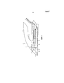
фиг.1 - схематичный вид в разрезе парового утюга настоящего изобретения;figure 1 is a schematic sectional view of a steam iron of the present invention;
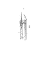
фиг.2 - увеличенный схематичный вид в разрезе участка парового утюга на фиг.1; иfigure 2 is an enlarged schematic view in section of a section of a steam iron in figure 1; and
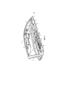
фиг.3 - вид в разрезе парового утюга настоящего изобретения.figure 3 is a view in section of a steam iron of the present invention.
Подробное описание вариантов осуществленияDetailed Description of Embodiments
На фиг.3 изображен паровой утюг 10 настоящего изобретения, и на фиг.1 и 2, соответственно, изображены упрощенные схематичные виды парового утюга 10 и увеличенный участок парового утюга 10 настоящего изобретения для более понятной иллюстрации его конфигурации и работы. Паровой утюг 10 содержит корпус 11, включающий в себя ручку 12 и подошву 13, соединенные с корпусом 11. Подошва 13 включает в себя нагревательный элемент 14. Нагревательный элемент 14 может в примере осуществления настоящего изобретения содержать электрический нагревательный элемент. Ссылки ниже на «верхний» и «нижний» или «верхний» и «нижний» участки парового утюга 10 относятся к паровому утюгу 10, находящемуся в рабочем положении, как показано на фиг.1 и 3, с подошвой 13, ориентированной обычно в горизонтальной плоскости.FIG. 3 shows a
Паровой утюг 10 также содержит входное соединение 16, сепаратор 18 для отделения воды от пара и испарительную камеру 19, соединенную по текучей среде между сепаратором 18 для отделения воды от пара и входным соединением 16. В примере осуществления парового утюга 10 настоящего изобретения, изображенного на фиг.1-3, входное соединение 16 соединено с сепаратором 18 для отделения воды от пара с помощью входного канала 17. Однако, настоящее изобретение не ограничивается этой конфигурацией, и входное соединение 16, например, может быть соединено непосредственно с сепаратором 18 для отделения воды от пара без отдельного соединительного канала. Пар подается во входное соединение 16 из парогенератора в отдельной подставке (не показано) через шланг 20 для подачи пара, который соединен с входным соединением 16. В примере осуществления настоящего изобретения сепаратор для отделения воды от пара может содержать циклонный сепаратор.The
Ручка 12 включает в себя кнопку 21, приводимую в действие пользователем, которая электрически соединена с парогенератором в отдельной подставке (не показано) для приведения в действие электроклапана для выпуска пара в утюг 10 при приведении в действие кнопки 21.The
Сепаратор 18 для отделения воды от пара содержит усеченно-конический кожух 22, сужающийся от верхнего участка к нижнему участку. Центральная паровая трубка 23 расположена в усеченно-коническом кожухе 22 и имеет открытый верхний конец рядом с верхней частью усеченно-конического кожуха 22 и нижний конец, который находится в сообщении по текучей среде с распределительной камерой 24 с отверстиями для выхода пара в подошве 13. Распределительная камера 24 с отверстиями для выхода пара включает в себя ряд отверстий 25 для выхода пара, через которые пар, проходящий в распределительную камеру 24 с отверстиями для выхода пара из паровой трубки 23 сепаратора для отделения воды от пара, может подаваться на одежду, подлежащую обработке.The
Испарительная камера 19 содержит канал, который соединяет более широкий нижний конец усеченно-конического кожуха 22 с входным соединением 16. Одна сторона испарительной камеры 19 содержит верхнюю поверхность подошвы 13, которая, следовательно, является нагреваемой поверхностью. Как можно видеть на фиг.3, испарительная камера 19 содержит изогнутый канал, образованный верхней поверхностью подошвы 13, выступающими вверх стенками 26 на верхней поверхности подошвы 13, и паровой крышкой 27, которая уплотняет по верхним частям выступающих вверх стенок 26. Следовательно, выступающие вверх стенки 26 также нагреваются нагревательным элементом 14.The
Участок парового утюга 10 в пунктирном прямоугольнике на фиг.1 изображен в увеличенном схематичном виде на фиг.2. Входное соединение 16 включает в себя первый входной канал 28 и второй входной канал 29 и выходной канал 30. Первый входной канал 28 соединено со шлангом 20 для подачи пара для подачи пара (показано стрелкой ʺSʺ на фиг.2), второй входной канал 29 соединен с концом испарительной камеры 19, удаленным от сепаратора 18 для отделения воды от пара, и выходной канал 30 соединен с входным каналом 17. Входное соединение содержит насадку с эффектом Вентури и, по существу, включает в себя узкую внутреннюю насадку 31, соединенную с первым входным каналом 28 и более широкую наружную трубку 32. Узкая внутренняя насадка 31 расположена в наружной трубке 32, и наружная трубка 32 включает в себя второй входной канал 29 и выходной канал 30.The plot of the
Во время использования парового утюга 10 пользователь приводит в действие кнопку 21, которая приводит в действие электроклапан (не показан) в парогенераторе в отдельной подставке (не показано) для принудительной подачи сжатого пара через шланг 20 для подачи пара в паровой утюг 10. Пар проходит во входное соединение 16 через первый входной канал 28 и проходит во входной канал 17 через конец узкой внутренней насадки 31. Узкая внутренняя насадка 31 заставляет пар выходить с высокой скоростью во входной канал 17. Пар, который сконденсировался в шланге 20 для подачи пара в жидкую воду, выходит с паром в виде капелек ʺdʺ воды (см. фиг.3) во входной канал 17.During use of the
Пар и вовлеченные капельки воды проходят вперед по входному каналу 17 и по касательной в сепаратор 18 для отделения воды от пара, где они вращаются в вихревом потоке в усеченно-коническом кожухе 22. Тяжелые капельки воды падают на дно сепаратора 18 для отделения воды от пара и в испарительную камеру 19, как показано стрелками ʺDʺ на фиг.1 и 2. Сухой пар проходит к верхней части сепаратора 18 для отделения воды от пара и в центральную паровую трубку 23, как показано стрелками ʺSʺ на фиг.1, из которой пар проходит в распределительную камеру 24 с отверстиями для выхода пара и выходит из отверстий 25 для выхода пара на одежду, подлежащую обработке.The steam and the involved water droplets pass forward through the
Капельки d воды, которые падают на дно сепаратора 18 для отделения воды от пара, проходят через испарительную камеру 19 к входному соединению 16. Тепло подошвы 13 и выступающих вверх стенок 26 в испарительной камере 19 нагревает капельки d воды и превращает в пар. Этот пар всасывается во входное соединение 16 за счет эффекта Вентури, обусловленного узкой внутренней насадкой 31 в наружной трубке 32. То есть, ускоренный пар, вышедший из узкой внутренней насадке 31, образует область ʺLʺ низкого давления (изображено с помощью окружностей на фиг.2) в наружной трубке 32 вверх по потоку от выходного конца входной трубки 31. Второй входной канал 29 расположен вверх по потоку от узкой внутренней насадки 31 относительно направления потока пара, выходящего из узкой внутренней насадки 31. Область L низкого давления всасывает пар из испарительной камеры 19 через второй входной канал 29 в наружную трубку 32, откуда он смешивается с паром, выходящим из узкой внутренней насадки 31, и вместе с ним затем выходит из выходного канала 30 во входной канал 17. Удаление пара из испарительной камеры 19, таким образом, также всасывает капельки d воды в испарительную камеру 19 из сепаратора 18 для отделения воды от пара.Water droplets d, which fall on the bottom of the
Когда из входного канала 17 пар проходит снова в сепаратор 18 для отделения воды от пара, где оставшиеся капельки воды отделяются от пара, как описано выше, они превращаются в пар в испарительной камере 19. Эта циркуляция капелек воды из сепаратора 18 для отделения воды от пара через испарительную камеру 19 и в виде пара обратно во входное соединение 16 продолжается, в то время как паровой утюг 10 используется, до тех пор, пока вся вода не выйдет из сепаратора 18 для отделения воды от пара в виде сухого пара.When steam passes from the
В случае вышеописанной конфигурации входного соединения 16 с эффектом Вентури конденсат из шланга 20 для подачи пара может удерживаться в течение более длительного периода, пока он повторно не превратится снова в пар. В качестве альтернативы, вода может удерживаться в испарительной камере 19 для медленного испарения, в то время как паровой утюг 10 находится в состоянии покоя (например, когда пользователь меняет или распрямляет одежду, подлежащую обработке). Следовательно, конструкция подошвы может иметь меньшую массу с нагревательным элементом 14 небольшой мощности, поскольку существует гораздо меньшая потребность в сохранении энергии, чем в известных конфигурациях парового утюга. Кроме того, не требуется система возврата воды из парового утюга 10 обратно в емкость для воды в подставке парового утюга (не показана), таким образом, шнур шланга для подачи пара может быть легким и гибким.In the case of the above configuration of the
Вместе с сухим паром, всасываемым через второй входной канал 29 из испарительной камеры 19 во входное соединение, некоторые капельки воды могут переноситься потоком пара во входное соединение 16. Однако, так как эти капельки проходят через входное соединение 16 и сталкиваются с быстро перемещающимся паром, выходящим из узкой внутренней насадки 31, они ускоряются в быстро перемещающемся потоке пара и, таким образом, распыляются. Следовательно, они могут превращаться в пар за счет струи горячего пара, выходящего из узкой внутренней насадки 31 или могут оставаться в сепараторе 18 для отделения воды от пара, где они будут циркулировать обратно через испарительную камеру 19, как описано выше, и превращаться обратно в пар.Together with the dry steam that is sucked in through the
Входной канал 17 вниз по потоку от входного соединения 16 преимущественно оказывает меньшее сопротивление потоку текучей среды, чем первый и второй входные каналы 28, 29 и выходной канал 30 входного соединения 16. Это способствует обеспечению образования зон L низкого давления, которые приводят к всасывающему эффекту для просасывания пара и всасывания неиспаренных капелек воды из испарительной камеры 19 непосредственно вверх по потоку от точки во входном соединении 16, из которой сжатый пар выходит из узкой внутренней насадки 31. Например, трубка, которая содержит входной канал 17, может иметь большее поперечное сечение, чем выходной канал 30 входного соединения 16. Кроме того, для предотвращения сопротивления потоку вниз по потоку от входного соединения 16 для поддержания эффекта Вентури площадь поперечного сечения входного канала в сепаратор 18 для отделения воды от пара также может иметь большее поперечное сечение, чем выходной канал 30 входного соединения 16. Кроме того, отверстие в центральной паровой трубке 23 и/или общая площадь поперечного сечения отверстий 25 для выхода пара преимущественно больше площади поперечного сечения выходного канала 30 входного соединения 16.The
На фиг.3 изображен пример конфигурации парового утюга 10 настоящего изобретения, в которой сепаратор 18 для отделения воды от пара может быть образован из двух частей с использованием центральной паровой трубки 23 и основания сепаратора 18 для отделения воды от пара, образованного как часть подошвы 13, и усеченно-конического кожуха 22, образованного в виде отдельного элемента. Усеченно-конический кожух 22 может быть отдельным от паровой крышки 27 или может быть выполнен как одно целое с паровой крышкой 27. Усеченно-конический кожух 22 и/или паровая крышка 27 могут быть выполнены из жаростойкого пластика в целях уменьшения веса или могут быть выполнены из металла.Figure 3 shows an example configuration of a
Отверстие в центральной паровой трубке 23 преимущественно имеет большую площадь поперечного сечения, чем входной канал сепаратора 18 для отделения воды от пара со стороны входного канала 17. Это способствует предотвращению сопротивления потоку в сепараторе 18 для отделения воды от пара.The hole in the
Подошва известного парового утюга с генератором сжатого пара обычно будет иметь массу около 800 г. Как описано выше, эта относительно большая масса необходима для сохранения внутренней энергии для быстрого повторного испарения конденсата. Однако, в случае парового утюга 10 в соответствии с настоящим изобретением может быть использована подошва 13 гораздо меньшей массы, и в одном примере осуществления масса подошвы может составлять около 400 г.The sole of a known steam iron with a compressed steam generator will typically have a mass of about 800 g. As described above, this relatively large mass is necessary to conserve internal energy for rapid re-evaporation of the condensate. However, in the case of the
Принимая во внимание корпус и другие элементы паровых утюгов с генератором сжатого пара, известные паровые утюги с генератором сжатого пара могут весить в пределах 1,0-1,6 кг и обычно около 1,2 кг. Однако, в случае конфигурации парового утюга настоящего изобретения общая масса парового утюга может быть меньше 800 г и может находиться в диапазоне 650-800 г, оптимальном весовом диапазоне для парового утюга с генератором сжатого пара для легкого использования как в вертикальном, так и в горизонтальном способах глажки.Taking into account the housing and other elements of steam irons with a compressed steam generator, known steam irons with a compressed steam generator can weigh between 1.0-1.6 kg and usually about 1.2 kg. However, in the case of the configuration of the steam iron of the present invention, the total weight of the steam iron may be less than 800 g and may be in the range of 650-800 g, the optimal weight range for a steam iron with a compressed steam generator for easy use in both vertical and horizontal methods ironing.
Для нагревательного элемента подошвы известного парового утюга с генератором сжатого пара обычно требуется выходная мощность 800 Вт для нагрева относительно большой массы подошвы в течение допустимого рабочего времени и повторного нагрева подошвы, так как тепло передается во время испарения сконденсированных капелек воды для предотвращения слишком большого падения температуры подошвы. Однако, в случае парового утюга 10 в соответствии с настоящим изобретением мощность нагревательного элемента 14 может быть ниже мощности нагревательного элемента в известных паровых утюгах с генератором сжатого пара, поскольку режим работы парового утюга 10 обеспечивает больше времени для превращения в пар сконденсированных капелек d воды, и имеется меньшая масса подошвы 13 для нагрева/повторного нагрева. В примере осуществления настоящего изобретения 7 г конденсата может испаряться в течение 10 сек. Использования. Для испарения 7 г воды может быть использован нагревательный элемент с мощностью 300 Вт, и дополнительные 200 Вт мощности могут быть представлены с учетом потерь тепла во время процесса глажки. Следовательно, подошва 13 примера осуществления настоящего изобретения может содержать нагревательный элемент 14 с мощностью около 500 Вт, и варианты осуществления настоящего изобретения могут иметь максимально допустимую мощность 500 Вт для нагревательных элементов 14 подошвы.An outboard heating element of a known steam iron with a compressed-steam generator usually requires an output power of 800 W to heat a relatively large mass of the sole for a reasonable working time and reheat the sole, since heat is transferred during the evaporation of condensed water droplets to prevent the sole temperature from dropping too much . However, in the case of the
В случае пониженной мощности, необходимой для подошвы 13, больше мощности от источника сетевого питания может быть использовано для бойлера/парогенератора для генерации большего количества пара. Некоторые страны имеют нормативные требования к максимальной мощности для бытовых изделий, которые в некоторых странах составляют 300 Вт. Потребление нагревательным элементом 14 подошвы 13 меньшей части от электроэнергии всей системы парового утюга с генератором сжатого пара, означает то, что большая часть этого конечного показателя максимальной мощности доступна для генерации пара в бойлере. Соответственно, эффективность системы парового утюга с генератором сжатого пара может быть увеличена по сравнению с известными паровыми утюгами с генератором сжатого пара, так как было доказано, что эффективность парового утюга при удалении складок зависит от количества пара, которое система глажки с запариванием может производить.In the case of reduced power required for the sole 13, more power from the mains supply can be used for the boiler / steam generator to generate more steam. Some countries have regulatory requirements for maximum power for household products, which in some countries are 300 watts. The consumption by the
В примерах осуществления парового утюга 10 настоящего изобретения, изображенного и описанного выше, второй входной канал 29, который проходит от испарительной камеры 19 во входное соединение, расположен под углом 90° к оси входного соединения 16, то есть оси узкой внутренней насадки 31 и наружной трубки 32. Однако, настоящее изобретение не ограничивается этой конкретной конфигурацией, и, преимущественно, угол между каналом, который содержит второй входной канал 29, и наружной трубкой может быть меньше 90°.In embodiments of the
Паровой утюг 10 настоящего изобретения выполнен таким образом, что канал, который содержит второй входной канал 29 входного соединения 16, проходит в испарительную камеру 19 и заканчивается на дистальном конце, который отделен от противоположной поверхности испарительной камеры 19 узким зазором ʺGʺ (как показано на фиг.2). Этот зазор G в примере осуществления настоящего изобретения, изображенном на фиг.1-3, является расстоянием между дистальным концом трубки второго входного канала 29 в испарительной камере 19 и верхней поверхностью подошвы в испарительной камере 19. Этот зазор G может составлять 1-4 мм и может преимущественно составлять около 2 мм. Этот небольшой зазор G способствует всасыванию неиспаренной воды на верхней поверхности подошвы 13 во входное соединение 16 под действием низкого давления L, обусловленного эффектом Вентури.The
Хотя в примерах осуществления парового утюга 10, описанного выше, испарительная камера нагревается нагревательным элементом 14 подошвы 13, настоящее изобретение не ограничивается этой конфигурацией, и в альтернативном варианте осуществления испарительная камера может содержать отдельный нагревательный элемент и/или может быть отдельной от подошвы 13.Although in the steam iron examples 10 described above, the evaporation chamber is heated by the
Вышеупомянутые варианты осуществления, описанные выше, являются только иллюстративными и не предназначены для ограничения технических методов настоящего изобретения. Хотя настоящее изобретение описано подробно со ссылкой на предпочтительные варианты осуществления, специалисты в данной области техники должны понимать, что технические методы настоящего изобретения могут быть модифицированы или в равной степени заменены без отхода от сущности и объема технических методов настоящего изобретения, которые будут также входить в область охранительного действия формулы изобретения настоящего изобретения. В формуле изобретения термин «содержащий» не исключает другие элементы или этапы, и неопределенный артикль ʺaʺ или ʺanʺ не исключает множество. Любые ссылочные позиции в формуле изобретения не должны истолковываться как ограничивающие объем формулы изобретения.The above embodiments described above are illustrative only and are not intended to limit the technical methods of the present invention. Although the present invention has been described in detail with reference to preferred embodiments, those skilled in the art should understand that the technical methods of the present invention can be modified or equally replaced without departing from the essence and scope of the technical methods of the present invention, which will also fall within the scope of the protective effect of the claims of the present invention. In the claims, the term “comprising” does not exclude other elements or steps, and the indefinite article ʺaʺ or ʺanʺ does not exclude a plurality. Any reference position in the claims should not be construed as limiting the scope of the claims.
Claims (14)
Applications Claiming Priority (3)
| Application Number | Priority Date | Filing Date | Title |
|---|---|---|---|
| EP14182184.3 | 2014-08-26 | ||
| EP14182184 | 2014-08-26 | ||
| PCT/EP2015/068403 WO2016030176A1 (en) | 2014-08-26 | 2015-08-11 | Steam iron |
Publications (3)
| Publication Number | Publication Date |
|---|---|
| RU2017109876A RU2017109876A (en) | 2018-09-27 |
| RU2017109876A3 RU2017109876A3 (en) | 2019-01-11 |
| RU2681604C2 true RU2681604C2 (en) | 2019-03-11 |
Family
ID=51392131
Family Applications (1)
| Application Number | Title | Priority Date | Filing Date |
|---|---|---|---|
| RU2017109876A RU2681604C2 (en) | 2014-08-26 | 2015-08-11 | Steam iron |
Country Status (7)
| Country | Link |
|---|---|
| US (1) | US10081903B2 (en) |
| EP (1) | EP3194647B1 (en) |
| CN (1) | CN106661817B (en) |
| MY (1) | MY183384A (en) |
| RU (1) | RU2681604C2 (en) |
| TR (1) | TR201818970T4 (en) |
| WO (1) | WO2016030176A1 (en) |
Families Citing this family (6)
| Publication number | Priority date | Publication date | Assignee | Title |
|---|---|---|---|---|
| CN108315960A (en) * | 2017-01-16 | 2018-07-24 | 青岛海尔滚筒洗衣机有限公司 | A kind of washing machine |
| FR3072099B1 (en) * | 2017-10-05 | 2019-09-20 | Seb S.A. | DEFROSTING HEAD COMPRISING AN INTERNAL CHAMBER WITH VAPOR EXPULSION CHANNELS |
| FR3072102B1 (en) * | 2017-10-05 | 2020-07-31 | Seb Sa | STRAINING HEAD INCLUDING AN INTERNAL CHAMBER PROVIDED WITH STEAM EXHAUST CHANNELS |
| WO2019227923A1 (en) * | 2018-05-31 | 2019-12-05 | 广东美的环境电器制造有限公司 | Heating body assembly, ironing head, and ironing device |
| CN113445289B (en) * | 2020-03-24 | 2024-07-16 | 青岛海尔洗衣机有限公司 | Ironing machine |
| KR102367079B1 (en) * | 2021-10-22 | 2022-02-25 | 주식회사 한울시스템 | Steam ironing system for vehicle seat cover |
Citations (3)
| Publication number | Priority date | Publication date | Assignee | Title |
|---|---|---|---|---|
| WO2008065619A1 (en) * | 2006-11-28 | 2008-06-05 | Koninklijke Philips Electronics N.V. | Steaming device |
| EP2418318A1 (en) * | 2010-08-12 | 2012-02-15 | Koninklijke Philips Electronics N.V. | Iron featuring liquid phase garment moisturization |
| EP2808439A1 (en) * | 2013-05-30 | 2014-12-03 | Seb S.A. | Steam ironing appliance |
Family Cites Families (14)
| Publication number | Priority date | Publication date | Assignee | Title |
|---|---|---|---|---|
| US1593897A (en) * | 1924-10-24 | 1926-07-27 | Cannon Engineering Co | Pressing appliance |
| US1674092A (en) * | 1926-03-12 | 1928-06-19 | Cannon Engineering Co | Sadiron |
| US2460546A (en) * | 1942-10-01 | 1949-02-01 | C H Wheeler Mfg Co | Method and apparatus for treating materials |
| US2803073A (en) * | 1953-11-18 | 1957-08-20 | Gen Mills Inc | Steam iron |
| US2815593A (en) * | 1954-09-13 | 1957-12-10 | Reimers Electric Appliance Co | Steam pressing iron and steam-supply mechanism therefor |
| FR2740787B1 (en) * | 1995-11-03 | 1999-06-11 | Moulinex Sa | STEAM IRON |
| FR2771110B1 (en) | 1997-11-19 | 1999-12-24 | Seb Sa | IRONING APPARATUS AND METHOD WITH GENERATION OF STEAM |
| JP3646076B2 (en) * | 2001-06-19 | 2005-05-11 | 直本工業株式会社 | All steam iron |
| US6874771B2 (en) * | 2002-08-09 | 2005-04-05 | Kaz, Inc. | Humidifier with a heating disc |
| DE102004032361B4 (en) * | 2004-07-03 | 2009-12-10 | Braun Gmbh | Method of providing steam and corresponding steam iron |
| EP2251482A1 (en) * | 2009-05-14 | 2010-11-17 | Koninklijke Philips Electronics N.V. | Steam discharge unit for use in a soleplate of a steam iron |
| CN202116907U (en) * | 2011-06-02 | 2012-01-18 | 浙江华光电器集团有限公司 | Modified structure of steam brush |
| JP5187707B2 (en) * | 2011-08-12 | 2013-04-24 | 株式会社ビクター特販 | Heat recovery device and heat recovery system |
| TR201819499T4 (en) * | 2014-08-26 | 2019-01-21 | Koninklijke Philips Nv | A steam iron head. |
-
2015
- 2015-08-11 EP EP15748042.7A patent/EP3194647B1/en active Active
- 2015-08-11 MY MYPI2017700597A patent/MY183384A/en unknown
- 2015-08-11 CN CN201580045854.4A patent/CN106661817B/en not_active Expired - Fee Related
- 2015-08-11 RU RU2017109876A patent/RU2681604C2/en not_active IP Right Cessation
- 2015-08-11 US US15/504,031 patent/US10081903B2/en not_active Expired - Fee Related
- 2015-08-11 WO PCT/EP2015/068403 patent/WO2016030176A1/en active Application Filing
- 2015-08-11 TR TR2018/18970T patent/TR201818970T4/en unknown
Patent Citations (3)
| Publication number | Priority date | Publication date | Assignee | Title |
|---|---|---|---|---|
| WO2008065619A1 (en) * | 2006-11-28 | 2008-06-05 | Koninklijke Philips Electronics N.V. | Steaming device |
| EP2418318A1 (en) * | 2010-08-12 | 2012-02-15 | Koninklijke Philips Electronics N.V. | Iron featuring liquid phase garment moisturization |
| EP2808439A1 (en) * | 2013-05-30 | 2014-12-03 | Seb S.A. | Steam ironing appliance |
Also Published As
| Publication number | Publication date |
|---|---|
| RU2017109876A (en) | 2018-09-27 |
| EP3194647A1 (en) | 2017-07-26 |
| EP3194647B1 (en) | 2018-10-10 |
| MY183384A (en) | 2021-02-18 |
| CN106661817B (en) | 2019-09-24 |
| US10081903B2 (en) | 2018-09-25 |
| CN106661817A (en) | 2017-05-10 |
| TR201818970T4 (en) | 2019-01-21 |
| WO2016030176A1 (en) | 2016-03-03 |
| RU2017109876A3 (en) | 2019-01-11 |
| US20170268160A1 (en) | 2017-09-21 |
Similar Documents
| Publication | Publication Date | Title |
|---|---|---|
| RU2681604C2 (en) | Steam iron | |
| RU2650059C1 (en) | Steam head of iron | |
| RU2689043C2 (en) | Working part of steam iron | |
| CN101563496B (en) | A device for supplying superheated water | |
| US10287726B2 (en) | Garment steamer | |
| US20140007450A1 (en) | Dryer | |
| RU2689078C2 (en) | Steam device | |
| RU2689064C2 (en) | Working part of steam iron | |
| JP2005009850A (en) | Device for heating material, particularly food | |
| RU2643972C2 (en) | Steam ironing device | |
| RU2677596C2 (en) | Steaming device component | |
| JP5384150B2 (en) | Heat exchanger | |
| WO2008065619A1 (en) | Steaming device | |
| JP4456008B2 (en) | Cooker | |
| CN202881726U (en) | Dual-heating electric iron base plate | |
| WO2020078305A1 (en) | Ironing device | |
| CN206817436U (en) | Steam raising plant | |
| SU77758A1 (en) | Water overheating deaerator | |
| TWM563231U (en) | Backflow stopping structure of steam cooking machine | |
| JP4885891B2 (en) | Vacuum steam heater | |
| KR100737778B1 (en) | Steam boiler and steam and vacuum cleaner | |
| KR20160083244A (en) | Heat exchanger of cooker | |
| JP2009097560A (en) | Vapor eliminator of steam trap |
Legal Events
| Date | Code | Title | Description |
|---|---|---|---|
| MM4A | The patent is invalid due to non-payment of fees |
Effective date: 20200812 |