RU2680442C2 - Device for connecting structural element with holding element spaced apart - Google Patents
Device for connecting structural element with holding element spaced apart Download PDFInfo
- Publication number
- RU2680442C2 RU2680442C2 RU2016139262A RU2016139262A RU2680442C2 RU 2680442 C2 RU2680442 C2 RU 2680442C2 RU 2016139262 A RU2016139262 A RU 2016139262A RU 2016139262 A RU2016139262 A RU 2016139262A RU 2680442 C2 RU2680442 C2 RU 2680442C2
- Authority
- RU
- Russia
- Prior art keywords
- distance
- correcting
- structural
- insert
- structural element
- Prior art date
Links
- 238000004026 adhesive bonding Methods 0.000 claims abstract description 10
- 239000003733 fiber-reinforced composite Substances 0.000 claims abstract description 7
- 239000002861 polymer material Substances 0.000 claims abstract description 6
- 230000008878 coupling Effects 0.000 claims description 44
- 238000010168 coupling process Methods 0.000 claims description 44
- 238000005859 coupling reaction Methods 0.000 claims description 44
- 239000000853 adhesive Substances 0.000 claims description 12
- 230000001070 adhesive effect Effects 0.000 claims description 12
- 230000005489 elastic deformation Effects 0.000 claims description 5
- 238000009434 installation Methods 0.000 claims description 4
- 238000003780 insertion Methods 0.000 abstract description 15
- 230000037431 insertion Effects 0.000 abstract description 15
- 230000000694 effects Effects 0.000 abstract 1
- 239000000126 substance Substances 0.000 abstract 1
- 239000002131 composite material Substances 0.000 description 12
- 239000000463 material Substances 0.000 description 5
- 239000011120 plywood Substances 0.000 description 2
- 230000002269 spontaneous effect Effects 0.000 description 2
- 238000005253 cladding Methods 0.000 description 1
- 230000001419 dependent effect Effects 0.000 description 1
- 238000005553 drilling Methods 0.000 description 1
- 239000013013 elastic material Substances 0.000 description 1
- 239000003292 glue Substances 0.000 description 1
- 238000005304 joining Methods 0.000 description 1
- 238000004519 manufacturing process Methods 0.000 description 1
- 238000003801 milling Methods 0.000 description 1
- 238000003825 pressing Methods 0.000 description 1
- 238000005096 rolling process Methods 0.000 description 1
- 238000000926 separation method Methods 0.000 description 1
Images
Classifications
-
- F—MECHANICAL ENGINEERING; LIGHTING; HEATING; WEAPONS; BLASTING
- F16—ENGINEERING ELEMENTS AND UNITS; GENERAL MEASURES FOR PRODUCING AND MAINTAINING EFFECTIVE FUNCTIONING OF MACHINES OR INSTALLATIONS; THERMAL INSULATION IN GENERAL
- F16B—DEVICES FOR FASTENING OR SECURING CONSTRUCTIONAL ELEMENTS OR MACHINE PARTS TOGETHER, e.g. NAILS, BOLTS, CIRCLIPS, CLAMPS, CLIPS OR WEDGES; JOINTS OR JOINTING
- F16B5/00—Joining sheets or plates, e.g. panels, to one another or to strips or bars parallel to them
- F16B5/01—Joining sheets or plates, e.g. panels, to one another or to strips or bars parallel to them by means of fastening elements specially adapted for honeycomb panels
-
- B—PERFORMING OPERATIONS; TRANSPORTING
- B64—AIRCRAFT; AVIATION; COSMONAUTICS
- B64C—AEROPLANES; HELICOPTERS
- B64C1/00—Fuselages; Constructional features common to fuselages, wings, stabilising surfaces or the like
- B64C1/06—Frames; Stringers; Longerons ; Fuselage sections
- B64C1/12—Construction or attachment of skin panels
-
- B—PERFORMING OPERATIONS; TRANSPORTING
- B64—AIRCRAFT; AVIATION; COSMONAUTICS
- B64D—EQUIPMENT FOR FITTING IN OR TO AIRCRAFT; FLIGHT SUITS; PARACHUTES; ARRANGEMENT OR MOUNTING OF POWER PLANTS OR PROPULSION TRANSMISSIONS IN AIRCRAFT
- B64D11/00—Passenger or crew accommodation; Flight-deck installations not otherwise provided for
- B64D11/02—Toilet fittings
-
- F—MECHANICAL ENGINEERING; LIGHTING; HEATING; WEAPONS; BLASTING
- F16—ENGINEERING ELEMENTS AND UNITS; GENERAL MEASURES FOR PRODUCING AND MAINTAINING EFFECTIVE FUNCTIONING OF MACHINES OR INSTALLATIONS; THERMAL INSULATION IN GENERAL
- F16B—DEVICES FOR FASTENING OR SECURING CONSTRUCTIONAL ELEMENTS OR MACHINE PARTS TOGETHER, e.g. NAILS, BOLTS, CIRCLIPS, CLAMPS, CLIPS OR WEDGES; JOINTS OR JOINTING
- F16B37/00—Nuts or like thread-engaging members
- F16B37/04—Devices for fastening nuts to surfaces, e.g. sheets, plates
- F16B37/041—Releasable devices
- F16B37/042—Releasable devices locking by rotation
-
- F—MECHANICAL ENGINEERING; LIGHTING; HEATING; WEAPONS; BLASTING
- F16—ENGINEERING ELEMENTS AND UNITS; GENERAL MEASURES FOR PRODUCING AND MAINTAINING EFFECTIVE FUNCTIONING OF MACHINES OR INSTALLATIONS; THERMAL INSULATION IN GENERAL
- F16B—DEVICES FOR FASTENING OR SECURING CONSTRUCTIONAL ELEMENTS OR MACHINE PARTS TOGETHER, e.g. NAILS, BOLTS, CIRCLIPS, CLAMPS, CLIPS OR WEDGES; JOINTS OR JOINTING
- F16B39/00—Locking of screws, bolts or nuts
- F16B39/22—Locking of screws, bolts or nuts in which the locking takes place during screwing down or tightening
- F16B39/28—Locking of screws, bolts or nuts in which the locking takes place during screwing down or tightening by special members on, or shape of, the nut or bolt
- F16B39/32—Locking by means of a pawl or pawl-like tongue
-
- F—MECHANICAL ENGINEERING; LIGHTING; HEATING; WEAPONS; BLASTING
- F16—ENGINEERING ELEMENTS AND UNITS; GENERAL MEASURES FOR PRODUCING AND MAINTAINING EFFECTIVE FUNCTIONING OF MACHINES OR INSTALLATIONS; THERMAL INSULATION IN GENERAL
- F16B—DEVICES FOR FASTENING OR SECURING CONSTRUCTIONAL ELEMENTS OR MACHINE PARTS TOGETHER, e.g. NAILS, BOLTS, CIRCLIPS, CLAMPS, CLIPS OR WEDGES; JOINTS OR JOINTING
- F16B5/00—Joining sheets or plates, e.g. panels, to one another or to strips or bars parallel to them
- F16B5/02—Joining sheets or plates, e.g. panels, to one another or to strips or bars parallel to them by means of fastening members using screw-thread
- F16B5/0216—Joining sheets or plates, e.g. panels, to one another or to strips or bars parallel to them by means of fastening members using screw-thread the position of the plates to be connected being adjustable
- F16B5/0233—Joining sheets or plates, e.g. panels, to one another or to strips or bars parallel to them by means of fastening members using screw-thread the position of the plates to be connected being adjustable allowing for adjustment perpendicular to the plane of the plates
-
- F—MECHANICAL ENGINEERING; LIGHTING; HEATING; WEAPONS; BLASTING
- F16—ENGINEERING ELEMENTS AND UNITS; GENERAL MEASURES FOR PRODUCING AND MAINTAINING EFFECTIVE FUNCTIONING OF MACHINES OR INSTALLATIONS; THERMAL INSULATION IN GENERAL
- F16B—DEVICES FOR FASTENING OR SECURING CONSTRUCTIONAL ELEMENTS OR MACHINE PARTS TOGETHER, e.g. NAILS, BOLTS, CIRCLIPS, CLAMPS, CLIPS OR WEDGES; JOINTS OR JOINTING
- F16B5/00—Joining sheets or plates, e.g. panels, to one another or to strips or bars parallel to them
- F16B5/02—Joining sheets or plates, e.g. panels, to one another or to strips or bars parallel to them by means of fastening members using screw-thread
- F16B5/025—Joining sheets or plates, e.g. panels, to one another or to strips or bars parallel to them by means of fastening members using screw-thread specially designed to compensate for misalignement or to eliminate unwanted play
-
- F—MECHANICAL ENGINEERING; LIGHTING; HEATING; WEAPONS; BLASTING
- F16—ENGINEERING ELEMENTS AND UNITS; GENERAL MEASURES FOR PRODUCING AND MAINTAINING EFFECTIVE FUNCTIONING OF MACHINES OR INSTALLATIONS; THERMAL INSULATION IN GENERAL
- F16B—DEVICES FOR FASTENING OR SECURING CONSTRUCTIONAL ELEMENTS OR MACHINE PARTS TOGETHER, e.g. NAILS, BOLTS, CIRCLIPS, CLAMPS, CLIPS OR WEDGES; JOINTS OR JOINTING
- F16B5/00—Joining sheets or plates, e.g. panels, to one another or to strips or bars parallel to them
- F16B5/02—Joining sheets or plates, e.g. panels, to one another or to strips or bars parallel to them by means of fastening members using screw-thread
- F16B5/0283—Joining sheets or plates, e.g. panels, to one another or to strips or bars parallel to them by means of fastening members using screw-thread with an externally threaded sleeve around the neck or the head of the screw-threaded element for adjustably fastening a plate or frame or the like to a fixed element
Landscapes
- Engineering & Computer Science (AREA)
- General Engineering & Computer Science (AREA)
- Mechanical Engineering (AREA)
- Aviation & Aerospace Engineering (AREA)
- Connection Of Plates (AREA)
Abstract
Description
Изобретение относится к устройству для соединения структурного элемента, в частности, из волокнисто - усиленного композитного полимерного материала, с фиксирующим элементом, с интервалом друг к другу посредством стяжного болта, с корректирующим дистанцию элементом, имеющим продольное отверстие для прохождения стяжного болта, и с расположенным в продольном отверстии с возможностью соединения посредством фрикционного замыкания со стяжным болтом захватывающим элементом, поэтому корректирующий дистанцию элемент при завертывании стяжного болта может переводиться в перекрывающее с интервалом между структурным элементом и фиксирующим элементом положение упора.The invention relates to a device for connecting a structural element, in particular, of a fiber-reinforced composite polymer material, with a fixing element, spaced to each other by a coupling bolt, with a distance-correcting element having a longitudinal opening for passage of the coupling bolt, and with a longitudinal hole with the possibility of connection by means of friction closure with a coupling bolt by a gripping element, therefore, the distance-correcting element when wrapping the tie th bolt can be converted into an overlapped with an interval between the structural member and the fixing member abutment.
Кроме того, изобретение относится к структурному элементу, в частности, из волокнисто - усиленного композитного полимерного материала.In addition, the invention relates to a structural element, in particular from a fiber reinforced composite polymer material.
Из публикации DE 10 151 383 AI известна компоновка для коррекции допустимого отклонения между двумя конструктивными элементами. Эта компоновка имеет болт, проходящий насквозь через оба конструктивных элемента. Головка винта опирается на первый конструктивный элемент. Болт завинчивают в гайку в другом конструктивном элементе. Кроме того, предусмотрена компенсационная втулка, имеющая сквозное отверстие и согласованную с внутренней резьбой гайки наружную резьбу. При этом компенсационная втулка имеет зажимной участок, с помощью которого она может соединяться с фрикционным замыканием с болтом, тогда как она имеет возможность поворота относительно болта при преодолении фрикционного замыкания. При установке болта в компенсационную втулку и его поворачивании, компенсационная втулка может поворачиваться вместе с ним вследствие фрикционного замыкания. Благодаря этому компенсационная втулка вывинчивается навстречу направлению движения установки из гайки для коррекции допустимого отклонения. После установки компенсационной втулки в первый конструктивный элемент, ее завинчивают с помощью внутренней резьбы для затягивания обоих конструктивных элементов.From the
В публикации DE 10 2008 055 526 AI и DE 10 2007 037 242 AI описаны другие устройства этого вида.
В WO 2 013 150 016 AI заявлен крепежный элемент для соединения двух конструктивных элементов с помощью автоматической коррекции допустимого отклонения между конструктивными элементами. Крепежный элемент имеет основной элемент, с возможностью фиксации в отверстии одного конструктивного элемента и регулировочный элемент, с возможностью завинчивания наружной резьбы во внутреннюю резьбу основного элемента. Рядом с внутренней резьбой основной элемент имеет второй (внутренний) участок резьбы для завинчивания крепежного болта, имеющего направление хода, противоположное направлению хода резьбы. Регулировочный элемент имеет на внутренней стороне захватываемые элементы, обеспечивающие фрикционно замкнутое соединение между болтом и регулировочным элементом при завинчивании болта. При завинчивании болта в участок резьбы регулировочный элемент проворачивается посредством захватывающих элементов, причем в зависимости от направления вращения болта регулировочный элемент двигается в осевом направлении, либо по направлению от основного элемента, либо к основному элементу, вследствие чего можно достигать коррекции допустимого отклонения. Согласно альтернативному выполнению, основной элемент можно вклеивать в отверстие конструктивного элемента.WO 2 013 150 016 AI discloses a fastener for joining two structural members by automatically correcting the tolerance between structural members. The fastening element has a main element, with the possibility of fixing in the hole of one structural element and an adjusting element, with the possibility of screwing the external thread into the internal thread of the main element. Next to the internal thread, the main element has a second (internal) thread section for screwing a mounting bolt having a travel direction opposite to the thread travel direction. The adjustment element has gripping elements on the inside that provide a frictionally closed connection between the bolt and the adjustment element when tightening the bolt. When the bolt is screwed into the thread section, the adjusting element is rotated by means of gripping elements, and depending on the direction of rotation of the bolt, the adjusting element moves in the axial direction, either in the direction from the main element or to the main element, as a result of which a correction of the permissible deviation can be achieved. According to an alternative embodiment, the main element can be glued into the hole of the structural element.
В этом уровне техники головка болта опирается на конструктивный элемент. В нежелательном случае конструктивный элемент может повреждаться моментом затяжки болта. Это является недостатком, в частности тогда, когда конструктивный элемент изготовлен из волокнистого композитного материала. Кроме того, известное устройство не подходит вследствие проблем раскалывания для фиксации композитных конструктивных элементов. Наконец, выступающая головка болта портит внешний вид видимой поверхности конструктивного элемента.In this prior art, a bolt head is supported by a structural member. In an undesirable case, the structural element may be damaged by the tightening torque of the bolt. This is a disadvantage, in particular when the structural element is made of a fibrous composite material. In addition, the known device is not suitable due to splitting problems for fixing composite structural elements. Finally, the protruding head of the bolt spoils the appearance of the visible surface of the structural element.
Поэтому известные выполнения не подходят для многих вариантов применения, в частности, в авиастроении. Неудачным для фиксации конструктивных элементов структуры из композитных материалов в отношении прочности и безопасности нагрузки является то, что стяжной болт фиксирован с помощью головки болта на верхней стороне композитного материала. Кроме того, компоновка коррекции допустимого отклонения от уровня техники, сравните, например, с публикацией DE 101 51 383 AI, соединена с гайкой фиксирующего элемента. Однако такое выполнение было бы неподходящим или неблагоприятным для фиксации композитных конструктивных элементов вследствие проблем раскалывания.Therefore, the known implementation is not suitable for many applications, in particular, in the aircraft industry. Unsuccessful for fixing structural elements of the composite structure in terms of strength and safety of the load is that the coupling bolt is fixed with a bolt head on the upper side of the composite material. In addition, the layout of the correction of the permissible deviation from the prior art, compare, for example, with the publication DE 101 51 383 AI, connected to the nut of the locking element. However, such an implementation would be inappropriate or unfavorable for fixing composite structural elements due to splitting problems.
Следовательно, задача предложенного изобретения состоит в создании устройства прежде указанного вида, с помощью которого облегчаются или предотвращаются известные из уровня техники проблемы, в частности, устройства для коррекции допустимого отклонения для структурных элементов из композитных материалов.Therefore, the objective of the proposed invention is to create a device of the previously indicated type, with the help of which the problems known from the prior art are alleviated or prevented, in particular, devices for correcting the tolerance for structural elements made of composite materials.
Для решения этой задачи предусмотрено устройство с признаками независимого пункта 1 формулы изобретения и структурный элемент с признаками независимого пункта 13 формулы изобретения. Предпочтительные выполнения приведены в зависимых пунктах формулы изобретения.To solve this problem, a device is provided with features of
Согласно изобретению, корректирующий дистанцию элемент соединен посредством резьбового соединения с вставной деталью, имеющей установленный внутри структурного элемента крепежный участок для склеивания со структурным элементом.According to the invention, the distance-correcting element is connected by means of a threaded connection to an insert part having a fastening section mounted inside the structural element for gluing to the structural element.
Поэтому в смонтированном положении крепежный участок вставной детали установлен в выемке структурного элемента и неподвижно зафиксирован посредством клеевого соединения в примыкающем материале структурного элемента. Поэтому вставная деталь предпочтительно не выдается над противоположной фиксирующему элементу внешней поверхностью структурного элемента. Так что крепежный участок интегрирован предпочтительно, по существу, полностью в структурный элемент, предпочтительно имеющий панель из композитного материала. Кроме того, на структурном элементе с панелью из композитного материала может быть предусмотрена лицевая поверхность, в частности, из фанеры. Вставная деталь имеет на крепежном участке поверхность сцепления для склеивания с соответствующей, ограничивающей вырез структурного элемента клейкой поверхностью структурного элемента. Согласно изобретению, выполнение имеет, в частности, преимущество в том, что оно предотвращает точечный ввод нагрузки в структурный элемент, вызываемый в уровне техники опорой стяжного болта на внешнюю сторону конструктивного элемента. Кроме того, создается особенно стабильное выполнение, удовлетворяющее высоким стандартам безопасности. Более того, предпочтительно то, что компоновка корректирующего дистанцию элемента совсем не повреждает видимую поверхность структурного элемента, так как отсутствует выступающая согласно уровню техники головка винта. При соединении корректирующего дистанцию элемента со вставной деталью, - в отличие от соединения с гайкой фиксирующего элемента из уровня техники, - можно достигать, кроме того, особенно компактного выполнения, предпочтительного, в частности, для структурных элементов из волокнисто - усиленных композитных полимерных материалов (композитных конструктивных элементов). В этом выполнении фиксирующий элемент может быть оснащен сравнительно небольшой гайкой. Поэтому согласно изобретению устройство можно использовать с особенными преимуществами для монтажа структурных элементов из волокнисто - усиленного полимерного материала, имеющих, в частности, толщину стенки или толщину от 5 до 15 мм.Therefore, in the mounted position, the fixing portion of the insert is mounted in the recess of the structural element and is fixedly fixed by means of adhesive bonding in the adjacent material of the structural element. Therefore, the insertion member preferably does not protrude over the outer surface of the structural element opposite the fixing element. Thus, the fastening portion is preferably integrated substantially substantially completely into the structural element, preferably having a panel of composite material. In addition, a front surface, in particular plywood, can be provided on a structural element with a panel of composite material. The plug-in part has a bonding surface on the fastening portion for bonding with a corresponding, limiting cutout of the structural element, the adhesive surface of the structural element. According to the invention, the implementation has, in particular, an advantage in that it prevents the point loading of the load into the structural element caused in the prior art by the support of the coupling bolt on the outside of the structural element. In addition, a particularly stable execution is created that meets high safety standards. Moreover, it is preferable that the arrangement of the distance-correcting element does not damage the visible surface of the structural element at all, since there is no screw head protruding according to the prior art. By connecting the distance-correcting element with the insertion part, in contrast to the connection with the nut of the fixing element of the prior art, it is possible to achieve, in addition, a particularly compact design, preferred, in particular, for structural elements of fiber-reinforced composite polymeric materials (composite structural elements). In this embodiment, the locking element may be equipped with a relatively small nut. Therefore, according to the invention, the device can be used with particular advantages for mounting structural elements of fiber-reinforced polymeric material having, in particular, a wall thickness or a thickness of 5 to 15 mm.
Для перекрытия интервала между структурным элементом и фиксирующим элементом предпочтительно, если корректирующий дистанцию элемент можно переводить при завертывании стяжного болта из дистанционного положения - в направлении фиксирующего элемента в положение упора в фиксирующий элемент. Поэтому в таком варианте выполнения корректирующий дистанцию элемент при завертывании стяжного болта вывинчивается из вставной детали. Следовательно, движение поворота стяжного болта преобразуется в удлинение устройства, причем образующий упорную поверхность открытый конец корректирующего дистанцию элемента перемещается в направлении фиксирующего элемента. При достижении положения упора преодолевается фрикционное замыкание между стяжным болтом и захватывающим элементом, поэтому стяжной болт может поворачиваться относительно захватывающего элемента. Затем стяжной болт фиксируется в резьбе фиксирующего элемента.To overlap the interval between the structural element and the locking element, it is preferable if the distance-correcting element can be moved when the coupling bolt is wound from a remote position - in the direction of the fixing element to the stop position in the fixing element. Therefore, in such an embodiment, the distance-correcting element is unscrewed from the insertion part when wrapping the coupling bolt. Therefore, the rotation movement of the coupling bolt is converted to an extension of the device, the open end of the distance-correcting element forming the abutment surface moving in the direction of the locking element. Upon reaching the stop position, the frictional closure between the coupling bolt and the gripping element is overcome, so the coupling bolt can rotate relative to the gripping element. Then the coupling bolt is fixed in the thread of the locking element.
Для достижения прочного клеевого соединения между вставной деталью и структурным элементом предпочтительно, если вставная деталь имеет в крепежном участке, по меньшей мере, с возможностью установки между внешними поверхностями структурного элемента крепежный фланец для склеивания вставной детали со структурным элементом, причем, по меньшей мере, один крепежный фланец предпочтительно продолжается, по существу, вертикально к продольной оси продольного отверстия. При изготовлении крепежный фланец фиксируют посредством клеевого соединения на структурном элементе, вследствие чего достигают внутренней прочности. С одной стороны, компоновка крепежного фланца облегчает нанесение клеящего вещества. С другой стороны, крепежный фланец вызывает особенно надежную защиту от воздействующих при эксплуатации на устройство усилий скручивания. Предпочтительно крепежный фланец расположен, по существу, заподлицо с поверхностью панели композитного структурного элемента. In order to achieve a strong adhesive bond between the insertion part and the structural element, it is preferable if the insertion part has at least a possibility of installing between the outer surfaces of the structural element a fastening flange for gluing the insertion part with the structural element, at least one the mounting flange preferably extends substantially vertically to the longitudinal axis of the longitudinal hole. In the manufacture of the fastening flange is fixed by adhesive bonding on the structural element, thereby achieving internal strength. On the one hand, the mounting flange layout facilitates the application of adhesive. On the other hand, the mounting flange provides particularly reliable protection against torsional forces acting during operation of the device. Preferably, the mounting flange is substantially flush with the surface of the panel of the composite structural element.
Особенно предпочтителен вариант выполнения, в котором вставная деталь имеет расположенные в крепежном участке, в частности, параллельно и с интервалом друг к другу два крепежных фланца. С помощью них можно достигать особенно прочной компоновки вставной детали внутри выреза структурного элемента. Крепежные фланцы расположены в нем предпочтительно, по существу, полностью между внешними поверхностями структурного элемента, причем, по меньшей мере, один из крепежных фланцев закрывается предпочтительно, по существу, заподлицо поверхностью панели композитного материала структурного элемента. Между крепежными фланцами выполнена полость для приема клеящего вещества, с помощью которого вставную деталь фиксируют в структурном элементе. Для фиксации структурного элемента сначала в нем выполняют сверление с наружным диаметром крепежных фланцев. После установки вставной детали кольцеобразную полость между крепежными фланцами можно заполнять клеящим веществом. Клеящее вещество между крепежными фланцами соединяется с материалом, в частности, с композитным материалом структурного элемента.Particularly preferred is the embodiment in which the plug-in part has two mounting flanges located in the fastening section, in particular in parallel and at intervals to each other. With them, it is possible to achieve a particularly strong layout of the insert part inside the cutout of the structural element. The mounting flanges are preferably arranged substantially completely between the outer surfaces of the structural element, wherein at least one of the mounting flanges is preferably closed substantially flush with the surface of the panel of the composite material of the structural element. Between the mounting flanges there is a cavity for receiving adhesive, with which the insert is fixed in the structural element. To fix the structural element, drilling is first performed in it with the outer diameter of the mounting flanges. After installing the insert, the annular cavity between the mounting flanges can be filled with adhesive. The adhesive between the mounting flanges is connected with the material, in particular, with the composite material of the structural element.
Для склеивания вставной детали со структурным элементом предпочтительно, если, по меньшей мере один из крепежных фланцев имеет, по меньшей мере, одно отверстие, в частности, по меньшей мере, одну просечку во внешнем крае крепежного фланца для внесения клеящего вещества между крепежными фланцами. Предпочтительно один из крепежных фланцев имеет две расположенные напротив просечки для заполнения клеящим веществом. В зависимости от выполнения оба крепежных фланца могут иметь соответственно, по меньшей мере, одно отверстие для внесения клеящего вещества.For gluing an insert with a structural element, it is preferable if at least one of the mounting flanges has at least one opening, in particular at least one notch in the outer edge of the mounting flange for introducing adhesive between the mounting flanges. Preferably, one of the mounting flanges has two opposed perforations for filling with adhesive. Depending on the implementation, both mounting flanges may have at least one opening for applying adhesive, respectively.
Для максимальной возможности регулировки устройства, предпочтительно, если предусмотрены упоры для ограничения движения корректирующего дистанцию элемента относительно вставной детали в осевом направлении. В соответствии с этим устройство можно регулировать при прокручивании стяжного болта между более коротким положением, в котором корректирующий дистанцию элемент немного выступает из вставной детали, и более длинным положением, в котором корректирующий дистанцию элемент дальше выступает из вставной детали, причем упоры блокируют регулировку корректирующего дистанцию элемента после достижения более короткого или более длинного положения.For maximum adjustment of the device, it is preferable if stops are provided to limit the movement of the distance-correcting element relative to the insert part in the axial direction. Accordingly, the device can be adjusted by scrolling the clamping bolt between a shorter position in which the distance-correcting element protrudes slightly from the plug-in part and a longer position in which the distance-correcting element protrudes further from the plug-in part, and the stops block the adjustment of the distance-correcting element after reaching a shorter or longer position.
По технологическим причинам предпочтительно, если корректирующий дистанцию элемент имеет приемное отверстие для установки с возможностью отделения упорного элемента, с помощью которого можно блокировать в смонтированном положении вывинчивание корректирующего дистанцию элемента из вставной детали. Компоновка упорного элемента с возможностью отделения в приемном отверстии позволяет особенно просто монтировать или демонтировать устройство.For technological reasons, it is preferable if the distance-correcting element has a receiving hole for installation with the possibility of separating the thrust element, with which it is possible to block in the mounted position unscrewing the distance-correcting element from the insertion part. The arrangement of the thrust element with the possibility of separation in the receiving hole makes it particularly easy to mount or dismantle the device.
В этом варианте выполнения предпочтительно в качестве упорного элемента предусмотрен, в частности, U-образный бюгельный элемент, выступающий в смонтированном положении в продольное отверстие корректирующего дистанцию элемента. Концы бюгельного элемента можно задвигать в соответствующие приемные отверстия корректирующего дистанцию элемента. В смонтированном положении бюгельный элемент блокирует регулировку корректирующего дистанцию элемента после достижения имеющего максимальную длину второго положения устройства. Относительно особенно экономически целесообразного и конструктивно простого варианта выполнения в качестве бюгельного элемента может быть предусмотрена проволока, в частности, с круглым поперечным сечением, причем вырезы корректирующего дистанцию элемента выполняют в соответствии с ними. In this embodiment, it is preferable, in particular, to provide a stop element with a U-shaped clasp element which protrudes in a mounted position into a longitudinal opening of the distance-correcting element. The ends of the clasp element can be pushed into the corresponding receiving holes of the distance-correcting element. In the mounted position, the clasp element blocks the adjustment of the distance-correcting element after reaching the second position of the device having the maximum length. With respect to a particularly economically feasible and structurally simple embodiment, a clasp element can be provided with a wire, in particular with a circular cross-section, and cutouts of the distance-correcting element are made in accordance with them.
Предпочтителен бюгельный элемент с возможностью упругой деформации, так что бюгельный элемент в смонтированном положении, благодаря эластичной деформации вставленных через приемные отверстия концов бюгельного элемента, защищает его от самопроизвольного высвобождения.The clasp element with the possibility of elastic deformation is preferred, so that the clasp element in the mounted position, due to the elastic deformation of the ends of the clasp element inserted through the receiving holes, protects it from spontaneous release.
Для прочного на кручение соединения между стяжным болтом и корректирующим дистанцию элементом при завинчивании стяжного болта предпочтительно, если в качестве захватывающего элемента предусмотрен пружинный элемент, с возможностью его упругой деформации посредством стяжного болта. При зацеплении стяжным болтом пружинный элемент эластично деформируется, причем противодействующие силы пружинного элемента вызывают фрикционное замыкание между стяжным болтом и пружинным элементом. При достижении положения упора с фиксирующим элементом между упорной поверхностью корректирующего дистанцию элемента и фиксирующим элементом возникают силы трения, поэтому при дальнейшем прокручивании стяжного болта преодолевается фрикционное замыкание между стяжным болтом и пружинным элементом. В этом положении стяжной болт может фиксироваться в соответствующей резьбе фиксирующего элемента.For a torsion-tight connection between the coupling bolt and the distance-correcting element when tightening the coupling bolt, it is preferable if a spring element is provided as a gripping element with the possibility of its elastic deformation by the coupling bolt. When engaged with a coupling bolt, the spring element elastically deforms, and the opposing forces of the spring element cause frictional closure between the coupling bolt and the spring element. Upon reaching the stop position with the locking element between the thrust surface of the distance-correcting element and the locking element, frictional forces arise, therefore, with further rolling of the coupling bolt, the frictional closure between the coupling bolt and the spring element is overcome. In this position, the coupling bolt can be fixed in the corresponding thread of the locking element.
Для обеспечения надежного захвата корректирующего дистанцию элемента при ввертывании стяжного болта предпочтительно, если пружинный элемент расположен в фиксирующем участке корректирующего дистанцию элемента прочно на кручение и неподвижно в осевом направлении. C этой целью предпочтительно, если пружинный элемент и продольное отверстие корректирующего дистанцию элемента имеют разные формы поперечного сечения. Кроме того, фиксирующий участок может иметь отличную от смежного участка продольного отверстия форму поперечного сечения.In order to ensure a reliable grip of the distance-correcting element when screwing in the coupling bolt, it is preferable if the spring element is located in the fixing portion of the distance-correcting element firmly in torsion and motionless in the axial direction. For this purpose, it is preferable if the spring element and the longitudinal hole of the distance-correcting element have different cross-sectional shapes. In addition, the fixing portion may have a cross-sectional shape different from the adjacent portion of the longitudinal hole.
Для достижения фрикционно замкнутого соединения между стяжным болтом и корректирующим дистанцию элементом предпочтительно, если пружинный элемент имеет две, установленные с возможностью разжимания посредством стяжного болта, в частности, по существу, параллельно расположенные друг к другу разжимные лапки, соединенные посредством участка соединения друг с другом. Разжимные лапки могут отжиматься при зацеплении со стяжным болтом, по существу, вертикально наружу к главной плоскости разжимных лапок, причем противодействующие силы разжимных лапок вызывают фрикционное замыкание между стяжным болтом и пружинным элементом. Участок соединения имеет, предпочтительно, две расположенные под тупым углом друг к другу соединительных лапки, с помощью которых облегчается деформация участков разжимания.In order to achieve a frictionally closed connection between the coupling bolt and the distance-correcting element, it is preferable if the spring element has two, which are arranged to expand by means of the coupling bolt, in particular, expanding tabs substantially parallel to each other connected by means of a connection section to each other. The expanding tabs can be squeezed out when engaged with the coupling bolt substantially vertically outward to the main plane of the expanding tabs, and the opposing forces of the expanding tabs cause a frictional closure between the coupling bolt and the spring element. The connection section preferably has two connecting tabs arranged at an obtuse angle to each other, with which the deformation of the expansion sections is facilitated.
Согласно предпочтительному варианту выполнения в качестве вставной детали предусмотрен втулочный элемент, имеющий внутреннюю резьбу для соединения с соответствующей наружной резьбой корректирующего дистанцию элемента. Предпочтительно, если устройство блокируется им в положении упора к фиксирующему элементу против усилий в продольном направлении корректирующего дистанцию элемента, поэтому устройство надежно фиксируется при эксплуатации в положении упора.According to a preferred embodiment, a sleeve element having an internal thread for connecting to a corresponding external thread of a distance-correcting element is provided as an insertion part. Preferably, if the device is locked by him in the stop position to the locking element against efforts in the longitudinal direction of the distance-correcting element, therefore, the device is securely fixed during operation in the stop position.
Предпочтительно, если корректирующий дистанцию элемент имеет на одном конце элемент основания для прилегания к фиксирующему элементу, а на другом конце - головной элемент с наружной резьбой, причем элемент основания и головной элемент соединены друг с другом посредством продольного участка с меньшей, по сравнению с элементом основания и головным элементом, площадью поперечного сечения. По технологическим причинам предпочтительно, если корректирующий дистанцию элемент, в частности, его головной элемент, элемент основания и участок соединения, изготовлены монолитно.Preferably, if the distance-correcting element has a base element at one end for abutment with the fixing element, and a male thread with an external thread at the other end, the base element and the head element being connected to each other via a longitudinal section that is smaller than the base element and head element, cross-sectional area. For technological reasons, it is preferable if the distance-correcting element, in particular its head element, the base element and the connection section, are made in one piece.
Согласно изобретению, структурный элемент имеет выемку, в которую вклеивают прежде описанное устройство. В соответствии с этим крепежный участок вставной детали расположен внутри структурного элемента. Структурный элемент может иметь также несколько выемок, оснащенных соответствующим количеством описанных прежде устройств для корректировки дистанции. С помощью клеевых соединений можно создавать особенно прочное, постоянное соединение между вставной деталью и структурным элементом.According to the invention, the structural element has a recess in which the previously described device is glued. Accordingly, the fixing portion of the insert is located inside the structural element. The structural element may also have several recesses equipped with an appropriate number of previously described devices for adjusting the distance. Using adhesive bonding, it is possible to create a particularly strong, permanent joint between the insert part and the structural element.
При расположении крепежного участка вставной детали, по существу, полностью внутри выреза структурного элемента, устройство может интегрироваться предпочтительно в структурный элемент.By locating the fastening portion of the insertion part substantially completely inside the cutout of the structural element, the device can preferably be integrated into the structural element.
Преимущества изобретения можно использовать, в частности, в таких применениях, в которых панельный элемент, в частности, панель предусмотрена для моноблоков самолета в виде вещевых ящиков, кухонь, туалетов, душевых, а также элементов облицовки самолета в пассажирских салонах самолета, причем крепежный участок вставного элемента расположен между внешними поверхностями панельного элемента. Такие структурные элементы в виде панели могут иметь место в авиастроении в самых различных вариантах применения.The advantages of the invention can be used, in particular, in such applications in which a panel element, in particular, a panel is provided for monoblocks of the aircraft in the form of glove boxes, kitchens, toilets, showers, as well as cladding elements of the aircraft in the passenger cabin of the aircraft, and the mounting section of the insert The element is located between the outer surfaces of the panel element. Such structural elements in the form of a panel can take place in the aircraft industry in a wide variety of applications.
Предпочтительно фиксирующий элемент имеет гайку, в частности, откидную гайку, для соединения со стяжным болтом, причем гайка вследствие соединения корректирующего дистанцию элемента с вставной деталью может быть выполнена предпочтительно особенно небольшой.Preferably, the locking element has a nut, in particular a hinged nut, for connection with a coupling bolt, the nut, due to the connection of the distance-correcting element with the insertion part, preferably being made particularly small.
Далее приводится более подробное разъяснение изобретения с помощью изображенных на чертежах предпочтительных примеров выполнения, которыми оно, тем не менее, не должно ограничиваться. В частности, на фигурах показано:The following is a more detailed explanation of the invention using the preferred embodiments shown in the drawings, to which, however, it should not be limited. In particular, the figures show:
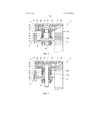
фиг. 1. Вид поперечного сечения структурного элемента согласно изобретению с возможностью его фиксации с помощью устройства согласно изобретению, состоящего из вклеенной в структурном элементе вставной детали и вывинчиваемого корректирующего дистанцию элемента, в фиксирующем элементе, причем корректирующий дистанцию элемент изображен на чертеже в дистанционном положении перед завинчиванием стяжного болта;FIG. 1. The cross-sectional view of the structural element according to the invention with the possibility of fixing it using the device according to the invention, consisting of an inserted part glued into the structural element and a screw-off distance-correcting element, in the fixing element, and the distance-correcting element is shown in the drawing in the remote position before screwing the coupling bolts;
фиг. 2. Соответствующий фиг. 1 вид поперечного сечения структурного элемента, причем корректирующий дистанцию элемент приведен при завертывании стяжного болта в положение упора в фиксирующем элементе;FIG. 2. Corresponding to FIG. 1 is a cross-sectional view of a structural element, wherein the distance-correcting element is shown while wrapping the coupling bolt in the stop position in the fixing element;
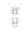
фиг. 3. Схематичный вид незначительно измененного по сравнению с фигурами 1, 2 устройства для соединения структурного элемента с фиксирующим элементом;FIG. 3. A schematic view of a device slightly changed in comparison with figures 1, 2 for connecting a structural element with a fixing element;
фиг. 4a. Продольный разрез согласно изобретению устройства в более коротком положении, соответствующем показанному на фиг. 1 дистанционному положению, а на фиг. 4b – продольный разрез согласно изобретению устройства в более длинном положении, соответствующем показанному на фиг. 2 положению упора;FIG. 4a. A longitudinal section according to the invention of the device in a shorter position corresponding to that shown in FIG. 1 to the remote position, and in FIG. 4b is a longitudinal section according to the invention of the device in a longer position corresponding to that shown in FIG. 2 position of the stop;
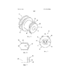
фиг. 5. Вид согласно изобретению устройства в направлении продольного отверстия корректирующего дистанцию элемента, причем в продольном отверстии расположен захватывающий элемент для фрикционно замкнутого соединения между стяжным болтом и корректирующим дистанцию элементом;FIG. 5. A view according to the invention of the device in the direction of the longitudinal hole of the distance-correcting element, and in the longitudinal hole there is a gripping element for a frictionally closed connection between the coupling bolt and the distance-correcting element;
фиг. 6. Вид захватывающего элемента согласно фиг. 5, выполненного в виде U-образного бюгельного элемента; иFIG. 6. View of the gripping element according to FIG. 5, made in the form of a U-shaped clasp element; and
фиг. 7. Вид сбоку захватывающего элемента согласно фигурам 5, 6.FIG. 7. Side view of the gripping element according to figures 5, 6.
На фиг. 1 показан структурный элемент, используемый в авиастроении для укладочного ящика. Структурный элемент 1 изготовлен, в частности, из волокнисто-усиленного композитного полимерного материала. В показанном примере выполнения структурный элемент имеет два расположенных под прямым углом друг к другу панельных элемента 2. На верхней стороне одного панельного элемента 2 на фиг. 1 показан материал 29 лицевой поверхности, например, фанера. Кроме того, предусмотрено устройство 4 для соединения структурного элемента 1 с фиксирующим элементом 5, установленным (на чертеже показан схематически) на структурном корпусе 30. Фиксирующий элемент 5 выполнен в показанном варианте выполнения в виде скобы или брекета, в котором установлена откидная гайка 6 с резьбой для завинчивания стяжного болта 7.In FIG. one Shows the structural element used in the aircraft industry for a laying box. The
Кроме того, как показано на фиг.1, устройство 4 имеет корректирующий дистанцию элемент 8, имеющий центральное продольное отверстие 9 для прохождения стяжного болта 7. Корректирующий дистанцию элемент 8 соединен с возможностью поворота посредством резьбового соединения 10 со вставной деталью 11. C этой целью вставная деталь 11 имеет внутреннюю резьбу, с которой согласована соответствующая наружная резьба корректирующего дистанцию элемента 8. В качестве вставной детали 11 предусмотрен в показанном выполнении втулочный элемент 11', имеющий внутреннюю резьбу для соединения с соответствующей наружной резьбой корректирующего дистанцию элемента 8.In addition, as shown in FIG. 1, the
Кроме того, на фиг. 1 показана вставная деталь 11, имеющая крепежный участок 12, расположенный полностью внутри выреза 13 структурного элемента 1. Вырез 13 производится при фрезеровании панельного элемента 2. Крепежный участок 12 вставной детали 11 соединен посредством клеевого соединения 14 со структурным элементом 1. In addition, in FIG. 1 shows an
Далее на фиг. 1, 2 виден расположенный в продольном отверстии 9 захватывающий элемент 16, сцепляемый при завертывании стяжного болта 7 с фрикционным замыканием со стяжным болтом 7. Вследствие этого корректирующий дистанцию элемент 8 можно переводить при завертывании стяжного болта 7 из дистанционного положения (ср. фиг. 1) в перекрывающее интервал между структурным элементом 1 и фиксирующим элементом 5 положение упора (ср. фиг. 2). В показанном примере выполнения корректирующий дистанцию элемент 8 вывинчивается при завертывании стяжного болта 7 из вставной детали 11. При этом устройство 4 переводится из дистанционного положения, соответствующего более короткому положению (ср. фиг. 4a), в котором корректирующий дистанцию элемент 8 немного выступает из вставной детали 11, в направлении фиксирующего элемента 5 в соответствующее положению упора в фиксирующем элементе 5 удлиненное положение (ср. фиг. 4b), в котором корректирующий дистанцию элемент 8 дальше выступает из вставной детали 11.Next, in FIG. 1, 2, the gripping
Кроме того, как это видно из фигур 1, 2 вставная деталь 11 имеет в крепежном участке 12 два крепежных фланца 17, предназначенные для склеивания со структурным элементом 1. Расположенные на ней параллельно и с интервалом друг к другу крепежные фланцы 17 продолжаются, по существу, вертикально к продольной оси продольного отверстия 9, или, по существу, вертикально к главной плоскости соответствующего панельного элемента 2. В выполнении согласно фигурам 1, 2 оба крепежных фланца 17 имеют по два отверстия 17', через которые можно заполнять клеем объем между крепежными фланцами 17. В соответствии с этим вставная деталь 11 соединена сбоку посредством клеевого соединения между крепежными фланцами 17 со структурным элементом 1. Крепежные фланцы 17 расположены между внешними поверхностями 1' структурного элемента 1. Следовательно, крепежный участок 12 полностью интегрирован в структурный элемент 1.In addition, as can be seen from figures 1, 2, the
На фигурах 3 - 7 показан другой вариант выполнения, отличающийся, по существу, от показанного на фигурах 1, 2 тем, что только верхний крепежный фланец 17 имеет отверстия 17' для внесения клея. Более того, отверстия 17' согласно фигурам 3 - 7 выполнены как расположенные напротив просечки во внешних краях крепежного фланца 17. Относительно остальных признаков вариант выполнения по фигурам 3 - 7 соответствует варианту по фигурам 1, 2, поэтому в этом отношении можно обращаться к предыдущим разъяснениям.Figures 3 to 7 show another embodiment, which differs essentially from that shown in figures 1, 2 in that only the upper mounting
Как показано на фигурах 3, 4, предусмотрены упоры для ограничения движения корректирующего дистанцию элемента 8 в осевом направлении относительно вставной детали 11. Для этого корректирующий дистанцию элемент 8 имеет с одной стороны приемные отверстия 18 для установки с возможностью отделения упорного элемента 19, с помощью которого в смонтированном положении предотвращается вывинчивание корректирующего дистанцию элемента 8 из вставной детали 11. В качестве упорного элемента 18 предусмотрен в показанном выполнении U-образный бюгельный элемент 19', вставляемый концами в расположенные напротив приемные отверстия 18 корректирующего дистанцию элемента 8. В смонтированном положении бюгельный элемент 19' выскакивает в продольное отверстие 9 корректирующего дистанцию элемента 8, поэтому блокируется движение корректирующего дистанцию элемента 8 с помощью прижатого к упорной поверхности 20 корректирующего дистанцию элемента 8 положения упора. Бюгельный элемент 19' выполнен из эластичного материала, поэтому выступающие концы сгибаются в смонтированном положении (ср. фиг. 3). Это предотвращает самопроизвольное высвобождение бюгельного элемента 19'. Более того, корректирующий дистанцию элемент 8 имеет на принятом во вставную деталь 11 конце упор 21, прижимающийся в положении устройства 4 с самым маленьким протяжением, в соответствии с дистанционным положением согласно фиг. 1, к соответствующему упору 22 вставной детали 11.As shown in figures 3, 4, stops are provided for restricting the movement of the distance-correcting
На фигурах 3 - 6 показан предусмотренный в виде захватывающего элемента 16 пружинный элемент 16', с возможностью упругой деформации при зацеплении со стяжным болтом 7. Пружинный элемент 16' прочен на кручение на фиксирующем участке 23 корректирующего дистанцию элемента 8 и расположен в осевом направлении неподвижно. В показанном примере выполнения пружинный элемент 16' имеет две, расположенные, по существу, параллельно друг к другу разжимные лапки 24, соединенные друг с другом посредством участка 25 соединения. Участок 25 соединения имеет две соединительные лапки 25', расположенные под тупым углом друг к другу. При завертывании стяжного болта 7 разжимные лапки 24 разжимаются, вследствие чего между стяжным болтом 7 и пружинным элементом 16' осуществляется фрикционное замыкание. Вследствие этого корректирующий дистанцию элемент 8 при завертывании стяжного болта 7 захватывается вместе в положение упора в фиксирующем элементе 5.Figures 3 - 6 show a spring element 16 'provided in the form of a
Как показано на фигурах 1 – 4, корректирующий дистанцию элемент 8 имеет на одном конце элемент 26 основания для прилегания к фиксирующему элементу 5, а на другом конце - головной элемент 27 с наружной резьбой для соединения с вставной деталью 11. Элемент основания 26 и головной элемент 27 соединены друг с другом посредством продольного участка 28 с меньшей, по сравнению с ними, площадью поперечного сечения.As shown in figures 1 to 4, the distance-correcting
Claims (15)
Applications Claiming Priority (3)
| Application Number | Priority Date | Filing Date | Title |
|---|---|---|---|
| ATA50167/2014A AT515304B1 (en) | 2014-03-07 | 2014-03-07 | Device for connecting a structural element and structural element |
| ATA50167/2014 | 2014-03-07 | ||
| PCT/AT2015/050060 WO2015131218A1 (en) | 2014-03-07 | 2015-03-06 | Device for connecting a structural element with a holding element spaced apart |
Publications (3)
| Publication Number | Publication Date |
|---|---|
| RU2016139262A RU2016139262A (en) | 2018-04-09 |
| RU2016139262A3 RU2016139262A3 (en) | 2018-07-25 |
| RU2680442C2 true RU2680442C2 (en) | 2019-02-21 |
Family
ID=52823961
Family Applications (1)
| Application Number | Title | Priority Date | Filing Date |
|---|---|---|---|
| RU2016139262A RU2680442C2 (en) | 2014-03-07 | 2015-03-06 | Device for connecting structural element with holding element spaced apart |
Country Status (9)
| Country | Link |
|---|---|
| US (1) | US10145399B2 (en) |
| EP (1) | EP3114359B1 (en) |
| CN (1) | CN106104015B (en) |
| AT (1) | AT515304B1 (en) |
| BR (1) | BR112016019903B1 (en) |
| CA (1) | CA2940485C (en) |
| ES (1) | ES2784845T3 (en) |
| RU (1) | RU2680442C2 (en) |
| WO (1) | WO2015131218A1 (en) |
Cited By (1)
| Publication number | Priority date | Publication date | Assignee | Title |
|---|---|---|---|---|
| RU2736343C1 (en) * | 2020-04-03 | 2020-11-16 | Федеральное государственное бюджетное образовательное учреждение высшего образования "Казанский государственный архитектурно-строительный университет" (КазГАСУ) | Bolted joint |
Families Citing this family (11)
| Publication number | Priority date | Publication date | Assignee | Title |
|---|---|---|---|---|
| DE202016105286U1 (en) * | 2016-09-22 | 2018-01-09 | Jörg Schwarzbich | Tolerance compensation element |
| US10836473B2 (en) * | 2017-10-24 | 2020-11-17 | Embraer S.A. | Mechanisms, systems and methods to allow step-ajdustment of aerodynamic surfaces |
| DE102017130998A1 (en) * | 2017-12-21 | 2019-06-27 | Böllhoff Verbindungstechnik GmbH | Mounting arrangement with angle compensation function |
| DE102018111049A1 (en) * | 2018-05-08 | 2019-11-14 | Böllhoff Verbindungstechnik GmbH | CONNECTION BETWEEN TWO TOLERANCE COMPONENT COMPONENTS AND A CONNECTING METHOD THEREFOR |
| GB2578115A (en) * | 2018-10-16 | 2020-04-22 | Airbus Operations Ltd | Modular attachment for leading and trailing edge structures |
| DE102019110201A1 (en) * | 2019-04-17 | 2020-10-22 | Witte Automotive Gmbh | Tolerance compensation device |
| CN110153947A (en) * | 2019-05-13 | 2019-08-23 | 上海佳慕汽车零部件有限公司 | A kind of tolerance automatic regulating apparatus |
| DE102020133763A1 (en) | 2020-12-16 | 2022-06-23 | Böllhoff Verbindungstechnik GmbH | tolerance compensation arrangement |
| CN113057461B (en) * | 2021-04-23 | 2022-06-21 | 东易日盛智能家居科技有限公司 | Stealthy composite board for furniture of connecting |
| PL4095395T3 (en) | 2021-05-27 | 2023-12-18 | Böllhoff Verbindungstechnik GmbH | Adjusting element, first component with adjusting element, connection structure comprising the first component, manufacturing method of the adjusting element and connection method |
| DE102021129082A1 (en) | 2021-11-09 | 2023-05-11 | Voith Patent Gmbh | Bushing device, system and method for reinforcing a through hole of a base material |
Citations (4)
| Publication number | Priority date | Publication date | Assignee | Title |
|---|---|---|---|---|
| WO1982000324A1 (en) * | 1980-07-24 | 1982-02-04 | Bard R | Aircraft floor panel installation system |
| DE10151383A1 (en) * | 2001-10-18 | 2003-04-30 | Boellhoff Gmbh | Tolerance compensation arrangement |
| RU2401949C2 (en) * | 2005-09-28 | 2010-10-20 | Эрбюс Франс | Device intended for attachment of light panel on support element |
| WO2013150016A1 (en) * | 2012-04-03 | 2013-10-10 | Böllhoff Verbindungstechnik GmbH | Fastening arrangement with tolerance compensation, and method for preassembly and assembly |
Family Cites Families (15)
| Publication number | Priority date | Publication date | Assignee | Title |
|---|---|---|---|---|
| US3510916A (en) * | 1965-06-21 | 1970-05-12 | Shur Lok Corp | Device for installing molded-in inserts in sandwich panels |
| US3606416A (en) * | 1970-02-11 | 1971-09-20 | Hi Shear Corp | Honeycomb fastener |
| US4981735A (en) * | 1989-09-05 | 1991-01-01 | The United States Of America As Represented By The Secretary Of The Army | Two piece threaded mounting insert with adhesive for use with honeycomb composite |
| US5288191A (en) * | 1991-08-26 | 1994-02-22 | Ewald Witte Gmbh & Co. Kg | Device for the clamping attachment of spaced structural parts |
| US5378099A (en) * | 1993-07-01 | 1995-01-03 | Gauron; Richard F. | Inset panel fastener with shoulder-engaging floating member |
| DE20313241U1 (en) * | 2003-08-27 | 2004-12-30 | Schwarzbich, Jörg | Device for connecting components with blind rivet attachment |
| DE10353376B4 (en) * | 2003-11-14 | 2005-09-08 | Airbus Deutschland Gmbh | Device and method for the mechanical connection of two components |
| DE202005009017U1 (en) * | 2005-06-08 | 2005-08-25 | Böllhoff Verbindungstechnik GmbH | Tolerance compensation device between two components consists of main part and adjusting sleeve, and separate driver part, all of thermoplastic material |
| DE102006034463B3 (en) * | 2006-07-26 | 2008-01-10 | A. Raymond Et Cie | Device for attaching an attachment and a support member at a distance from each other |
| DE202006012493U1 (en) * | 2006-08-14 | 2006-11-02 | Böllhoff Verbindungstechnik GmbH | Fastening device for fastening of one component to another with tolerance compensation has adjusting unit consisting of threaded sleeve and locating plate, wherein threaded sleeve is screwed into adjusting threaded nut of base unit |
| DE102007037242B4 (en) | 2006-08-14 | 2019-05-29 | Böllhoff Verbindungstechnik GmbH | Fastening device with tolerance compensation |
| DE202008011318U1 (en) * | 2008-08-28 | 2008-11-06 | Böllhoff Verbindungstechnik GmbH | Mounting arrangement with tolerance compensation |
| DE102008062894B4 (en) * | 2008-12-12 | 2011-07-21 | Hans und Ottmar Binder GbR (vertretungsberechtigte Gesellschafter: Hans Binder, 89558 Böhmenkirch; Ottmar Binder, 89558 Böhmenkirch), 89558 | Distance device and mounting arrangement with spacer |
| DE102008055526A1 (en) | 2008-12-15 | 2010-06-17 | Witte-Velbert Gmbh & Co. Kg | Device for twisted-connection of components by fastening screw, has supporting devices connected with components by bayonet joint, and screw-in thread assigned to blind-rivet nut, which is fixed with supporting devices by bayonet joint |
| KR101086609B1 (en) | 2009-06-01 | 2011-11-23 | 현대자동차주식회사 | Mounting structure of cowl cross bar |
-
2014
- 2014-03-07 AT ATA50167/2014A patent/AT515304B1/en not_active IP Right Cessation
-
2015
- 2015-03-06 CN CN201580012405.XA patent/CN106104015B/en active Active
- 2015-03-06 WO PCT/AT2015/050060 patent/WO2015131218A1/en active Application Filing
- 2015-03-06 CA CA2940485A patent/CA2940485C/en active Active
- 2015-03-06 US US15/124,008 patent/US10145399B2/en active Active
- 2015-03-06 EP EP15715664.7A patent/EP3114359B1/en active Active
- 2015-03-06 RU RU2016139262A patent/RU2680442C2/en active
- 2015-03-06 ES ES15715664T patent/ES2784845T3/en active Active
- 2015-03-06 BR BR112016019903-0A patent/BR112016019903B1/en active IP Right Grant
Patent Citations (4)
| Publication number | Priority date | Publication date | Assignee | Title |
|---|---|---|---|---|
| WO1982000324A1 (en) * | 1980-07-24 | 1982-02-04 | Bard R | Aircraft floor panel installation system |
| DE10151383A1 (en) * | 2001-10-18 | 2003-04-30 | Boellhoff Gmbh | Tolerance compensation arrangement |
| RU2401949C2 (en) * | 2005-09-28 | 2010-10-20 | Эрбюс Франс | Device intended for attachment of light panel on support element |
| WO2013150016A1 (en) * | 2012-04-03 | 2013-10-10 | Böllhoff Verbindungstechnik GmbH | Fastening arrangement with tolerance compensation, and method for preassembly and assembly |
Cited By (1)
| Publication number | Priority date | Publication date | Assignee | Title |
|---|---|---|---|---|
| RU2736343C1 (en) * | 2020-04-03 | 2020-11-16 | Федеральное государственное бюджетное образовательное учреждение высшего образования "Казанский государственный архитектурно-строительный университет" (КазГАСУ) | Bolted joint |
Also Published As
| Publication number | Publication date |
|---|---|
| AT515304A4 (en) | 2015-08-15 |
| US20170016464A1 (en) | 2017-01-19 |
| US10145399B2 (en) | 2018-12-04 |
| CN106104015A (en) | 2016-11-09 |
| AT515304B1 (en) | 2015-08-15 |
| BR112016019903B1 (en) | 2021-11-03 |
| RU2016139262A3 (en) | 2018-07-25 |
| CA2940485C (en) | 2019-05-21 |
| CA2940485A1 (en) | 2015-09-11 |
| CN106104015B (en) | 2018-12-28 |
| ES2784845T3 (en) | 2020-10-01 |
| RU2016139262A (en) | 2018-04-09 |
| EP3114359A1 (en) | 2017-01-11 |
| EP3114359B1 (en) | 2020-02-26 |
| WO2015131218A1 (en) | 2015-09-11 |
| BR112016019903A2 (en) | 2017-08-15 |
Similar Documents
| Publication | Publication Date | Title |
|---|---|---|
| RU2680442C2 (en) | Device for connecting structural element with holding element spaced apart | |
| US10378570B2 (en) | Securing pin for securing structural members | |
| US9377047B2 (en) | Through bolted connection hardware | |
| CA2183287C (en) | Concrete form spacing fixture | |
| KR20120092028A (en) | Tension clamp | |
| US20160053791A1 (en) | Attachment element | |
| US9470254B2 (en) | Combination having an anchor for panel-like components, and a fixing arrangement | |
| US20060280550A1 (en) | Profile connecting system | |
| HU220686B1 (en) | Fitting component | |
| KR101519849B1 (en) | Panel fixing structure for architecture | |
| KR100882567B1 (en) | Self locking type bolt system | |
| GB2500473A (en) | Handrail Connecting Device | |
| JP7511646B2 (en) | Anchor Assembly | |
| EP3333434B1 (en) | Wall fixings | |
| WO2013055240A1 (en) | An anchoring system | |
| KR101820438B1 (en) | Anchor Volt | |
| US11680598B2 (en) | Fixing device | |
| TW392031B (en) | Fitting component | |
| GB2044876A (en) | Fastening means | |
| CN103291705A (en) | Tube stock fastening connection fitting | |
| WO2023139396A2 (en) | Securing unit for securing load-bearing and thermal insulation elements to supporting structures | |
| KR20220075768A (en) | Bolt assembly | |
| KR20210054391A (en) | Semi-threaded one-touch coupler for rebar connection | |
| NL1019306C2 (en) | Connection method for securing two parts, e.g. panels to building framework, uses screw bolt surrounded by splayable spacer sleeve | |
| GB2539695A (en) | A bush and clamp assembly |