RU2679816C2 - Jewelry tool - Google Patents
Jewelry tool Download PDFInfo
- Publication number
- RU2679816C2 RU2679816C2 RU2016141866A RU2016141866A RU2679816C2 RU 2679816 C2 RU2679816 C2 RU 2679816C2 RU 2016141866 A RU2016141866 A RU 2016141866A RU 2016141866 A RU2016141866 A RU 2016141866A RU 2679816 C2 RU2679816 C2 RU 2679816C2
- Authority
- RU
- Russia
- Prior art keywords
- charm
- jewelry
- tool
- opening
- pendants
- Prior art date
Links
Images

Classifications
-
- B—PERFORMING OPERATIONS; TRANSPORTING
- B25—HAND TOOLS; PORTABLE POWER-DRIVEN TOOLS; MANIPULATORS
- B25B—TOOLS OR BENCH DEVICES NOT OTHERWISE PROVIDED FOR, FOR FASTENING, CONNECTING, DISENGAGING OR HOLDING
- B25B27/00—Hand tools, specially adapted for fitting together or separating parts or objects whether or not involving some deformation, not otherwise provided for
-
- A—HUMAN NECESSITIES
- A44—HABERDASHERY; JEWELLERY
- A44C—PERSONAL ADORNMENTS, e.g. JEWELLERY; COINS
- A44C25/00—Miscellaneous fancy ware for personal wear, e.g. pendants, crosses, crucifixes, charms
-
- A—HUMAN NECESSITIES
- A47—FURNITURE; DOMESTIC ARTICLES OR APPLIANCES; COFFEE MILLS; SPICE MILLS; SUCTION CLEANERS IN GENERAL
- A47G—HOUSEHOLD OR TABLE EQUIPMENT
- A47G25/00—Household implements used in connection with wearing apparel; Dress, hat or umbrella holders
- A47G25/90—Devices for domestic use for assisting in putting-on or pulling-off clothing, e.g. stockings or trousers
- A47G25/901—Devices for domestic use for assisting in putting-on or pulling-off clothing, e.g. stockings or trousers for bracelets
-
- B—PERFORMING OPERATIONS; TRANSPORTING
- B25—HAND TOOLS; PORTABLE POWER-DRIVEN TOOLS; MANIPULATORS
- B25B—TOOLS OR BENCH DEVICES NOT OTHERWISE PROVIDED FOR, FOR FASTENING, CONNECTING, DISENGAGING OR HOLDING
- B25B27/00—Hand tools, specially adapted for fitting together or separating parts or objects whether or not involving some deformation, not otherwise provided for
- B25B27/14—Hand tools, specially adapted for fitting together or separating parts or objects whether or not involving some deformation, not otherwise provided for for assembling objects other than by press fit or detaching same
-
- B—PERFORMING OPERATIONS; TRANSPORTING
- B25—HAND TOOLS; PORTABLE POWER-DRIVEN TOOLS; MANIPULATORS
- B25B—TOOLS OR BENCH DEVICES NOT OTHERWISE PROVIDED FOR, FOR FASTENING, CONNECTING, DISENGAGING OR HOLDING
- B25B3/00—Hand vices, i.e. vices intended to be held by hand; Pin vices
-
- B—PERFORMING OPERATIONS; TRANSPORTING
- B26—HAND CUTTING TOOLS; CUTTING; SEVERING
- B26D—CUTTING; DETAILS COMMON TO MACHINES FOR PERFORATING, PUNCHING, CUTTING-OUT, STAMPING-OUT OR SEVERING
- B26D3/00—Cutting work characterised by the nature of the cut made; Apparatus therefor
- B26D3/16—Cutting rods or tubes transversely
-
- A—HUMAN NECESSITIES
- A44—HABERDASHERY; JEWELLERY
- A44C—PERSONAL ADORNMENTS, e.g. JEWELLERY; COINS
- A44C25/00—Miscellaneous fancy ware for personal wear, e.g. pendants, crosses, crucifixes, charms
- A44C25/007—Charms or amulets
Abstract
Description
ОБЛАСТЬ ТЕХНИКИ, К КОТОРОЙ ОТНОСИТСЯ ИЗОБРЕТЕНИЕTECHNICAL FIELD TO WHICH INVENTION RELATES.
[0001] Настоящее изобретение относится к вспомогательным средствам для ношения ювелирных украшений, более конкретно, к вспомогательным средствам для закрепления и открепления соединителей, т.е. соединительных элементов ювелирных украшений и снятия декоративных подвесок, таких как блокируемые, т.е. застегиваемые на замок, подвески и предохранительные цепные затворы шарм-браслетов. [0001] the Present invention relates to auxiliary means for wearing jewelry, more specifically, to the auxiliary means for fastening and unfastening connectors, i.e. connecting elements of jewelry and the removal of decorative pendants, such as blocked, i.e. fastened with a lock, pendants and safety chain closures charm bracelets.
ОПИСАНИЕ ПРЕДШЕСТВУЮЩЕГО УРОВНЯ ТЕХНИКИDESCRIPTION OF PRIOR ART
[0002] Декоративные подвески, такие как блокируемые подвески и предохранительные замочки для цепочек, будучи установленными на браслет, надежно удерживаются на месте прочным зажимным элементом. Такие ювелирные изделия обычно называют европейскими цепочками или европейскими шарм-браслетами. Учитывая, что такие шарм-подвески часто бывают очень дорогими, нажимной элемент делают так, чтобы во избежание случайной потери его было трудно открыть и снять с шарм-браслета. Для дополнительного снижения риска случайной потери ценных шарм-подвесок многие браслеты снабжаются предохранительными цепочками и замочками. Более того, ювелирные украшения, такие как ожерелья, анклеты и браслеты, часто имеют соединители, которые трудно захватить руками, легко удерживаются в открытом положении и надежно защелкиваются. Это можно объяснить утонченной особенностью многих таких ювелирных украшений, требующих осторожного обращения, но процесс защелкивания ювелирных украшений далее усложняется ограничениями владельца и/или его помощника по успешной манипуляции соединителями ювелирных украшений и по их закреплению. [0002] Decorative pendants, such as lockable pendants and safety clasps for chains, when mounted on a bracelet, are securely held in place by a strong clamping element. Such jewelry is usually called European chains or European charm bracelets. Given that such charm pendants are often very expensive, the pressure element is made so that in order to avoid accidental loss it is difficult to open and remove it from the charm bracelet. To further reduce the risk of accidental loss of valuable charm pendants, many bracelets are supplied with safety chains and latches. Moreover, jewelry, such as necklaces, anklets and bracelets, often have connectors that are difficult to grip with your hands, easily held in the open position and securely snap into place. This can be explained by the sophisticated feature of many such jewelry that requires careful handling, but the process of snapping jewelry is further complicated by the limitations of the owner and / or his assistant for the successful manipulation and fastening of jewelry connectors.
[0003] Например, закрепление застежки типа "лобстер" или шпрингельного замка требует манипуляции рычажком, выступающим из кольцеобразного паза застежки, чтобы открыть или закрыть застежку. Может быть трудным визуально или путем осязания найти рычажок, манипулировать им и удерживать его в открытом положении относительно наклонной поверхности застежки. Человек, закрывающий застежку, должен поместить противоположный соединитель ювелирного изделия в узкую щель застежки и отпустить рычажок, чтобы закрепить соединители вместе. [0003] For example, fastening a lobster-type fastener or a spring lock requires manipulating a lever protruding from the annular groove of the fastener to open or close the fastener. It can be difficult visually or by touch to find the lever, manipulate it and hold it in the open position relative to the inclined surface of the fastener. The person closing the clasp must place the opposite connector of the jewelry into the narrow slit of the fastener and release the lever to secure the connectors together.
[0004] Сложные способы закрепления застежки и открытия шарм-подвески, чтобы соединить ее с шарм-браслетом или снять с шарм-браслета, могут осложняться неспособностью человека увидеть, совместить и закрепить вместе соединители ювелирного украшения. Открытие шарм-подвески руками практически невозможно. Узкая щель шарм-подвески настолько тонкая, что ноготь пальца может едва проходить по длине наружной поверхности подвески, чтобы достигнуть зажимного элемента в глубине изделия. Эти трудности были причинами того, что многие владельцы шарм-браслетов пытались защелкивать соединители опытным путем, ошибались и взламывали шарм-подвески с использованием средств, которые могут повреждать шарм-подвески и браслеты. Может быть достаточно досадно и опасно, когда пользователь прибегает к общедоступным острым предметам, таким как ножи и иглы, для открытия шарм-подвесок. [0004] Complicated ways of fastening a fastener and opening a charm pendant to connect it to a charm bracelet or to remove it from a charm bracelet may be complicated by the person's inability to see, combine and fasten jewelry connectors together. Opening the charm pendant with your hands is almost impossible. The narrow slit of the charm-suspension is so thin that the finger nail can barely pass along the length of the outer surface of the suspension in order to reach the clamping element in the depth of the product. These difficulties were the reasons that many owners of the charm bracelets tried to snap the connectors empirically, made mistakes and cracked the charm pendants using tools that could damage the charm pendants and bracelets. It can be quite annoying and dangerous when the user resorts to commonly available sharp objects, such as knives and needles, to open charm pendants.
[0005] Когда разрабатывались вспомогательные средства, способствующие открытию шарм-подвесок, их снятию с шарм-браслетов и закреплению соединителей ювелирных украшений, не было предложено средства удобного, гибкого в использовании, соответствующего запросам многих пользователей. Существует потребность в средстве для открывания декоративных шарм-подвесок и соединителей пружинного типа для ювелирных украшений без повреждения этих изделий. Настоящее изобретение удовлетворяет такую потребность. [0005] When ancillary tools were developed to facilitate the opening of the charm pendants, to remove them from the charm bracelets and to fasten jewelry connectors, no convenient, flexible to use means was proposed that would meet the needs of many users. There is a need for a tool for opening decorative charm pendants and spring-type connectors for jewelry without damaging these products. The present invention satisfies such a need.
СУЩНОСТЬ ИЗОБРЕТЕНИЯSUMMARY OF INVENTION
[0006] Целью настоящего изобретения является обеспечение экономичного устройства, приводимого в действие рукой, которое помогает открывать существующие декоративные шарм-подвески, такие как блокируемые подвески и предохранительные цепные затворы. Изобретение должно быть компактным, безопасным, прочным, легко изготовляемым и быть выполненным из стандартных материалов. Согласно настоящему изобретению корпус устройства состоит из двух основных рукояток, установленных поворотно в V-образном положении относительно друг друга. Рукоятки соединены между собой с одного конца, образуя соединенный конец, и начинают открываться с соединенного конца. [0006] The purpose of the present invention is to provide an economical hand-actuated device that helps to open existing decorative charm pendants, such as lockable pendants and safety chain closures. The invention must be compact, safe, durable, easy to manufacture and be made of standard materials. According to the present invention, the device body consists of two main handles pivotally mounted in a V-shaped position relative to each other. The handles are interconnected at one end, forming a connected end, and begin to open at the connected end.
[0007] Устройство содержит несколько уступов, по меньшей мере один из них выполнен дугообразным и предназначен для надежного удержания шарм-подвески на месте во время использования устройства для ее открытия при помощи рычажка. Форма и размеры уступов обеспечивают гибкость относительно форм и размеров шарм-подвесок, чтобы можно было использовать предлагаемое приспособление для открывания в соответствии с настоящим изобретением. По меньшей мере одна кромка с острым наконечником вставлена в одну из основных рукояток, чтобы облегчить открывание без повреждения шарм-подвески, которая может быть дорогим ювелирным изделием. [0007] the Device contains several ledges, at least one of them is made arcuate and is designed to securely hold the charm of the suspension in place during use of the device to open it with a lever. The shape and dimensions of the ledges provide flexibility with respect to the shapes and sizes of the charm pendants so that the proposed opening device according to the present invention can be used. At least one edge with a sharp tip is inserted into one of the main handles to facilitate opening without damaging the charm pendant, which can be an expensive piece of jewelry.
[0008] В одном из примеров осуществления настоящего изобретения пружинный элемент смещает первый конец первой рукоятки и второй рукоятки в общем направлении в стороны друг от друга. После передвижения первого конца первой рукоятки и второй рукоятки в направлении в стороны друг от друга, второй конец первой рукоятки и второй рукоятки перемещаются в общем направлении по направлению друг к другу. После того как второй конец первой рукоятки и второй рукоятки перемещаются навстречу друг другу, внутренняя поверхность первой рукоятки находится полностью напротив внутренней поверхности второй рукоятки. [0008] In one embodiment of the present invention, the spring member biases the first end of the first handle and the second handle in a common direction to the side of each other. After moving the first end of the first handle and the second handle in the direction away from each other, the second end of the first handle and the second handle move in a common direction towards each other. After the second end of the first handle and the second handle move towards each other, the inner surface of the first handle is completely opposite the inner surface of the second handle.
[0009] Один конец второй рукоятки содержит верхний дугообразный сегмент, содержащий, в свою очередь, наконечник, ориентированный так, чтобы обеспечивать значительный выигрыш в величине прилагаемого усилия при удержании шарм-подвески во время использования инструмента для ювелирных изделий в соответствии с настоящим изобретением. Вторая рукоятка далее включает вогнутую полость для размещения цепочек предохранительных цепных затворов во время использования инструмента для ювелирных изделий в соответствии с настоящим изобретением. Конструкция полости предназначена для предотвращения повреждения, которое в противном случае могло бы происходить при использовании инструмента. Инструмент в соответствии с настоящим изобретением устраняет недостатки существующих в настоящее время приспособлений для открывания и предлагает ![]()
![]()
[00010] Эти и другие преимущества одного или более аспектов будут очевидны при рассмотрении нижеследующего описания и прилагаемых чертежей. Хотя изложенное описание содержит специфичные особенности, их нельзя воспринимать как ограничивающие объем изобретения, они просто обеспечивают иллюстрацию некоторых из нескольких примеров осуществления изобретения. Таким образом, объем изобретения должен определяться скорее прилагаемой формулой изобретения и соответствующими юридическими эквивалентами, чем приведенными примерами. [00010] These and other advantages of one or more aspects will be apparent when considering the following description and the accompanying drawings. Although the description provided contains specific features, they cannot be taken as limiting the scope of the invention, they merely provide an illustration of some of the several embodiments of the invention. Thus, the scope of the invention should be determined rather by the attached claims and the corresponding legal equivalents than the examples given.
[00011] Нижеследующее описание изобретения вместе с прилагаемыми чертежами не должны восприниматься как ограничения изобретения показанными и описанными примерами, так как специалисты в данной области техники, к которой относится изобретение, могут разрабатывать другие формы данного изобретения в пределах, предусмотренных прилагаемой формулой. [00011] The following description of the invention, together with the accompanying drawings, should not be construed as limitations of the invention with the examples shown and described, as those skilled in the art to which the invention pertains can develop other forms of the invention within the limits provided by the appended claims.
ОПИСАНИЕ ЧЕРТЕЖЕЙDESCRIPTION OF THE DRAWINGS
[00012] Для более полного понимания настоящего изобретения приводится нижеследующее краткое описание в связи с прилагаемыми чертежами, номерами позиций и подробным описанием. [00012] For a more complete understanding of the present invention, the following brief description is provided in connection with the accompanying drawings, reference numbers and detailed description.
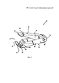
На Фиг. 1 изображен инструмент для ювелирных изделий в соответствии с настоящим изобретением, вид спереди в перспективе.FIG. 1 shows an instrument for jewelry in accordance with the present invention, a front perspective view.
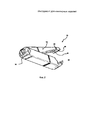
На Фиг. 2 изображен инструмент для ювелирных изделий в соответствии с настоящим изобретением, вид сзади в перспективе.FIG. 2 shows a tool for jewelry in accordance with the present invention, rear perspective view.
На Фиг. 3 изображен инструмент для ювелирных изделий в соответствии с настоящим изобретением, вид сбоку.FIG. 3 shows a tool for jewelry in accordance with the present invention, side view.
Ниже по тексту приводятся ссылки на примеры осуществления изобретения. Однако надо понимать, что изобретение не ограничивается конкретными описанными примерами. Наоборот, любая комбинация прилагаемых чертежей и элементов, относящихся или нет к различным примерам осуществления изобретения, рассматривается как использование изобретения. Более того, различные примеры осуществления изобретения обеспечивают много преимуществ по сравнению с известным уровнем техники. Хотя примеры осуществления изобретения могут обеспечивать преимущества по сравнению с другими возможными решениями и/или известным уровнем техники, конкретный пример осуществления не ограничивает изобретение, независимо от того, достигается или нет преимущество этим примером. Таким образом, приводимые ниже аспекты, признаки, примеры и преимущества являются просто иллюстративными и не считаются элементами или ограничениями прилагаемой формулы, за исключением тех, которые недвусмысленно излагаются в пунктах формулы. Таким же образом ссылка на "изобретение" не считается обобщением любой раскрываемой здесь сущности изобретения и не должна считаться элементами или ограничениями прилагаемой формулы, за исключением тех, которые недвусмысленно излагаются в пунктах формулы.Below are links to examples of the invention. However, it should be understood that the invention is not limited to the specific examples described. On the contrary, any combination of the accompanying drawings and elements relating or not to various embodiments of the invention is considered to be a use of the invention. Moreover, various embodiments of the invention provide many advantages over the prior art. Although embodiments of the invention may provide advantages over other possible solutions and / or prior art, a specific example of implementation does not limit the invention, regardless of whether an advantage is achieved or not. Thus, the following aspects, features, examples, and advantages are merely illustrative and are not considered to be elements or limitations of the appended claims, except those explicitly stated in the claims. In the same way, a reference to an “invention” is not considered to be a generalization of any essence of the invention disclosed herein and should not be considered as elements or restrictions of the attached formula, except for those explicitly stated in the claims.
Для простоты и ясности на фигурах чертежей показана конструкция в общем виде, описание и подробности широко известных признаков и технических средств могут опускаться, чтобы не затруднять понимание изобретения. Кроме того, элементы чертежей не обязательно выполняются в масштабе. Например, размеры некоторых элементов фигур могут быть увеличенными относительно других элементов, чтобы помочь пониманию примеров осуществления настоящего изобретения. Одинаковые номера позиций на различных фигурах обозначают одинаковые элементы.For simplicity and clarity, the figures in the drawings show the construction in general, the description and details of widely known features and technical means may be omitted so as not to obscure the understanding of the invention. In addition, drawing elements are not necessarily to scale. For example, the dimensions of some elements of the figures may be increased relative to other elements to help understanding the embodiments of the present invention. The same position numbers in different figures denote identical elements.
Термины "первый", "второй", "третий", "четвертый" и т.п. в описании и в формуле, если таковые имеются, используются для различения между похожими элементами и не обязательно для описания конкретного последовательного или хронологического порядка. Следует понимать, что используемые таким образом термины взаимозаменяемы при соответствующих условиях, например, когда описываемые примеры осуществления изобретения могут действовать в иной последовательности, чем это иллюстрируется здесь или иначе описываются здесь. Более того, термины "содержат" и "имеют" и любые их варианты охватывают неисключительное вхождение, например, когда процесс, способ, система, деталь, устройство или аппарат, содержащий перечень элементов, не обязательно ограничивается этими элементами, но может содержать другие элементы, не перечисленные в прямой форме или не являющиеся внутренне присущими такому процессу, способу, системе, детали, устройству или аппарату.The terms "first", "second", "third", "fourth", etc. in the description and in the formula, if any, are used to distinguish between similar elements and not necessarily to describe a particular sequential or chronological order. It should be understood that the terms used in this way are interchangeable under appropriate conditions, for example, when the described embodiments of the invention may act in a different order than is illustrated here or otherwise described here. Moreover, the terms “contain” and “have” and any variations thereof cover a non-exclusive occurrence, for example, when a process, method, system, part, device, or apparatus containing a list of elements is not necessarily limited to these elements, but may contain other elements not expressly listed or not intrinsic to such a process, method, system, part, device, or apparatus.
Термины "левый", "правый", "передний", "задний", "верхний", "нижний", "над", "под" и т.п. в описании и в формуле, если имеются, используются в иллюстративных целях и не обязательно для описания постоянных относительных положений. Следует понимать, что используемые таким образом термины взаимозаменяемы при соответствующих условиях, например, когда описываемые примеры осуществления изобретения могут действовать при иной ориентации, чем это иллюстрируется здесь или иначе описывается здесь.The terms "left", "right", "front", "rear", "upper", "lower", "above", "under", etc. in the description and in the formula, if any, are used for illustrative purposes and not necessarily to describe permanent relative positions. It should be understood that the terms used in this way are interchangeable under appropriate conditions, for example, when the described embodiments of the invention may operate with a different orientation than is illustrated here or otherwise described here.
Наконец, ссылка на "приспособление для открывания шарм-подвески" и "декоративная шарм-подвеска" делается в качестве примера, но не является ограничением. Инструмент для ювелирных изделий в соответствии с настоящим изобретением может использоваться для открывания цепочек на браслетах, ожерельях и анклетах. Более того, в данной отрасли известны ссылки на "декоративные шарм-подвески" как на "блокируемые подвески" или просто на "замки". В данной области техники известны также такие названия шарм-браслетов как "европейские шарм-браслеты" и "европейские цепочки". Соответственно приведенные ниже примеры предназначены не для ограничения объема изобретения, а для иллюстрации примеров осуществления изобретения.Finally, the reference to the “charm pendant opening device” and “decorative charm pendant” is made as an example, but is not a limitation. The jewelry tool of the present invention can be used to open chains on bracelets, necklaces, and anklets. Moreover, in this industry there are known references to “decorative charm pendants” as “lockable pendants” or simply “locks”. In this field of technology is also known such names charm bracelets as "European charm bracelets" and "European chains". Accordingly, the examples below are not intended to limit the scope of the invention, but to illustrate embodiments of the invention.
ПОДРОБНОЕ ОПИСАНИЕDETAILED DESCRIPTION
[00013] Ниже описываются иллюстративные примеры осуществления изобретения. Изложение служит для иллюстрации предпочтительных примеров осуществления изобретения, но не для ограничения изобретения. Нижеследующее объяснение дает конкретные подробности для полного понимания описания, достаточного для воспроизведения этих примеров изобретения. Специалисты в данной области техники поймут, что изобретение можно осуществить без таких подробностей. В иных случаях широко известные конструкции и функции не показываются или не описываются подробно, чтобы не затруднять понимание описания примеров осуществления изобретения. [00013] Illustrative embodiments of the invention are described below. The summary serves to illustrate preferred embodiments of the invention, but not to limit the invention. The following explanation provides specific details for fully understanding the description sufficient to reproduce these examples of the invention. Specialists in this field of technology will understand that the invention can be implemented without such details. In other cases, well-known structures and functions are not shown or are not described in detail in order not to complicate the understanding of the description of embodiments of the invention.
[00014] На Фиг. 1-3 для более подробного описания под позицией 10 показано устройство для открывания декоративных шарм-подвесок, блокируемых подвесок, предохранительных цепочек, а также застежек в соответствии с настоящим изобретением. Устройство 10 включает пару поворотно соединенных и расположенных близко друг к другу сжимаемых пальцами элементов 12 и 14. Каждый сжимаемый пальцами элемент 12 и 14 включает рукоятку 18, 20, соответственно, и рабочую часть 22, 24, соответственно. Верхняя рукоятка 18 немного уже нижней рукоятки 20, при этом рукоятки находятся на некотором расстоянии друг от друга на большей части их продольных осей таким образом, что одна рукоятка 18 может входить во вторую рукоятку 20, когда обе рукоятки 18 и 20 сжимаются вместе. В одном из примеров осуществления изобретения внешняя поверхность рукояток 18 и 20 может иметь покрытие, повышающее трение, чтобы облегчать захват рукояток пользователем. [00014] FIG. 1-3, for a more detailed description, under
[00015] Рабочие части 22, 24 сформованы как одно целое с соответствующими нажимными элементами 12 и 14. Поворотная ось 16, которая в одном из примеров осуществления изобретения может содержать шпильку, вставляется в соответствующие отверстия рукояток 18 и 20, обеспечивая таким образом возможность поворотного движения нажимных элементов 12 и 14. В одном из примеров осуществления изобретения усиленная пружина (не показана) поворотно соединяет между собой нажимные элементы 12 и 14. Усиленная пружина далее в процессе работы соединяет между собой нажимные элементы 12 и 14, проходя через поворотную ось 16 и обеспечивая сопротивление, достаточное для поддержания нажимных элементов 12 и 14 в V-образном положении, когда они сжимаются пользователем. [00015] The working
[00016] Устройство 10 в соответствии с настоящим изобретением содержит также практически клешнеобразный орган 50, открывающий шарм-подвеску. Одна его рабочая часть 24 снабжена вогнутой внутренней поверхностью 26. Канавка 30 выполнена в поверхности 26 и проходит от одной стороны 32 до другой стороны 34 рабочей части 24. Поверхность 26 выполнена вогнутой таким образом, чтобы шарм-подвеску или иное изделие, подлежащее открытию, можно было удерживать между искривлениями, проходящими от одной стороны 32 до другой стороны 34 рабочей части 24. Эта внутренняя поверхность 26 с возможностью перемещения вмещает шарм-подвеску или ее часть. В одном из примеров осуществления изобретения эта поверхность 26 может иметь остроугольную насечку 36. Остроугольная насечка 36 служит также для фиксации шарм-подвески или других изделий, подлежащих открытию, не допуская их проскальзывания во время открытия. [00016] The
[00017] Канавка 30 образует волнообразную впадину таким образом, чтобы цепочка предохранительного цепного затвора могла в ней помещаться при использовании устройства 10 в соответствии с настоящим изобретением. Канавка 30 предназначена для предотвращения повреждения, которое в ином случае могло бы происходить при использовании устройства 10. [00017] The
[00018] Одна рабочая часть 22 снабжена вскрывающим элементом 40 (см. Фиг. 2). Вскрывающий элемент 40 образован на поверхности, проходящей от одной стороны 42 до другой стороны 44 (Фиг. 1) рабочей части 22. В одном из примеров выполнения устройства 10 рабочая часть 22 с вскрывающим элементом 40 может иметь насечку. Остроугольная насечка 46 служит также для фиксации шарм-подвески и предотвращения ее вращения при использовании устройства 10. [00018] One working
[00019] Как более наглядно показано на Фиг. 2, внутренняя кромка первого нажимного элемента 12 имеет угловую острую кромку 40, которая также называется вскрывающим элементом. Угловая острая кромка 40 показана с углом примерно сорок пять градусов, но надо понимать, что эти угловые размеры служат только для целей иллюстрации, совсем не обязательно, чтобы острая кромка 40 имела угол сорок пять градусов. Острые кромки 40 могут быть сформованы под любым подходящим острым углом, чтобы они разделяли декоративные шарм-подвески и предохранительные цепные затворы или открывали застежки ювелирных украшений без нанесения им каких-либо повреждений. [00019] As illustrated more clearly in FIG. 2, the inner edge of the
[00020] Поворотная ось 16 позволяет рукояткам 18, 20 и рабочим частям 22, 24 перемещаться навстречу друг другу и отходить на некоторое расстояние друг от друга. Длина рукояток 18 и 20 выбирается такой, чтобы пользователю было удобно захватывать их большим и указательным пальцами, сохраняя достаточную степень контроля за поворотным движением рабочих частей 22, 24 для нажима на декоративные шарм-подвески, предохранительные цепочки или застежки с усилием, достаточным для открытия без нанесения каких-либо повреждений. [00020] The
[00021] Как описано выше, инструмент для ювелирных изделий 10 смещается в открытое положение, когда первый нажимной элемент 12 и второй нажимной элемент 14 соединены в одной точке относительно поворотной оси 16, придавая инструменту V-образную форму. В одном из примеров осуществления изобретения поворотная ось 16 содержит смещающий элемент, который обмотан вокруг шпильки (не показано) и который имеет концевые участки, способствующие перемещению нажимных элементов 12 и 14 на некоторое расстояние от центральной продольной оси X. Смещающий элемент может быть устройством хранения упругой энергии любой формы, обеспечивающим подходящее усилие для смещения нажимных элементов 12 и 14 в положение открытия, например, таким как листовая пружина или упругая полимерная конструкция. [00021] As described above, the tool for
[00022] Пользователь устанавливает рукоятки 18 и 20 в требуемое положение одной рукой, удерживая их между большим и указательным пальцами. Форма и размеры вскрывающего элемента 40 выбраны таким образом, чтобы помещаться в канавке декоративных шарм-подвесок, которые обычно имеются в шарм-браслетах. При использовании шарм-подвеска может находиться на внутренней вогнутой поверхности 26 с канавкой, направленной вверх в сторону вскрывающего элемента 40. Затем пользователь манипулирует рукоятками 18, 20 относительно шарм-подвески, чтобы разделить ее, или проводит вдоль канавки, которая является в основном сплошной линией. Когда к рукояткам 18 и 20 прилагается усилие, это обеспечивает вхождение вскрывающего элемента в канавку шарм-подвески между ее двумя сторонами и нажатие на элемент, соединяющий их. Это обеспечивает открывание шарм-подвески. [00022] The user sets the
[00023] Пользователь может легко остановить движение нажатия на рукоятки 18, 20, как только он определит, что шарм-подвеска открыта. Так как шарм-подвески могут иметь различные уровни сопротивления при нажимании на соединительный элемент, пользователь может предотвратить повреждение, остановив нажимание на рукоятки 18, 20. [00023] The user can easily stop the movement of pressing the
[00024] В одном из примеров осуществления изобретения на верхних кромках рукояток 18, 20 может быть образован контурированный элемент (не показан) для размещения большого пальца. Контурированный по форме большого пальца элемент может быть образован парой выступов, расположенных на некотором расстоянии друг от друга. Между выступами может быть образована выемка для помещения в ней большого и указательного пальцев. [00024] In one embodiment of the invention, a contoured element (not shown) may be formed on the upper edges of the
[00025] Хотя изобретение описано со ссылками на конкретные примеры его осуществления, для специалистов в данной области техники будет понятно, что могут быть сделаны различные изменения, не выходя за пределы объема изобретения. Соответственно, раскрытие примеров осуществления изобретения предназначено для иллюстрации объема изобретения, но не для ограничения объема. Предполагается, что объем изобретения будет ограничиваться только в тех случаях, когда это требуется прилагаемой формулой изобретения. Для специалиста в данной области техники будет очевидно, что обсуждаемые здесь устройства и способы могут быть реализованы в различных примерах осуществления изобретения и что нижеследующее обсуждение некоторых из этих примеров не обязательно представляет полное описание всех возможных примеров. Скорее, подробное описание чертежей и сами чертежи раскрывают, по крайней мере один предпочтительный пример и могут раскрывать альтернативные примеры. [00025] Although the invention has been described with reference to specific examples of its implementation, it will be clear to those skilled in the art that various changes can be made without departing from the scope of the invention. Accordingly, the disclosure of embodiments of the invention is intended to illustrate the scope of the invention, but not to limit the scope. It is assumed that the scope of the invention will be limited only in cases where it is required by the attached claims. It will be obvious to a person skilled in the art that the devices and methods discussed herein can be implemented in various embodiments of the invention and that the following discussion of some of these examples does not necessarily represent a complete description of all possible examples. Rather, the detailed description of the drawings and the drawings themselves disclose at least one preferred example and may disclose alternative examples.
[00026] Все элементы, на которые заявляются притязания в любом пункте формулы изобретения, являются существенными для примера осуществления изобретения, указанного в этом конкретном пункте. Следовательно, замена одного или нескольких элементов означает реконструкцию, а не ремонт. Кроме того, эффекты изобретения, преимущества и решения проблем описаны применительно к конкретным примерам осуществления изобретения. Эффекты изобретения, преимущества, решения проблем и любой элемент или элементы могут вызывать любые эффекты изобретения, преимущества и решения проблем, которые могут происходить более отчетливо или становиться более ярко выраженными, однако их нельзя интерпретировать как критичные, необходимые или существенные признаки любого пункта или всех пунктов формулы, если такие эффекты изобретения, преимущества, решения проблем или элементы не указаны в этих пунктах. [00026] All the elements claimed in any claim are essential to the exemplary embodiment of the invention specified in this particular clause. Consequently, replacing one or more elements means reconstruction, not repair. In addition, the effects of the invention, the advantages and solutions to problems are described with reference to specific embodiments of the invention. The effects of the invention, advantages, problem solving and any element or elements may cause any effects of the invention, advantages and solutions to problems that may occur more clearly or become more pronounced, but they cannot be interpreted as critical, necessary or essential features of any item or all items. formulas if such effects of the invention, advantages, solutions to problems or elements are not indicated in these clauses.
[00027] Более того, раскрытые здесь примеры осуществления изобретения и ограничения не передаются в общественное пользование в соответствии с доктриной передачи в общественное пользование, если примеры осуществления изобретения и/или ограничения: (1) не заявлены в прямой форме в пунктах формулы; (2) являются или потенциально могут являться эквивалентами ясно выраженных в формуле элементов и/или ограничений в соответствии с доктриной эквивалентов. [00027] Moreover, the embodiments and limitations disclosed herein are not transferred to public use in accordance with the public use doctrine, if examples of the implementation of the invention and / or limitations: (1) are not stated explicitly in the claims; (2) are or may potentially be equivalents of elements clearly expressed in the formula and / or restrictions in accordance with the doctrine of equivalents.
ВЫВОДЫ, РАМИФИКАЦИЯ И ОБЪЕМCONCLUSIONS, RAMIFICATION AND VOLUME
[00028] Несмотря на то, что проиллюстрирован и описан конкретный вариант изобретения, очевидно, что возможны различные модификации и изменения без отступления от сущности и объема изобретения. Например, инструмент для ювелирных изделий можно описывать как средство открытия декоративных шарм-подвесок, хотя изобретатель предполагает возможность использования инструмента для открытия различных других декоративных изделий, таких как застежки шарм-браслетов. Соответственно, изобретение не может чем-либо ограничиваться, за исключением пунктов прилагаемой формулы. [00028] Although a particular embodiment of the invention is illustrated and described, it is obvious that various modifications and changes are possible without departing from the spirit and scope of the invention. For example, a tool for jewelry can be described as a means of opening up decorative charm pendants, although the inventor suggests the possibility of using the tool to open various other decorative items, such as fasteners of charm bracelets. Accordingly, the invention cannot be limited to anything, except for the claims of the appended claims.
[00029] Предоставляемые здесь примеры могут использоваться в других системах, не обязательно тех, которые здесь описаны. Элементы и операции в различных примерах осуществления изобретения, описанные выше, могут комбинироваться для обеспечения дальнейших примеров осуществления изобретения. Все указанные выше патенты, патентные заявки и другие материалы, в том числе те, которые могут быть перечислены в документах, прилагаемых к заявке, включены в заявку путем отсылки. Особенности изобретения можно видоизменять, при необходимости, чтобы использовать системы, функции и концепции различных указанных выше прилагаемых документов, обеспечивая при этом дополнительные примеры осуществления настоящего изобретения. [00029] The examples provided here can be used in other systems, not necessarily those described here. The elements and operations in the various embodiments of the invention described above may be combined to provide further embodiments of the invention. All the above patents, patent applications and other materials, including those that may be listed in the documents attached to the application, are included in the application by reference. Features of the invention can be modified, if necessary, to use the systems, functions and concepts of the various above-mentioned documents, while providing additional examples of the implementation of the present invention.
[00030] Конкретная терминология, используемая для описания определенных признаков и особенностей изобретения, не должна означать, что она здесь переработана как ограничивающая конкретные характеристики, признаки или аспекты инструмента для ювелирных изделий, с которыми эта терминология связана. В целом, термины, используемые в нижеследующей формуле, не должны интерпретироваться, чтобы ограничивать инструмент для ювелирных изделий конкретными примерами осуществления, раскрытыми в описании, если в соответствующем разделе описания термины недвусмысленно это не определяют. Соответственно, фактический объем охватывает не только раскрытые примеры осуществления изобретения, но также все эквивалентные способы использования или реализации раскрытой системы. Выше приведенное описание примеров инструмента для ювелирных изделий не предполагалось быть исчерпывающим или ограниченным точными раскрытыми формами или конкретной областью использования. Несмотря на то, что в целях иллюстрации выше описаны конкретные примеры осуществления изобретения, возможны различные эквивалентные модификации, которые будут признаны специалистами в данной области техники. [00030] The specific terminology used to describe certain features and features of the invention should not mean that it has been reworked as limiting the specific characteristics, features or aspects of the jewelry tool with which this terminology is associated. In general, the terms used in the following formula should not be interpreted to limit the tool for jewelry to the specific examples of implementation disclosed in the description unless the terms clearly define this in the appropriate section of the description. Accordingly, the actual scope covers not only the disclosed embodiments, but also all equivalent ways of using or implementing the disclosed system. The above descriptions of examples of jewelry tools were not intended to be exhaustive or limited to precise open forms or a specific area of use. Although, for purposes of illustration, the specific embodiments of the invention have been described above, various equivalent modifications are possible that will be recognized by those skilled in the art.
[00031] Хотя определенные аспекты инструмента для ювелирных изделий представлены ниже в конкретных пунктах формулы, изобретатели предполагают различные аспекты системы в любом количестве пунктов. Соответственно, изобретатели оставляют за собой право вносить дополнительные пункты формулы после регистрации заявки, чтобы заявлять эти пункты для других аспектов инструмента для ювелирных изделий. [00031] Although certain aspects of the jewelry tool are presented below in specific claims, the inventors suggest various aspects of the system in any number of items. Accordingly, the inventors reserve the right to make additional claims after registration of the application in order to declare these points for other aspects of the tool for jewelry.
Applications Claiming Priority (3)
| Application Number | Priority Date | Filing Date | Title |
|---|---|---|---|
| US14/228,036 US9339920B2 (en) | 2014-03-27 | 2014-03-27 | Jewelry tool |
| US14/228,036 | 2014-03-27 | ||
| PCT/US2015/020004 WO2015148129A2 (en) | 2014-03-27 | 2015-03-11 | Jewelry tool |
Publications (3)
| Publication Number | Publication Date |
|---|---|
| RU2016141866A RU2016141866A (en) | 2018-04-27 |
| RU2016141866A3 RU2016141866A3 (en) | 2018-07-02 |
| RU2679816C2 true RU2679816C2 (en) | 2019-02-13 |
Family
ID=54189055
Family Applications (1)
| Application Number | Title | Priority Date | Filing Date |
|---|---|---|---|
| RU2016141866A RU2679816C2 (en) | 2014-03-27 | 2015-03-11 | Jewelry tool |
Country Status (9)
| Country | Link |
|---|---|
| US (1) | US9339920B2 (en) |
| EP (1) | EP3122522B1 (en) |
| JP (1) | JP2017514715A (en) |
| KR (1) | KR20160138539A (en) |
| CN (1) | CN106132644B (en) |
| AU (1) | AU2015236658A1 (en) |
| RU (1) | RU2679816C2 (en) |
| SG (1) | SG11201608885TA (en) |
| WO (1) | WO2015148129A2 (en) |
Families Citing this family (1)
| Publication number | Priority date | Publication date | Assignee | Title |
|---|---|---|---|---|
| US9439476B2 (en) * | 2014-06-23 | 2016-09-13 | Judith Ann Riccardi | Decorative ornament |
Citations (4)
| Publication number | Priority date | Publication date | Assignee | Title |
|---|---|---|---|---|
| US4787613A (en) * | 1987-04-13 | 1988-11-29 | Michael Hayes | Camera repair and support device |
| US6154964A (en) * | 1998-04-10 | 2000-12-05 | Lisle Corporation | Tube cutting tool |
| RU50464U1 (en) * | 2005-07-28 | 2006-01-20 | Олег Васильевич Поскотинов | PRESS FOR JEWELRY |
| RU134472U1 (en) * | 2013-05-07 | 2013-11-20 | Федеральное государственное бюджетное образовательное учреждение высшего профессионального образования "Тихоокеанский государственный университет" | DEVICE FOR PROCESSING JEWELRY |
Family Cites Families (29)
| Publication number | Priority date | Publication date | Assignee | Title |
|---|---|---|---|---|
| US2571819A (en) * | 1946-11-29 | 1951-10-16 | B H B Mfg Co Inc | Plier type shot splitting tool |
| US2618994A (en) * | 1949-05-20 | 1952-11-25 | Henry G Frazee | Shot splitting pliers |
| US2603849A (en) * | 1950-04-07 | 1952-07-22 | Guy J Epperson | Pivoted clasp |
| US2629114A (en) * | 1951-02-16 | 1953-02-24 | Theodore E Peterson | Cobbler's nippers |
| US2631411A (en) * | 1951-07-10 | 1953-03-17 | Louis A Pierson | Glass tube cutter |
| US2653332A (en) * | 1951-08-24 | 1953-09-29 | Harry H Precious | Fisherman's plier type shot splitting tool |
| US2753741A (en) * | 1954-04-01 | 1956-07-10 | Riley Specialty Inc | Fisherman's shot pliers |
| US2797019A (en) * | 1954-12-23 | 1957-06-25 | Edwin L Larson | Can opener for key strip cans |
| US2961670A (en) * | 1958-09-05 | 1960-11-29 | Jesse S Frame | Fisherman's tool |
| US3172319A (en) * | 1962-08-21 | 1965-03-09 | Stephen O Stanfield | Multi-purpose split shot pliers for fishermen |
| US3597775A (en) * | 1968-10-21 | 1971-08-10 | Diversified Electronics Co Inc | Product-forming tool |
| US3641654A (en) * | 1969-06-09 | 1972-02-15 | Raymond Ralph Wheeler | Split shot device |
| US4057863A (en) * | 1975-09-12 | 1977-11-15 | Bewley Homer G | Plier assembly |
| DE3606017C1 (en) * | 1986-02-25 | 1987-09-17 | Hans Hackner Prototypen Gmbh | Handheld device for opening glass ampoules |
| US4796318A (en) * | 1987-11-12 | 1989-01-10 | Bigej Albert L | Fisherman's pliers |
| US5557874A (en) * | 1994-06-09 | 1996-09-24 | Pietrandrea; Samuel J. | Multi-purpose fishing tool |
| CA2274034C (en) * | 1999-06-03 | 2007-04-24 | Michael L. Scheuerman | Crimped-ring removal device |
| DE19957015A1 (en) * | 1999-11-26 | 2001-06-28 | Werner Koch | Device for dividing tablets comprises a blade or a similar element which in the final state of the device is located centrally over the tablet to be divided |
| US7254854B2 (en) * | 2003-03-12 | 2007-08-14 | Kimio Yonenoi | Multi-functional compact line clipper for fishing |
| US7010880B1 (en) * | 2004-09-08 | 2006-03-14 | Meiseles Steven H | Split shot attachment and removal tool |
| US7013594B1 (en) * | 2004-09-08 | 2006-03-21 | Meiseles Steven H | Pivoting split shot attachment and removal tool |
| JP3113063U (en) * | 2005-05-11 | 2005-09-02 | 逸生 礒崎 | Necklace and other decorative accessories |
| CN100335243C (en) * | 2005-12-15 | 2007-09-05 | 上海应用技术学院 | Multifunctional sugarcane cutting knife |
| DE202006019957U1 (en) * | 2006-02-16 | 2007-07-26 | Jabbusch, Wolfgang | Device for crushing tablets comprises pivoting arms connected together by a hinge so that the lower arm has a support surface lying opposite the free end of the upper arm close to its free end |
| US7784383B2 (en) * | 2007-01-12 | 2010-08-31 | Peter Salva | Jewelry aid |
| JP3134264U (en) * | 2007-05-28 | 2007-08-09 | 隼人 野口 | Control tool for decoration |
| CN201086305Y (en) * | 2007-09-10 | 2008-07-16 | 陈重道 | Multifunctional plastic-aluminum tube scissors |
| US20110010867A1 (en) * | 2009-07-15 | 2011-01-20 | Bihl-Luark Dolores A | Specialized compressing and opening tool for charm bracelet |
| CN201711993U (en) * | 2010-07-09 | 2011-01-19 | 杨长国 | Aluminum plastic pipe scissors with main and auxiliary cutting edges |
-
2014
- 2014-03-27 US US14/228,036 patent/US9339920B2/en active Active
-
2015
- 2015-03-11 JP JP2017502753A patent/JP2017514715A/en active Pending
- 2015-03-11 WO PCT/US2015/020004 patent/WO2015148129A2/en active Application Filing
- 2015-03-11 AU AU2015236658A patent/AU2015236658A1/en not_active Abandoned
- 2015-03-11 EP EP15769165.0A patent/EP3122522B1/en active Active
- 2015-03-11 SG SG11201608885TA patent/SG11201608885TA/en unknown
- 2015-03-11 CN CN201580016815.1A patent/CN106132644B/en active Active
- 2015-03-11 KR KR1020167030170A patent/KR20160138539A/en unknown
- 2015-03-11 RU RU2016141866A patent/RU2679816C2/en active
Patent Citations (4)
| Publication number | Priority date | Publication date | Assignee | Title |
|---|---|---|---|---|
| US4787613A (en) * | 1987-04-13 | 1988-11-29 | Michael Hayes | Camera repair and support device |
| US6154964A (en) * | 1998-04-10 | 2000-12-05 | Lisle Corporation | Tube cutting tool |
| RU50464U1 (en) * | 2005-07-28 | 2006-01-20 | Олег Васильевич Поскотинов | PRESS FOR JEWELRY |
| RU134472U1 (en) * | 2013-05-07 | 2013-11-20 | Федеральное государственное бюджетное образовательное учреждение высшего профессионального образования "Тихоокеанский государственный университет" | DEVICE FOR PROCESSING JEWELRY |
Also Published As
| Publication number | Publication date |
|---|---|
| WO2015148129A3 (en) | 2015-11-19 |
| RU2016141866A3 (en) | 2018-07-02 |
| RU2016141866A (en) | 2018-04-27 |
| CN106132644B (en) | 2019-08-09 |
| US9339920B2 (en) | 2016-05-17 |
| WO2015148129A2 (en) | 2015-10-01 |
| CN106132644A (en) | 2016-11-16 |
| JP2017514715A (en) | 2017-06-08 |
| SG11201608885TA (en) | 2016-12-29 |
| EP3122522A4 (en) | 2017-11-29 |
| KR20160138539A (en) | 2016-12-05 |
| EP3122522A2 (en) | 2017-02-01 |
| AU2015236658A1 (en) | 2016-11-10 |
| EP3122522B1 (en) | 2019-06-05 |
| US20150273672A1 (en) | 2015-10-01 |
Similar Documents
| Publication | Publication Date | Title |
|---|---|---|
| EP2435651B1 (en) | Safety handcuff for the easy placement thereof on an individual | |
| CH629944A5 (en) | CLOSING DEVICE. | |
| US7784383B2 (en) | Jewelry aid | |
| US20090090379A1 (en) | Locking clip | |
| JP2010029678A (en) | Hair clip | |
| EP2995214B1 (en) | Opening implement for accessory catch | |
| RU2679816C2 (en) | Jewelry tool | |
| JP6782495B2 (en) | Pruning scissors that combine the functions of pruning and buffering | |
| US20140084615A1 (en) | Locking tong | |
| US4788768A (en) | Nail clipper with guard means | |
| JP6030428B2 (en) | Fish pincer | |
| US20030121526A1 (en) | Hair clip | |
| US2750826A (en) | pliers | |
| US5884953A (en) | Gripping device | |
| KR20170108628A (en) | Scissors having tongs | |
| WO2016162621A1 (en) | Pair of scissors, particularly for cutting hair | |
| JP5725633B2 (en) | Accessory fastener release tool | |
| TWM580497U (en) | Hook structure for tool | |
| AU2013100060A4 (en) | A utensil | |
| JP3194666U (en) | Weeding tool | |
| US365614A (en) | Lightbown | |
| TW202122044A (en) | Handle with slide-opening structure | |
| TWM574823U (en) | Pressing actuation mechanism for lopper | |
| KR20000020348U (en) | Interval-Controlable Pincers | |
| JP2001078501A (en) | Weeding utensil |