RU2677418C2 - System with telecommunication element, masked reflective constructive element, containing multilayer optical polymeric film - Google Patents
System with telecommunication element, masked reflective constructive element, containing multilayer optical polymeric film Download PDFInfo
- Publication number
- RU2677418C2 RU2677418C2 RU2017117305A RU2017117305A RU2677418C2 RU 2677418 C2 RU2677418 C2 RU 2677418C2 RU 2017117305 A RU2017117305 A RU 2017117305A RU 2017117305 A RU2017117305 A RU 2017117305A RU 2677418 C2 RU2677418 C2 RU 2677418C2
- Authority
- RU
- Russia
- Prior art keywords
- multilayer optical
- polymer film
- optical polymer
- layer
- film
- Prior art date
Links
Images
Classifications
-
- H—ELECTRICITY
- H01—ELECTRIC ELEMENTS
- H01Q—ANTENNAS, i.e. RADIO AERIALS
- H01Q1/00—Details of, or arrangements associated with, antennas
- H01Q1/40—Radiating elements coated with or embedded in protective material
-
- B—PERFORMING OPERATIONS; TRANSPORTING
- B32—LAYERED PRODUCTS
- B32B—LAYERED PRODUCTS, i.e. PRODUCTS BUILT-UP OF STRATA OF FLAT OR NON-FLAT, e.g. CELLULAR OR HONEYCOMB, FORM
- B32B27/00—Layered products comprising a layer of synthetic resin
- B32B27/06—Layered products comprising a layer of synthetic resin as the main or only constituent of a layer, which is next to another layer of the same or of a different material
- B32B27/08—Layered products comprising a layer of synthetic resin as the main or only constituent of a layer, which is next to another layer of the same or of a different material of synthetic resin
-
- B—PERFORMING OPERATIONS; TRANSPORTING
- B32—LAYERED PRODUCTS
- B32B—LAYERED PRODUCTS, i.e. PRODUCTS BUILT-UP OF STRATA OF FLAT OR NON-FLAT, e.g. CELLULAR OR HONEYCOMB, FORM
- B32B27/00—Layered products comprising a layer of synthetic resin
- B32B27/18—Layered products comprising a layer of synthetic resin characterised by the use of special additives
- B32B27/26—Layered products comprising a layer of synthetic resin characterised by the use of special additives using curing agents
-
- B—PERFORMING OPERATIONS; TRANSPORTING
- B32—LAYERED PRODUCTS
- B32B—LAYERED PRODUCTS, i.e. PRODUCTS BUILT-UP OF STRATA OF FLAT OR NON-FLAT, e.g. CELLULAR OR HONEYCOMB, FORM
- B32B27/00—Layered products comprising a layer of synthetic resin
- B32B27/30—Layered products comprising a layer of synthetic resin comprising vinyl (co)polymers; comprising acrylic (co)polymers
- B32B27/304—Layered products comprising a layer of synthetic resin comprising vinyl (co)polymers; comprising acrylic (co)polymers comprising vinyl halide (co)polymers, e.g. PVC, PVDC, PVF, PVDF
-
- B—PERFORMING OPERATIONS; TRANSPORTING
- B32—LAYERED PRODUCTS
- B32B—LAYERED PRODUCTS, i.e. PRODUCTS BUILT-UP OF STRATA OF FLAT OR NON-FLAT, e.g. CELLULAR OR HONEYCOMB, FORM
- B32B27/00—Layered products comprising a layer of synthetic resin
- B32B27/30—Layered products comprising a layer of synthetic resin comprising vinyl (co)polymers; comprising acrylic (co)polymers
- B32B27/308—Layered products comprising a layer of synthetic resin comprising vinyl (co)polymers; comprising acrylic (co)polymers comprising acrylic (co)polymers
-
- B—PERFORMING OPERATIONS; TRANSPORTING
- B32—LAYERED PRODUCTS
- B32B—LAYERED PRODUCTS, i.e. PRODUCTS BUILT-UP OF STRATA OF FLAT OR NON-FLAT, e.g. CELLULAR OR HONEYCOMB, FORM
- B32B27/00—Layered products comprising a layer of synthetic resin
- B32B27/32—Layered products comprising a layer of synthetic resin comprising polyolefins
- B32B27/322—Layered products comprising a layer of synthetic resin comprising polyolefins comprising halogenated polyolefins, e.g. PTFE
-
- B—PERFORMING OPERATIONS; TRANSPORTING
- B32—LAYERED PRODUCTS
- B32B—LAYERED PRODUCTS, i.e. PRODUCTS BUILT-UP OF STRATA OF FLAT OR NON-FLAT, e.g. CELLULAR OR HONEYCOMB, FORM
- B32B27/00—Layered products comprising a layer of synthetic resin
- B32B27/36—Layered products comprising a layer of synthetic resin comprising polyesters
-
- B—PERFORMING OPERATIONS; TRANSPORTING
- B32—LAYERED PRODUCTS
- B32B—LAYERED PRODUCTS, i.e. PRODUCTS BUILT-UP OF STRATA OF FLAT OR NON-FLAT, e.g. CELLULAR OR HONEYCOMB, FORM
- B32B3/00—Layered products comprising a layer with external or internal discontinuities or unevennesses, or a layer of non-planar form; Layered products having particular features of form
- B32B3/02—Layered products comprising a layer with external or internal discontinuities or unevennesses, or a layer of non-planar form; Layered products having particular features of form characterised by features of form at particular places, e.g. in edge regions
- B32B3/08—Layered products comprising a layer with external or internal discontinuities or unevennesses, or a layer of non-planar form; Layered products having particular features of form characterised by features of form at particular places, e.g. in edge regions characterised by added members at particular parts
-
- G—PHYSICS
- G02—OPTICS
- G02B—OPTICAL ELEMENTS, SYSTEMS OR APPARATUS
- G02B5/00—Optical elements other than lenses
- G02B5/08—Mirrors
-
- H—ELECTRICITY
- H01—ELECTRIC ELEMENTS
- H01Q—ANTENNAS, i.e. RADIO AERIALS
- H01Q1/00—Details of, or arrangements associated with, antennas
- H01Q1/44—Details of, or arrangements associated with, antennas using equipment having another main function to serve additionally as an antenna, e.g. means for giving an antenna an aesthetic aspect
-
- H—ELECTRICITY
- H01—ELECTRIC ELEMENTS
- H01Q—ANTENNAS, i.e. RADIO AERIALS
- H01Q19/00—Combinations of primary active antenna elements and units with secondary devices, e.g. with quasi-optical devices, for giving the antenna a desired directional characteristic
- H01Q19/10—Combinations of primary active antenna elements and units with secondary devices, e.g. with quasi-optical devices, for giving the antenna a desired directional characteristic using reflecting surfaces
- H01Q19/18—Combinations of primary active antenna elements and units with secondary devices, e.g. with quasi-optical devices, for giving the antenna a desired directional characteristic using reflecting surfaces having two or more spaced reflecting surfaces
-
- B—PERFORMING OPERATIONS; TRANSPORTING
- B32—LAYERED PRODUCTS
- B32B—LAYERED PRODUCTS, i.e. PRODUCTS BUILT-UP OF STRATA OF FLAT OR NON-FLAT, e.g. CELLULAR OR HONEYCOMB, FORM
- B32B2250/00—Layers arrangement
- B32B2250/24—All layers being polymeric
- B32B2250/246—All polymers belonging to those covered by groups B32B27/32 and B32B27/30
-
- B—PERFORMING OPERATIONS; TRANSPORTING
- B32—LAYERED PRODUCTS
- B32B—LAYERED PRODUCTS, i.e. PRODUCTS BUILT-UP OF STRATA OF FLAT OR NON-FLAT, e.g. CELLULAR OR HONEYCOMB, FORM
- B32B2255/00—Coating on the layer surface
- B32B2255/10—Coating on the layer surface on synthetic resin layer or on natural or synthetic rubber layer
-
- B—PERFORMING OPERATIONS; TRANSPORTING
- B32—LAYERED PRODUCTS
- B32B—LAYERED PRODUCTS, i.e. PRODUCTS BUILT-UP OF STRATA OF FLAT OR NON-FLAT, e.g. CELLULAR OR HONEYCOMB, FORM
- B32B2255/00—Coating on the layer surface
- B32B2255/20—Inorganic coating
-
- B—PERFORMING OPERATIONS; TRANSPORTING
- B32—LAYERED PRODUCTS
- B32B—LAYERED PRODUCTS, i.e. PRODUCTS BUILT-UP OF STRATA OF FLAT OR NON-FLAT, e.g. CELLULAR OR HONEYCOMB, FORM
- B32B2255/00—Coating on the layer surface
- B32B2255/26—Polymeric coating
-
- B—PERFORMING OPERATIONS; TRANSPORTING
- B32—LAYERED PRODUCTS
- B32B—LAYERED PRODUCTS, i.e. PRODUCTS BUILT-UP OF STRATA OF FLAT OR NON-FLAT, e.g. CELLULAR OR HONEYCOMB, FORM
- B32B2264/00—Composition or properties of particles which form a particulate layer or are present as additives
-
- B—PERFORMING OPERATIONS; TRANSPORTING
- B32—LAYERED PRODUCTS
- B32B—LAYERED PRODUCTS, i.e. PRODUCTS BUILT-UP OF STRATA OF FLAT OR NON-FLAT, e.g. CELLULAR OR HONEYCOMB, FORM
- B32B2264/00—Composition or properties of particles which form a particulate layer or are present as additives
- B32B2264/10—Inorganic particles
-
- B—PERFORMING OPERATIONS; TRANSPORTING
- B32—LAYERED PRODUCTS
- B32B—LAYERED PRODUCTS, i.e. PRODUCTS BUILT-UP OF STRATA OF FLAT OR NON-FLAT, e.g. CELLULAR OR HONEYCOMB, FORM
- B32B2270/00—Resin or rubber layer containing a blend of at least two different polymers
-
- B—PERFORMING OPERATIONS; TRANSPORTING
- B32—LAYERED PRODUCTS
- B32B—LAYERED PRODUCTS, i.e. PRODUCTS BUILT-UP OF STRATA OF FLAT OR NON-FLAT, e.g. CELLULAR OR HONEYCOMB, FORM
- B32B2274/00—Thermoplastic elastomer material
-
- B—PERFORMING OPERATIONS; TRANSPORTING
- B32—LAYERED PRODUCTS
- B32B—LAYERED PRODUCTS, i.e. PRODUCTS BUILT-UP OF STRATA OF FLAT OR NON-FLAT, e.g. CELLULAR OR HONEYCOMB, FORM
- B32B2307/00—Properties of the layers or laminate
- B32B2307/40—Properties of the layers or laminate having particular optical properties
- B32B2307/416—Reflective
-
- B—PERFORMING OPERATIONS; TRANSPORTING
- B32—LAYERED PRODUCTS
- B32B—LAYERED PRODUCTS, i.e. PRODUCTS BUILT-UP OF STRATA OF FLAT OR NON-FLAT, e.g. CELLULAR OR HONEYCOMB, FORM
- B32B2307/00—Properties of the layers or laminate
- B32B2307/40—Properties of the layers or laminate having particular optical properties
- B32B2307/418—Refractive
-
- B—PERFORMING OPERATIONS; TRANSPORTING
- B32—LAYERED PRODUCTS
- B32B—LAYERED PRODUCTS, i.e. PRODUCTS BUILT-UP OF STRATA OF FLAT OR NON-FLAT, e.g. CELLULAR OR HONEYCOMB, FORM
- B32B2307/00—Properties of the layers or laminate
- B32B2307/40—Properties of the layers or laminate having particular optical properties
- B32B2307/42—Polarizing, birefringent, filtering
-
- B—PERFORMING OPERATIONS; TRANSPORTING
- B32—LAYERED PRODUCTS
- B32B—LAYERED PRODUCTS, i.e. PRODUCTS BUILT-UP OF STRATA OF FLAT OR NON-FLAT, e.g. CELLULAR OR HONEYCOMB, FORM
- B32B2307/00—Properties of the layers or laminate
- B32B2307/50—Properties of the layers or laminate having particular mechanical properties
- B32B2307/554—Wear resistance
-
- B—PERFORMING OPERATIONS; TRANSPORTING
- B32—LAYERED PRODUCTS
- B32B—LAYERED PRODUCTS, i.e. PRODUCTS BUILT-UP OF STRATA OF FLAT OR NON-FLAT, e.g. CELLULAR OR HONEYCOMB, FORM
- B32B2307/00—Properties of the layers or laminate
- B32B2307/70—Other properties
- B32B2307/71—Resistive to light or to UV
-
- B—PERFORMING OPERATIONS; TRANSPORTING
- B32—LAYERED PRODUCTS
- B32B—LAYERED PRODUCTS, i.e. PRODUCTS BUILT-UP OF STRATA OF FLAT OR NON-FLAT, e.g. CELLULAR OR HONEYCOMB, FORM
- B32B2307/00—Properties of the layers or laminate
- B32B2307/70—Other properties
- B32B2307/714—Inert, i.e. inert to chemical degradation, corrosion
-
- B—PERFORMING OPERATIONS; TRANSPORTING
- B32—LAYERED PRODUCTS
- B32B—LAYERED PRODUCTS, i.e. PRODUCTS BUILT-UP OF STRATA OF FLAT OR NON-FLAT, e.g. CELLULAR OR HONEYCOMB, FORM
- B32B2307/00—Properties of the layers or laminate
- B32B2307/70—Other properties
- B32B2307/732—Dimensional properties
-
- B—PERFORMING OPERATIONS; TRANSPORTING
- B32—LAYERED PRODUCTS
- B32B—LAYERED PRODUCTS, i.e. PRODUCTS BUILT-UP OF STRATA OF FLAT OR NON-FLAT, e.g. CELLULAR OR HONEYCOMB, FORM
- B32B2405/00—Adhesive articles, e.g. adhesive tapes
-
- B—PERFORMING OPERATIONS; TRANSPORTING
- B32—LAYERED PRODUCTS
- B32B—LAYERED PRODUCTS, i.e. PRODUCTS BUILT-UP OF STRATA OF FLAT OR NON-FLAT, e.g. CELLULAR OR HONEYCOMB, FORM
- B32B2457/00—Electrical equipment
-
- B—PERFORMING OPERATIONS; TRANSPORTING
- B32—LAYERED PRODUCTS
- B32B—LAYERED PRODUCTS, i.e. PRODUCTS BUILT-UP OF STRATA OF FLAT OR NON-FLAT, e.g. CELLULAR OR HONEYCOMB, FORM
- B32B2551/00—Optical elements
-
- B—PERFORMING OPERATIONS; TRANSPORTING
- B32—LAYERED PRODUCTS
- B32B—LAYERED PRODUCTS, i.e. PRODUCTS BUILT-UP OF STRATA OF FLAT OR NON-FLAT, e.g. CELLULAR OR HONEYCOMB, FORM
- B32B2571/00—Protective equipment
-
- G—PHYSICS
- G02—OPTICS
- G02B—OPTICAL ELEMENTS, SYSTEMS OR APPARATUS
- G02B5/00—Optical elements other than lenses
- G02B5/08—Mirrors
- G02B5/0816—Multilayer mirrors, i.e. having two or more reflecting layers
- G02B5/0825—Multilayer mirrors, i.e. having two or more reflecting layers the reflecting layers comprising dielectric materials only
- G02B5/0841—Multilayer mirrors, i.e. having two or more reflecting layers the reflecting layers comprising dielectric materials only comprising organic materials, e.g. polymers
Abstract
Description
Область техникиTechnical field
Настоящее изобретение относится к системе с замаскированным телекоммуникационным элементом и способу маскировки телекоммуникационного элемента.The present invention relates to a system with a disguised telecommunications element and a method for masking a telecommunications element.
Уровень техникиState of the art
Поскольку количество абонентов беспроводной связи продолжает расти чрезвычайно высокими темпами, также увеличивается поток данных беспроводной связи. Распространение новых интеллектуальных устройств также ускоряет рост потока данных беспроводной связи. Увеличивается количество мультимедийных приложений, таких как потоковая передача видео, в областях с высокой плотностью населения. Чтобы не отставать от новых потребностей необходимо увеличение пропускной способности и количества узлов сотовой связи. Чтобы соответствовать требованиям к полосе пропускания согласно географическому положению, операторы связи стремятся добавлять дополнительные узлы в виде макросот и использовать технологию малых сот для увеличения пропускной способности. Малые соты могут быть развернуты внутри или снаружи помещений.As the number of wireless subscribers continues to grow at an extremely fast pace, the flow of wireless data is also increasing. The proliferation of new smart devices is also accelerating the growth of wireless data flow. The number of multimedia applications, such as video streaming, is increasing in areas of high population density. In order to keep up with new needs, it is necessary to increase the throughput and the number of cellular communication nodes. In order to meet the bandwidth requirements according to geographical location, telecom operators are striving to add additional nodes in the form of macro cells and use small cell technology to increase throughput. Small cells can be deployed indoors or outdoors.
Одной из задач, связанных с развертыванием узлов в виде макросот и малых сот, является обеспечение эстетического вида такого оборудования. Например, планировщики сети должны принимать в расчет внешний вид макросот, развернутых на крышах зданий, а также инфраструктуру устанавливаемых дополнительных малых сот. Таким образом, существует необходимость в улучшении эстетического вида, связанного с узлами в виде макросот и малых сот, а также других телекоммуникационных элементов, развертываемых в настоящее время.One of the tasks associated with the deployment of nodes in the form of macrocells and small cells is to ensure the aesthetic appearance of such equipment. For example, network planners must take into account the appearance of macrocells deployed on the roofs of buildings, as well as the infrastructure of additional small cells installed. Thus, there is a need to improve the aesthetic appearance associated with nodes in the form of macrocells and small cells, as well as other telecommunications elements currently being deployed.
Сущность изобретенияSUMMARY OF THE INVENTION
В одном аспекте настоящее изобретение относится к системе с замаскированным телекоммуникационным элементом. Система содержит телекоммуникационный элемент и многослойную оптическую полимерную пленку с приданной формой, обеспечивающей по меньшей мере частичное окружение телекоммуникационного элемента и его маскировку. Система дополнительно содержит многослойную оптическую полимерную пленку, содержащую центральный слой, который содержит многослойную оптическую стопу, содержащую два чередующихся полимерных слоя, причем первый полимерный слой содержит двулучепреломляющий материал, а второй полимерный слой содержит одно из полимера на основе акрила, смешанного со фторполимером, или акрилсодержащего сополимера.In one aspect, the present invention relates to a system with a disguised telecommunications element. The system comprises a telecommunication element and a multilayer optical polymer film with a shape that provides at least a partial surrounding of the telecommunication element and its masking. The system further comprises a multilayer optical polymer film containing a central layer that contains a multilayer optical foot containing two alternating polymer layers, the first polymer layer containing birefringent material and the second polymer layer containing one of acrylic-based polymer mixed with a fluoropolymer or acrylic-containing copolymer.
В другом аспекте многослойная оптическая пленка содержит центральный слой, который содержит многослойную оптическую стопу, содержащую два чередующихся полимерных слоя, причем коэффициент зеркального отражения света при длине волны 660 нм при отражении многослойной оптической полимерной пленкой уменьшается менее, чем на 10% с момента ее первого экспонирования и до момента после 12750 часов процедуры испытания на воздействие атмосферных условий согласно ISO 4892-2:2013, цикл 4.In another aspect, the multilayer optical film comprises a central layer that contains a multilayer optical stack containing two alternating polymer layers, the specular reflectance of light at a wavelength of 660 nm when reflected by a multilayer optical polymer film is reduced by less than 10% since its first exposure and until after 12750 hours of the atmospheric test procedure according to ISO 4892-2: 2013, cycle 4.
В другом аспекте система содержит многослойную оптическую полимерную пленку, содержащую центральный слой, который содержит многослойную оптическую стопу, содержащую два чередующихся полимерных слоя, причем показатель пожелтения b* многослойной оптической полимерной пленки изменяется менее, чем на 3 с момента ее первого экспонирования и до момента после 12750 часов процедуры испытания на воздействие атмосферных условий согласно ISO 4892-2:2013, цикл 4.In another aspect, the system comprises a multilayer optical polymer film containing a central layer that contains a multilayer optical stack containing two alternating polymer layers, the yellowing index b * of the multilayer optical polymer film being changed by less than 3 from the moment of its first exposure to the moment after 12,750 hours of weathering test procedure according to ISO 4892-2: 2013, cycle 4.
В другом аспекте система содержит неметаллическую многослойную оптическую полимерную пленку, содержащую центральный слой, который содержит многослойную оптическую стопу, содержащую два чередующихся полимерных слоя.In another aspect, the system comprises a non-metallic multilayer optical polymer film containing a central layer that contains a multilayer optical stack containing two alternating polymer layers.
В еще одном аспекте настоящее изобретение относится к способу маскировки расположенного снаружи помещения телекоммуникационного элемента. Способ включает обеспечение по меньшей мере частичного окружения расположенного снаружи помещения телекоммуникационного элемента отражающей многослойной оптической пленкой таким образом, чтобы многослойная оптическая пленка маскировала телекоммуникационный элемент от наблюдателей и отражала естественный свет к наблюдателям, при этом многослойная оптическая пленка содержит центральный слой, который содержит многослойную оптическую стопу, содержащую два чередующихся полимерных слоя и УФ-стойкий защитный слой.In yet another aspect, the present invention relates to a method for masking an outdoor telecommunications element. The method includes providing at least a partial environment of the telecommunications element located outside the premises with a reflective multilayer optical film so that the multilayer optical film maskes the telecommunication element from the observers and reflects natural light to the observers, wherein the multilayer optical film contains a central layer that contains a multilayer optical stack containing two alternating polymer layers and a UV-resistant protective layer.
Краткое описание чертежейBrief Description of the Drawings
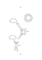
Фиг. 1 - принципиальная схема, демонстрирующая работу системы согласно настоящему изобретению, содержащей замаскированный телекоммуникационный элемент.FIG. 1 is a schematic diagram illustrating the operation of a system according to the present invention comprising a disguised telecommunications element.
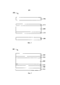
Фиг. 2 - вид в поперечном сечении многослойной оптической полимерной пленки согласно настоящему изобретению.FIG. 2 is a cross-sectional view of a multilayer optical polymer film according to the present invention.
Фиг. 3 - вид в поперечном сечении многослойной оптической полимерной пленки согласно другому воплощению настоящего изобретения.FIG. 3 is a cross-sectional view of a multilayer optical polymer film according to another embodiment of the present invention.
Фигуры не обязательно приведены в масштабе. Подобные ссылочные позиции на фигурах относятся к подобным компонентам. Однако следует понимать, что использование ссылочной позиции для указания компонента на определенной фигуре не обязывает обозначать компонент на другой фигуре той же ссылочной позицией.The figures are not necessarily to scale. Similar reference numerals in the figures relate to similar components. However, it should be understood that the use of a reference position to indicate a component in a certain figure does not oblige to designate a component in another figure with the same reference position.
Подробное описание изобретенияDETAILED DESCRIPTION OF THE INVENTION
В следующем подробном описании предпочтительных воплощений приводятся ссылки на сопроводительные чертежи, на которых показаны специфические воплощения, в которых настоящее изобретение может быть реализовано на практике. Показанные воплощения не охватывают все воплощения согласно настоящему изобретению. Следует понимать, что могут применяться и другие воплощения, при этом могут быть сделаны конструкционные или логические изменения без отклонения от объема настоящего изобретения. Таким образом, нижеследующее подробное описание не следует рассматривать в ограничительном смысле; объем настоящего изобретения определяется приложенной формулой изобретения.In the following detailed description of preferred embodiments, reference is made to the accompanying drawings, in which specific embodiments are shown in which the present invention may be practiced. The embodiments shown do not cover all embodiments according to the present invention. It should be understood that other embodiments may be used, and structural or logical changes may be made without departing from the scope of the present invention. Thus, the following detailed description should not be construed in a limiting sense; The scope of the present invention is defined by the appended claims.
Если не указано иное, все числа, обозначающие технологические размеры, количества и физические свойства, используемые в описании и формуле изобретения, должны рассматриваться как дополненные во всех случаях термином «приблизительно». Соответственно, если не указано обратное, числовые параметры, указанные в следующем описании и прилагаемой формуле изобретения, являются приблизительными значениями, которые могут изменяться в зависимости от предпочтительных свойств, которые стремятся получить специалисты в данной области техники с применением описанных в настоящем документе идей.Unless otherwise indicated, all numbers indicating the technological dimensions, quantities and physical properties used in the description and claims should be construed as supplemented in all cases by the term “approximately”. Accordingly, unless otherwise indicated, the numerical parameters indicated in the following description and the attached claims are approximate values that can vary depending on preferred properties that those skilled in the art seek to obtain using the ideas described herein.
Используемые в настоящем описании и прилагаемой формуле изобретения, формы единственного числа включают воплощения, имеющие ссылки на множественное число, если содержание ясно не указывает на обратное. Используемый в настоящем описании и прилагаемой формуле изобретения, термин «или» обычно применяется в том смысле, который включает значение «и/или», если содержание ясно не указывает на обратное.As used in the present description and the appended claims, the singular include embodiments with references to the plural, unless the content clearly indicates otherwise. Used in the present description and the attached claims, the term “or” is usually used in the sense that includes the meaning of “and / or”, unless the content clearly indicates otherwise.
Термины, относящиеся к пространственному расположению, включая, но не ограничиваясь следующими терминами - «вблизи», «дистальный», «нижний», «верхний», «под», «ниже», «над» и «сверху», если таковые используются в настоящем документе, применяются для простоты описания пространственных расположений элементов друг относительно друга. Такие относящиеся к пространственному расположению термины охватывают различные ориентации устройства при использовании или функционировании, в дополнение к частным вариантам ориентаций, показанным на фигурах и описанным в настоящем документе. Например, если изображенный на фигурах объект опрокинут или перевернут, тогда части ранее описанные, как находящиеся внизу или под другими элементами, теперь будут расположены над указанными другими элементами.Terms relating to spatial arrangement, including but not limited to the following terms - “near”, “distal”, “lower”, “upper”, “below”, “below”, “above” and “above”, if used are used herein for ease of describing spatial arrangements of elements with respect to each other. Such spatial-related terms encompass various orientations of the device when used or operated, in addition to the particular orientations shown in the figures and described herein. For example, if the object depicted in the figures is tilted or turned upside down, then the parts previously described as being below or below other elements will now be located above the indicated other elements.
В рамках настоящего документа, когда, например, элемент, компонент или слой описан, как формирующий «совпадающую границу раздела» с, или расположенный «на», «присоединенный к», «соединенный с», «уложенный на» или «контактирующий с» другим элементом, компонентом или слоем, он может быть расположен непосредственно на, присоединен непосредственно к, соединен непосредственно с, уложен непосредственно на, контактировать непосредственно с, или при этом промежуточные элементы, компоненты или слои могут быть расположены на, присоединены к, соединены с, или контактировать, например, с конкретным элементом, компонентом или слоем. Если элемент, компонент или слой, например, указан, как расположенный «непосредственно на», «присоединенный непосредственно к», «соединенный непосредственно с» или «контактирующий непосредственно с» другим элементом, то в таким случае не предполагается наличия, например, промежуточных элементов, компонентов или слоев.In the framework of this document, when, for example, an element, component or layer is described as forming a “matching interface” with, or located “on”, “attached to”, “connected to”, “laid on” or “in contact with” another element, component or layer, it can be located directly on, attached directly to, connected directly to, laid directly on, contact directly with, or intermediate elements, components or layers can be located on, attached to, connected Nena with, or contact, for example, with a particular element or component layer. If an element, component or layer, for example, is indicated as being located “directly on”, “connected directly to”, “connected directly to” or “contacting directly with” another element, then in this case, for example, there are no intermediate elements , components or layers.
Как указано выше, резкое увеличение количества абонентов беспроводной связи и соответствующего потока данных вызывает необходимость в установке узлов в виде макросот и малых сот, чтобы не отставать от требований к пропускной способности сети. Малая сота, установленные на крыше макроантенны и оборудование, а также другие обычно устанавливаемые телекоммуникационные элементы создают проблему, заключающуюся в том, что они потенциально менее эстетичны для проходящих мимо места установки. Таким образом, существует необходимость в обеспечении лучшей маскировки малых сот (и других типов оборудования для связи) от наблюдателей. В настоящем изобретении предлагается такое решение.As indicated above, a sharp increase in the number of wireless subscribers and the corresponding data stream necessitates the installation of nodes in the form of macrocells and small cells in order to keep up with the requirements for network bandwidth. The small cell, rooftop-mounted macro antennas and equipment, as well as other commonly installed telecommunications elements, pose the problem that they are potentially less aesthetic for those passing by. Thus, there is a need to provide better masking of small cells (and other types of communication equipment) from observers. The present invention provides such a solution.
На фундаментальном уровне в настоящем изобретении предлагается система, которая маскирует телекоммуникационные элементы от наблюдателей. В системе используется отражающий конструктивный элемент с высоким коэффициентом зеркального отражения (в частности многослойная оптическая полимерная пленка), который окружает телекоммуникационный элемент и скрывает его путем отражения естественного света и отражений окружающей систему обстановки в направлении наблюдателя, который смотрит на систему. Альтернативно, конструктивный элемент может иметь высокий показатель зеркальности и быть только частично отражающим, причем подложка за конструктивным элементом может поглощать любой пропускаемый свет (или лишь незначительно рассеивать его), причем такая подложка расположена между многослойной оптической пленкой и телекоммуникационным элементом. Схематическое изображение вышеуказанного представлено на фиг. 1, на которой показан отражающий конструктивный элемент 120 и наблюдатель 110, причем телекоммуникационный элемент скрыт конструктивным элементом 120. Скрытый телекоммуникационный элемент в некоторых воплощениях может представлять собой или содержать антенну, например, многодиапазонную направленную антенну Commscope, модель SBNH-1D6565B (Commscope, Inc., Хикори, Северная Каролина), или Kathrein, модель 840 10525 (Kathrein-Werke KG, Розенхайм, Германия). В некоторых воплощениях телекоммуникационный элемент может представлять собой элемент, который содержит как антенну, так и средство радиосвязи, например, средство радиосвязи со встроенной антенной Ericsson (Стокгольм, Швеция), модель AIR21 В1, или Alcatel Lucent, модель 9768 Metro Radio Outdoor (Alcatel Lucent, Булонь-Бийанкур, Франция). В другом воплощении элемент может представлять собой антенну малой соты, например, антенну Commscope, модель NH360QS-DG-F0M, или антенну Antenna Products, модель AWS360DP-1710-10-TO-D-A3 (Antenna Products Corp., Минерал Велс, Техас). В другом воплощении телекоммуникационный элемент может представлять собой антенну и средство радиосвязи, используемые для транспортной сети беспроводной связи, например, Ethernet-мост беспроводной связи на частоте 60 ГГц GE60 (BridgeWave, Санта-Клара, Калифорния).At a fundamental level, the present invention provides a system that masks telecommunication elements from observers. The system uses a reflective structural element with a high coefficient of specular reflection (in particular, a multilayer optical polymer film), which surrounds the telecommunication element and hides it by reflecting natural light and reflections of the environment surrounding the system in the direction of the observer who is looking at the system. Alternatively, the structural element can have a high specularity and be only partially reflective, and the substrate behind the structural element can absorb any transmitted light (or only slightly diffuse it), and such a substrate is located between the multilayer optical film and the telecommunication element. A schematic representation of the above is shown in FIG. 1, which shows a reflective
Описываемые в настоящем документе полимерные пленки используются снаружи помещений и подвергаются продолжительному воздействию, направленному на элементы. Следовательно, техническая задача при разработке и изготовлении неметаллизированных полимерных отражающих пленок заключается в обеспечении продолжительной (например, 20 лет) долговечности при воздействии жестких условий окружающей среды. Механические свойства, коэффициент зеркального отражения, стойкость к коррозии, устойчивость к ультрафиолетовому излучению, а также стойкость к внешним атмосферным условиям - это некоторые из факторов, которые могут способствовать постепенному ухудшению материалов в течение длительного периода работы.The polymer films described herein are used outdoors and are exposed to continuous exposure to the elements. Therefore, the technical problem in the development and manufacture of non-metallic polymer reflective films is to ensure long (for example, 20 years) durability when exposed to harsh environmental conditions. Mechanical properties, specular reflection coefficient, corrosion resistance, resistance to ultraviolet radiation, as well as resistance to external atmospheric conditions are some of the factors that can contribute to the gradual deterioration of materials over a long period of work.
Принципиальная схема многослойной оптической полимерной пленки 200, которая может быть использована в настоящем изобретении, представлена на фиг. 2. Первый элемент многослойной оптической полимерной пленки представляет собой центральный слой 202, который состоит из многослойной оптической стопы. Многослойная оптическая стопа центрального слоя 202 содержит два чередующихся полимерных слоя. Многослойная оптическая полимерная пленка опционально может также содержать защитный слой 204 (например, твердое покрытие или защитный ламинат), который расположен между наблюдателем и центральным слоем. Как будет более подробно описано ниже, защитный слой 204 может содержать один или более УФ-поглотителей, способствующих устойчивости многослойной оптической полимерной пленки к ухудшению свойств под действием УФ-излучения.A schematic diagram of a multilayer
Многослойная оптическая полимерная пленка 200 опционально также может содержать слой 208 адгезива, который расположен между центральным слоем 202 и поверхностью, на которую должна быть приклеена многослойная оптическая полимерная пленка (не показана). После приклеивания к такой поверхности многослойная оптическая полимерная пленка может принимать форму указанной поверхности. В ряде воплощений, чтобы способствовать маскировке многослойной оптической полимерной пленкой телекоммуникационного элемента, который она окружает, многослойной оптической полимерной пленке придана трехмерная форма. Может быть выбрана любая подходящая трехмерная форма, например, в одном воплощении многослойной оптической полимерной пленке может быть придана цилиндрическая форма. В другом воплощении многослойной оптической полимерной пленке может быть придана полусферическая форма. Используемое в настоящем документе выражение «придана форма» может означать, что самой пленке фактически придана указанная форма как самостоятельному элементу, или она нанесена на другую подложку или устройство, которое имеет желаемую форму (например, нанесена на полусферическую подложку), или на само устройство связи.The multilayer
Многослойная оптическая полимерная пленка 200 может дополнительно содержать первый наружный слой 212, выполненный из одного или более полимеров, который расположен между центральным слоем 202 и твердым покрытием 204. Первый наружный слой следует рассматривать как отдельный слой относительно центрального слоя. Дополнительно, оптическая полимерная пленка может содержать второй наружный слой 214, который содержит один или более полимеров, причем второй наружный слой расположен между центральным слоем 202 и слоем 208 адгезива (при его наличии). Второй наружный слой следует рассматривать как отдельный слой относительно центрального слоя. Дополнительно, по меньшей мере в одном воплощении, по меньшей мере один из полимеров в первом наружном слое не присутствует во втором наружном слое, и по меньшей мере один из полимеров во втором наружном слое не присутствует в первом наружном слое. Далее будет представлено более развернутое описание каждого из слоев многослойной оптической полимерной пленки.The multilayer
Защитный слойProtective layer
Защитный слой является опциональным. В определенных воплощениях для защиты многослойной оптической пленки подвергаемая воздействию поверхность пленки может быть защищена дополнительным слоем, который может быть нанесен в виде покрытия, совместно экструдирован, или наслоен на первый наружный слой. В одном воплощении первый наружный слой может быть покрыт стойким к механическим повреждениям и износу твердым покрытием. Защитный слой 204 может улучшать долговечность и стойкость к атмосферным воздействиям многослойной оптической пленки во время обработки и в течение использования конечного изделия. Слой твердого покрытия может содержать любой подходящий материал, например, акриловые твердые покрытия, твердые покрытия на основе окиси кремния, силоксановые твердые покрытия, меламиновые твердые покрытия и т.п. В случае акриловых твердых покрытий твердое покрытие может содержать один или более акриловых полимеров. Акриловые полимеры включают акрилаты, метакрилаты и их сополимеры. В одном воплощении твердое покрытие содержит более 90% (весовых процентов в пересчете на сухой вес) акриловых полимеров. В другом воплощении твердое покрытие содержит смесь 1,6-гександиол диакрилата (HDDA), который может быть доступен от Sartomer USA, LLC, и BASF Paraloid B44. В другом воплощении твердое покрытие содержит поли(метилметакрилатный) полимер или сополимер, по меньшей мере 80% акрилатного или диакрилатного мономера и стабилизатор ультрафиолетового излучения. Конечное покрытие получают путем светового отверждения состава твердого покрытия. Примеры таких композиций описаны в документе US 2015/0037567, включенном в настоящее описание посредством ссылки во всей полноте. В другом воплощении защитный слой может содержать пленку для защиты поверхности (например, защитный ламинат). Примеры включают без ограничения глянцевые защитные ламинаты 3М™ Scotchcal™ и пленку для защиты графических изображений и поверхности Scotchgard™.A protective layer is optional. In certain embodiments, to protect the multilayer optical film, the exposed film surface may be protected by an additional layer, which may be coated, coextruded, or laminated to the first outer layer. In one embodiment, the first outer layer may be coated with a hard coating resistant to mechanical damage and wear. The
Твердое покрытие может иметь любую подходящую толщину, например, такую как от 1 до 20 микрометров, или от 1 до 10 микрометров, или от 1 до 5 микрометров, или от 5 до 10 микрометров или от 8 до 12 микрометров. В одном воплощении толщина твердого покрытия составляет 9 микрометров. В другом воплощении толщина твердого покрытия составляет 10 микрометров.The hard coating can have any suitable thickness, for example, such as from 1 to 20 micrometers, or from 1 to 10 micrometers, or from 1 to 5 micrometers, or from 5 to 10 micrometers, or from 8 to 12 micrometers. In one embodiment, the thickness of the hard coating is 9 micrometers. In another embodiment, the thickness of the hard coating is 10 micrometers.
В одном воплощении слой твердого покрытия может содержать УФ-стабилизаторы (см. ниже), антиоксиданты, такие как TINUVIN 123, доступный от BASF Corporation, и сшивающие агенты и инициаторы сшивания, необходимые для обеспечения отверждения полимеров твердого покрытия, такие как, например, IRGACURE 184 и IRGACURE 819, также доступные от BASF Corporation. В одном воплощении твердое покрытие содержит от 1 до 7% УФ-стабилизаторов (весовых процентов в пересчете на сухой вес). В другом воплощении твердое покрытие содержит от 2 до 6% УФ-стабилизаторов (весовых процентов в пересчете на сухой вес). В других воплощениях твердое покрытие содержит 6% или менее, или 5% или менее, или 4% или менее, или 3% или менее УФ-стабилизаторов в весовых процентах в пересчете на сухой вес. В другом воплощении твердое покрытие может содержать стабилизатор, такой как Tinuvin CarboProtect, доступный от BASF, для защиты пленки от ухудшения свойств в УФ/видимой области (380-420 нм). Свойства твердого покрытия или любого другого защитного слоя не являются критичными для рабочих характеристик многослойной оптической пленки в качестве зеркальной пленки, при этом авторы изобретения предполагают, что известные прозрачные твердые покрытия или защитные слои могут быть использованы вблизи от первого наружного слоя многослойной оптической пленки. Специалистам в данной области техники будет понятно, что может быть использован слой грунтовочного покрытия или другая обработка поверхности для достижения надлежащей адгезии между защитным слоем и наружным слоем (наружными слоями).In one embodiment, the hard coating layer may contain UV stabilizers (see below), antioxidants such as TINUVIN 123, available from BASF Corporation, and crosslinking agents and crosslinking initiators necessary to provide curing of the hard coating polymers, such as, for example, IRGACURE 184 and IRGACURE 819, also available from BASF Corporation. In one embodiment, the solid coating comprises from 1 to 7% UV stabilizers (weight percent, calculated on dry weight). In another embodiment, the solid coating contains from 2 to 6% UV stabilizers (weight percent, calculated on dry weight). In other embodiments, the hard coating comprises 6% or less, or 5% or less, or 4% or less, or 3% or less UV stabilizers in weight percent based on dry weight. In another embodiment, the hard coating may contain a stabilizer, such as Tinuvin CarboProtect, available from BASF, to protect the film from deterioration in the UV / visible region (380-420 nm). The properties of the hard coating or any other protective layer are not critical to the performance of the multilayer optical film as a mirror film, and the inventors suggest that known transparent hard coatings or protective layers can be used close to the first outer layer of the multilayer optical film. Those skilled in the art will understand that a primer layer or other surface treatment can be used to achieve proper adhesion between the protective layer and the outer layer (outer layers).
Наружные слоиOuter layers
Наружный слой (например, 212, 214) может быть обеспечен посредством совместной экструзии на каждой из основных поверхностей многослойной стопы во время ее изготовления для придания желаемых свойств многослойной оптической стопе и для защиты ее от сдвига вдоль распределительного блока и стенок головки.An outer layer (e.g., 212, 214) can be provided by co-extrusion on each of the main surfaces of the multilayer stack during its manufacture to impart the desired properties to the multilayer optical stack and to protect it against shear along the distribution block and the head walls.
В некоторых воплощениях наружные слои 212, 214 могут содержать смесь из одного или более акрилатных полимеров и одного или более фторполимеров. Используемый в настоящем документе термин «акрилатные полимеры» включает акрилаты, метакрилаты и их сополимеры. Примеры таких полимеров включают полиакрилаты, полиметакрилаты, такие как поли(метилметакрилат) (РММА), либо в виде гомополимеров, либо в виде сополимеров, такие как соРММА, состоящий из 75 вес. % метилметакрилатных (ММА) мономеров и 25 вес. % этилакрилатных (ЕА) мономеров (доступных от Ineos Acrylics, Inc. под торговым наименованием Perspex СР63), соРММА, образованный из звеньев сомономера ММА и звеньев н-бутилметакрилатного (nBMA) сомономера.In some embodiments, the
В определенных воплощениях фторполимер, используемый в полимерной смеси наружного слоя, представляет собой материал, способный к экструзии. В некоторых воплощениях фторполимер может представлять собой частично фторированный полимер. Например, фторполимер может быть либо формируемым из расплава, например, как в случае поливинилиденфторида (PVDF), терполимера тетрафторэтилена, гексафторпропилена и винилиденфторида (THV), а также других формируемых из расплава фторопластов, либо может быть не формируемым из расплава, например, как в случае модифицированных сополимеров политетрафторэтилена (PTFE), таких как сополимер тетрафторэтилена с низкими уровнями фторированных простых виниловых эфиров и фторэластомеров. Фторэластомеры могут быть обработаны перед их отверждением посредством литья под давлением или прямого прессования, или других способов, обычно применяемых с термопластичными материалами. Фторэластомеры после отверждения или сшивания могут не иметь способности к дальнейшей обработке. Фторэластомеры также могут быть покрыты без применения растворителя в их несшитой форме. В одном воплощении фторполимер, смешанный с акриловым полимером, представляет собой PVDF.In certain embodiments, the fluoropolymer used in the polymer blend of the outer layer is an extrusion material. In some embodiments, the fluoropolymer may be a partially fluorinated polymer. For example, a fluoropolymer can be either melt-formed, for example, as in the case of polyvinylidene fluoride (PVDF), tetrafluoroethylene, hexafluoropropylene and vinylidene fluoride (THV) terpolymer, as well as other melt-formed fluoroplastics, or it may not be melt-formed, for example, as in in the case of modified polytetrafluoroethylene copolymers (PTFE), such as a copolymer of tetrafluoroethylene with low levels of fluorinated vinyl ethers and fluoroelastomers. Fluoroelastomers can be treated prior to curing by injection molding or direct compression, or other methods commonly used with thermoplastic materials. After curing or crosslinking, fluoroelastomers may not be capable of further processing. Fluoroelastomers can also be coated without the use of a solvent in their uncrosslinked form. In one embodiment, the fluoropolymer blended with an acrylic polymer is PVDF.
В других воплощениях фторполимер представляет собой фторопласт, содержащий сополимеризованные звенья, полученные из винилиденфторида (VDF) и фторэтилена, и может дополнительно содержать сополимеризованные звенья, полученные из других фторсодержащих мономеров, мономеров, не содержащих фтор, или их комбинации. Примеры подходящих фторсодержащих мономеров включают тетрафторэтилен (TFE), гексафторпропилен (HFP), хлотрифторэтилен (CTFE), 3-хлорпентафторпропен, перфторированные простые виниловые эфиры (например, простые виниловые эфиры перфторалкокси, такие как CF3OCF2CF2CF2OCF=CF2 и простые виниловые эфиры перфторалкила, такие как CF3OCF=CF2 и CF3CF2CF2OCF=CF2), винилфторид, и фторсодержащие диолефины, такие как перфтордиаллиловый эфир и перфтор-1,3-бутадиен. Примеры подходящих мономеров, не содержащих фтор, включают олефиновые мономеры, такие как этилен, пропилен и т.п.In other embodiments, the fluoropolymer is a fluoroplastic containing copolymerized units derived from vinylidene fluoride (VDF) and fluoroethylene, and may further comprise copolymerized units derived from other fluorine-containing monomers, fluorine-free monomers, or combinations thereof. Examples of suitable fluorinated monomers include tetrafluoroethylene (TFE), hexafluoropropylene (HFP), hlotriftoretilen (CTFE), 3-hlorpentaftorpropen, perfluorinated vinyl ethers (e.g., vinyl ethers perfluoroalkoxy, such as CF 3 OCF 2 CF 2 CF 2 OCF = CF 2 and perfluoroalkyl vinyl ethers such as CF 3 OCF = CF 2 and CF 3 CF 2 CF 2 OCF = CF 2 ), vinyl fluoride, and fluorine-containing diolefins such as perfluorodiallyl ether and perfluoro-1,3-butadiene. Examples of suitable fluorine-free monomers include olefin monomers such as ethylene, propylene and the like.
VDF-содержащие фторопласты могут быть получены при помощи методов эмульсионной полимеризации, описанных, например, в патенте US 4,338,237 (Sulzbach et al.) или патенте US 5,285,002 (Grootaert), включенных в настоящий документ посредством ссылки. Подходящие коммерчески доступные VDF-содержащие фторопласты включают, например, фторполимеры THV™ 200, THV ™ 400, THV ™ 5000, THV ™ 610Х (доступные от Dyneon LLC, Сент-Пол, Миннесота), фторполимер KYNAR™ 740 (доступный от Atochem North America, Филадельфия, Пенсильвания), HYLAR™ 700 (доступный от Ausimont USA, Inc., Морристаун, Нью-Джерси) и FLUOREL™ FC-2178 (доступный от Dyneon LLC).VDF-containing fluoroplastics can be obtained using the emulsion polymerization methods described, for example, in US patent 4,338,237 (Sulzbach et al.) Or US patent 5,285,002 (Grootaert), incorporated herein by reference. Suitable commercially available VDF-containing fluoroplastics include, for example,
Другие примеры фторполимеров включают THV™ (терполимер CF2=CF2/CF3CF=CF2/CF2=CH2), THE (терполимер CF2=CF2/CF3CF=CF2/CH2=CH2), PVDF-HV (сополимер CF2=CH2 (85 вес. %) и CF3CF=CF2 (15 вес. %)), и PVDF-CV (сополимер CF2=CH2 (85 вес. %), и CF2=CFCI (15 вес. %)).Other examples of fluoropolymers include THV ™ (terpolymer CF 2 = CF 2 / CF 3 CF = CF 2 / CF 2 = CH 2 ), THE (terpolymer CF 2 = CF 2 / CF 3 CF = CF 2 / CH 2 = CH 2 ) PVDF-HV (copolymer CF 2 = CH 2 (85 wt.%) And CF 3 CF = CF 2 (15 wt.%)), And PVDF-CV (copolymer CF 2 = CH 2 (85 wt.%), and CF 2 = CFCI (15 wt.%)).
В некоторых воплощениях наружный слой содержит от 50% до 70% одного или более акрилатных полимеров и от 25% до 40% одного или более фторполимеров в пересчете на сухой вес. В других воплощениях наружный слой содержит от 60% до 65% одного или более акрилатных полимеров и от 30% до 35% одного или более фторполимеров. В других воплощениях наружный слой содержит 63% одного или более акрилатных полимеров и 35% одного или более фторполимеров. В определенных воплощениях один или более акрилатных полимеров представляют собой РММА и один или более фторполимеров представляют собой PVDF.In some embodiments, the outer layer comprises from 50% to 70% of one or more acrylate polymers and from 25% to 40% of one or more fluoropolymers, calculated on dry weight. In other embodiments, the outer layer comprises from 60% to 65% of one or more acrylate polymers and from 30% to 35% of one or more fluoropolymers. In other embodiments, the outer layer comprises 63% of one or more acrylate polymers and 35% of one or more fluoropolymers. In certain embodiments, one or more acrylate polymers are PMMA and one or more fluoropolymers are PVDF.
В некоторых воплощениях наружный слой содержит добавки, такие как, например, один или более УФ-стабилизаторов. В некоторых воплощениях наружный слой содержит от 0 до 5% УФ-стабилизатора. В некоторых воплощениях наружный слой содержит 1%, или 2%, или 3%, или 4%, или 5% УФ-стабилизатора. В других воплощениях УФ стабилизатор представляет собой Tin-1600.In some embodiments, the outer layer contains additives, such as, for example, one or more UV stabilizers. In some embodiments, the outer layer contains from 0 to 5% UV stabilizer. In some embodiments, the outer layer contains 1%, or 2%, or 3%, or 4%, or 5% of a UV stabilizer. In other embodiments, the UV stabilizer is a Tin-1600.
В определенных воплощениях первый или второй наружный слой содержит один или более сложных полиэфиров. В одном воплощении сложные полиэфиры включают кристаллические или полукристаллические сложные полиэфиры, сложные сополиэфиры и модифицированные сложные сополиэфиры. В контексте настоящего документа термин «сложный полиэфир» включает гомополимеры и сополимеры. Сложные полиэфиры, подходящие для использования, в целом включают карбоксилатные и гликолевые части звеньев и могут быть образованы в результате реакций молекул карбоксилатного мономера с молекулами гликолевого мономера. Каждая молекула карбоксилатного мономера содержит две или более функциональных групп карбоновой кислоты или функциональных сложноэфирных групп, и каждая молекула гликолевого мономера содержит две или более функциональных гидроксигрупп. Все молекулы карбоксилатного мономера могут быть одинаковыми или могут представлять собой два или более различных типов молекул. То же применимо к молекулам гликолевого мономера. Под термином «сложный полиэфир» также следует понимать поликарбонаты, полученные в результате реакции молекул гликолевого мономера со сложными эфирами угольной кислоты.In certain embodiments, the first or second outer layer comprises one or more polyesters. In one embodiment, the polyesters include crystalline or semi-crystalline polyesters, copolyesters and modified copolyesters. As used herein, the term “polyester” includes homopolymers and copolymers. Suitable polyesters for use generally include the carboxylate and glycol moieties of the units and can be formed by reactions of carboxylate monomer molecules with glycol monomer molecules. Each carboxylate monomer molecule contains two or more functional carboxylic acid groups or functional ester groups, and each glycol monomer molecule contains two or more hydroxy functional groups. All carboxylate monomer molecules may be the same or may be two or more different types of molecules. The same applies to glycol monomer molecules. The term "polyester" should also be understood as polycarbonates obtained by the reaction of glycol monomer molecules with carbonic esters.
Молекулы карбоксилатного мономера, подходящие для использования при образовании карбоксилатных частей звеньев сложного полиэфира включают, например, терефталевую кислоту; изофталевую кислоту; 2,6-нафталиндикарбоновую кислоту и ее изомеры; фталевую кислоту; азелаиновую кислоту; адипиновую кислоту; себациновую кислоту; норборнен-дикарбоновую кислоту; бициклооктан-дикарбоновую кислоту; 1,4-циклогексан-дикарбоновую кислоту и ее изомеры; трет-бутил-изофталевую кислоту, тримеллитовую кислоту, натриевую соль сульфоизофталевой кислоты; 4,4'-бифенил-дикарбоновую кислоту и ее изомеры; и сложные эфиры низших алкилов этих кислот, такие как сложные метиловые или этиловые эфиры. Термин «низший алкил» в данном контексте относится к C1-С10алкильным группам с прямой или разветвленной цепью.Carboxylate monomer molecules suitable for use in forming the carboxylate moieties of polyester units include, for example, terephthalic acid; isophthalic acid; 2,6-naphthalenedicarboxylic acid and its isomers; phthalic acid; azelaic acid; adipic acid; sebacic acid; norbornene-dicarboxylic acid; bicyclooctane dicarboxylic acid; 1,4-cyclohexane-dicarboxylic acid and its isomers; tert-butyl-isophthalic acid, trimellitic acid, sodium salt of sulfoisophthalic acid; 4,4'-biphenyl-dicarboxylic acid and its isomers; and lower alkyl esters of these acids, such as methyl or ethyl esters. The term “lower alkyl” as used herein refers to straight or branched chain C 1 -C 10 alkyl groups.
Молекулы гликолевого мономера, подходящие для использования при образовании гликолевых частей звеньев сложного полиэфира включают этиленгликоль; пропиленгликоль; 1,4-бутандиол и его изомеры; 1,6-гександиол; неопентилгликоль; полиэтиленгликоль; диэтиленгликоль; трициклодекандиол; 1,4-циклогександиметанол и его изомеры; норборнандиол; бицикло-октандиол; триметилолпропан; пентаэритрит; 1,4-бензолдиметанол и его изомеры; бисфенол А; 1,8-дигидроксибифенил и его изомеры; и 1,3-бис-(2-гидроксизтокси)-бензол.Glycol monomer molecules suitable for use in forming the glycol moieties of the polyester units include ethylene glycol; propylene glycol; 1,4-butanediol and its isomers; 1,6-hexanediol; neopentyl glycol; polyethylene glycol; diethylene glycol; tricyclodecandiol; 1,4-cyclohexanedimethanol and its isomers; norbornanediol; bicyclo-octanediol; trimethylolpropane; pentaerythritol; 1,4-benzenedimethanol and its isomers; bisphenol A; 1,8-dihydroxybiphenyl and its isomers; and 1,3-bis- (2-hydroxy istoxy) benzene.
Приведенный в качестве примера полимер, используемый в качестве двулучепреломляющего слоя в многослойных оптических стопах согласно настоящему изобретению, представляет собой полиэтилентерефталат (PET). Другой используемый двулучепреломляющий полимер представляет собой полиэтиленнафталат (PEN). В одном воплощении один или более сложных полиэфиров второго наружного слоя образованы из 100% PET.An exemplary polymer used as a birefringent layer in multilayer optical stacks according to the present invention is polyethylene terephthalate (PET). Another birefringent polymer used is polyethylene naphthalate (PEN). In one embodiment, one or more polyesters of the second outer layer are formed from 100% PET.
В некоторых воплощениях каждый из наружных слоев имеет толщину от 6 микрометров до 12 микрометров. В некоторых воплощениях каждый из наружных слоев имеет толщину 9 микрометров. В некоторых воплощениях каждый из наружных слоев имеет толщину по меньшей мере 10 микрометров, по меньшей мере 50 микрометров или по меньшей мере 60 микрометров. Кроме того, в некоторых воплощениях каждый из наружных слоев имеет толщину не более 200 микрометров, не более 150 микрометров или не более 100 микрометров. В некоторых воплощениях каждый из наружных слоев имеет толщину не более 5 микрометров.In some embodiments, each of the outer layers has a thickness of from 6 micrometers to 12 micrometers. In some embodiments, each of the outer layers has a thickness of 9 micrometers. In some embodiments, each of the outer layers has a thickness of at least 10 micrometers, at least 50 micrometers, or at least 60 micrometers. In addition, in some embodiments, each of the outer layers has a thickness of not more than 200 micrometers, not more than 150 micrometers, or not more than 100 micrometers. In some embodiments, each of the outer layers has a thickness of not more than 5 micrometers.
Многослойная оптическая стопа (центральный слой)Multilayer optical foot (center layer)
В одном воплощении многослойная оптическая стопа содержит чередующиеся слои по меньшей мере одного двулучепреломляющего полимера и одного второго полимера. Многослойные оптические стопы по существу представляют собой множество чередующихся полимерных слоев, которые могут быть выбраны для достижения отражения конкретной ширины спектра электромагнитного излучения.In one embodiment, the multilayer optical stack comprises alternating layers of at least one birefringent polymer and one second polymer. Multilayer optical stacks are essentially a plurality of alternating polymer layers that can be selected to achieve reflection of a particular width of the spectrum of electromagnetic radiation.
Материалы, подходящие для изготовления по меньшей мере одного двулучепреломляющего слоя многослойной оптической стопы согласно настоящему изобретению, включают кристаллические, полукристаллические или жидкокристаллические полимеры (например, сложные полиэфиры, сложные сополиэфиры и модифицированные сложные сополиэфиры). В данном контексте следует понимать, что термин «полимер» включает гомополимеры, сополимеры (например, полимеры, образованные при помощи двух или более различных мономеров), олигомеры и их комбинации, а также полимеры, олигомеры или сополимеры, которые могут быть образованы в виде смешиваемой смеси, например, путем совместной экструзии или в результате реакции, включая межмолекулярную переэтерификацию. Термины «полимер» и «сополимер» включают как статистические, так и блок-сополимеры.Materials suitable for the manufacture of at least one birefringent layer of a multilayer optical foot according to the present invention include crystalline, semi-crystalline or liquid crystalline polymers (e.g., polyesters, copolyesters and modified copolyesters). In this context, it should be understood that the term "polymer" includes homopolymers, copolymers (for example, polymers formed using two or more different monomers), oligomers and combinations thereof, as well as polymers, oligomers or copolymers that can be formed as miscible mixtures, for example, by co-extrusion or by reaction, including intermolecular transesterification. The terms “polymer” and “copolymer” include both random and block copolymers.
Сложные полиэфиры, подходящие для использования в некоторых приведенных в качестве примера многослойных оптических стопах, выполненных согласно настоящему изобретению, в целом включают карбоксилатные и гликолевые части звеньев и могут быть образованы в результате реакций молекул карбоксилатного мономера с молекулами гликолевого мономера. Каждая молекула карбоксилатного мономера содержит две или более функциональных групп карбоновой кислоты или функциональных сложноэфирных групп, и каждая молекула гликолевого мономера содержит две или более функциональных гидроксигрупп. Все молекулы карбоксилатного мономера могут быть одинаковыми или могут представлять собой два или более различных типов молекул. То же применимо к молекулам гликолевого мономера. Под термином «сложный полиэфир» также следует понимать поликарбонаты, полученные в результате реакции молекул гликолевого мономера со сложными эфирами угольной кислоты.Polyesters suitable for use in some exemplary multilayer optical feet made according to the present invention generally include carboxylate and glycol moieties and can be formed by reactions of carboxylate monomer molecules with glycol monomer molecules. Each carboxylate monomer molecule contains two or more functional carboxylic acid groups or functional ester groups, and each glycol monomer molecule contains two or more hydroxy functional groups. All carboxylate monomer molecules may be the same or may be two or more different types of molecules. The same applies to glycol monomer molecules. The term "polyester" should also be understood as polycarbonates obtained by the reaction of glycol monomer molecules with carbonic esters.
Молекулы карбоксилатного мономера, подходящие для использования при образовании карбоксилатных частей звеньев слоев сложного полиэфира включают, например, 2,6-нафталиндикарбоновую кислоту и ее изомеры; терефталевую кислоту; изофталевую кислоту; фталевую кислоту; азелаиновую кислоту; адипиновую кислоту; себациновую кислоту; норборнен-дикарбоновую кислоту; бициклооктан-дикарбоновую кислоту; 1,4-циклогексан-дикарбоновую кислоту и ее изомеры; трет-бутил-изофталевую кислоту, тримеллитовую кислоту, натриевую соль сульфоизофталевой кислоты; 4,4'-бифенил-дикарбоновую кислоту и ее изомеры; и сложные эфиры низших алкилов этих кислот, такие как сложные метиловые или этиловые эфиры. Термин «низший алкил» в данном контексте относится к C1-С10алкильным группам с прямой или разветвленной цепью.Carboxylate monomer molecules suitable for use in forming the carboxylate moieties of the polyester layer units include, for example, 2,6-naphthalenedicarboxylic acid and its isomers; terephthalic acid; isophthalic acid; phthalic acid; azelaic acid; adipic acid; sebacic acid; norbornene-dicarboxylic acid; bicyclooctane dicarboxylic acid; 1,4-cyclohexane-dicarboxylic acid and its isomers; tert-butyl-isophthalic acid, trimellitic acid, sodium salt of sulfoisophthalic acid; 4,4'-biphenyl-dicarboxylic acid and its isomers; and lower alkyl esters of these acids, such as methyl or ethyl esters. The term “lower alkyl” as used herein refers to straight or branched chain C 1 -C 10 alkyl groups.
Молекулы гликолевого мономера, подходящие для использования при образовании гликолевых частей звеньев слоев сложного полиэфира включают этиленгликоль; пропиленгликоль; 1,4-бутандиол и его изомеры; 1,6-гександиол; неопентилгликоль; полиэтиленгликоль; диэтиленгликоль; трициклодекандиол; 1,4-циклогександиметанол и его изомеры; норборнандиол; бицикло-октандиол; триметилолпропан; пентаэритрит; 1,4-бензолдиметанол и его изомеры; бисфенол А; 1,8-дигидроксибифенил и его изомеры; и 1,3-бис-(2-гидроксиэтокси)-бензол.Glycol monomer molecules suitable for use in forming the glycol moieties of the polyester layer units include ethylene glycol; propylene glycol; 1,4-butanediol and its isomers; 1,6-hexanediol; neopentyl glycol; polyethylene glycol; diethylene glycol; tricyclodecandiol; 1,4-cyclohexanedimethanol and its isomers; norbornanediol; bicyclo-octanediol; trimethylolpropane; pentaerythritol; 1,4-benzenedimethanol and its isomers; bisphenol A; 1,8-dihydroxybiphenyl and its isomers; and 1,3-bis- (2-hydroxyethoxy) benzene.
Приведенный в качестве примера полимер, используемый в качестве двулучепреломляющего слоя в многослойных оптических стопах согласно настоящему изобретению, представляет собой полиэтилентерефталат (PET). Другой используемый двулучепреломляющий полимер представляет собой полиэтиленнафталат (PEN). Молекулярная ориентация двулучепреломляющего полимера может быть увеличена путем растягивания материала до больших степеней растяжения и выдерживания неизменными других условий растяжения. Сополимеры PEN (coPEN), например, описанные в патенте US 6,352,761 и патенте US 6,449,093, используются в связи с их способностью к обработке при низкой температуре, что делает их более совместимыми в отношении совместной экструзии с менее термоустойчивыми вторыми полимерами. Другие полукристаллические сложные полиэфиры, подходящие для использования в качестве двулучепреломляющих полимеров, включают, например, полибутилен-2,6-нафталат (PBN) и его сополимеры, а также сополимеры полиэтилентерефталата (PET), например, описанные в патенте US 6,449,093 В2 или публикации патента US 2006/0084780, которые включены в настоящий документ посредством ссылки на их описание двулучепреломляющих полимеров и сложных полиэфиров. В качестве альтернативы другим используемым двулучепреломляющим полимером является синдиотактический полистирол (sPS).An exemplary polymer used as a birefringent layer in multilayer optical stacks according to the present invention is polyethylene terephthalate (PET). Another birefringent polymer used is polyethylene naphthalate (PEN). The molecular orientation of the birefringent polymer can be increased by stretching the material to high degrees of stretching and keeping other tensile conditions unchanged. PEN copolymers (coPEN), for example those described in US Pat. No. 6,352,761 and US Pat. No. 6,449,093, are used due to their low temperature processing ability, which makes them more compatible with respect to coextrusion with less heat-resistant second polymers. Other semi-crystalline polyesters suitable for use as birefringent polymers include, for example, polybutylene-2,6-naphthalate (PBN) and its copolymers, as well as copolymers of polyethylene terephthalate (PET), for example, as described in US patent 6,449,093 B2 or patent publication US 2006/0084780, which are incorporated herein by reference to their description of birefringent polymers and polyesters. As an alternative, the other birefringent polymer used is syndiotactic polystyrene (sPS).
Второй полимер многослойной оптической стопы может выбран из ряда полимеров, имеющих температуры стеклования, совместимые с таковыми первого двулучепреломляющего полимера, а также имеющие показатели преломления, аналогичные показателю анизотропного преломления (вне плоскости или nz) двулучепреломляющего полимера.The second polymer of the multilayer optical stack can be selected from a number of polymers having glass transition temperatures compatible with those of the first birefringent polymer, and also having refractive indices similar to the anisotropic refractive index (off-plane or n z ) of the birefringent polymer.
Примеры других полимеров, подходящих для использования в оптических стопах в качестве второго полимера, включают виниловые полимеры и сополимеры, состоящие из мономеров, такие как винилнафталины, стирол, малеиновый ангидрид, акрилаты и метакрилаты. Примеры таких полимеров включают полиакрилаты, полиметакрилаты, такие как поли(метилметакрилат) (РММА) и изотактический или синдиотактический полистирол. Другие полимеры включают конденсационные полимеры, такие как полисульфоны, полиамиды, полиуретаны, полиамидокислоты и полиимиды. Кроме того, второй полимер может быть образован из гомополимеров и сополимеров сложных полиэфиров, поликарбонатов, фторполимеров и полидиметилсилоксанов, а также их смесей.Examples of other polymers suitable for use in optical feet as a second polymer include vinyl polymers and monomer copolymers such as vinyl naphthalenes, styrene, maleic anhydride, acrylates and methacrylates. Examples of such polymers include polyacrylates, polymethacrylates such as poly (methyl methacrylate) (PMMA) and isotactic or syndiotactic polystyrene. Other polymers include condensation polymers such as polysulfones, polyamides, polyurethanes, polyamic acids and polyimides. In addition, the second polymer can be formed from homopolymers and copolymers of polyesters, polycarbonates, fluoropolymers and polydimethylsiloxanes, as well as mixtures thereof.
Например, в одном аспекте первый полимерный слой содержит двулучепреломляющий материал, а второй полимерный слой содержит полимер на основе акрила, смешанный со фторполимером, или акрилсодержащий сополимер. Данная конструкция может обеспечивать центральный слой с разницей показателей преломления между первым и вторым слоями, составляющей приблизительно 0,19. Например, первый слой может содержать PET, который имеет показатель преломления приблизительно 1,57, причем показатель преломления в продольном и поперечном направлениях составляет приблизительно 1,65 и показатель анизотропии (nz) составляет приблизительно 1,49. Второй полимерный слой может содержать полимер на основе акрила, такой как РММА, имеющий показатель преломления приблизительно 1,49, который смешан с фторполимером, таким как PVDF, имеющим показателем преломления приблизительно 1,42, в результате чего показатель преломления смеси составляет приблизительно 1,46. В результате значения отражения многослойной оптической стопы могут быть очень высокими.For example, in one aspect, the first polymer layer comprises a birefringent material, and the second polymer layer comprises an acrylic-based polymer mixed with a fluoropolymer, or an acrylic-containing copolymer. This design can provide a center layer with a difference in refractive index between the first and second layers of approximately 0.19. For example, the first layer may comprise a PET that has a refractive index of approximately 1.57, with a longitudinal and transverse refractive index of approximately 1.65 and an anisotropy index (n z ) of approximately 1.49. The second polymer layer may comprise an acrylic-based polymer such as PMMA having a refractive index of approximately 1.49, which is mixed with a fluoropolymer such as PVDF having a refractive index of approximately 1.42, resulting in a refractive index of the mixture of approximately 1.46 . As a result, the reflection values of the multilayer optical foot can be very high.
Другие приведенные в качестве примера полимеры, подходящие для использования в качестве второго полимера, включают гомополимеры РММА, например, доступные от Ineos Acrylics, Inc., Уилмингтон, Дэлавер, под торговыми наименованиями СР71 и СР80, или полиэтилметакрилат (РЕМА), который имеет более низкую температуру стеклования, чем РММА. Дополнительные вторые полимеры включают сополимеры РММА (соРММА), такие как соРММА, состоящие из 75 вес. % метилметакрилатных (ММА) мономеров и 25 вес. % этилакрилатных (ЕА) мономеров, (доступные от Ineos Acrylics, Inc., под торговым наименованием Perspex СР63), соРММА, образованный из звеньев сомономера ММА и звеньев н-бутилметакрилатного (nBMA) сомономера, или смесь РММА и поли(винилиденфторида) (PVDF).Other exemplary polymers suitable for use as the second polymer include PMMA homopolymers, for example, available from Ineos Acrylics, Inc., Wilmington, Delaware, under the trade names CP71 and CP80, or polyethylene methacrylate (PEMA), which has a lower glass transition temperature than PMMA. Additional second polymers include copolymers of PMMA (coMPA), such as coMPMA, consisting of 75 weight. % methyl methacrylate (MMA) monomers and 25 weight. % ethyl acrylate (EA) monomers, (available from Ineos Acrylics, Inc., under the trade name Perspex CP63), coMPMA formed from MMA comonomer units and n-butyl methacrylate (nBMA) comonomer units, or a mixture of PMMA and poly (vinylidene fluoride) (PVD) )
Еще одни подходящие полимеры, используемые в качестве второго полимера, включают полиолефиновые сополимеры, такие как сополимер этилена и октена (РЕ-РО), доступный от Dupont Performance Elastomers под торговым наименованием Engage 8200, сополимер пропилена и этилена (РРРЕ), доступный от Fina Oil и Chemical Co., Даллас, Техас, под торговым наименованием Z9470, и сополимер атактического полипропилена (аРР) и изотактического полипропилена (iPP). Многослойные оптические стопы также могут содержать, например, во вторых полимерных слоях, функционализированный полиолефин, такой как линейный полиэтилен низкой плотности, привитый малеиновым ангидридом (LLDPE-g-MA), например, доступный от E.I. duPont de Nemours & Co., Inc., Уилмингтон, Дэлавер, под торговым наименованием Bynel 4105.Still other suitable polymers used as the second polymer include polyolefin copolymers such as ethylene-octene copolymer (PE-PO), available from Dupont Performance Elastomers under the trade name Engage 8200, propylene-ethylene copolymer (PPPE), available from Fina Oil and Chemical Co., Dallas, Texas, under the trade name Z9470, and a copolymer of atactic polypropylene (aPP) and isotactic polypropylene (iPP). Multilayer optical stacks may also contain, for example, in the second polymer layers, a functionalized polyolefin, such as linear low density polyethylene grafted with maleic anhydride (LLDPE-g-MA), for example, available from E.I. duPont de Nemours & Co., Inc., Wilmington, Delaware, under the trade name Bynel 4105.
В одном воплощении композиции полимера, подходящие в качестве второго полимера в чередующихся слоях по меньшей мере с одним двулучепреломляющим полимером, включают РММА, соРММА, сегментированный сополимер полидиметилсилоксана и оксамида (SPOX), фторполимеры, содержащие гомополимеры, такие как PVDF, и сополимеры, например, полученные из тетрафторэтилена, гексафторпропилена и винилиденфторида (THV), смеси PVDF/PMMA, акрилатные сополимеры, стирол, стироловые сополимеры, силиконовые сополимеры, поликарбонат, поликарбонатные сополимеры, поликарбонатные смеси, смеси поликарбоната и стирол-малеинового ангидрида, и сополимеры циклического олефина.In one embodiment, polymer compositions suitable as a second polymer in alternating layers with at least one birefringent polymer include PMMA, coMPMA, segmented polydimethylsiloxane-oxamide copolymer (SPOX), fluoropolymers containing homopolymers such as PVDF, and copolymers, for example obtained from tetrafluoroethylene, hexafluoropropylene and vinylidene fluoride (THV), PVDF / PMMA mixtures, acrylate copolymers, styrene, styrene copolymers, silicone copolymers, polycarbonate, polycarbonate copolymers, polycarbonate mixtures, mixtures of polycarbonate and styrene-maleic anhydride, and cyclic olefin copolymers.
На выбор композиций полимера, используемых при создании многослойной оптической стопы, может влиять необходимость в отражении заданной ширины спектра поступающего излучения. Более высокие различия в показателях преломления между двулучепреломляющим полимером и вторым полимером вызывают появление большей оптической мощности, таким образом, обеспечивая большую ширину спектра отражения. Альтернативно, могут использоваться дополнительные слои для обеспечения большей оптической мощности. Примеры комбинаций двулучепреломляющих слоев и вторых полимерных слоев могут включать, например, следующее: РЕТ/соРММА, PETYTHV, PET/SPOX, PEN/THV, PEN/SPOX, PEN/PMMA, PEN/coPMMA, coPEN/PMMA, coPEN/SPOX, sPS/SPOX, sPS/THV, CoPEN/THV, РЕТ/фторэластомеры, sPS/фторэластомеры и coPEN/фторэластомеры.The choice of polymer compositions used to create a multilayer optical stack may be affected by the need to reflect a given spectrum width of the incoming radiation. Higher differences in refractive indices between the birefringent polymer and the second polymer give rise to greater optical power, thereby providing a wider reflection spectrum. Alternatively, additional layers may be used to provide greater optical power. Examples of combinations of birefringent layers and second polymer layers may include, for example, the following: PET / coMPMA, PETYTHV, PET / SPOX, PEN / THV, PEN / SPOX, PEN / PMMA, PEN / coPMMA, coPEN / PMMA, coPEN / SPOX, sPS / SPOX, sPS / THV, CoPEN / THV, PET / fluoroelastomers, sPS / fluoroelastomers and coPEN / fluoroelastomers.
Приведенные в качестве примера многослойные оптические стопы согласно настоящему изобретению могут быть получены, например, при помощи устройства и способов, описанных в патенте US 6,783,349 под названием «Apparatus for Making Multilayer Optical Films», патенте US 6,827,886 под названием «Method for Making Multilayer Optical Films», публикациях PCT WO 2009/140493 под названием «Solar Concentrating Mirror» и WO 2011/062836 под названием «Multi-layer Optical Films», все из которых включены в настоящий документ посредством ссылки во всей полноте. Примеры дополнительных слоев или покрытий, подходящих для использования с приведенными в качестве примера многослойными оптическими стопами согласно настоящему изобретению описаны, например, в патентах US 6,368,699 и 6,459,514, оба из которых озаглавлены «Multilayer Polymer Film with Additional Coatings or Layers» и включены в настоящий документ посредством ссылки во всей полноте.Exemplary multilayer optical stacks according to the present invention can be obtained, for example, using the device and methods described in US Pat. No. 6,783,349, entitled "Apparatus for Making Multilayer Optical Films", US Pat. No. 6,827,886, called "Method for Making Multilayer Optical Films ", PCT Publications WO 2009/140493 entitled" Solar Concentrating Mirror "and WO 2011/062836 under the name" Multi-layer Optical Films ", all of which are incorporated herein by reference in their entirety. Examples of additional layers or coatings suitable for use with the exemplary multilayer optical feet of the present invention are described, for example, in US Pat. Nos. 6,368,699 and 6,459,514, both of which are entitled “Multilayer Polymer Film with Additional Coatings or Layers” and are incorporated herein. by reference in its entirety.
В некоторых воплощениях многослойная оптическая стопа может иметь спектральные участки с высоким коэффициентом отражения (>90%) и другие спектральные участки с высоким коэффициентом пропускания (>90%). В некоторых воплощениях многослойная оптическая стопа имеет высокий коэффициент отражения в оптической области относительно части спектра солнечного излучения, низкий коэффициент диффузного отражения, низкий показатель пожелтения, удовлетворительную стойкость к атмосферным воздействиям, удовлетворительную стойкость к истиранию, механическим повреждениям и растрескиванию во время обращения и очистки, и удовлетворительную адгезию к другим слоям, например, другим (со)полимерным слоям, нанесенным на одну или обе основные поверхности пленок, при их использовании в качестве подложек.In some embodiments, the multilayer optical stack may have spectral regions with a high reflectance (> 90%) and other spectral regions with a high transmittance (> 90%). In some embodiments, the multilayer optical stack has a high reflectance in the optical region relative to part of the solar radiation spectrum, a low diffuse reflectance, a low yellowing index, satisfactory resistance to weathering, satisfactory abrasion, mechanical damage and cracking during handling and cleaning, and satisfactory adhesion to other layers, for example, other (co) polymer layers deposited on one or both main surfaces flax, when they are used as substrates.
В других воплощениях средний коэффициент отражения вдоль каждого направления растягивания при нормальном падении в области длин волн 380-1500 нм составляет более 90 процентов, или более 95 процентов, или более 98 процентов, или более 99 процентов.In other embodiments, the average reflection coefficient along each direction of stretching with a normal incidence in the wavelength range of 380-1500 nm is more than 90 percent, or more than 95 percent, or more than 98 percent, or more than 99 percent.
В некоторых альтернативных воплощениях средний коэффициент отражения вдоль каждого направления растягивания при нормальном падении в диапазоне длин волн 380-1500 нм может быть меньше, чем значения отражения в воплощениях, описанных непосредственно выше, но по-прежнему более 50 процентов или более 60 процентов. В этих альтернативных воплощениях надлежащая темноокрашенная подложка (потенциально поглощающая свет или слегка рассеивающая) может быть расположена между пленкой и маскируемым объектом. Приведенная в качестве примера темноокрашенная подложка может содержать пленку 3М 1080-М12 (доступную от 3М Company).In some alternative embodiments, the average reflection coefficient along each direction of stretching at a normal incidence in the wavelength range of 380-1500 nm may be less than the reflection values in the embodiments described immediately above, but still more than 50 percent or more than 60 percent. In these alternative embodiments, a suitable dark-colored substrate (potentially light absorbing or slightly scattering) may be located between the film and the masked object. An exemplary dark-colored substrate may comprise a 3M 1080-M12 film (available from 3M Company).
Например, на фиг. 3 показана многослойная оптическая полимерная пленка 300, которая содержит темноокрашенную подложку 315. Аналогично вышеописанному относительно фиг. 2, первый элемент многослойной оптической полимерной пленки содержит центральный слой 302, который состоит из многослойной оптической стопы. Многослойная оптическая стопа центрального слоя 302 содержит два чередующихся полимерных слоя. Многослойная оптическая полимерная пленка 300 опционально может также содержать защитный слой 304 (например, твердое покрытие или защитный ламинат), который расположен между наблюдателем и центральным слоем. Защитный слой 304 может содержать один или более УФ-поглотителей, способствующих устойчивости многослойной оптической полимерной пленки к ухудшению свойств под действием УФ-излучения.For example, in FIG. 3 shows a multilayer
Многослойная оптическая полимерная пленка 300 также может содержать слой 308 адгезива, который расположен между центральным слоем 302 и темноокрашенной подложкой 315, содержащей поверхность, на которую должна быть приклеена многослойная оптическая полимерная пленка. После приклеивания к такой поверхности многослойная оптическая полимерная пленка может принимать форму подложки 315.The multilayer
Многослойная оптическая полимерная пленка 300 может дополнительно содержать первый наружный слой 312, выполненный из одного или более полимеров, который расположен между центральным слоем 302 и твердым покрытием 304. Первый наружный слой можно рассматривать как отдельный слой относительно центрального слоя. Кроме того, оптическая полимерная пленка может содержать второй наружный слой 314, который содержит один или более полимеров, причем второй наружный слой расположен между центральным слоем 302 и слоем 308 адгезива (при его наличии).The multilayer
В других воплощениях средний коэффициент отражения под углом 60 градусов относительно нормали в диапазоне 380-750 нм составляет более 80 процентов, более 90 процентов, более 95 процентов, более 98 процентов или более 99 процентов. Пленка, которая поддерживает высокий коэффициент отражения в широком диапазоне углов падения и поляризации, создает отраженные изображения, которые могут эффективно маскировать предполагаемое для использования оборудование для связи.In other embodiments, the average reflection coefficient at an angle of 60 degrees relative to the normal in the range of 380-750 nm is more than 80 percent, more than 90 percent, more than 95 percent, more than 98 percent or more than 99 percent. A film that maintains a high reflectance over a wide range of incidence and polarization angles creates reflected images that can effectively mask the communications equipment intended for use.
В альтернативных воплощениях средний коэффициент отражения под углом 60 градусов относительно нормали в диапазоне 380-750 нм может представлять собой более низкое значение, чем в воплощениях, описанных непосредственно выше, но по-прежнему составлять более 50 процентов или более 60 процентов. Например, надлежащая темноокрашенная подложка (потенциально поглощающая свет или слегка рассеивающая) может быть расположена между пленкой и маскируемым объектом. В тех воплощениях, в которых коэффициент отражения более низкий (например, 50%, или 60% или 70%), пленка может быть размещена поверх темного фона, чтобы добиться максимальной маскировки за счет зеркального отражения.In alternative embodiments, the average reflection coefficient at an angle of 60 degrees relative to the normal in the range of 380-750 nm may be a lower value than in the embodiments described immediately above, but still be more than 50 percent or more than 60 percent. For example, a suitable dark-colored substrate (potentially light absorbing or slightly scattering) may be located between the film and the masked object. In those embodiments in which the reflection coefficient is lower (for example, 50%, or 60% or 70%), the film can be placed over a dark background to achieve maximum masking due to specular reflection.
Слой адгезиваAdhesive layer
Слой адгезива является опциональным. При его наличии, слой адгезива приклеивает многослойную конструкцию к подложке. В некоторых воплощениях адгезив представляет собой контактный адгезив. Используемый в настоящем документе термин «контактный адгезив» относится к адгезиву, который характеризуется устойчивой и длительной липкостью, адгезией к подложке в результате всего лишь надавливания пальцами, и достаточной силой сцепления при отсоединении от подложки. Приведенные в качестве примера контактные адгезивы включают описанные в публикации РСТ WO 2009/146227 (Joseph, et al.), включенной в настоящий документ посредством ссылки. По меньшей мере в одном воплощении слой адгезива может иметь неравномерную толщину. Вследствие наличия этой неравномерной толщины вся многослойная пленка содержит небольшие волнистости, что может привести к достижению предпочтительной матовости (коэффициента диффузного отражения) и свойств зеркального отражения, а также может обеспечить пути для выхода воздуха, когда покрытую адгезивом пленку наслаивают на подложку.An adhesive layer is optional. If present, the adhesive layer adheres the multilayer structure to the substrate. In some embodiments, the adhesive is a contact adhesive. As used herein, the term “contact adhesive” refers to an adhesive that is characterized by stable and long-lasting tack, adhesion to the substrate as a result of pressure from the fingers, and sufficient adhesion when detached from the substrate. Exemplary contact adhesives include those described in PCT Publication WO 2009/146227 (Joseph, et al.), Incorporated herein by reference. In at least one embodiment, the adhesive layer may have an uneven thickness. Due to the presence of this uneven thickness, the entire multilayer film contains small undulations, which can lead to the achievement of the preferred haze (diffuse reflectance) and specular reflection properties, and can also provide ways for air to escape when the adhesive coated film is layered on the substrate.
Для простоты нанесения неравномерный слой адгезива может содержать каналы и зазоры для выпуска воздуха, подобные реализованным в адгезивах 3М ControlTac and 3М Comply (доступных от 3М Company).For ease of application, a non-uniform adhesive layer may contain channels and gaps for air release similar to those implemented in 3M ControlTac and 3M Comply adhesives (available from 3M Company).
УФ-стабилизаторыUV stabilizers
В некоторых воплощениях первый наружный слой или защитный слой, такой как твердое покрытие, независимо друг от друга, могут содержать стабилизатор, такой как УФ-поглотитель (UVA) или светостабилизатор на основе пространственно-затрудненных аминов (HALS). В другом воплощении твердое покрытие может содержать стабилизатор, такой как Tinuvin CarboProtect, доступный от BASF, для защиты пленки от ухудшения свойств в УФ/видимой области (380-420 нм).In some embodiments, the first outer layer or protective layer, such as a hard coating, independently of each other, may contain a stabilizer such as a UV absorber (UVA) or a light-stabilized amine based light stabilizer (HALS). In another embodiment, the hard coating may contain a stabilizer, such as Tinuvin CarboProtect, available from BASF, to protect the film from deterioration in the UV / visible region (380-420 nm).
Работа поглотителей ультрафиолетовых лучей заключается в поглощении преимущественно ультрафиолетового излучения и рассеяния его в виде тепловой энергии. В одном воплощении UVA включает TINUVIN 477 и TINUVIN 479, доступные от BASF Corporation. Другие подходящие UVA могут включать: бензофеноны (гидроксибензофеноны, например, Cyasorb 531 (Cytec)), бензотриазолы (гидроксифенилбензотриазолы, например, Cyasorb 5411, Tinuvin 329 (Ciba Geigy)), триазины (гидроксифенилтриазины, например, Cyasorb 1164), оксанилиды, (например, Sanuvor VSU (Clariant)), цианоакрилаты (например, Uvinol 3039 (BASF)) или бензоксазиноны. Подходящие бензофеноны включают CYASORB UV-9 (2-гидрокси-4-метоксибензофенон), CHIMASSORB 81 или CYASORB UV 531 (2 гидрокси-4-октилоксибензофенон). Подходящие UVA на основе бензотриазола включают соединения, доступные от Ciba, Тарритаун, Нью-Йорк, например TINUVIN Р, 213, 234, 326, 327, 328, 405 и 571, и CYASORB UV 5411 и CYASORB UV 237. Другие подходящие UVA включают CYASORB UV 1164 (2-[4,6-бис(2,4-диметилфенил)-1,3,5-триазин-2-ил]-5(октилокси)-фенол (приведенный в качестве примера триазин), CYASORB 3638 (приведенный в качестве примера бензоксиазин), Tin-1600 и SUKANO UV MASTERBATCH ТА11-10 МВ03.The work of ultraviolet absorbers is to absorb primarily ultraviolet radiation and scatter it in the form of thermal energy. In one embodiment, the UVA includes TINUVIN 477 and TINUVIN 479, available from BASF Corporation. Other suitable UVAs may include: benzophenones (hydroxybenzophenones, e.g. Cyasorb 531 (Cytec)), benzotriazoles (hydroxyphenylbenzotriazoles, e.g. Cyasorb 5411, Tinuvin 329 (Ciba Geigy), triazines (hydroxyphenyl triazines, e.g. Cyasorbyl 1164) Sanuvor VSU (Clariant)), cyanoacrylates (e.g. Uvinol 3039 (BASF)) or benzoxazinones. Suitable benzophenones include CYASORB UV-9 (2-hydroxy-4-methoxybenzophenone), CHIMASSORB 81 or CYASORB UV 531 (2 hydroxy-4-octyloxybenzophenone). Suitable benzotriazole-based UVAs include compounds available from Ciba, Tarritown, NY, for example TINUVIN P, 213, 234, 326, 327, 328, 405 and 571, and CYASORB UV 5411 and CYASORB UV 237. Other suitable UVAs include CYASORB UV 1164 (2- [4,6-bis (2,4-dimethylphenyl) -1,3,5-triazin-2-yl] -5 (octyloxy) phenol (exemplified triazine), CYASORB 3638 (recited as an example, benzoxiazine), Tin-1600 and SUKANO UV MASTERBATCH TA11-10 MV03.
Светостабилизаторы на основе пространственно-затрудненных аминов (HALS) представляют собой эффективные стабилизаторы, противодействующие ухудшению свойств большинства полимеров, вызванному воздействием света. HALS в целом не поглощают УФ излучение, но сдерживают ухудшение свойств полимера. HALS, как правило, включают тетраалкилпиперидины, такие как 2,2,6,6-тетраметил-4-пиперидинамин и 2,2,6,6-тетраметил-4-пиперидинол. Другие подходящие HALS включают соединения, доступные от Ciba, Тарритаун, Нью-Йорк, например TINUVIN 123, 144 и 292.Space-hindered amine light stabilizers (HALS) are effective stabilizers that counteract the degradation of most polymers caused by exposure to light. HALS generally do not absorb UV radiation, but inhibit the deterioration of polymer properties. HALSs typically include tetraalkylpiperidines, such as 2,2,6,6-tetramethyl-4-piperidinamine and 2,2,6,6-tetramethyl-4-piperidinol. Other suitable HALS include compounds available from Ciba, Tarritown, NY, for example TINUVIN 123, 144 and 292.
UVA и HALS, в явной форме описанные в настоящем документе, приведены в качестве примеров материалов, соответствующих каждой из этих категорий добавок. Авторы настоящего изобретения предполагают, что другие материалы, не описанные в настоящем документе, но известные специалисту в данной области техники за их свойства в качестве УФ-поглотителей или светостабилизаторов на основе пространственно-затрудненных аминов, могут быть использованы в пленках согласно настоящему изобретению.The UVA and HALS, explicitly described herein, are given as examples of materials corresponding to each of these categories of additives. The authors of the present invention suggest that other materials not described herein, but known to a person skilled in the art for their properties as UV absorbers or light stabilizers based on spatially hindered amines, can be used in the films of the present invention.
Беспроводная передача сигналовWireless signal transmission
Как было указано ранее, цель описываемых в настоящем документе воплощений заключается в предоставлении системы, которая маскирует неэстетичные телекоммуникационные элементы (такие как антенны малой соты, антенны макросоты или средства радиосвязи) от наблюдателей за счет отражения естественного света к наблюдателям. Использование полимерной пленки в качестве отражающего приспособления позволяет добиться придания трехмерной формы, которая может представлять собой изогнутую или неплоскую форму, например цилиндрическую или полусферическую. Такие формы могут быть предпочтительными, поскольку склонны уменьшать размер изображения объектов, отраженных возле телекоммуникационного элемента, и могут расфокусировать направленное отражение солнечных лучей в направлении наблюдателя.As previously indicated, the purpose of the embodiments described herein is to provide a system that masks unaesthetic telecommunications elements (such as small cell antennas, macrocell antennas, or radio communications) from observers by reflecting natural light to the observers. The use of a polymer film as a reflective device makes it possible to achieve a three-dimensional shape, which may be a curved or non-planar shape, for example, cylindrical or hemispherical. Such shapes may be preferred because they tend to reduce the image size of objects reflected near the telecommunications element, and can defocus the directional reflection of sunlight in the direction of the observer.
Другим преимуществом из множества в описанных в настоящем документе воплощений является способность избегать создания помех сигналам средства радиосвязи, которые передает или принимает телекоммуникационный элемент. Соответственно, многослойная оптическая полимерная пленка согласно воплощениям настоящего изобретения является неметаллической, или по меньшей мере по существу неметаллической (т.е., содержит не более чем следовое количество металла или свойственных металлических примесей). По этой причине многослойная оптическая полимерная пленка характеризуется высоким пропусканием (т.е. пропускает по меньшей мере 90%) радиочастот в диапазоне, в котором телекоммуникационные элементы осуществляют прием и/или передачу сигналов. В одном воплощении многослойная оптическая полимерная пленка пропускает по меньшей мере 90% сигналов в диапазоне от приблизительно 400 МГц до приблизительно 10 ГГц, или потенциально пропускает по меньшей мере 90% сигналов в диапазоне от приблизительно 400 МГц до приблизительно 100 ГГц.Another advantage of the many in the embodiments described herein is the ability to avoid interfering with the signals of the radio communications transmitted or received by the telecommunication element. Accordingly, the multilayer optical polymer film according to embodiments of the present invention is non-metallic, or at least substantially non-metallic (i.e., contains no more than a trace amount of metal or intrinsic metallic impurities). For this reason, a multilayer optical polymer film is characterized by a high transmission (i.e., transmits at least 90%) of radio frequencies in the range in which telecommunication elements receive and / or transmit signals. In one embodiment, the multilayer optical polymer film transmits at least 90% of the signals in the range of about 400 MHz to about 10 GHz, or potentially transmits at least 90% of the signals in the range of about 400 MHz to about 100 GHz.
Рассеяние электромагнитной энергии в диэлектрическом материале может быть связано с мнимой частью относительной диэлектрической проницаемости материала. Диэлектрические потери могут быть описаны при помощи тангенса угла потерь электрического поля (tan δ), который для материалов с низкими потерями представляет собой отношение мнимой части диэлектрической проницаемости к действительной части диэлектрической проницаемости. Соответственно, многослойные оптические полимерные пленки согласно настоящему изобретению при проведении измерений показывают низкий тангенс угла потерь. Например, в одном воплощении тангенс угла потерь (tan δ) при измерении составляет 0,022 при 1,1 ГГц, 0,018 при 2,5 ГГц и 0,016 при 5,6 ГГц при помощи известного способа, такого как метод измерения с применением объемного диэлектрического резонатора, описанный в IEC 61189-2-72. Для диэлектрических материалов с низкими потерями сила электромагнитного поля Р убывает при прохождении через материал согласно уравнению P=Poexp{-kδz}, где Po - начальная сила, z - длина распространения волны через материал и k - волновое число. В одном воплощении z=0,12 мм, и вносимые потери (10log10{exp-kδz}), вычисленные в результате измерений тангенса угла потерь, составляют менее 0,005 дБ.The scattering of electromagnetic energy in a dielectric material may be related to the imaginary part of the relative permittivity of the material. Dielectric loss can be described using the tangent of the electric field loss (tan δ), which for low loss materials is the ratio of the imaginary part of the dielectric constant to the real part of the dielectric constant. Accordingly, the multilayer optical polymer films of the present invention show a low loss tangent when measured. For example, in one embodiment, the loss tangent (tan δ) when measured is 0.022 at 1.1 GHz, 0.018 at 2.5 GHz, and 0.016 at 5.6 GHz using a known method, such as a measurement method using a dielectric cavity, described in IEC 61189-2-72. For dielectric materials with low losses, the electromagnetic field strength P decreases when passing through the material according to the equation P = P o exp {-kδz}, where P o is the initial force, z is the wave propagation length through the material, and k is the wave number. In one embodiment, z = 0.12 mm and the insertion loss (10log 10 {exp-kδz}) calculated by measuring the loss tangent is less than 0.005 dB.
В других воплощениях вносимые потери могут составлять менее приблизительно 0,01 дБ.In other embodiments, the insertion loss may be less than about 0.01 dB.
В качестве альтернативы может быть использован один или более вспомогательных металлических слоев в комбинации с многослойной оптической полимерной пленкой, например, в качестве частотно-избирательного фильтра или экрана от направленных ЭМП.Alternatively, one or more auxiliary metal layers can be used in combination with a multilayer optical polymer film, for example, as a frequency-selective filter or screen from directional EMFs.
Многослойная оптическая полимерная пленка согласно настоящему изобретению также может быть выполнена с низкими свойствами обратного отражения или потерями на отражение в отношении беспроводных сигналов, падающих на пленку. Низкие свойства обратного отражения могут быть достигнуты, например, за счет обеспечения пленки с низкой диэлектрической постоянной путем точного подбора диэлектрической постоянной подложки, на которой размещают пленку, или путем изготовления пленки, которая является электрически тонкой по сравнению с длиной волны беспроводного сигнала. В воплощениях, которые предполагают маскировку антенны, диэлектрическая постоянная многослойной пленки может быть подобрана близкой к диэлектрической постоянной телекоммуникационного элемента, например, антенны или обтекателя. В одном воплощении диэлектрическая постоянная многослойной оптической полимерной пленки составляет 2,8 на частоте 1,1 ГГц. Обтекатели для антенн могут быть изготовлены из конструктивных материалов, таких как стеклопластик, поликарбонат, ABS, PVC или других материалов, диэлектрические постоянные которых находятся в диапазоне от приблизительно 2,0 до приблизительно 4,5. Множество антенн для систем связи выполнены таким образом, что они имеют значения потерь на отражение менее приблизительно -10 дБ, или менее приблизительно -15 дБ, или менее приблизительно -20 дБ в их диапазоне рабочих частот. Когда многослойная оптическая пленка согласно воплощениям настоящего изобретения размещена на обтекателе стандартной антенны, потери на отражение антенны остаются по существу неизменными.The multilayer optical polymer film according to the present invention can also be made with low back reflection properties or reflection loss with respect to wireless signals incident on the film. Low properties of back reflection can be achieved, for example, by providing a film with a low dielectric constant by accurately selecting the dielectric constant of the substrate on which the film is placed, or by making a film that is electrically thin compared to the wavelength of the wireless signal. In embodiments that involve masking the antenna, the dielectric constant of the multilayer film can be selected close to the dielectric constant of a telecommunication element, for example, an antenna or fairing. In one embodiment, the dielectric constant of the multilayer optical polymer film is 2.8 at a frequency of 1.1 GHz. Fairings for antennas can be made of structural materials, such as fiberglass, polycarbonate, ABS, PVC or other materials, whose dielectric constants are in the range from about 2.0 to about 4.5. Many antennas for communication systems are designed so that they have reflection loss values of less than about -10 dB, or less than about -15 dB, or less than about -20 dB in their operating frequency range. When a multilayer optical film according to embodiments of the present invention is placed on a fairing of a standard antenna, the reflection loss of the antenna remains essentially unchanged.
Многослойная оптическая полимерная пленка согласно воплощениям настоящего изобретения также может быть выполнена таким образом, чтобы не генерировать новые частотные составляющие при передаче беспроводных сигналов высокой мощности через пленку. Данное нелинейное явление, известное как пассивные интермодуляционные искажения (PIM), возникает при смешении двух или более частот с получением суммарных и разностных частот и может негативно влиять на эксплуатационные характеристики системы связи. PIM могут быть измерены при помощи известного способа, например, из стандарта IEC 62037 «Passive RF and Microwave Devices, Intermodulation Level Measurement)). Для антенны, покрытой или частично покрытой многослойной оптической полимерной пленкой согласно настоящему изобретению, показатель PIM антенны остается по существу неизменным. Показатель PIM антенны, покрытой пленкой, измеренный при помощи 2 тональных сигналов мощностью 20 Вт каждый, составляет менее -140 дБн. Таким образом, многослойная оптическая полимерная пленка может подходить для использования в системах связи, передающих сигналы высокой мощности (более 0,1 Вт или более 1 Вт, или более 10 Вт).A multilayer optical polymer film according to embodiments of the present invention can also be designed so as not to generate new frequency components when transmitting high-power wireless signals through the film. This non-linear phenomenon, known as passive intermodulation distortion (PIM), occurs when two or more frequencies are mixed to produce the sum and difference frequencies and can adversely affect the performance of the communication system. PIM can be measured using a known method, for example, from IEC 62037 (Passive RF and Microwave Devices, Intermodulation Level Measurement)). For an antenna coated or partially coated with a multilayer optical polymer film according to the present invention, the PIM of the antenna remains essentially unchanged. The film-coated PIM of the antenna, measured with 2 tones of 20 W each, is less than -140 dBc. Thus, a multilayer optical polymer film may be suitable for use in communication systems transmitting high power signals (more than 0.1 W or more than 1 W or more than 10 W).
Устойчивость к воздействию атмосферных условийWeather resistant
Стандартная многослойная оптическая пленка может обладать недостатком, заключающимся в ухудшении свойств с течением времени, приобретении неэстетичных характеристик «пожелтения», а также потере отражательной способности. Также она может претерпевать ухудшение свойств от воздействия жестких условий окружающей среды (ветер, дождь, град, грязь и т.д.). Описанная в настоящем документе конструкция многослойной оптической полимерной пленки снижает влияние этих факторов за счет использования конструкций, подробно описанных ранее.A standard multilayer optical film may have the disadvantage of worsening properties over time, acquiring unaesthetic “yellowing” characteristics, as well as loss of reflectivity. It can also undergo deterioration due to harsh environmental conditions (wind, rain, hail, dirt, etc.). The design of a multilayer optical polymer film described herein reduces the influence of these factors through the use of structures described in detail previously.
Для количественного определения уровня «пожелтения» и, таким образом, ухудшения свойств, которому подвергается данная пленка, можно измерить отражение света от пленки, а затем вычислить цвет отраженного света в широко известном цветовом пространстве CIE L*a*b*. При помощи некоторых инструментов это измерение можно выполнить прямым образом. Значение b* представляет собой общий показатель пожелтения, причем более высокие положительные значения обозначают повышенное пожелтение. В настоящем изобретении используется термин «показатель пожелтения b*» для четкого пояснения того, что применяется этот способ в качестве средства измерения желтизны света, отраженного от пленки. Однако, как было отмечено, пленки хорошо защищены от погодных воздействий. Показатель пожелтения b* многослойных оптических пленок определенно имеет значение менее 15, хотя он должен иметь значение менее 12, и может иметь значение менее 8 после 12750 часов испытания на воздействие атмосферных условий согласно ISO 4892-2:2013, цикл 4 (без использования водяного распыления), проводимого на пленке, которую ранее не подвергали воздействию атмосферных условий (т.е. «ранее не подвергавшуюся воздействию»). Испытание на воздействие атмосферных условий согласно ISO 4892-2:2013, цикл 4, предусматривает способ экспонирования образцов под светом ксеноновой дуговой лампы для воспроизведения влияния атмосферных условий, возникающих при воздействии на материалы дневного света в фактических условиях окружающей среды конечного применения. Показатель пожелтения b* приведенных в качестве примера многослойных оптических пленок, описанных в настоящем документе, в целом изменяется (например, увеличивается) менее, чем на 3, или потенциально менее, чем на 2 с момента их первого экспонирования и до момента после 12750 часов испытания на воздействие атмосферных условий согласно ISO 4892-2:2013, цикл 4 (без использования водяного распыления). Для значений b*, упоминаемых в описании и формуле изобретения, значение b* предполагает угол обзора 10 градусов и осветитель D65. Для ясности любую ссылку на испытание на воздействие атмосферных условий согласно ISO 4892-2:2013, цикл 4 в описании или формуле настоящего изобретения следует понимать как ссылку на цикл без использования водяного распыления.To quantify the level of “yellowing” and thus degrade the properties of a given film, it is possible to measure the reflection of light from the film and then calculate the color of the reflected light in the well-known CIE L * a * b * color space. With some tools, this measurement can be done directly. The b * value is a general indicator of yellowing, with higher positive values indicating increased yellowing. The term “yellowness index b *” is used in the present invention to clearly explain that this method is used as a means of measuring the yellowness of light reflected from the film. However, as noted, the films are well protected from the weather. The yellowness index b * of multilayer optical films definitely has a value of less than 15, although it should have a value of less than 12, and may have a value of less than 8 after 12750 hours of atmospheric testing according to ISO 4892-2: 2013, cycle 4 (without the use of water spray ) conducted on a film that has not previously been exposed to atmospheric conditions (ie, “not previously exposed”). An atmospheric test according to ISO 4892-2: 2013, cycle 4, provides a method for exposing samples under the light of a xenon arc lamp to reproduce the influence of atmospheric conditions that occur when exposed to daylight materials in the actual environmental conditions of the final application. The yellowness b * of the exemplary multilayer optical films described herein generally changes (e.g. increases) by less than 3, or potentially less than 2, from the moment of their first exposure to the moment after 12750 hours of testing atmospheric exposure according to ISO 4892-2: 2013, cycle 4 (without the use of water spray). For the b * values referred to in the description and claims, the b * value implies a viewing angle of 10 degrees and a D65 illuminator. For clarity, any reference to an atmospheric test according to ISO 4892-2: 2013, cycle 4 in the description or claims of the present invention should be understood as a reference to a cycle without the use of water spray.
Также следует понимать, что для достижения наибольшей эффективности многослойная оптическая полимерная пленка согласно настоящему изобретению может иметь очень высокий коэффициент отражения света в видимой области спектра (например более 90% или 95%). В качестве альтернативы многослойная оптическая полимерная пленка согласно настоящему изобретению может иметь более низкий коэффициент отражения (например, более 50% или более 60%), но иметь соответствующую подложку, прозрачную для РЧ излучения, излучения миллиметрового диапазона или микроволнового излучения, расположенную позади пленки, которая либо поглощает свет, прошедший через пленку, либо слегка рассеивает падающий свет и отражает его в направлении наблюдателя (снова направляет свет через полимерную пленку), вследствие чего свет, в конечном итоге отраженный от пленки и достигший наблюдателя, имеет надлежащие значения коэффициента диффузного отражения и коэффициента зеркального отражения. Многослойная оптическая пленка согласно воплощениям настоящего изобретения может иметь коэффициент зеркального отражения более 80% или потенциально более 85%, или даже более 90%. Подходящие значения коэффициента диффузного отражения для конструкции многослойной оптической полимерной пленки согласно воплощениям настоящего изобретения могут составлять менее 20% или менее 15%, или менее 10%, или менее 5%, или потенциально менее 3%. Подходящие значения коэффициента диффузного отражения и коэффициента зеркального отражения являются важными, поскольку повышенный коэффициент зеркального отражения может обеспечивать более отчетливое и более точное отображение отраженного изображения, а более низкий коэффициент диффузного отражения и более низкий компонент по закону Ламберта при рассеянии под большим углом могут обеспечить отсутствие «отбеливания» отраженного изображения. Тем не менее, в некоторых воплощениях может быть предпочтительным обеспечить, чтобы значения коэффициента зеркального отражения составляли более 80%, но не приближались к 100%, поскольку небольшое несовершенство коэффициента зеркального отражения может позволить осуществить «размывание» отраженных изображений, на которых не желательно фокусирование наблюдателя, например, на краях объекта, вокруг которого расположена пленка. Кроме того, рассчитанный баланс между коэффициентом зеркального отражения и небольшим коэффициентом диффузного отражения может обеспечить существенное снижение интенсивности отражения прямых солнечных лучей.It should also be understood that in order to achieve maximum efficiency, the multilayer optical polymer film according to the present invention can have a very high light reflectance in the visible region of the spectrum (for example, more than 90% or 95%). Alternatively, the multilayer optical polymer film according to the present invention may have a lower reflectance (for example, more than 50% or more than 60%), but have a suitable substrate that is transparent to RF radiation, millimeter-wave radiation or microwave radiation located behind the film, which it either absorbs the light that has passed through the film, or slightly scatters the incident light and reflects it in the direction of the observer (again directs the light through the polymer film), resulting in light ultimately reflected from the film and reaching the observer, has the appropriate values of the coefficient of diffuse reflection and coefficient of specular reflection. A multilayer optical film according to embodiments of the present invention may have a reflectance of more than 80% or potentially more than 85%, or even more than 90%. Suitable diffuse reflectance values for the construction of a multilayer optical polymer film according to embodiments of the present invention may be less than 20% or less than 15%, or less than 10%, or less than 5%, or potentially less than 3%. Suitable diffuse reflectance and specular reflectance values are important because an increased specular reflectance can provide a clearer and more accurate reflection of the reflected image, and a lower diffuse reflectance and lower component according to Lambert’s law when scattering at a large angle can ensure the absence of whitening ”reflected image. However, in some embodiments it may be preferable to ensure that the values of the specular reflectance are more than 80%, but not close to 100%, since a slight imperfection of the specular reflectance may allow “blurring” of the reflected images, on which it is not desirable to focus the observer for example, at the edges of the object around which the film is located. In addition, the calculated balance between the specular reflection coefficient and the small diffuse reflection coefficient can provide a significant decrease in the reflection intensity of direct sunlight.
Еще одним важным параметром стойкости к атмосферным воздействиям отражающей пленки является ее коэффициент зеркального отражения после воздействия жестких условий, что по существу представляет собой меру светорассеивающих свойств пленки. Коэффициент зеркального отражения представляет собой отношение зеркально отраженного потока излучения к общему потоку излучения, отраженного от поверхности. Коэффициент зеркального отражения можно измерить при помощи известного способа, например, который можно найти в документе Solar Paces «Method to Evaluate the Solar Reflectance Properties of Reflector Materials for Concentrating Solar Power Technology.)), версия 2.5, июнь 2013. Зеркально отраженный поток излучения представляет собой часть, находящуюся в пределах 20 миллирадиан направления зеркального отражения, определенного согласно закону отражения. Конструкции многослойной оптической полимерной пленки, описанные в настоящем документе, имеют превосходный коэффициент зеркального отражения даже после продолжительного испытания на воздействие атмосферных условий. В частности, коэффициент зеркального отражения света при длине волны 660 нм при отражении многослойными оптическими полимерными пленками согласно настоящему изобретению уменьшается менее, чем на 10%, менее, чем на 5,0%, менее, чем на 1,0% или менее, чем на 0,5% при сравнении коэффициента зеркального отражения перед воздействием атмосферных условий на многослойную оптическую пленку и с момента ее первого экспонирования и до момента после 12750 часов процедуры испытания на воздействие атмосферных условий согласно ISO 4892-2:2013, цикл 4 (без использования водяного распыления).Another important parameter of the weathering resistance of a reflective film is its specular reflection coefficient after exposure to harsh conditions, which is essentially a measure of the light-scattering properties of the film. The specular reflection coefficient is the ratio of the specularly reflected radiation flux to the total radiation flux reflected from the surface. The specular reflection coefficient can be measured using a known method, for example, which can be found in the Solar Paces document “Method to Evaluate the Solar Reflectance Properties of Reflector Materials for Concentrating Solar Power Technology.)), Version 2.5, June 2013. The specularly reflected radiation flux represents a part within 20 milliradians of the direction of specular reflection, determined according to the law of reflection. The multilayer optical polymer film designs described herein have an excellent specular reflectance even after extensive atmospheric testing. In particular, the coefficient of specular reflection of light at a wavelength of 660 nm when reflected by multilayer optical polymer films according to the present invention is reduced by less than 10%, less than 5.0%, less than 1.0% or less than by 0.5% when comparing the coefficient of specular reflection before exposure to atmospheric conditions on a multilayer optical film and from the moment of its first exposure to the moment after 12750 hours of the test procedure for exposure to atmospheric conditions according to ISO 4892-2: 2013, cycle 4 (without using dyanogo sputtering).
В других аспектах настоящего изобретения коэффициент зеркального отражения можно поддерживать как можно ближе к 100%. В этих аспектах может быть предпочтительным структурировать поверхность пленки при помощи текстуры, имеющей длину макроскопического масштаба. В этом случае отраженный свет остается зеркально отраженным, но перенаправляется в неодинаковых направлениях вследствие переменной геометрической формы поверхности пленки.In other aspects of the present invention, the specular reflection coefficient can be maintained as close to 100% as possible. In these aspects, it may be preferable to structure the surface of the film using a texture having a macroscopic length. In this case, the reflected light remains specularly reflected, but is redirected in different directions due to the variable geometric shape of the film surface.
Неравномерное зеркальное отражение следует понимать как такое, которое сравнивается с диффузным отражением. Высокие уровни диффузного отражения придают большую белизну отраженному внешнему виду объекта, то есть, цветонасыщенность отраженного изображения стремительно теряется, при этом зеркальное отражение, обеспечиваемое макроскопической текстурой, в большей степени сохраняет цвета. Благодаря соответствующей макроскопической текстуре отраженный цвет сохраняется, а отраженная форма - нет. Данная конфигурация может обладать значительным преимуществом при маскировке, поскольку сохранение формы часто не является предпочтительным, в то время как сохранение цвета, как правило, является важным. Дополнительно, такой конструктивный элемент может быть пригодным при уменьшении интенсивности отражений прямых солнечных лучей.Uneven specular reflection should be understood as one that compares with diffuse reflection. High levels of diffuse reflection give a greater whiteness to the reflected appearance of the object, that is, the color saturation of the reflected image is rapidly lost, while the specular reflection provided by the macroscopic texture preserves colors to a greater extent. Due to the corresponding macroscopic texture, the reflected color is preserved, but the reflected shape is not. This configuration can have a significant advantage in masking, since preserving the shape is often not preferred, while preserving the color is usually important. Additionally, such a structural element may be suitable for reducing the intensity of reflections of direct sunlight.
Исследователями неожиданно было обнаружено, что во многих случаях эффективная маскировка происходит, когда зеркальное отражение поддерживается близким к 100% (по меньшей мере приблизительно 85%, по меньшей мере приблизительно 90%, и, в некоторых аспектах, по меньшей мере приблизительно 95%) и многослойная оптическая пленка является структурированной, снабженной низкоамплитудным макроскопическим рисунком. Такой рисунок может быть выполнен тиснением механически, термически, при помощи вакуумного формования или посредством любой такой методики, при помощи которой создают постоянный рисунок на пленке, включая, например, слоистые структуры. В настоящем изобретении под выражением «тиснение» или «с тиснением» следует понимать любой процесс, в результате которого зеркальное отражение от пленки искажается с выходом за пределы первоначальной плоскости. Например, это включает искажения рассеивания и преломления. Можно применять одномерные или двухмерные рисунки, но двухмерные рисунки являются предпочтительными. Приемлемый диапазон размеров для по меньшей мере одного из габаритов отельных структур составляет от приблизительно 1 мм до приблизительно 20 мм, причем предпочтительные размеры находятся в диапазоне от приблизительно 3 мм до приблизительно 10 мм. Структуры, размеры которых меньше этого диапазона, могут иметь склонность к проявлению свойств диффузных отражателей. Для структур, размеры которых превышают размеры, входящие в этот диапазон, может потребоваться слишком высокая амплитуда для надлежащего искажения отраженного изображения. Допускается наличие двух или более размеров структур или непрерывного диапазона структур в приемлемом диапазоне размеров. В некоторых воплощениях на все слои конструкции пленки одновременно наносят тиснением один и тот же рисунок; в других воплощениях тиснению подвергают только слой адгезива или защитный слой.The researchers unexpectedly found that in many cases effective masking occurs when the specular reflection is kept close to 100% (at least about 85%, at least about 90%, and, in some aspects, at least about 95%) and a multilayer optical film is structured, equipped with a low-amplitude macroscopic pattern. Such a pattern can be embossed mechanically, thermally, by vacuum molding, or by any such technique by which a permanent pattern is created on the film, including, for example, layered structures. In the present invention, the term “embossing” or “embossing” should be understood to mean any process as a result of which the specular reflection from the film is distorted beyond the original plane. For example, this includes scatter and refraction distortions. One-dimensional or two-dimensional patterns may be used, but two-dimensional patterns are preferred. An acceptable size range for at least one of the dimensions of the hotel structures is from about 1 mm to about 20 mm, with preferred sizes being in the range from about 3 mm to about 10 mm. Structures smaller than this range may have a tendency to exhibit the properties of diffuse reflectors. For structures larger than those within this range, an amplitude that is too high may be required to properly distort the reflected image. Two or more sizes of structures or a continuous range of structures within an acceptable size range are allowed. In some embodiments, the same pattern is simultaneously embossed on all layers of the film structure; in other embodiments, only an adhesive layer or a protective layer is embossed.
Высокой поверхностной плотности резких местных изменений в структуре следует избегать, поскольку такие изменения фактически вызывают появление высокой поверхностной плотности структуры в непредпочтительном диапазоне размеров. Поэтому, например, предпочтительно, чтобы изменение наклона в любом месте на структуре, а также на участках между структурами и соединительными структурами оставалось непрерывным (т.е. кривизна структуры оставалась непрерывной). Более того, в некоторых аспектах особенно предпочтительно, чтобы поверхность структуры имела плавный изгиб, и чтобы кривизна изменялась относительно постепенно. Например, в этом смысле может быть использована низкоамплитудная синусоидальная структура или подобная структура, в то время как использование треугольной структуры не является предпочтительным вследствие наличия непрерывного изменения наклона. В альтернативных аспектах может быть использован апериодичный рисунок.The high surface density of sharp local changes in the structure should be avoided, since such changes actually cause the appearance of a high surface density of the structure in the non-preferred size range. Therefore, for example, it is preferable that the change in slope anywhere on the structure, as well as in the areas between the structures and the connecting structures, remains continuous (i.e., the curvature of the structure remains continuous). Moreover, in some aspects, it is particularly preferred that the surface of the structure has a smooth bend, and that the curvature changes relatively gradually. For example, in this sense, a low-amplitude sinusoidal structure or a similar structure can be used, while the use of a triangular structure is not preferred due to the presence of a continuous change in slope. In alternative aspects, an aperiodic pattern may be used.
Это предпочтение следует понимать с учетом анализа Фурье вышеуказанной треугольной структуры. Хорошо известно, что треугольную структуру можно построить путем наложения отдельных частотных компонентов. Однако, чтобы представить отсутствие непрерывности кривизны (или высокую степень изменения наклона), необходимо использовать высокочастотные компоненты. Поэтому, при физическом структурировании пленки при помощи таких элементов обеспечивается как бы структурирование пленки элементами, которые меньше, чем предпочтительный диапазон размеров структуры.This preference should be understood in light of the Fourier analysis of the above triangular structure. It is well known that a triangular structure can be constructed by superimposing individual frequency components. However, in order to present a lack of continuity of curvature (or a high degree of tilt change), it is necessary to use high frequency components. Therefore, during the physical structuring of the film with the help of such elements, it is as if structuring the film with elements that are smaller than the preferred size range of the structure.
Амплитуда макроскопических структур относительно их плоскостного протяжения на пленке (то есть, максимальное смещение структур за пределы плоскости пленки или, другими словами, высота/глубина тиснения относительно размера тисненых структур) по существу определяет изменение угла отражения относительно угла, ожидаемого при отражении непосредственно от первоначальной плоскости пленки. В некоторых воплощениях предпочтительно свести к минимуму предельные отклонения отраженного света относительно угла, ожидаемого при отклонении от первоначальной плоскости пленки. В таких случаях максимальная амплитуда тисненой структуры предпочтительно, но без ограничения, должна составлять 30% или менее, чем длина структуры в плоскости.The amplitude of the macroscopic structures relative to their planar extension on the film (i.e., the maximum displacement of the structures beyond the film plane or, in other words, the height / depth of the embossing relative to the size of the embossed structures) essentially determines the change in the angle of reflection relative to the angle expected when reflected directly from the original plane films. In some embodiments, it is preferable to minimize the maximum deviations of the reflected light relative to the angle expected when deviating from the original plane of the film. In such cases, the maximum amplitude of the embossed structure is preferably, but not limited to, 30% or less than the length of the structure in the plane.
В некоторых аспектах поддержание высокой механической гибкости оптической многослойной пленки является важным, вследствие чего пленку можно согнуть вокруг объекта, в частности, при температурах окружающей среды. В таких случаях, из-за высокоамплитудного тиснения пленка может стать более жесткой, тем самым снижая применимость пленки в качестве средства для маскировки объекта. В таких случаях предпочтительно поддерживать амплитуду тиснения на уровне менее 15% или менее, чем длина структуры в плоскости.In some aspects, maintaining the high mechanical flexibility of the optical multilayer film is important, whereby the film can be bent around an object, in particular at ambient temperatures. In such cases, due to high-amplitude embossing, the film may become more rigid, thereby reducing the applicability of the film as a means for masking an object. In such cases, it is preferable to maintain the stamping amplitude at a level of less than 15% or less than the length of the structure in the plane.
В других воплощениях может быть предпочтительным рассчитанный баланс между зеркальным отражением и диффузным отражением. Данный подход может способствовать снижению четкости отражения, а также обеспечивать снижение интенсивности отражений прямых солнечных лучей. В этих воплощениях предпочтительно, чтобы диффузное отражение не превышало приблизительно 20%, более предпочтительно не превышало приблизительно 15% и еще более предпочтительно не превышало приблизительно 10%.In other embodiments, a calculated balance between specular reflection and diffuse reflection may be preferred. This approach can reduce the clarity of reflection, as well as provide a decrease in the intensity of reflections of direct sunlight. In these embodiments, it is preferred that the diffuse reflection does not exceed about 20%, more preferably does not exceed about 15%, and even more preferably does not exceed about 10%.
В некоторых воплощениях рассчитанное диффузное отражение может быть вызвано за счет добавления дисперсных материалов к части конструкции, которая находится на оптическом пути. Поэтому, например, такой дисперсный материал может быть добавлен к твердому покрытию или нанесен в качестве отдельного покрытия или над твердым покрытием, или под ним.In some embodiments, the calculated diffuse reflection can be caused by the addition of dispersed materials to a part of the structure that is on the optical path. Therefore, for example, such a particulate material can be added to the hard coating or applied as a separate coating either above or below the hard coating.
Предпочтительные дисперсные материалы для обеспечения рассчитанного диффузного отражения могут быть выбраны из неорганических частиц, таких как окись кремния или тальк, или органических частиц, таких как РММА или полистирол и т.п.Preferred dispersed materials to provide calculated diffuse reflection can be selected from inorganic particles such as silicon oxide or talc, or organic particles such as PMMA or polystyrene and the like.
В некоторых воплощениях предпочтительно, чтобы частицы, используемые для создания рассчитанного диффузного отражения, были в целом больше, чем длины оптических волн. В таких воплощениях частицы могут скорее проявлять свойства элементарных линз, чем рассеивающих элементов. Это может уменьшать относительную величину рассеяния под большим углом по сравнению с рассеянием под небольшим углом. В таких воплощениях четкость отраженного изображения можно предпочтительно уменьшить, при этом по-прежнему поддерживая точность воспроизведения отраженного цвета.In some embodiments, it is preferred that the particles used to create the calculated diffuse reflection are generally greater than the optical wavelengths. In such embodiments, particles can exhibit the properties of elementary lenses rather than scattering elements. This can reduce the relative magnitude of scattering at a large angle compared to scattering at a small angle. In such embodiments, the clarity of the reflected image can preferably be reduced, while still maintaining the fidelity of the reflected color.
Предпочтительно частицы в целом имеют размер в диапазоне 1-25 микрометров. Более предпочтительно частицы в целом имеют размер в диапазоне 3-20 микрометров. Еще более предпочтительно частицы в целом имеют размер в диапазоне 4-16 микрометров.Preferably, the particles generally have a size in the range of 1-25 micrometers. More preferably, the particles as a whole have a size in the range of 3-20 micrometers. Even more preferably, the particles as a whole have a size in the range of 4-16 micrometers.
Предпочтительная поверхностная концентрация частиц может отличаться в зависимости от нескольких факторов, включающих уровень предпочтительного рассчитанного диффузного отражения, размер используемых частиц, толщину слоя, в который внедрены частицы, и то, находятся ли частицы в верхнем слое или перекрыты дополнительным покрытием.The preferred surface concentration of the particles may vary depending on several factors, including the level of the preferred calculated diffuse reflection, the size of the particles used, the thickness of the layer into which the particles are embedded, and whether the particles are in the top layer or are covered by an additional coating.
В некоторых воплощениях также может использоваться комбинация рассчитанного диффузного отражения и тиснения для обеспечения разнообразия предпочтительных характеристик отражения и маскировки.In some embodiments, a combination of calculated diffuse reflection and embossing may also be used to provide a variety of preferred reflection and masking characteristics.
В некоторых аспектах многослойная оптическая пленка может использоваться в качестве кожуха, который частично или полностью маскирует объект. Если замаскированный объект производит тепло (например, как в случае антенны малой соты со встроенным радиопередатчиком), то присутствие кожуха может привести к избыточному образованию тепла. В таких случаях, пленка может содержать множество отверстий, таких как прорези, или пленка может содержать перфорационные отверстия, которые значительно улучшают циркуляцию воздуха за антенной малой соты, тем самым снижая образование тепла до приемлемых уровней. В некоторых аспектах рисунки из щелей или перфораций могут быть такими, в которых отношение закрытой области к открытой области составляет приблизительно 70:30 или менее, при этом в других аспектах рисунки из щелей или перфораций являются такими, в которых отношение закрытой области к открытой области составляет приблизительно 50:50.In some aspects, the multilayer optical film can be used as a casing that partially or fully masks the subject. If a disguised object generates heat (for example, as in the case of a small cell antenna with a built-in radio transmitter), then the presence of a casing can lead to excessive heat generation. In such cases, the film may contain many holes, such as slots, or the film may contain perforations that significantly improve air circulation behind the small cell antenna, thereby reducing heat generation to acceptable levels. In some aspects, the patterns of crevices or perforations may be those in which the ratio of the closed area to the open area is approximately 70:30 or less, while in other aspects, the patterns of crevices or perforations are those in which the ratio of the closed area to the open area is approximately 50:50.
Система, описанная в настоящем документе, может быть расположена в любом надлежащем положении, в котором может быть размещен телекоммуникационный элемент, при условии, что будет реализовано преимущество в виде маскировочных свойств пленки (т.е. где способность к отражению окружающей обстановки будет эффективной при маскировке элемента). Например, система может быть расположена либо на вершине, либо на боковой поверхности здания, на осветительном столбе или телефонном столбе, или в определенных воплощениях на потолке или внутренней стене. Например, если система расположена снаружи помещения и выше наблюдателя, отраженный естественный свет будет поступать от неба. В этом примере наблюдатель, смотрящий на систему, будет видеть отраженное изображение неба, что уменьшит видимость системы, и ему будет казаться, что она не выделяется из фонового освещения от неба.The system described herein can be located in any appropriate position in which the telecommunication element can be placed, provided that the advantage in the form of masking properties of the film is realized (i.e. where the ability to reflect the surrounding environment will be effective in masking item). For example, a system can be located either on top or on the side of a building, on a light pole or telephone pole, or in certain embodiments on a ceiling or interior wall. For example, if the system is located outside the room and above the observer, reflected natural light will come from the sky. In this example, an observer looking at the system will see a reflected image of the sky, which will reduce the visibility of the system, and it will seem to him that it does not stand out from the background lighting from the sky.
В другом аспекте настоящее изобретение относится к способу маскировки телекоммуникационного элемента. Способ включает обеспечение по меньшей мере частичного окружения телекоммуникационного элемента отражающей многослойной оптической пленкой, вследствие чего многослойная оптическая пленка маскирует телекоммуникационный элемент от наблюдателей и отражает естественный свет к наблюдателям. В конкретном аспекте отражающая многослойная оптическая пленка выполнена с возможностью размещения вокруг телекоммуникационного элемента при температуре окружающей среды. Многослойная оптическая пленка может содержать УФ-стойкий защитный слой, при этом многослойная оптическая пленка может иметь коэффициент диффузного отражения менее 20% и коэффициент зеркального отражения более 80%. В одном воплощении телекоммуникационный элемент замаскирован посредством отражения фона в виде неба. В одном воплощении телекоммуникационный элемент может представлять собой антенну, такую как антенна малой соты или антенна макросоты. В другом аспекте способ может включать этап обеспечения телекоммуникационного элемента.In another aspect, the present invention relates to a method for masking a telecommunications element. The method includes providing at least partial surroundings of the telecommunication element with a reflective multilayer optical film, whereby the multilayer optical film masks the telecommunication element from the observers and reflects natural light to the observers. In a specific aspect, the reflective multilayer optical film is configured to be placed around the telecommunications element at ambient temperature. The multilayer optical film may contain a UV-resistant protective layer, while the multilayer optical film may have a diffuse reflectance of less than 20% and a specular reflectance of more than 80%. In one embodiment, the telecommunications element is masked by reflecting the background in the form of the sky. In one embodiment, the telecommunications element may be an antenna, such as a small cell antenna or a macro cell antenna. In another aspect, the method may include the step of providing a telecommunications element.
Хотя в настоящем документе показаны и описаны конкретные воплощения, средним специалистам в данной области техники будет понятно, что ряд альтернативных и/или эквивалентных вариантов реализации может быть внесен в конкретные показанные и описанные воплощения в рамках объема настоящего изобретения. В объем настоящего изобретения входят любые адаптации или варианты конкретных воплощений, описанных в настоящем документе. Таким образом, настоящее изобретение ограничено только формулой изобретения и ее эквивалентами.Although specific embodiments are shown and described herein, those of ordinary skill in the art will understand that a number of alternative and / or equivalent embodiments may be included in the particular embodiments shown and described within the scope of the present invention. The scope of the present invention includes any adaptations or variations of specific embodiments described herein. Thus, the present invention is limited only by the claims and their equivalents.
Claims (19)
Applications Claiming Priority (5)
| Application Number | Priority Date | Filing Date | Title |
|---|---|---|---|
| US201462089347P | 2014-12-09 | 2014-12-09 | |
| US62/089,347 | 2014-12-09 | ||
| US201562183835P | 2015-06-24 | 2015-06-24 | |
| US62/183,835 | 2015-06-24 | ||
| PCT/US2015/064664 WO2016094495A1 (en) | 2014-12-09 | 2015-12-09 | System having a telecommunications element being concealed by a reflective structure comprising a polymer optical multilayer film |
Publications (3)
| Publication Number | Publication Date |
|---|---|
| RU2017117305A RU2017117305A (en) | 2019-01-11 |
| RU2017117305A3 RU2017117305A3 (en) | 2019-01-11 |
| RU2677418C2 true RU2677418C2 (en) | 2019-01-16 |
Family
ID=55073107
Family Applications (1)
| Application Number | Title | Priority Date | Filing Date |
|---|---|---|---|
| RU2017117305A RU2677418C2 (en) | 2014-12-09 | 2015-12-09 | System with telecommunication element, masked reflective constructive element, containing multilayer optical polymeric film |
Country Status (9)
| Country | Link |
|---|---|
| US (1) | US10720698B2 (en) |
| EP (1) | EP3230777B1 (en) |
| JP (2) | JP7067834B2 (en) |
| CN (1) | CN107004948B (en) |
| CA (1) | CA2970339A1 (en) |
| ES (1) | ES2720765T3 (en) |
| MX (1) | MX2017006742A (en) |
| RU (1) | RU2677418C2 (en) |
| WO (1) | WO2016094495A1 (en) |
Families Citing this family (5)
| Publication number | Priority date | Publication date | Assignee | Title |
|---|---|---|---|---|
| US20180147812A1 (en) * | 2016-11-28 | 2018-05-31 | Johns Manville | Roofing membrane for mitigating passive intermodulation |
| US10123248B1 (en) | 2017-05-24 | 2018-11-06 | Sprint Communications Company L.P. | Wireless access point control of power amplifiers based on an enclosure temperature |
| CN108303758A (en) * | 2018-01-29 | 2018-07-20 | 江苏师范大学 | A kind of visible infrared band broad band absorber and preparation method thereof |
| KR102499532B1 (en) * | 2022-06-28 | 2023-02-16 | (주)일신이디아이 | Broadband multiband directional antenna unit for wireless integrated system |
| CN115248469B (en) * | 2022-07-11 | 2023-09-12 | 中国科学院上海技术物理研究所 | Long-wave infrared broadband absorption structure |
Citations (3)
| Publication number | Priority date | Publication date | Assignee | Title |
|---|---|---|---|---|
| US20040134138A1 (en) * | 1999-10-01 | 2004-07-15 | Larue John L. | Camouflaged structure and method of camouflaging a structure against a background having a generally uniform composition |
| US20090283133A1 (en) * | 2008-05-14 | 2009-11-19 | 3M Innovative Properties Company | Solar concentrating mirror |
| JP2010188713A (en) * | 2009-01-20 | 2010-09-02 | Shin Etsu Polymer Co Ltd | Radio wave-transmitting decorative member and method of manufacturing the same |
Family Cites Families (36)
| Publication number | Priority date | Publication date | Assignee | Title |
|---|---|---|---|---|
| DE3024450A1 (en) | 1980-06-28 | 1982-01-28 | Hoechst Ag, 6000 Frankfurt | METHOD FOR PRODUCING AQUEOUS, COLLOIDAL DISPERSIONS OF TYPE TETRAFLUORETHYLENE ETHYLENE COPOLYMERS |
| EP0600054B1 (en) * | 1992-05-19 | 1998-08-05 | Lockheed Martin Corporation | Rf-transparent antenna sunshield membrane |
| US5285002A (en) | 1993-03-23 | 1994-02-08 | Minnesota Mining And Manufacturing Company | Fluorine-containing polymers and preparation and use thereof |
| US5962108A (en) * | 1994-05-02 | 1999-10-05 | Minnesota Mining And Manufacturing Company | Retroreflective polymer coated flexible fabric material and method of manufacture |
| CA2222511A1 (en) | 1995-06-26 | 1997-01-16 | Minnesota Mining And Manufacturing Company | Multilayer polymer film with additional coatings or layers |
| CN1157929A (en) | 1996-10-31 | 1997-08-27 | 汪凌志 | Optical element for controling surface image changing mirror surface reflection and its manufacturing method |
| JP4274696B2 (en) | 1998-01-13 | 2009-06-10 | スリーエム カンパニー | Modified copolyester and improved multilayer reflective film |
| US6808658B2 (en) | 1998-01-13 | 2004-10-26 | 3M Innovative Properties Company | Method for making texture multilayer optical films |
| US6449093B2 (en) | 1999-10-12 | 2002-09-10 | 3M Innovative Properties Company | Optical bodies made with a birefringent polymer |
| US6673425B1 (en) * | 2000-10-27 | 2004-01-06 | 3M Innovative Properties Company | Method and materials for preventing warping in optical films |
| US6456255B1 (en) | 2001-02-21 | 2002-09-24 | Nokia Corporation | Method to camouflage an antenna |
| JP2004026547A (en) * | 2002-06-24 | 2004-01-29 | Nippon Sheet Glass Co Ltd | Heat-insulating laminated glass |
| KR20060129509A (en) * | 2004-03-26 | 2006-12-15 | 후지 샤신 필름 가부시기가이샤 | Method for producing antireflective film, antireflective film, polarizing plate and image display |
| US20070006909A1 (en) | 2004-08-16 | 2007-01-11 | Lewis Roger D | Structural camouflage system |
| US7345137B2 (en) | 2004-10-18 | 2008-03-18 | 3M Innovative Properties Company | Modified copolyesters and optical films including modified copolyesters |
| JP5015953B2 (en) | 2005-12-23 | 2012-09-05 | スリーエム イノベイティブ プロパティズ カンパニー | Multilayer films containing thermoplastic silicone block copolymers |
| JP2009072985A (en) * | 2007-09-19 | 2009-04-09 | Sumitomo Osaka Cement Co Ltd | Transparent base material with heat ray shielding film, coating material for forming heat ray shielding film and method of manufacturing transparent base material with heat ray shielding film |
| CN201189798Y (en) * | 2008-03-06 | 2009-02-04 | 陈维钏 | Decorative film with metal texture |
| WO2009146227A1 (en) | 2008-05-30 | 2009-12-03 | 3M Innovative Properties Company | Adhesive compositions with multiple tackifiers |
| KR101605926B1 (en) * | 2008-07-16 | 2016-03-23 | 쓰리엠 이노베이티브 프로퍼티즈 컴파니 | Multilayer optical film layer comprising blend of methyl methacrylate polymer and styrene acrylonitrile polymer |
| JP2010050598A (en) * | 2008-08-20 | 2010-03-04 | Toray Ind Inc | Metallic luster decoration film for electromagnetic wave-permeable member, and electromagnetic wave-permeable member using the film |
| JP5207899B2 (en) | 2008-09-25 | 2013-06-12 | 三菱電機株式会社 | Electromagnetic wave transmissive decorative substrate and casing |
| EP2382091A4 (en) * | 2008-12-30 | 2013-09-25 | 3M Innovative Properties Co | Architectural articles comprising a fluoropolymeric multilayer optical film and methods of making the same |
| KR101720357B1 (en) | 2008-12-30 | 2017-03-27 | 쓰리엠 이노베이티브 프로퍼티즈 컴파니 | Fluoropolymeric multilayer optical film and methods of making and using the same |
| JP5940980B2 (en) | 2009-11-18 | 2016-06-29 | スリーエム イノベイティブ プロパティズ カンパニー | Multilayer optical film |
| US8854730B2 (en) * | 2010-12-30 | 2014-10-07 | 3M Innovative Properties Company | Negatively birefringent polyesters and optical films |
| DE102011016683A1 (en) * | 2011-01-27 | 2012-08-02 | Oerlikon Trading Ag, Trübbach | Radar transparent coating |
| JP5375855B2 (en) * | 2011-02-22 | 2013-12-25 | トヨタ自動車株式会社 | Decorative coating |
| JP5412476B2 (en) * | 2011-07-29 | 2014-02-12 | 東芝テック株式会社 | Antenna device |
| JP2014529642A (en) | 2011-08-12 | 2014-11-13 | スリーエム イノベイティブプロパティズカンパニー | Optically transparent conductive adhesive and article made therefrom |
| WO2013133931A1 (en) * | 2012-03-05 | 2013-09-12 | Xw Llc Dba Xtendwave | Multi-antenna receiver in a radio controlled clock |
| US10072173B2 (en) | 2012-03-22 | 2018-09-11 | 3M Innovative Properties Company | Polymethylmethacrylate based hardcoat composition and coated article |
| CN104350815B (en) * | 2012-06-04 | 2018-11-09 | 阿莫绿色技术有限公司 | Electromagnetic wave shielding sheet, preparation method and the built-in antenna including it |
| US9902869B2 (en) * | 2013-05-31 | 2018-02-27 | 3M Innovative Properties Company | Methods of layer by layer self-assembly of polyelectrolyte comprising light absorbing or stabilizing compound and articles |
| JP2015164798A (en) | 2014-02-05 | 2015-09-17 | 東レ株式会社 | Decorative metallic luster film |
| US10036535B2 (en) * | 2014-11-03 | 2018-07-31 | Ledvance Llc | Illumination device with adjustable curved reflector portions |
-
2015
- 2015-12-09 EP EP15820928.8A patent/EP3230777B1/en active Active
- 2015-12-09 CN CN201580066916.XA patent/CN107004948B/en not_active Expired - Fee Related
- 2015-12-09 MX MX2017006742A patent/MX2017006742A/en unknown
- 2015-12-09 CA CA2970339A patent/CA2970339A1/en not_active Abandoned
- 2015-12-09 US US15/525,364 patent/US10720698B2/en active Active
- 2015-12-09 RU RU2017117305A patent/RU2677418C2/en active
- 2015-12-09 ES ES15820928T patent/ES2720765T3/en active Active
- 2015-12-09 JP JP2017530166A patent/JP7067834B2/en active Active
- 2015-12-09 WO PCT/US2015/064664 patent/WO2016094495A1/en active Application Filing
-
2021
- 2021-01-14 JP JP2021003841A patent/JP2021059125A/en active Pending
Patent Citations (4)
| Publication number | Priority date | Publication date | Assignee | Title |
|---|---|---|---|---|
| US20040134138A1 (en) * | 1999-10-01 | 2004-07-15 | Larue John L. | Camouflaged structure and method of camouflaging a structure against a background having a generally uniform composition |
| US20090283133A1 (en) * | 2008-05-14 | 2009-11-19 | 3M Innovative Properties Company | Solar concentrating mirror |
| JP2010188713A (en) * | 2009-01-20 | 2010-09-02 | Shin Etsu Polymer Co Ltd | Radio wave-transmitting decorative member and method of manufacturing the same |
| US20110273356A1 (en) * | 2009-01-20 | 2011-11-10 | Toshiyuki Kawaguchi | Radio wave transmitting decorative member and the production method thereof |
Also Published As
| Publication number | Publication date |
|---|---|
| RU2017117305A (en) | 2019-01-11 |
| EP3230777A1 (en) | 2017-10-18 |
| ES2720765T3 (en) | 2019-07-24 |
| WO2016094495A1 (en) | 2016-06-16 |
| EP3230777B1 (en) | 2019-01-30 |
| JP7067834B2 (en) | 2022-05-16 |
| CA2970339A1 (en) | 2016-06-16 |
| CN107004948B (en) | 2021-12-24 |
| US10720698B2 (en) | 2020-07-21 |
| JP2018510518A (en) | 2018-04-12 |
| US20170373386A1 (en) | 2017-12-28 |
| JP2021059125A (en) | 2021-04-15 |
| MX2017006742A (en) | 2017-08-16 |
| RU2017117305A3 (en) | 2019-01-11 |
| CN107004948A (en) | 2017-08-01 |
Similar Documents
| Publication | Publication Date | Title |
|---|---|---|
| RU2677418C2 (en) | System with telecommunication element, masked reflective constructive element, containing multilayer optical polymeric film | |
| US11298918B2 (en) | Visibly transparent broadband infrared mirror films having fluoropolymers and 7:1:1:7:1:1 layer thickness ratio | |
| US9945994B2 (en) | UV stable assemblies comprising multi-layer optical film | |
| TWI755569B (en) | Optical film and image display device | |
| KR101772015B1 (en) | White polyester film, light-reflective plate using the same, and liquid-crystal display backlight using the same | |
| US20090283133A1 (en) | Solar concentrating mirror | |
| TW201030022A (en) | Architectural articles comprising a fluoropolymeric multilayer optical film and methods of making the same | |
| US20090283144A1 (en) | Solar concentrating mirror | |
| US20080135091A1 (en) | Process and device to produce a solar panel with enhanced light capture | |
| CN110506091B (en) | Durable low emissivity window film constructions | |
| US20140041716A1 (en) | Back sheet for solar cell module and solar cell module including same | |
| WO2010101810A1 (en) | Thermoformable photovoltaic backsheet | |
| US20230011730A1 (en) | Ultraviolet-c radiation-protective films and methods of making the same | |
| KR20160128373A (en) | Durable solar mirror film with asymmetric construction | |
| TW201841733A (en) | Optical film and image display device | |
| US20100074611A1 (en) | Shutter and camera module having same | |
| JP2016096324A (en) | Solar battery backside protection sheet and solar battery module arranged by use thereof |