RU2675309C2 - Self-loading pistol - Google Patents
Self-loading pistol Download PDFInfo
- Publication number
- RU2675309C2 RU2675309C2 RU2016137244A RU2016137244A RU2675309C2 RU 2675309 C2 RU2675309 C2 RU 2675309C2 RU 2016137244 A RU2016137244 A RU 2016137244A RU 2016137244 A RU2016137244 A RU 2016137244A RU 2675309 C2 RU2675309 C2 RU 2675309C2
- Authority
- RU
- Russia
- Prior art keywords
- barrel
- bolt
- shutter
- self
- frame
- Prior art date
Links
- 238000010304 firing Methods 0.000 claims abstract description 7
- 230000007246 mechanism Effects 0.000 claims abstract description 5
- 230000003993 interaction Effects 0.000 claims 1
- 230000000284 resting effect Effects 0.000 claims 1
- 230000000694 effects Effects 0.000 abstract description 2
- 239000000126 substance Substances 0.000 abstract 1
- 238000010586 diagram Methods 0.000 description 3
- 230000005484 gravity Effects 0.000 description 2
- 239000002775 capsule Substances 0.000 description 1
- 238000000034 method Methods 0.000 description 1
- 230000000630 rising effect Effects 0.000 description 1
- 238000005096 rolling process Methods 0.000 description 1
Images
Classifications
-
- F—MECHANICAL ENGINEERING; LIGHTING; HEATING; WEAPONS; BLASTING
- F41—WEAPONS
- F41A—FUNCTIONAL FEATURES OR DETAILS COMMON TO BOTH SMALLARMS AND ORDNANCE, e.g. CANNONS; MOUNTINGS FOR SMALLARMS OR ORDNANCE
- F41A5/00—Mechanisms or systems operated by propellant charge energy for automatically opening the lock
- F41A5/02—Mechanisms or systems operated by propellant charge energy for automatically opening the lock recoil-operated
- F41A5/04—Mechanisms or systems operated by propellant charge energy for automatically opening the lock recoil-operated the barrel being tilted during recoil
Landscapes
- Engineering & Computer Science (AREA)
- General Engineering & Computer Science (AREA)
- Toys (AREA)
- Portable Nailing Machines And Staplers (AREA)
Abstract
Description
Изобретение относится к ручному короткоствольному оружию, а именно к самозарядным и автоматическим пистолетам.The invention relates to hand-held short-barreled weapons, namely to self-loading and automatic pistols.
Известны самозарядные пистолеты с движением затвора по прямолинейным направляющим рамки, параллельным оси ствола.Self-loading pistols are known with a shutter movement along rectilinear frame guides parallel to the axis of the barrel.
В ряде современных пистолетов, например, ГШ-18, «Стриж», ПЛ-14, принятых в качестве аналогов, стремятся уменьшить подброс оружия и повысить точность стрельбы за счет снижения оси ствола относительно затыльника рукоятки (уменьшения плеча отдачи).In a number of modern pistols, for example, GSh-18, Strizh, PL-14, adopted as analogues, they strive to reduce the throw of weapons and increase firing accuracy by reducing the axis of the barrel relative to the recoil pad (reducing the recoil arm).
Однако все возможности существующих схем пистолетов в этом направлении на данный момент фактически исчерпаны, и ограничиваются высотой затвора и безопасным расстоянием от нижнего края затвора до поверхности затыльника рукоятки.However, all the possibilities of the existing pistol circuits in this direction are currently practically exhausted, and are limited by the shutter height and a safe distance from the lower edge of the shutter to the surface of the handle plate.
Наиболее близким по совокупности признаков к предлагаемому изобретению является пистолет ГШ-18, имеющий в своем составе ствол, рамку с прямолинейными направляющими для движения затвора, затвор с ответными направляющими для перемещения по рамке, а также магазин и ударно - спусковой механизм, включающий находящийся в затворе ударник с боевой пружиной, шептало и спусковую тягу, связанную со спусковым крючком. Пистолет построен по схеме запирания с коротким ходом ствола за счет сцепления поворотом ствола с боевыми выступами затвора.The closest set of features to the proposed invention is the GSh-18 pistol, which includes a barrel, a frame with straight guides for moving the shutter, a bolt with reciprocal guides for moving around the frame, as well as a magazine and trigger mechanism, including the shutter drummer with a mainspring, whispering and trigger pull associated with the trigger. The pistol is built according to the locking scheme with a short stroke of the barrel due to the clutch by turning the barrel with the combat protrusions of the bolt.
Недостатком данного пистолета является невозможность дальнейшего уменьшения плеча отдачи.The disadvantage of this gun is the inability to further reduce the recoil arm.
Целью предлагаемого изобретения является уменьшение плеча отдачи, и за счет этого уменьшение подброса оружия при стрельбе, улучшение его эргономики и уменьшение габаритов.The aim of the invention is to reduce the recoil arm, and due to this, tossing up a weapon during firing, improving its ergonomics and reducing its dimensions.
Для решения данной задачи предлагается вместо традиционных прямолинейных направляющих затвора, параллельных оси ствола, применить направляющие, выполненные по пологой дуге окружности, с подъемом задней части затвора над затыльником рукоятки при движении затвора назад.To solve this problem, instead of the traditional rectilinear shutter guides parallel to the axis of the barrel, it is proposed to use guides made in a gentle arc of a circle, with the back of the shutter rising above the handle plate when the shutter moves backward.
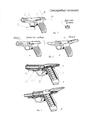
На рис. 1. представлен внешний вид пистолета (возможный вариант).In fig. 1. presents the appearance of the gun (possible).
Рис. 2 демонстрирует положение центра тяжести затвора относительно оси ствола, и изменение плеча отдачи при выстреле.Fig. 2 shows the position of the center of gravity of the shutter relative to the axis of the barrel, and the change in the recoil arm when fired.
На рис. 3 представлена общая возможная схема устройства пистолета в разрезе.In fig. 3 shows a general possible sectional diagram of a pistol device.
Пистолет (рис. 1) состоит из рамки 1 с установленным на ней стволом, и затвора 2, перемещающегося по дугообразным направляющим 3 рамки. Поз. 4 обозначает возможный способ крепления тактического фонаря или лазерного целеуказателя (ЛЦУ).The gun (Fig. 1) consists of a
На данном рисунке представлен вариант, в котором направляющие рамки охватывают направляющие затвора с наружной стороны, что проиллюстрировано на виде сзади. Это позволяет минимизировать габариты затыльника при обеспечении безопасности для руки стреляющего. В передней части рамки также имеются направляющие затвора. Угол ![]()
![]()
На рис. 2а изображен пистолет в момент выстрела. Усилие отдачи F направлено вдоль оси ствола. В силу того, что передняя часть затвора имеет П-образное сечение, а масса его задней части также смещена вверх, центр масс затвора расположен выше оси ствола на расстоянии L. Поэтому в момент выстрела сила отдачи не только придает импульс затвору для движения назад, но и обеспечивает дополнительный вращательный момент относительно центра масс затвора на плече L, в направлении против часовой стрелки. Это благоприятно влияет на движение затвора по дугообразным направляющим, снижая влияние силы трения затвора на направляющих, уменьшая подброс оружия и воздействие вертикальной составляющей усилия отдачи на руку стреляющего.In fig. 2a shows a gun at the time of the shot. The recoil force F is directed along the axis of the barrel. Due to the fact that the front part of the shutter has a U-shaped cross section, and the mass of its rear part is also shifted up, the center of mass of the shutter is located above the axis of the barrel at a distance L. Therefore, at the moment of the shot, the recoil force not only gives an impulse to the shutter to move backward, but and provides additional torque relative to the center of mass of the shutter on the arm L, counterclockwise. This favorably affects the movement of the shutter along arched guides, reducing the influence of the friction force of the shutter on the guides, reducing the toss of the weapon and the effect of the vertical component of the recoil force on the firing hand.
На рис. 2б представлено положение частей оружия в конце отката затвора, перед его соударением с рамкой. (Прим.: На данном рисунке рамка несколько повернута назад (по час. стрелке) в соответствии с движением отдачи оружия.) В этот момент, как правило, возникает основной удар в кисть стрелка. Как следует из рисунка, плечо отдачи R, представляющее расстояние от центра масс затвора, в котором приложена сила инерции G, до поверхности затыльника рукоятки, фактически не отличается от такового для прототипа ГШ-18 и др. аналогов. Таким образом, несмотря на минимальное плечо отдачи перед выстрелом, наличие плеча R в конце отката затвора уменьшит ударное воздействие на кисть стрелка до приемлемых величин. Это является важным положительным свойством предлагаемого изобретения, на которое следует обратить особое внимание при конструировании и расчетах, по возможности смещая центр тяжести затвора вверх.In fig. 2b shows the position of the parts of the weapon at the end of the recoil of the bolt, before its collision with the frame. (Note: In this figure, the frame is slightly turned back (clockwise) in accordance with the movement of the recoil of the weapon.) At this point, as a rule, the main blow to the hand of the hand occurs. As follows from the figure, the recoil arm R, representing the distance from the center of mass of the shutter, in which the inertia force G is applied, to the surface of the butt plate of the handle, does not actually differ from that for the prototype GSh-18 and other analogues. Thus, despite the minimum recoil arm before the shot, the presence of a shoulder R at the end of the shutter recoil will reduce the impact on the shooter's hand to acceptable values. This is an important positive feature of the invention, which should be paid special attention in the design and calculations, if possible shifting the center of gravity of the shutter up.
При необходимости ударное воздействие на кисть стрелка можно дополнительно снизить применением эластичной вставки на затыльнике рукоятки. Достигаемая компактность задней части оружия позволяет это сделать без ущерба для его эргономики.If necessary, the impact on the arrow can be further reduced by using an elastic insert on the butt plate of the handle. The achieved compactness of the rear of the weapon allows this to be done without compromising its ergonomics.
Пистолет работает следующим образом (рис. 2). При выстреле срабатывает ударник и накалывает капсюль патрона, происходит выстрел. Усилие отдачи отбрасывает затвор, и он движется по дугообразным направляющим назад, при этом ствол наклоняется дульной частью вниз. Далее выбрасывается стреляная гильза, взводится ударник, затем при движении затвора вперед под действием возвратной пружины очередной патрон выталкивается из загибов магазина и досылается в патронник.The gun works as follows (Fig. 2). When fired, the firing pin fires and punches the cartridge capsule, a shot occurs. The recoil force throws the bolt back, and it moves along the arcuate guides back, while the barrel tilts down the muzzle. Next, the fired cartridge case is thrown out, the drummer cockes, then when the shutter moves forward under the action of the return spring, the next cartridge is pushed out of the bends of the store and sent to the chamber.
Наклон ствола дульной частью вниз при откате затвора применен для более надежного извлечения гильзы, во избежание ее перекоса из-за несоосности ствола и траектории движения затвора по дуге. Предполагается также, что это может несколько снизить подброс оружия при выстреле и способствовать возвращению ствола на линию прицеливания после цикла перезарядки.The inclination of the barrel with the muzzle downward when rolling back the shutter was used to more reliably remove the liner, in order to avoid its skew due to misalignment of the barrel and the trajectory of the shutter in an arc. It is also assumed that this can somewhat reduce the toss of the weapon during firing and contribute to the return of the barrel to the line of sight after a reload cycle.
Однако, если разработать конструкцию гильзовыбрасывателя, обеспечивающую надежное извлечение гильзы при несоосности оси ствола и траектории движения зеркала затвора при его откате, наклон ствола не потребуется.However, if you develop the design of the sleeve ejector, which provides reliable removal of the sleeve when the axis of the barrel is misaligned and the trajectory of the shutter mirror moves when it is rolled back, the barrel will not be tilted.
Запирание канала ствола может производиться как свободным затвором, так и коротким ходом ствола в различных вариантах, а также полусвободным затвором, газовым торможением затвора и т.д.The barrel bore can be locked both by a free shutter and by a short stroke of the barrel in various versions, as well as by a half-free shutter, gas braking of the shutter, etc.
На рис. 3 представлена возможная схема устройства пистолета в разрезе.In fig. 3 shows a possible sectional diagram of a pistol device.
На рис. 3а. представлена возможная схема устройства пистолета в разрезе.In fig. 3a. A possible sectional diagram of a pistol device is presented.
Ствол пистолета установлен в рамке на цапфах 5 с возможностью поворота дульной частью вперед и короткого хода назад. В исходном положении ствол замкнут с затвором упором качающегося запирающего рычага 6 в нижнюю переднюю часть затвора. Скошенная поверхность 7 рамки служит для отпирания затвора при коротком ходе ствола. Плоская пружина 8 введена в конструкцию для поджатия ствола в переднее положение. Поз. 9 условно обозначает шептало, поз. 10 - пружину и ударник УСМ.The barrel of the gun is mounted in a frame on the
При выстреле ствол и затвор некоторое расстояние движутся вместе, сжимая пружину 8. Затем скос 7 опускает передний конец рычага 6 и далее затвор откатывается назад по дугообразным направляющим, и совершает цикл перезарядки.When fired, the barrel and the bolt move for some distance together, compressing the
На рис. 3б. представлено положение частей оружия в конце отката затвора.In fig. 3b. presents the position of the parts of the weapon at the end of the shutter recoil.
Запирающий рычаг опущен вниз. Ствол смещен назад на величину короткого хода. Затвор находится в заднем положении. Прим.: Возвратная пружина условно не показана.The locking lever is lowered down. The barrel is shifted backward by the amount of short stroke. The shutter is in the rear position. Note: The return spring is not conventionally shown.
Ударно-спусковой механизм 10, ввиду уменьшения пространства в затворе для его размещения, может быть выполнен с некоторым наклоном оси ударника к оси ствола. Подобные конструкции известны, напр., спортивный пистолет Хайдурова, пистолет Savage 1907, охотничьи ружья, и др.The
Как видно из рис. 1 и 2, предлагаемый вариант позволяет значительно уменьшить плечо отдачи, т.е. расстояние между осью ствола и затыльником рукоятки. Также, при хвате рукоятки кистью стрелка имеется небольшой наклон указательного пальца стрелка по линии от затыльника рукоятки к спусковому крючку относительно оси ствола. Это характерно для спортивных пистолетов, где эргономике оружия уделяется особое внимание.As can be seen from fig. 1 and 2, the proposed option can significantly reduce the recoil arm, i.e. the distance between the axis of the barrel and the back plate of the handle. Also, when grabbing the handle with the arrow, there is a slight tilt of the index finger arrow along the line from the butt plate of the handle to the trigger relative to the axis of the barrel. This is characteristic of sports pistols, where special attention is paid to the ergonomics of weapons.
Таким образом, данное конструкторское решение может снизить подброс оружия и улучшить его точность и управляемость при стрельбе. На данных рисунках, в целом выполненных в реальных пропорциях пистолета, видно, что ось канала ствола находится на уровне поверхности затыльника, и таким образом, плечо отдачи можно условно считать равным или близким нулю.Thus, this design decision can reduce the planting of weapons and improve its accuracy and controllability when shooting. In these figures, generally performed in real proportions of the gun, it can be seen that the axis of the bore is at the level of the surface of the butt plate, and thus, the recoil arm can be arbitrarily considered equal to or close to zero.
Также при использовании данного изобретения существенно уменьшаются габариты задней части пистолета, что делает его более компактным. Это имеет значение, в том числе, при создании компактных пистолетов для скрытого ношения - одного из направлений на рынке боевого и гражданского оружия для самообороны.Also, when using this invention, the dimensions of the rear of the gun are significantly reduced, which makes it more compact. This is important, including when creating compact pistols for covert carrying - one of the areas on the market of military and civilian weapons for self-defense.
Claims (5)
Priority Applications (1)
| Application Number | Priority Date | Filing Date | Title |
|---|---|---|---|
| RU2016137244A RU2675309C2 (en) | 2016-09-16 | 2016-09-16 | Self-loading pistol |
Applications Claiming Priority (1)
| Application Number | Priority Date | Filing Date | Title |
|---|---|---|---|
| RU2016137244A RU2675309C2 (en) | 2016-09-16 | 2016-09-16 | Self-loading pistol |
Publications (3)
| Publication Number | Publication Date |
|---|---|
| RU2016137244A RU2016137244A (en) | 2018-03-19 |
| RU2016137244A3 RU2016137244A3 (en) | 2018-10-23 |
| RU2675309C2 true RU2675309C2 (en) | 2018-12-19 |
Family
ID=61627238
Family Applications (1)
| Application Number | Title | Priority Date | Filing Date |
|---|---|---|---|
| RU2016137244A RU2675309C2 (en) | 2016-09-16 | 2016-09-16 | Self-loading pistol |
Country Status (1)
| Country | Link |
|---|---|
| RU (1) | RU2675309C2 (en) |
Cited By (1)
| Publication number | Priority date | Publication date | Assignee | Title |
|---|---|---|---|---|
| RU2774999C1 (en) * | 2021-12-09 | 2022-06-27 | Александр Петрович Шарыпкин | Method for reducing the toss of a handgun with a sliding bolt |
Citations (4)
| Publication number | Priority date | Publication date | Assignee | Title |
|---|---|---|---|---|
| US4934247A (en) * | 1988-05-04 | 1990-06-19 | Armando Piscetta | Locking assembly for weapon barrels |
| US5513550A (en) * | 1993-05-04 | 1996-05-07 | Field; Roger C. | Firearm with pivoting barrel |
| RU2180952C1 (en) * | 2001-02-26 | 2002-03-27 | Курсаков Александр Александрович | Method for operation of weapon automatic equipment and automatic revolver based on it |
| RU2184334C2 (en) * | 2000-03-30 | 2002-06-27 | Котельников Василий Иванович | Pistol |
-
2016
- 2016-09-16 RU RU2016137244A patent/RU2675309C2/en active
Patent Citations (4)
| Publication number | Priority date | Publication date | Assignee | Title |
|---|---|---|---|---|
| US4934247A (en) * | 1988-05-04 | 1990-06-19 | Armando Piscetta | Locking assembly for weapon barrels |
| US5513550A (en) * | 1993-05-04 | 1996-05-07 | Field; Roger C. | Firearm with pivoting barrel |
| RU2184334C2 (en) * | 2000-03-30 | 2002-06-27 | Котельников Василий Иванович | Pistol |
| RU2180952C1 (en) * | 2001-02-26 | 2002-03-27 | Курсаков Александр Александрович | Method for operation of weapon automatic equipment and automatic revolver based on it |
Cited By (2)
| Publication number | Priority date | Publication date | Assignee | Title |
|---|---|---|---|---|
| RU2774999C1 (en) * | 2021-12-09 | 2022-06-27 | Александр Петрович Шарыпкин | Method for reducing the toss of a handgun with a sliding bolt |
| RU2783410C1 (en) * | 2022-01-11 | 2022-11-14 | Игорь Алексеевич Иванов | Gun |
Also Published As
| Publication number | Publication date |
|---|---|
| RU2016137244A (en) | 2018-03-19 |
| RU2016137244A3 (en) | 2018-10-23 |
Similar Documents
| Publication | Publication Date | Title |
|---|---|---|
| US10551137B2 (en) | Semi-automatic pistol | |
| US8132352B2 (en) | Handgun system | |
| US7398723B1 (en) | Trigger forward displacement system and method | |
| CN102245997B (en) | Delayed blowback firearms with novel mechanisms for control of recoil and muzzle climb | |
| US7673553B2 (en) | Barrel link for a semiautomatic weapon | |
| US20120085010A1 (en) | Semi-automatic handgun apparatus and method | |
| US10641562B2 (en) | Firearm with recoil mitigation | |
| US8997390B1 (en) | Trigger mechanism with cam surface sear | |
| US11306986B1 (en) | Transformer sub-pistol firearm | |
| US10436531B2 (en) | Recoil apparatus for firearms | |
| US20040159033A1 (en) | Semiautomatic handgun | |
| RU2717112C1 (en) | Firearm with barrel forward stroke | |
| RU2703371C1 (en) | Automatic firearm with inertia automation and recoil system in the form of constant force | |
| RU2675309C2 (en) | Self-loading pistol | |
| RU2488064C2 (en) | Fire arms piece | |
| US11530889B1 (en) | Firearm, trigger assembly, and trigger assembly hammer | |
| WO2024258375A1 (en) | A new locked breech mechanism for firearms | |
| RU2814289C2 (en) | Gun | |
| RU2422752C2 (en) | Sub-machine gun | |
| RU2520638C1 (en) | Automatic gun | |
| RU2659724C1 (en) | Small arms | |
| RU2776331C1 (en) | Submachine gun | |
| RU2284441C2 (en) | Combination rifle | |
| RU2818974C1 (en) | Automatic small arms | |
| RU2453787C1 (en) | Autoloading pistol |