RU2673503C1 - Method of measuring effort applied to bearing with static and dynamic loading using strain gauges - Google Patents
Method of measuring effort applied to bearing with static and dynamic loading using strain gauges Download PDFInfo
- Publication number
- RU2673503C1 RU2673503C1 RU2017142243A RU2017142243A RU2673503C1 RU 2673503 C1 RU2673503 C1 RU 2673503C1 RU 2017142243 A RU2017142243 A RU 2017142243A RU 2017142243 A RU2017142243 A RU 2017142243A RU 2673503 C1 RU2673503 C1 RU 2673503C1
- Authority
- RU
- Russia
- Prior art keywords
- bearing
- strain gauges
- calibration
- rotation
- radial
- Prior art date
Links
- 238000000034 method Methods 0.000 title claims abstract description 13
- 230000003068 static effect Effects 0.000 title claims description 4
- 238000005096 rolling process Methods 0.000 claims abstract description 18
- 238000005259 measurement Methods 0.000 abstract description 7
- 239000000126 substance Substances 0.000 abstract 1
- 238000009434 installation Methods 0.000 description 3
- 238000012360 testing method Methods 0.000 description 3
- 230000000712 assembly Effects 0.000 description 1
- 238000000429 assembly Methods 0.000 description 1
- 244000309464 bull Species 0.000 description 1
- 238000011089 mechanical engineering Methods 0.000 description 1
- 238000001228 spectrum Methods 0.000 description 1
Images

Classifications
-
- G—PHYSICS
- G01—MEASURING; TESTING
- G01L—MEASURING FORCE, STRESS, TORQUE, WORK, MECHANICAL POWER, MECHANICAL EFFICIENCY, OR FLUID PRESSURE
- G01L1/00—Measuring force or stress, in general
- G01L1/20—Measuring force or stress, in general by measuring variations in ohmic resistance of solid materials or of electrically-conductive fluids; by making use of electrokinetic cells, i.e. liquid-containing cells wherein an electrical potential is produced or varied upon the application of stress
- G01L1/22—Measuring force or stress, in general by measuring variations in ohmic resistance of solid materials or of electrically-conductive fluids; by making use of electrokinetic cells, i.e. liquid-containing cells wherein an electrical potential is produced or varied upon the application of stress using resistance strain gauges
Landscapes
- Physics & Mathematics (AREA)
- General Physics & Mathematics (AREA)
- Force Measurement Appropriate To Specific Purposes (AREA)
- Rolling Contact Bearings (AREA)
Abstract
Description
Изобретение относится к способам измерения осевых и радиальных сил, воздействующих на работающий подшипник качения. Изобретение может найти применение во всех узлах, имеющих подшипники качения.The invention relates to methods for measuring axial and radial forces acting on a running rolling bearing. The invention may find application in all assemblies having rolling bearings.
Известен способ измерения осевого усилия тензометрическими кольцами («Основы конструирования авиационных двигателей и энергетических установок» авторы А.А. Иноземцев, М.А. Нихамкин, В.Л. Сандрацкий. - М.: машиностроение, 2008. - Т. 1. - 201 с.) располагаемыми с обеих сторон радиально-упорного подшипника качения. Тензометрические кольца представляют собой плоские упругие кольца с упорными площадками. На плоских поверхностях между опорными выступами устанавливаются тензодатчики. При приложении осевого усилия на опорные выступы происходит деформация площадок с тензодатчиками с появлением сжимающих напряжений с одной стороны площадки и растягивающих - с другой. Показания по указанным деформациям градуируют на технологической установке. Основным недостатком указанного способа является необходимость использования технологической опоры в двигателе, в которой следует установить тензометрические кольца, что значительно увеличивает массу опоры, и дает возможность измерения только осевой силы.A known method of measuring axial force by tensometric rings ("Fundamentals of the design of aircraft engines and power plants" authors AA Inozemtsev, MA Nikhamkin, VL Sandratsky. - M .: mechanical engineering, 2008. - T. 1. - 201 s.) Located on both sides of the angular contact rolling bearing. Strain rings are flat elastic rings with thrust pads. Strain gages are installed on flat surfaces between the support protrusions. When an axial force is applied to the support protrusions, deformation of the sites with strain gauges occurs with the appearance of compressive stresses on one side of the site and tensile stresses on the other. Indications for these deformations are graduated on the technological installation. The main disadvantage of this method is the need to use a technological support in the engine, in which strain gauge rings should be installed, which significantly increases the mass of the support and makes it possible to measure only axial force.
Наиболее близким к изобретению является способ измерения радиальных сил, действующих на подшипник качения при статическом и динамическом нагружении с использованием тензодатчиков сопротивления (авторское свидетельство №212594, опубл. 29.11.1968, бюл. №9, МПК G01M 13/04), при котором тензодатчики установлены на неподвижном кольце подшипника. Основным недостатком данного способа является отсутствие возможности измерения осевых нагрузок, т.к. данное расположения тензодатчиков позволяет выполнять измерения только радиальных нагрузок.Closest to the invention is a method of measuring the radial forces acting on a rolling bearing under static and dynamic loading using resistance strain gauges (copyright certificate No. 212594, publ. 11/29/1968, bull. No. 9, IPC G01M 13/04), in which load cells mounted on a stationary bearing ring. The main disadvantage of this method is the inability to measure axial loads, because This arrangement of load cells allows only radial loads to be measured.
Техническим результатом, на достижение которого направлено изобретение, является возможность одновременного измерения как радиальной, так и осевой сил, воздействующих на радиально-упорный подшипник качения, с использованием градуировочных коэффициентов.The technical result to which the invention is directed is the possibility of simultaneous measurement of both radial and axial forces acting on an angular contact rolling bearing using calibration factors.
Технический результат достигается тем, что в способе измерения сил, действующих на подшипник качения при статическом и динамическом нагружении с использованием тензодатчиков сопротивления, при котором тензодатчики установлены на наружной посадочной поверхности неподвижного кольца подшипника, в отличие от известного, тензодатчики устанавливают на наклонные к оси вращения подшипника участки наружной посадочной поверхности неподвижного кольца, при этом для тензодатчиков выполняют градуировку усилий, соответствующих рабочим частотам вращения, нагрузкам и тепловому состоянию подшипника при работе в узле.The technical result is achieved by the fact that in the method of measuring the forces acting on a rolling bearing under static and dynamic loading using resistance strain gauges, in which the strain gauges are mounted on the outer seating surface of the stationary bearing ring, in contrast to the known one, the load cells are mounted on bearings inclined to the axis of rotation sections of the outer landing surface of the fixed ring, while the strain gauges perform graduation of efforts corresponding to the working frequency rotation, and thermal loads during operation of the bearing in the node.
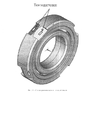
На фигурах показаны:The figures show:
Фиг. 1 - пример схемы расположения тензодатчиков.FIG. 1 is an example of a strain gauge arrangement.
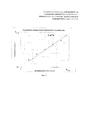
Фиг. 2 - пример спектра амплитудно-частотной характеристики динамических напряжений на одной из частот вращения ротора.FIG. 2 is an example of a spectrum of the amplitude-frequency characteristic of dynamic stresses at one of the rotor rotation frequencies.
Фиг. 3 - пример зависимости динамических напряжений от осевого усилия.FIG. 3 is an example of the dependence of dynamic stresses on axial force.
Способ осуществляется следующим образом.The method is as follows.
На неподвижном кольце, под углом к оси вращения выполняются пазы, в которые устанавливаются тензодатчики сопротивления. Для тензодатчиков выполняется градуировка усилий для определения градуировочных коэффициентов.On a fixed ring, at an angle to the axis of rotation, grooves are made in which resistance strain gauges are installed. For load cells, a force calibration is performed to determine calibration factors.
Для повышения точности градуировки, например, на технологической установке или в составе двигателя, режимы градуировки должны соответствовать рабочим частотам вращения, нагрузкам и тепловому состоянию подшипников при работе в узле.To increase the accuracy of calibration, for example, on a technological installation or as part of an engine, the calibration regimes should correspond to the operating frequencies of rotation, loads and thermal state of the bearings during operation in the assembly.
При градуировке по результатам измерений динамических напряжений в каждый момент времени получают амплитудно-частотную характеристику, в которой полезными сигналами являются амплитуды напряжений на частотах прокатывания тел качения по дорожкам качения наружных колец.When calibrating according to the results of measurements of dynamic stresses at each moment of time, an amplitude-frequency characteristic is obtained, in which voltage amplitudes at the frequencies of rolling of rolling elements along the raceways of the outer rings are useful signals.
Градуировочный коэффициент для усилия определяется при сопоставлении амплитуды напряжений на частоте прокатывания тел качения и эталонным усилием на технологической установке в каждый момент времени.The calibration factor for the force is determined by comparing the amplitude of the stresses at the rolling frequency of the rolling elements and the reference force at the process plant at any given time.
Пример.Example.
С помощью динамического тензометрирования выполняется измерения, например, осевого усилия в стендовых условиях на двигателе при проведении предварительных испытаний (фиг. 1). Величины измеряемых осевых нагрузок определяются по записям на контрольно-измерительную аппаратуру величины динамических напряжений, измеренных тензодатчиками, расположенными на наружном кольце подшипника.Using dynamic strain gauging, measurements are made, for example, of axial force in bench conditions on the engine during preliminary tests (Fig. 1). The values of the measured axial loads are determined by the records on the instrumentation of the magnitude of the dynamic stresses measured by strain gauges located on the outer ring of the bearing.
Перед проведением испытаний подшипник дорабатывается: в наружном кольце подшипника на посадочной поверхности под углом к оси вращения выполняются пазы, в которые устанавливаются тензодатчики, которые размещаются в зоне наибольших расчетных напряжений, определенных на основании 3D математического моделирования напряженно-деформированного состояния наружного кольца.Before testing, the bearing is finalized: in the outer ring of the bearing on the landing surface at an angle to the axis of rotation, grooves are made in which load cells are installed, which are placed in the zone of the highest design stresses, determined on the basis of 3D mathematical modeling of the stress-strain state of the outer ring.
Для определения зависимости между показаниями тензодатчиков и величиной осевого усилия перед испытаниями в составе ГТД выполняется градуировка. Градуировка показаний тензодатчиков осуществляется на специальной технологической установке в диапазоне рабочих частот вращения ротора ГТД и в диапазоне ожидаемых величин осевого усилия. Градуировка тензодатчиков выполняется в два этапа: при действии осевого усилия, как в сторону компрессора, так и в сторону турбины. Для повышения точности градуировки напряжения, записанные всеми тензодатчиками, усредняются.To determine the relationship between the readings of the load cells and the magnitude of the axial force before testing as part of the gas turbine engine, a calibration is performed. Calibration of the load cell readings is carried out on a special technological installation in the range of working frequencies of the rotor of the gas turbine engine and in the range of the expected values of the axial force. Strain gauges are calibrated in two stages: under the action of axial force, both towards the compressor and towards the turbine. To improve the accuracy of calibration, the voltages recorded by all load cells are averaged.
По результатам градуировки строится зависимость динамических напряжений с частотой прокатывания шаров от осевого усилия (фиг. 2, фиг. 3) и далее определяется линейный градуировочный коэффициент (К). Для тензодатчиков со стороны компрессора и со стороны турбины определяются свои градуировочные коэффициенты. В процессе проведения градуировки, для каждого отдельного подшипника определяется свой градуировочный коэффициент.According to the results of calibration, the dependence of dynamic stresses with the frequency of rolling the balls on the axial force (Fig. 2, Fig. 3) is built and then a linear calibration coefficient (K) is determined. For load cells on the compressor side and on the turbine side, their calibration coefficients are determined. During the calibration process, for each individual bearing its own calibration coefficient is determined.
По результатам измерений динамических напряжений в каждый момент времени получают амплитудно-частотную характеристику, в которой полезным сигналом является амплитуда напряжений на частоте прокатывания шариков по наружной обойме. Амплитуда динамических напряжений с частотой прокатывания шаров пропорциональна величине осевой нагрузки. По полученной амплитуде, с помощью градуировочного коэффициента, вычисляется действующее осевое усилие на подшипник в каждый момент времени и направление его действия. При этом погрешность измерений осевого усилия не превышает 10%.According to the results of measurements of dynamic stresses at each moment of time, an amplitude-frequency characteristic is obtained in which the voltage amplitude at the frequency of rolling the balls along the outer cage is a useful signal. The amplitude of dynamic stresses with a rolling frequency of balls is proportional to the magnitude of the axial load. Based on the obtained amplitude, using the calibration factor, the effective axial force on the bearing at each moment in time and its direction of action are calculated. In this case, the measurement error of the axial force does not exceed 10%.
Таким образом, данное техническое решение позволяет выполнить измерения с использованием градуировочных коэффициентов, как осевой силы, воздействующей на радиально-упорный подшипник качения, так и радиальной.Thus, this technical solution allows you to perform measurements using calibration factors, both axial force acting on the angular contact rolling bearing, and radial.
Claims (1)
Priority Applications (1)
| Application Number | Priority Date | Filing Date | Title |
|---|---|---|---|
| RU2017142243A RU2673503C1 (en) | 2017-12-04 | 2017-12-04 | Method of measuring effort applied to bearing with static and dynamic loading using strain gauges |
Applications Claiming Priority (1)
| Application Number | Priority Date | Filing Date | Title |
|---|---|---|---|
| RU2017142243A RU2673503C1 (en) | 2017-12-04 | 2017-12-04 | Method of measuring effort applied to bearing with static and dynamic loading using strain gauges |
Publications (1)
| Publication Number | Publication Date |
|---|---|
| RU2673503C1 true RU2673503C1 (en) | 2018-11-27 |
Family
ID=64556573
Family Applications (1)
| Application Number | Title | Priority Date | Filing Date |
|---|---|---|---|
| RU2017142243A RU2673503C1 (en) | 2017-12-04 | 2017-12-04 | Method of measuring effort applied to bearing with static and dynamic loading using strain gauges |
Country Status (1)
| Country | Link |
|---|---|
| RU (1) | RU2673503C1 (en) |
Cited By (4)
| Publication number | Priority date | Publication date | Assignee | Title |
|---|---|---|---|---|
| RU2729592C1 (en) * | 2019-11-12 | 2020-08-11 | Публичное акционерное общество "ОДК - Уфимское моторостроительное производственное объединение" (ПАО "ОДК-УМПО") | Method of determining axial force acting on turbomachine rotor during its operation |
| RU199131U1 (en) * | 2020-02-27 | 2020-08-18 | Публичное Акционерное Общество "Одк-Сатурн" | A device for measuring the forces acting on the rotor support of a gas turbine engine using dynamic strain gauge |
| CN113155454A (en) * | 2021-02-03 | 2021-07-23 | 浙江万向精工有限公司 | Strain calibration method of dynamic test bed of hub bearing |
| RU2789616C1 (en) * | 2022-01-14 | 2023-02-06 | Публичное Акционерное Общество "Одк-Сатурн" | Method for diagnostics of the rolling element jams in the bearing |
Citations (2)
| Publication number | Priority date | Publication date | Assignee | Title |
|---|---|---|---|---|
| SU212594A1 (en) * | М. У. Кацнельсон, М. А. Павловской, Б. А. Селиверстов , Ю. П. Стегайлов | METHOD OF MEASURING RADIAL FORCES ACTING ON ROLLING BEARING | ||
| SU767346A1 (en) * | 1977-12-14 | 1980-09-30 | Научно-исследовательский и проектно-конструкторский институт обогащения твердых горючих ископаемых | Method and device for monitoring position of working member of mining machine with respect to the coal-rock boundary |
-
2017
- 2017-12-04 RU RU2017142243A patent/RU2673503C1/en active
Patent Citations (2)
| Publication number | Priority date | Publication date | Assignee | Title |
|---|---|---|---|---|
| SU212594A1 (en) * | М. У. Кацнельсон, М. А. Павловской, Б. А. Селиверстов , Ю. П. Стегайлов | METHOD OF MEASURING RADIAL FORCES ACTING ON ROLLING BEARING | ||
| SU767346A1 (en) * | 1977-12-14 | 1980-09-30 | Научно-исследовательский и проектно-конструкторский институт обогащения твердых горючих ископаемых | Method and device for monitoring position of working member of mining machine with respect to the coal-rock boundary |
Non-Patent Citations (1)
| Title |
|---|
| "Основы конструирования авиационных двигателей и энергетических установок", авторы А.А. Иноземцев, М.А. Нихамкин, В.Л. Сандрацкий. - М.: машиностроение, 2008. - Т. 1. - 201 с. * |
Cited By (4)
| Publication number | Priority date | Publication date | Assignee | Title |
|---|---|---|---|---|
| RU2729592C1 (en) * | 2019-11-12 | 2020-08-11 | Публичное акционерное общество "ОДК - Уфимское моторостроительное производственное объединение" (ПАО "ОДК-УМПО") | Method of determining axial force acting on turbomachine rotor during its operation |
| RU199131U1 (en) * | 2020-02-27 | 2020-08-18 | Публичное Акционерное Общество "Одк-Сатурн" | A device for measuring the forces acting on the rotor support of a gas turbine engine using dynamic strain gauge |
| CN113155454A (en) * | 2021-02-03 | 2021-07-23 | 浙江万向精工有限公司 | Strain calibration method of dynamic test bed of hub bearing |
| RU2789616C1 (en) * | 2022-01-14 | 2023-02-06 | Публичное Акционерное Общество "Одк-Сатурн" | Method for diagnostics of the rolling element jams in the bearing |
Similar Documents
| Publication | Publication Date | Title |
|---|---|---|
| Hou et al. | Measurement of load distribution in a cylindrical roller bearing with an instrumented housing: Finite element validation and experimental study | |
| CN103278131B (en) | A kind of axial deformation of rock sample measuring method | |
| RU2673503C1 (en) | Method of measuring effort applied to bearing with static and dynamic loading using strain gauges | |
| Zhang et al. | Identification of bearing load by three section strain gauge method: Theoretical and experimental research | |
| RU2729592C1 (en) | Method of determining axial force acting on turbomachine rotor during its operation | |
| Li et al. | Measured and investigated nonlinear dynamics parameters on bolted flange joints of combined rotor | |
| CN112284592A (en) | Force measuring method for high-precision vertical force measurement longitudinal and multidirectional movable spherical support | |
| CN105954036A (en) | Detection device and method for radial stiffness of bearing ring with mounting flange | |
| Weidinger et al. | Development of a torque calibration procedure under rotation for nacelle test benches | |
| CN112345245A (en) | A bearing static stiffness test device and its test method | |
| Majzoobi et al. | A new device for fretting fatigue testing | |
| Deng et al. | Design and Performance Research of a New Type of Spherical Force-Measuring Bearing of Bridges Based on Button Type Microsensor | |
| RU199131U1 (en) | A device for measuring the forces acting on the rotor support of a gas turbine engine using dynamic strain gauge | |
| Keller et al. | Gearbox reliability collaborative investigation of high-speed-shaft bearing loads | |
| Kushner | Dynamic strain measurement of propeller shaft vibrations | |
| Wang et al. | An FBG-based method for load measurement of a cylindrical rolling element bearing | |
| Bachschmid et al. | Deflections and strains in cracked shafts due to rotating loads: a numerical and experimental analysis | |
| Wang et al. | Measurement of bearing reaction force by distributed strain variation | |
| CN214121593U (en) | Bearing static rigidity test device | |
| CN115539318B (en) | A wind turbine tower load monitoring system and method | |
| CN115950581A (en) | Calibration device and method for rotor shaft squirrel cage force measurement structure | |
| Bian et al. | Ultrasonic detection method of contact load between rollers and raceways of wind turbine main shaft bearings | |
| Pasanen et al. | Development of a test device for the evaluation of fretting in point contact | |
| RU2332650C1 (en) | Method of determination of body static moment | |
| RU2550826C2 (en) | Method to measure stresses in structure without removal of static loads |