RU2671219C1 - Pneumatic tyre - Google Patents
Pneumatic tyre Download PDFInfo
- Publication number
- RU2671219C1 RU2671219C1 RU2017122751A RU2017122751A RU2671219C1 RU 2671219 C1 RU2671219 C1 RU 2671219C1 RU 2017122751 A RU2017122751 A RU 2017122751A RU 2017122751 A RU2017122751 A RU 2017122751A RU 2671219 C1 RU2671219 C1 RU 2671219C1
- Authority
- RU
- Russia
- Prior art keywords
- tire
- recesses
- area
- contact
- zones
- Prior art date
Links
- 238000009423 ventilation Methods 0.000 claims description 9
- 239000000126 substance Substances 0.000 abstract description 3
- XLYOFNOQVPJJNP-UHFFFAOYSA-N water Substances O XLYOFNOQVPJJNP-UHFFFAOYSA-N 0.000 description 69
- 238000010586 diagram Methods 0.000 description 34
- 230000015572 biosynthetic process Effects 0.000 description 19
- 239000010410 layer Substances 0.000 description 10
- 238000012360 testing method Methods 0.000 description 9
- 239000000835 fiber Substances 0.000 description 6
- 239000011324 bead Substances 0.000 description 4
- 238000005096 rolling process Methods 0.000 description 4
- 230000003068 static effect Effects 0.000 description 4
- 229910000831 Steel Inorganic materials 0.000 description 3
- 238000010521 absorption reaction Methods 0.000 description 3
- 238000010073 coating (rubber) Methods 0.000 description 3
- 238000013461 design Methods 0.000 description 3
- 230000000694 effects Effects 0.000 description 3
- 239000000945 filler Substances 0.000 description 3
- 239000000463 material Substances 0.000 description 3
- 239000002689 soil Substances 0.000 description 3
- 239000010959 steel Substances 0.000 description 3
- 230000035939 shock Effects 0.000 description 2
- 238000004073 vulcanization Methods 0.000 description 2
- 241000264877 Hippospongia communis Species 0.000 description 1
- 239000004677 Nylon Substances 0.000 description 1
- 229920000297 Rayon Polymers 0.000 description 1
- 239000004760 aramid Substances 0.000 description 1
- 229920003235 aromatic polyamide Polymers 0.000 description 1
- 238000004891 communication Methods 0.000 description 1
- 238000010276 construction Methods 0.000 description 1
- 230000006866 deterioration Effects 0.000 description 1
- 230000002542 deteriorative effect Effects 0.000 description 1
- 230000008034 disappearance Effects 0.000 description 1
- 238000006073 displacement reaction Methods 0.000 description 1
- 238000005516 engineering process Methods 0.000 description 1
- 239000011159 matrix material Substances 0.000 description 1
- 238000005259 measurement Methods 0.000 description 1
- 239000000155 melt Substances 0.000 description 1
- 238000000465 moulding Methods 0.000 description 1
- 229920001778 nylon Polymers 0.000 description 1
- 238000011056 performance test Methods 0.000 description 1
- 229920000728 polyester Polymers 0.000 description 1
- 230000000717 retained effect Effects 0.000 description 1
- 239000002356 single layer Substances 0.000 description 1
- 230000001629 suppression Effects 0.000 description 1
- 238000009827 uniform distribution Methods 0.000 description 1
Images


Classifications
-
- B—PERFORMING OPERATIONS; TRANSPORTING
- B60—VEHICLES IN GENERAL
- B60C—VEHICLE TYRES; TYRE INFLATION; TYRE CHANGING; CONNECTING VALVES TO INFLATABLE ELASTIC BODIES IN GENERAL; DEVICES OR ARRANGEMENTS RELATED TO TYRES
- B60C11/00—Tyre tread bands; Tread patterns; Anti-skid inserts
- B60C11/03—Tread patterns
- B60C11/12—Tread patterns characterised by the use of narrow slits or incisions, e.g. sipes
- B60C11/1204—Tread patterns characterised by the use of narrow slits or incisions, e.g. sipes with special shape of the sipe
-
- B—PERFORMING OPERATIONS; TRANSPORTING
- B60—VEHICLES IN GENERAL
- B60C—VEHICLE TYRES; TYRE INFLATION; TYRE CHANGING; CONNECTING VALVES TO INFLATABLE ELASTIC BODIES IN GENERAL; DEVICES OR ARRANGEMENTS RELATED TO TYRES
- B60C11/00—Tyre tread bands; Tread patterns; Anti-skid inserts
- B60C11/02—Replaceable treads
-
- B—PERFORMING OPERATIONS; TRANSPORTING
- B60—VEHICLES IN GENERAL
- B60C—VEHICLE TYRES; TYRE INFLATION; TYRE CHANGING; CONNECTING VALVES TO INFLATABLE ELASTIC BODIES IN GENERAL; DEVICES OR ARRANGEMENTS RELATED TO TYRES
- B60C11/00—Tyre tread bands; Tread patterns; Anti-skid inserts
- B60C11/03—Tread patterns
- B60C11/0327—Tread patterns characterised by special properties of the tread pattern
- B60C11/0332—Tread patterns characterised by special properties of the tread pattern by the footprint-ground contacting area of the tyre tread
-
- B—PERFORMING OPERATIONS; TRANSPORTING
- B60—VEHICLES IN GENERAL
- B60C—VEHICLE TYRES; TYRE INFLATION; TYRE CHANGING; CONNECTING VALVES TO INFLATABLE ELASTIC BODIES IN GENERAL; DEVICES OR ARRANGEMENTS RELATED TO TYRES
- B60C11/00—Tyre tread bands; Tread patterns; Anti-skid inserts
- B60C11/03—Tread patterns
- B60C11/0306—Patterns comprising block rows or discontinuous ribs
-
- B—PERFORMING OPERATIONS; TRANSPORTING
- B60—VEHICLES IN GENERAL
- B60C—VEHICLE TYRES; TYRE INFLATION; TYRE CHANGING; CONNECTING VALVES TO INFLATABLE ELASTIC BODIES IN GENERAL; DEVICES OR ARRANGEMENTS RELATED TO TYRES
- B60C11/00—Tyre tread bands; Tread patterns; Anti-skid inserts
- B60C11/03—Tread patterns
- B60C11/032—Patterns comprising isolated recesses
-
- B—PERFORMING OPERATIONS; TRANSPORTING
- B60—VEHICLES IN GENERAL
- B60C—VEHICLE TYRES; TYRE INFLATION; TYRE CHANGING; CONNECTING VALVES TO INFLATABLE ELASTIC BODIES IN GENERAL; DEVICES OR ARRANGEMENTS RELATED TO TYRES
- B60C11/00—Tyre tread bands; Tread patterns; Anti-skid inserts
- B60C11/03—Tread patterns
- B60C11/0327—Tread patterns characterised by special properties of the tread pattern
- B60C11/033—Tread patterns characterised by special properties of the tread pattern by the void or net-to-gross ratios of the patterns
-
- B—PERFORMING OPERATIONS; TRANSPORTING
- B60—VEHICLES IN GENERAL
- B60C—VEHICLE TYRES; TYRE INFLATION; TYRE CHANGING; CONNECTING VALVES TO INFLATABLE ELASTIC BODIES IN GENERAL; DEVICES OR ARRANGEMENTS RELATED TO TYRES
- B60C11/00—Tyre tread bands; Tread patterns; Anti-skid inserts
- B60C11/03—Tread patterns
- B60C11/13—Tread patterns characterised by the groove cross-section, e.g. for buttressing or preventing stone-trapping
-
- B—PERFORMING OPERATIONS; TRANSPORTING
- B60—VEHICLES IN GENERAL
- B60C—VEHICLE TYRES; TYRE INFLATION; TYRE CHANGING; CONNECTING VALVES TO INFLATABLE ELASTIC BODIES IN GENERAL; DEVICES OR ARRANGEMENTS RELATED TO TYRES
- B60C11/00—Tyre tread bands; Tread patterns; Anti-skid inserts
- B60C11/03—Tread patterns
- B60C2011/0337—Tread patterns characterised by particular design features of the pattern
- B60C2011/0339—Grooves
- B60C2011/0341—Circumferential grooves
- B60C2011/0355—Circumferential grooves characterised by depth
-
- B—PERFORMING OPERATIONS; TRANSPORTING
- B60—VEHICLES IN GENERAL
- B60C—VEHICLE TYRES; TYRE INFLATION; TYRE CHANGING; CONNECTING VALVES TO INFLATABLE ELASTIC BODIES IN GENERAL; DEVICES OR ARRANGEMENTS RELATED TO TYRES
- B60C11/00—Tyre tread bands; Tread patterns; Anti-skid inserts
- B60C11/03—Tread patterns
- B60C2011/0337—Tread patterns characterised by particular design features of the pattern
- B60C2011/0339—Grooves
- B60C2011/0358—Lateral grooves, i.e. having an angle of 45 to 90 degees to the equatorial plane
- B60C2011/036—Narrow grooves, i.e. having a width of less than 3 mm
-
- B—PERFORMING OPERATIONS; TRANSPORTING
- B60—VEHICLES IN GENERAL
- B60C—VEHICLE TYRES; TYRE INFLATION; TYRE CHANGING; CONNECTING VALVES TO INFLATABLE ELASTIC BODIES IN GENERAL; DEVICES OR ARRANGEMENTS RELATED TO TYRES
- B60C11/00—Tyre tread bands; Tread patterns; Anti-skid inserts
- B60C11/03—Tread patterns
- B60C2011/0337—Tread patterns characterised by particular design features of the pattern
- B60C2011/0339—Grooves
- B60C2011/0358—Lateral grooves, i.e. having an angle of 45 to 90 degees to the equatorial plane
- B60C2011/0362—Shallow grooves, i.e. having a depth of less than 50% of other grooves
-
- B—PERFORMING OPERATIONS; TRANSPORTING
- B60—VEHICLES IN GENERAL
- B60C—VEHICLE TYRES; TYRE INFLATION; TYRE CHANGING; CONNECTING VALVES TO INFLATABLE ELASTIC BODIES IN GENERAL; DEVICES OR ARRANGEMENTS RELATED TO TYRES
- B60C11/00—Tyre tread bands; Tread patterns; Anti-skid inserts
- B60C11/03—Tread patterns
- B60C2011/0337—Tread patterns characterised by particular design features of the pattern
- B60C2011/0339—Grooves
- B60C2011/0381—Blind or isolated grooves
- B60C2011/0383—Blind or isolated grooves at the centre of the tread
-
- B—PERFORMING OPERATIONS; TRANSPORTING
- B60—VEHICLES IN GENERAL
- B60C—VEHICLE TYRES; TYRE INFLATION; TYRE CHANGING; CONNECTING VALVES TO INFLATABLE ELASTIC BODIES IN GENERAL; DEVICES OR ARRANGEMENTS RELATED TO TYRES
- B60C11/00—Tyre tread bands; Tread patterns; Anti-skid inserts
- B60C11/03—Tread patterns
- B60C11/12—Tread patterns characterised by the use of narrow slits or incisions, e.g. sipes
- B60C11/1204—Tread patterns characterised by the use of narrow slits or incisions, e.g. sipes with special shape of the sipe
- B60C2011/1213—Tread patterns characterised by the use of narrow slits or incisions, e.g. sipes with special shape of the sipe sinusoidal or zigzag at the tread surface
-
- B—PERFORMING OPERATIONS; TRANSPORTING
- B60—VEHICLES IN GENERAL
- B60C—VEHICLE TYRES; TYRE INFLATION; TYRE CHANGING; CONNECTING VALVES TO INFLATABLE ELASTIC BODIES IN GENERAL; DEVICES OR ARRANGEMENTS RELATED TO TYRES
- B60C11/00—Tyre tread bands; Tread patterns; Anti-skid inserts
- B60C11/03—Tread patterns
- B60C11/12—Tread patterns characterised by the use of narrow slits or incisions, e.g. sipes
- B60C11/1204—Tread patterns characterised by the use of narrow slits or incisions, e.g. sipes with special shape of the sipe
- B60C2011/1231—Tread patterns characterised by the use of narrow slits or incisions, e.g. sipes with special shape of the sipe being shallow, i.e. sipe depth of less than 3 mm
Landscapes
- Engineering & Computer Science (AREA)
- Mechanical Engineering (AREA)
- Tires In General (AREA)
Abstract
Description
Область техникиTechnical field
Настоящее изобретение относится к пневматической шине и, в частности, относится к пневматической шине с улучшенной тормозной характеристикой при движении по льду.The present invention relates to a pneumatic tire and, in particular, relates to a pneumatic tire with improved braking performance when driving on ice.
Уровень техникиState of the art
Как правило, новая шина имеет химические продукты, прилипшие к поверхности протектора. Данные химические продукты снижают функциональную способность к поглощению воды и функциональность краев блоков на ранних стадиях износа, в результате чего ухудшается тормозная характеристика при движении по льду. Вследствие этого нешипованные шины в последние годы выполняли с множеством небольших узких неглубоких канавок на поверхности блоков. При такой конфигурации узкие неглубокие канавки устраняют водяную пленку, образующуюся между поверхностью обледеневшей дороги и поверхностью протектора на ранних стадиях износа, тем самым обеспечивая улучшение тормозной характеристики шины при движении по льду. Примером обычной пневматической шины, которая выполнена с подобной конфигурацией, является техническое решение, описанное в патенте Японии № 3702958 В.Typically, a new tire has chemical products adhering to the tread surface. These chemical products reduce the functional ability to absorb water and the functionality of the edges of the blocks in the early stages of wear, resulting in deteriorating braking performance when moving on ice. As a result, studless tires in recent years have been made with many small narrow shallow grooves on the surface of the blocks. With this configuration, narrow shallow grooves eliminate the water film that forms between the surface of the icy road and the tread surface in the early stages of wear, thereby improving the braking performance of the tire when driving on ice. An example of a conventional pneumatic tire, which is made with a similar configuration, is the technical solution described in Japanese patent No. 3702958 Century.
Техническая проблемаTechnical problem
В свете вышеизложенного задача настоящего изобретения состоит в разработке пневматической шины с улучшенной тормозной характеристикой при движении по льду.In light of the foregoing, an object of the present invention is to provide a pneumatic tire with improved braking performance when driving on ice.
Решение проблемыSolution
Для решения задачи, описанной выше, один вариант осуществления настоящего изобретения представляет собой пневматическую шину, содержащую на поверхности ее протектора контактный участок, который содержит ребро или множество блоков,To solve the problem described above, one embodiment of the present invention is a pneumatic tire containing on the surface of its tread a contact portion that contains a rib or multiple blocks,
при этом контактный участок содержит в его пятне контакта множество узких неглубоких канавок и множество углублений, иhowever, the contact area contains in its contact patch many narrow shallow grooves and many recesses, and
доля Se площади проемов углублений в зонах концевых частей в боковом направлении шины одного непрерывного пятна контакта на контактном участке и доля Sc площади проемов углублений в зоне центральной части в боковом направлении шины имеют соотношение Sс < Sе, the proportion Se of the area of the openings of the recesses in the areas of the end parts in the lateral direction of the tire of one continuous contact spot on the contact portion and the share Sc of the area of the openings of the recesses in the area of the central part in the lateral direction of the tire have the ratio Sс <Se,
при этом зона центральной части задана как зона в центральной части в боковом направлении шины, занимающая 50% от непрерывного пятна контакта, и зоны концевых частей заданы как зоны в левой и правой концевых частях в боковом направлении шины, занимающие 25%.wherein the zone of the central part is defined as the zone in the central part in the lateral direction of the tire occupying 50% of the continuous contact spot, and the zones of the end parts are defined as zones in the left and right end parts in the lateral direction of the tire, occupying 25%.
Другой вариант осуществления настоящего изобретения представляет собой пневматическую шину, содержащую на поверхности ее протектора контактный участок, который содержит множество блоков,Another embodiment of the present invention is a pneumatic tire containing on the surface of its tread a contact portion that contains many blocks,
при этом контактный участок содержит в его пятне контакта множество узких неглубоких канавок и множество углублений, иhowever, the contact area contains in its contact patch many narrow shallow grooves and many recesses, and
доля Sеʹ площади проемов углублений в зонах концевых частей в направлении вдоль окружности шины одного непрерывного пятна контакта и доля Sсʹ площади проемов углублений в зоне центральной части в направлении вдоль окружности шины имеют соотношение Sсʹ < Sеʹ, the fraction Sеʹ of the area of the openings of the recesses in the zones of the end parts in the direction along the tire circumference of one continuous contact spot and the proportion Sсʹ of the area of the openings of the recesses in the zone of the central part in the direction along the circumference of the tire have the relation Sсʹ <Sеʹ,
при этом зона центральной части задана как зона в центральной части в направлении вдоль окружности шины, занимающая 50% от непрерывного пятна контакта, и зоны концевых частей заданы как зоны в передней и задней концевых частях в направлении вдоль окружности шины, занимающие 25%.wherein the zone of the central part is defined as the zone in the central part in the direction along the tire circumference, occupying 50% of the continuous contact patch, and the zones of the end parts are defined as zones in the front and rear end parts in the direction along the tire circumference, occupying 25%.
Предпочтительные эффекты от изобретенияPreferred Effects of the Invention
В соответствии с конструкцией пневматической шины согласно одному варианту осуществления настоящего изобретения доля площади проемов углублений имеет большее значение в зоне частей, концевых в боковом направлении шины или в направлении вдоль окружности шины, что обеспечивает повышение водопоглощающей способности поверхности контакта с дорогой в зонах концевых частей, в которых существует вероятность образования водяной пленки. Подобная конфигурация является предпочтительной, поскольку улучшаются характеристики контакта зон концевых частей с грунтом и улучшается тормозная характеристика шины при движении по льду.According to the construction of the pneumatic tire according to one embodiment of the present invention, the fraction of the area of the recess openings is more important in the region of the parts laterally in the tire lateral direction or in the direction along the tire circumference, which provides an increase in the water absorption capacity of the road contact surface in the zones of the terminal parts, in which there is a possibility of the formation of a water film. Such a configuration is preferable, since the contact characteristics of the zones of the end parts with the soil are improved and the braking performance of the tire when driving on ice is improved.
Краткое описание чертежейBrief Description of the Drawings
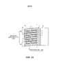
Фиг.1 представляет собой вид в разрезе, выполненном в меридиональном направлении шины, иллюстрирующий пневматическую шину в соответствии с одним вариантом осуществления настоящего изобретения.1 is a sectional view taken in the meridional direction of a tire, illustrating a pneumatic tire in accordance with one embodiment of the present invention.
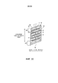
Фиг.2 представляет собой вид в плане, иллюстрирующий поверхность протектора пневматической шины, проиллюстрированной на фиг.1.FIG. 2 is a plan view illustrating a tread surface of a pneumatic tire illustrated in FIG.
Фиг.3 представляет собой разъясняющие схематическое изображение, иллюстрирующее контактный участок пневматической шины, проиллюстрированной на фиг.2.FIG. 3 is an explanatory diagram illustrating a contact portion of a pneumatic tire illustrated in FIG. 2.
Фиг.4 представляет собой увеличенный вид, иллюстрирующий основную часть блока, проиллюстрированного на фиг.3.Fig. 4 is an enlarged view illustrating the main part of the block illustrated in Fig. 3.
Фиг.5 представляет собой вид в разрезе пятна контакта блока, проиллюстрированного на фиг.4, при этом разрез выполнен по линии А-А.Figure 5 is a sectional view of the contact patch of the block illustrated in Figure 4, wherein the section is taken along line AA.
Фиг.6 представляет собой разъясняющие схематическое изображение, иллюстрирующее контактный участок пневматической шины, проиллюстрированной на фиг.2.FIG. 6 is an explanatory diagram illustrating a contact portion of a pneumatic tire illustrated in FIG. 2.
Фиг.7 представляет собой разъясняющие схематическое изображение, иллюстрирующее контактный участок пневматической шины, проиллюстрированной на фиг.2.FIG. 7 is an explanatory diagram illustrating a contact portion of a pneumatic tire illustrated in FIG.
Фиг.8 представляет собой разъясняющее схематическое изображение, иллюстрирующее модифицированный пример пневматической шины, проиллюстрированной на фиг.4.Fig. 8 is an explanatory diagram illustrating a modified example of the pneumatic tire illustrated in Fig. 4.
Фиг.9 представляет собой разъясняющее схематическое изображение, иллюстрирующее модифицированный пример пневматической шины, проиллюстрированной на фиг.4.Fig. 9 is an explanatory diagram illustrating a modified example of the pneumatic tire illustrated in Fig. 4.
Фиг.10 представляет собой разъясняющее схематическое изображение, иллюстрирующее модифицированный пример пневматической шины, проиллюстрированной на фиг.4.FIG. 10 is an explanatory diagram illustrating a modified example of a pneumatic tire illustrated in FIG.
Фиг.11 представляет собой разъясняющее схематическое изображение, иллюстрирующее модифицированный пример пневматической шины, проиллюстрированной на фиг.4.11 is an explanatory diagram illustrating a modified example of a pneumatic tire illustrated in FIG. 4.
Фиг.12 представляет собой разъясняющее схематическое изображение, иллюстрирующее модифицированный пример пневматической шины, проиллюстрированной на фиг.4.FIG. 12 is an explanatory diagram illustrating a modified example of a pneumatic tire illustrated in FIG.
Фиг.13 представляет собой разъясняющее схематическое изображение, иллюстрирующее модифицированный пример пневматической шины, проиллюстрированной на фиг.4.FIG. 13 is an explanatory diagram illustrating a modified example of the pneumatic tire illustrated in FIG.
Фиг.14 представляет собой разъясняющее схематическое изображение, иллюстрирующее модифицированный пример пневматической шины, проиллюстрированной на фиг.4.Fig. 14 is an explanatory diagram illustrating a modified example of the pneumatic tire illustrated in Fig. 4.
Фиг.15 представляет собой разъясняющее схематическое изображение, иллюстрирующее модифицированный пример пневматической шины, проиллюстрированной на фиг.4.Fig. 15 is an explanatory diagram illustrating a modified example of the pneumatic tire illustrated in Fig. 4.
Фиг.16 представляет собой разъясняющее схематическое изображение, иллюстрирующее модифицированный пример пневматической шины, проиллюстрированной на фиг.4.Fig. 16 is an explanatory diagram illustrating a modified example of the pneumatic tire illustrated in Fig. 4.
Фиг.17 представляет собой разъясняющее схематическое изображение, иллюстрирующее модифицированный пример пневматической шины, проиллюстрированной на фиг.5.FIG. 17 is an explanatory diagram illustrating a modified example of the pneumatic tire illustrated in FIG.
Фиг.18 представляет собой разъясняющее схематическое изображение, иллюстрирующее модифицированный пример пневматической шины, проиллюстрированной на фиг.4.Fig. 18 is an explanatory diagram illustrating a modified example of the pneumatic tire illustrated in Fig. 4.
Фиг.19 представляет собой разъясняющее схематическое изображение, иллюстрирующее модифицированный пример пневматической шины, проиллюстрированной на фиг.4.Fig. 19 is an explanatory diagram illustrating a modified example of the pneumatic tire illustrated in Fig. 4.
Фиг.20 представляет собой разъясняющее схематическое изображение, иллюстрирующее модифицированный пример пневматической шины, проиллюстрированной на фиг.4.FIG. 20 is an explanatory diagram illustrating a modified example of the pneumatic tire illustrated in FIG.
Фиг.21 представляет собой разъясняющее схематическое изображение, иллюстрирующее модифицированный пример пневматической шины, проиллюстрированной на фиг.4.FIG. 21 is an explanatory diagram illustrating a modified example of the pneumatic tire illustrated in FIG.
Фиг.22 представляет собой разъясняющее схематическое изображение, иллюстрирующее модифицированный пример пневматической шины, проиллюстрированной на фиг.2.FIG. 22 is an explanatory diagram illustrating a modified example of the pneumatic tire illustrated in FIG.
Фиг.23 представляет собой разъясняющее схематическое изображение, иллюстрирующее модифицированный пример пневматической шины, проиллюстрированной на фиг.2.FIG. 23 is an explanatory diagram illustrating a modified example of the pneumatic tire illustrated in FIG.
Фиг.24 представляет собой разъясняющее схематическое изображение, иллюстрирующее модифицированный пример пневматической шины, проиллюстрированной на фиг.2.FIG. 24 is an explanatory diagram illustrating a modified example of the pneumatic tire illustrated in FIG.
Фиг.25 представляет собой разъясняющее схематическое изображение, иллюстрирующее модифицированный пример пневматической шины, проиллюстрированной на фиг.2.FIG. 25 is an explanatory diagram illustrating a modified example of the pneumatic tire illustrated in FIG.
Фиг.26 представляет собой разъясняющее схематическое изображение, иллюстрирующее контактный участок пневматической шины, проиллюстрированной на фиг.25.FIG. 26 is an explanatory diagram illustrating a contact portion of a pneumatic tire illustrated in FIG. 25.
Фиг.27 представляет собой разъясняющее схематическое изображение, иллюстрирующее контактный участок пневматической шины, проиллюстрированной на фиг.25.Fig. 27 is an explanatory diagram illustrating a contact portion of the pneumatic tire illustrated in Fig. 25.
Фиг.28 представляет собой разъясняющее схематическое изображение, иллюстрирующее контактный участок пневматической шины, проиллюстрированной на фиг.25.Fig. 28 is an explanatory diagram illustrating a contact portion of the pneumatic tire illustrated in Fig. 25.
Фиг.29 представляет собой разъясняющее схематическое изображение, иллюстрирующее модифицированный пример пневматической шины, проиллюстрированной на фиг.25.Fig. 29 is an explanatory diagram illustrating a modified example of the pneumatic tire illustrated in Fig. 25.
Фиг.30 представляет собой разъясняющее схематическое изображение, иллюстрирующее модифицированный пример пневматической шины, проиллюстрированной на фиг.25.Fig. 30 is an explanatory diagram illustrating a modified example of the pneumatic tire illustrated in Fig. 25.
Фиг.31 представляет собой разъясняющее схематическое изображение, иллюстрирующее модифицированный пример пневматической шины, проиллюстрированной на фиг.25.Fig. 31 is an explanatory diagram illustrating a modified example of the pneumatic tire illustrated in Fig. 25.
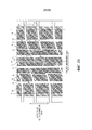
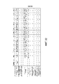
Фиг.32 представляет собой таблицу, показывающую результаты испытаний для определения эксплуатационных характеристик пневматических шин в соответствии с вариантами осуществления настоящего изобретения.32 is a table showing test results for determining the performance of pneumatic tires in accordance with embodiments of the present invention.
Фиг.33 представляет собой таблицу, показывающую результаты испытаний для определения эксплуатационных характеристик пневматических шин в соответствии с вариантами осуществления настоящего изобретения.33 is a table showing test results for determining the performance of pneumatic tires in accordance with embodiments of the present invention.
Описание вариантов осуществления изобретенияDescription of Embodiments
Варианты осуществления настоящего изобретения подробно описаны ниже со ссылкой на чертежи. Тем не менее, настоящее изобретение не ограничено данными вариантами осуществления. Кроме того, компоненты вариантов осуществления включают элементы, которые являются заменяемыми при одновременном сохранении соответствия изобретению, и очевидно заменяемые элементы. Кроме того, модифицированные примеры, описанные в вариантах осуществления, могут быть скомбинированы по желанию в пределах объема очевидности для специалистов в данной области техники.Embodiments of the present invention are described in detail below with reference to the drawings. However, the present invention is not limited to these embodiments. In addition, components of embodiments include elements that are interchangeable while maintaining compliance with the invention, and obviously interchangeable elements. In addition, the modified examples described in the embodiments may be combined as desired within the scope of obviousness to those skilled in the art.
Пневматическая шинаPneumatic tire
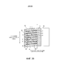
Фиг.1 представляет собой вид в разрезе, выполненном в меридиональном направлении шины, который иллюстрирует пневматическую шину в соответствии с одним вариантом осуществления настоящего изобретения. Тот же самый чертеж представляет собой вид в разрезе, иллюстрирующий зону с одной стороны в радиальном направлении шины. Кроме того, тот же самый чертеж иллюстрирует радиальную шину для пассажирского транспортного средства в качестве примера пневматической шины.1 is a cross-sectional view taken in the meridional direction of a tire that illustrates a pneumatic tire in accordance with one embodiment of the present invention. The same drawing is a sectional view illustrating an area on one side in the radial direction of the tire. In addition, the same drawing illustrates a radial tire for a passenger vehicle as an example of a pneumatic tire.
При ссылке на тот же самый чертеж «разрез/сечение в меридиональном направлении шины» относится к сечению шины, выполненному вдоль плоскости, которая включает в себя ось вращения шины (непроиллюстрированную). Ссылочная позиция CL обозначает экваториальную плоскость шины и относится к плоскости, нормальной к оси вращения шины, которая проходит через точку шины, центральную в направлении оси вращения шины. Термин «боковое направление шины» относится к направлению, параллельному оси вращения шины. Термин «радиальное направление шины» относится к направлению, перпендикулярному к оси вращения шины.When referring to the same drawing, “section / section in the meridional direction of the tire” refers to a section of a tire made along a plane that includes the axis of rotation of the tire (not illustrated). The reference position CL denotes the equatorial plane of the tire and refers to a plane normal to the axis of rotation of the tire, which passes through the point of the tire, central in the direction of the axis of rotation of the tire. The term "lateral tire direction" refers to a direction parallel to the axis of rotation of the tire. The term "radial tire direction" refers to a direction perpendicular to the axis of rotation of the tire.
Пневматическая шина 1 имеет кольцевую конструкцию с осью вращения шины в качестве ее центра и включает в себя два сердечника 11, 11 бортов, два наполнительных шнура 12, 12 бортов, слой 13 каркаса, брекерный слой 14, резиновый протектор 15, две резиновые боковины 16, 16 и два амортизирующих резиновых элемента 17, 17 для обода (см. фиг.1).The pneumatic tire 1 has a ring structure with the axis of rotation of the tire as its center and includes two
Два сердечника 11, 11 бортов представляют собой кольцевые элементы, образованные множеством бортовых проволок, связанных вместе в пучок. Два сердечника 11, 11 бортов образуют сердечники левой и правой бортовых частей. Два наполнительных шнура 12, 12 бортов расположены на перифериях двух сердечников 11, 11 бортов в радиальном направлении шины и образуют бортовые части.Two
Слой 13 каркаса имеет однослойную структуру, образованную одним слоем каркаса, или многослойную структуру, образованную наложенными друг на друга слоями каркаса, и проходит между левым и правым сердечниками 11, 11 бортов в виде тороида, образуя каркас для шины. Кроме того, обе концевые части слоя 13 каркаса загнуты наружу в боковом направлении шины так, чтобы они охватывали сердечники 11 бортов и наполнительные шнуры 12 бортов, и зафиксированы. Слой (слои) каркаса в слое 13 каркаса образован (-ы) посредством множества кордов каркаса, образованных из стали или из материала из органических волокон (например, арамидных, нейлоновых, полиэфирных, вискозных или тому подобных), покрытых резиновым покрытием и подвергнутых процессу прикатки. Слой (слои) каркаса имеет (имеют) угол каркаса (угол наклона направления волокон кордов каркаса относительно направления вдоль окружности шины), абсолютная величина которого составляет от 80 градусов до 95 градусов.The carcass ply 13 has a single layer structure formed by a single carcass ply or a multilayer structure formed by superimposed carcass ply layers and extends between the left and
Брекерный слой 14 образован наложением друг на друга двух перекрещивающихся брекеров 141, 142 и закрывающего брекера 143 и расположен вокруг периферии слоя 13 каркаса. Два перекрещивающихся брекера 141, 142 образованы множеством кордов брекера, образованных из стали или из материала из органических волокон, покрытых резиновым покрытием и подвергнутых процессу прикатки. Перекрещивающиеся брекеры 141, 142 имеют угол брекера, абсолютная величина которого составляет от 20 градусов до 55 градусов. Кроме того, два перекрещивающихся брекера 141, 142 имеют углы брекера (угол наклона направления волокон кордов брекера относительно направления вдоль окружности шины), имеющие противоположные знаки, и брекеры наложены друг на друга так, что направления волокон кордов брекера пересекаются друг с другом (конфигурация с перекрещивающимися слоями). Закрывающий брекер 143 образован множеством кордов, образованных из стали или из материала из органических волокон, покрытых резиновым покрытием и подвергнутых процессу прикатки. Закрывающий брекер 143 имеет угол брекера, абсолютная величина которого составляет от 0 до 10 градусов. Закрывающий брекер 143 размещен при его наложении снаружи по отношению к перекрещивающимся брекерам 141, 142 в радиальном направлении шины.The
Резиновый протектор 15 расположен снаружи слоя 13 каркаса и брекерного слоя 14 в радиальном направлении шины и образует протекторную часть. Две резиновые боковины 16, 16 расположены снаружи слоя 13 каркаса в боковом направлении шины и образуют части, представляющие собой левую и правую боковины. Два амортизирующих резиновых элемента 17, 17 для обода расположены внутри по отношению к левому и правому сердечникам 11, 11 бортов и загнутым частям слоя 13 каркаса в радиальном направлении шины. Два амортизирующих резиновых элемента 17, 17 для обода образуют поверхности контакта левой и правой бортовых частей с бортами обода.The
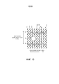
Рисунок протектораTread pattern
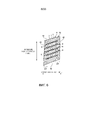
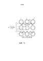
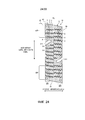
Фиг.2 представляет собой вид в плане, иллюстрирующий поверхность протектора пневматической шины, проиллюстрированной на фиг.1. Тот же самый чертеж иллюстрирует рисунок протектора нешипованной шины. При ссылке на тот же самый чертеж «направление вдоль окружности шины» относится к направлению вращения/поворота вокруг оси вращения шины. Ссылочная позиция Т обозначает край зоны контакта шины с грунтом.FIG. 2 is a plan view illustrating a tread surface of a pneumatic tire illustrated in FIG. The same drawing illustrates the tread pattern of a studless tire. When referring to the same drawing, “tire circumferential direction” refers to the direction of rotation / rotation about the axis of rotation of the tire. The reference position T denotes the edge of the contact zone of the tire with the ground.
Как проиллюстрировано на фиг.2, пневматическая шина 1 в протекторной части выполнена с множеством окружных основных канавок 21, 22, проходящих в направлении вдоль окружности шины, множеством контактных участков 31-33, границы которых определяются окружными основными канавками 21, 22, и множеством поперечных боковых канавок 41-43, расположенных на контактных участках 31-33.As illustrated in FIG. 2, the pneumatic tire 1 in the tread portion is provided with a plurality of circumferential
Термин «окружная основная канавка» относится к окружной канавке, которая имеет указатель износа, который указывает на терминальную стадию износа, и, как правило, имеет ширину канавки, составляющую 5,0 мм или более, и глубину канавки, составляющую 7,5 мм или более. Кроме того, термин «поперечная боковая канавка» относится к поперечной канавке, имеющей ширину канавки, составляющую 2,0 мм или более, и глубину канавки, составляющую 3,0 мм или более.The term “circumferential main groove” refers to a circumferential groove that has a wear indicator that indicates a terminal wear stage, and typically has a groove width of 5.0 mm or more and a groove depth of 7.5 mm or more. In addition, the term "lateral lateral groove" refers to a transverse groove having a groove width of 2.0 mm or more and a groove depth of 3.0 mm or more.
Ширина канавки представляет собой максимальное расстояние между левой и правой стенками канавки во входной части канавки, и ширину канавки измеряют, когда шина смонтирована на заданном ободе, накачана до заданного внутреннего давления и находится в ненагруженном состоянии. В конфигурациях, в которых контактные участки включают в себя части с вырезом/вырезанные части или скошенные части на их краевых частях, ширину канавки измеряют относительно точек, в которых пятно контакта протектора и линии продолжения стенок канавки пересекаются, если смотреть в сечении, нормальном к направлению длины канавки. Кроме того, в конфигурации, в которой канавки проходят с зигзагообразной формой или с волнообразной формой в направлении вдоль окружности шины, ширину канавки измеряют относительно центральной линии максимального интервала между стенками канавки.The width of the groove is the maximum distance between the left and right walls of the groove in the inlet of the groove, and the width of the groove is measured when the tire is mounted on a given rim, inflated to a given internal pressure and is in an unloaded state. In configurations in which the contact portions include cut-out / cut-out parts or beveled parts at their edge parts, the width of the groove is measured relative to the points at which the contact patch of the tread and the extension line of the walls of the groove intersect when viewed in a section normal to the direction groove lengths. Furthermore, in a configuration in which the grooves extend in a zigzag shape or in a wave shape in the direction along the circumference of the tire, the width of the groove is measured relative to the center line of the maximum interval between the walls of the groove.
Глубина канавки представляет собой максимальное расстояние от пятна контакта протектора до дна канавки, и глубину канавки измеряют, когда шина смонтирована на заданном ободе, накачана до заданного внутреннего давления и находится в ненагруженном состоянии. Кроме того, в конфигурациях, в которых канавки включают в себя неровный участок или щелевидные дренажные канавки на дне канавки, глубину канавки измеряют, не принимая во внимание данные участки.The groove depth is the maximum distance from the tread contact spot to the bottom of the groove, and the groove depth is measured when the tire is mounted on a given rim, inflated to a predetermined internal pressure and is in an unloaded state. In addition, in configurations in which the grooves include an uneven portion or slit-like drainage grooves at the bottom of the groove, the depth of the groove is measured without regard to these portions.
Термин «заданный обод» относится к «применимому ободу», определенному Ассоциацией производителей автомобильных шин Японии (JATMA), «Расчетному ободу», определенному Ассоциацией по шинам и ободьям (TRA), или «Мерному колесу», определенному Европейской технической организацией по шинам и ободьям (ETRTO). Кроме того, «заданное внутреннее давление» относится к «максимальному давлению воздуха», определяемому JATMA, к максимальной величине в «ПРЕДЕЛЬНЫХ НАГРУЗКАХ ШИНЫ ПРИ РАЗЛИЧНЫХ ДАВЛЕНИЯХ НАКАЧИВАНИЯ В ХОЛОДНОЕ ВРЕМЯ», определяемых TRA, и к «ДАВЛЕНИЯМ НАКАЧИВАНИЯ», определяемым ETRTO. Кроме того, «заданная нагрузка» относится к «максимальной нагрузочной способности», определяемой JATMA, максимальной величине в «ПРЕДЕЛЬНЫХ НАГРУЗКАХ ШИНЫ ПРИ РАЗЛИЧНЫХ ДАВЛЕНИЯХ НАКАЧИВАНИЯ В ХОЛОДНОЕ ВРЕМЯ», определяемых TRA, и к «НАГРУЗОЧНОЙ СПОСОБНОСТИ», определяемой ETRTO. Тем не менее, согласно JATMA в случае шины для пассажирских транспортных средств заданное внутреннее давление представляет собой давление воздуха, составляющее 180 кПа, и заданная нагрузка составляет 88% от максимальной нагрузочной способности.The term “defined rim” refers to the “applicable rim” defined by the Japan Automobile Tire Manufacturers Association (JATMA), the “Designed Rim” defined by the Tire and Rim Association (TRA), or the “Measuring Wheel” defined by the European Tire and rims (ETRTO). In addition, “set internal pressure” refers to the “maximum air pressure” defined by JATMA, to the maximum value in “TIRE LOAD LIMITS AT DIFFERENT COLD PRESSURE PRESSURES” defined by TRA, and to the “PUMP PRESSURE” defined by ETRTO. In addition, “target load” refers to the “maximum load capacity” defined by JATMA, the maximum value in the “LIMIT TIRE LOADS AT DIFFERENT INFORMATION PERFORMANCE IN COLD TIME” defined by TRA, and the “LOAD CAPABILITY” defined by ETRTO. However, according to JATMA, in the case of a passenger vehicle tire, the predetermined internal pressure is an air pressure of 180 kPa, and the predetermined load is 88% of the maximum load capacity.
Например, в конфигурации по фиг.2 четыре окружные основные канавки 21, 22, имеющие прямолинейную форму, расположены с лево-правой симметрией относительно экваториальной плоскости CL шины. Кроме того, границы пяти контактных участков 31-33 определяются четырьмя окружными основными канавками 21, 22. Контактный участок 31 расположен на экваториальной плоскости CL шины. Контактные участки 31-33 включают в себя множество поперечных боковых канавок 41-43, которые расположены с заданными интервалами в направлении вдоль окружности шины и которые проходят через контактные участки 31-33 в боковом направлении шины. Каждый из вторых контактных участков 32 выполнен с окружной узкой канавкой 23, которая проходит с изгибами в направлении вдоль окружности шины. Каждый из контактных участков 31-33 образован в виде ряда блоков, границы которых определяются окружными основными канавками 21, 22, окружными узкими канавками 23 и поперечными боковыми канавками 41-43.For example, in the configuration of FIG. 2, four circumferential
Следует отметить, что в конфигурации по фиг.2, подобной описанной выше, окружные основные канавки 21, 22 имеют прямолинейную форму. Тем не менее, настоящее изобретение не ограничено подобной конфигурацией, и окружные основные канавки 21, 22 могут иметь зигзагообразную форму или волнообразную форму с изгибами или криволинейностью, когда они проходят в направлении вдоль окружности шины (не проиллюстрировано).It should be noted that in the configuration of FIG. 2, similar to that described above, the circumferential
В конфигурации по фиг.2, подобной описанной выше, контактные участки 31-33 разделены в направлении вдоль окружности шины поперечными боковыми канавками 41-43, и при этом образуются ряды блоков. Тем не менее, настоящее изобретение не ограничено подобной конфигурацией, и, например, поперечные боковые канавки 41-43 могут иметь полузакрытую конструкцию, при которой поперечные боковые канавки 41-43 заканчиваются в пределах контактных участков 31-33, в результате чего контактные участки 31-33 образуются в виде ребер, непрерывных в направлении вдоль окружности шины (не проиллюстрировано).In the configuration of FIG. 2, similar to that described above, the contact sections 31-33 are divided in the direction along the tire circumference by the lateral lateral grooves 41-43, and rows of blocks are formed. However, the present invention is not limited to such a configuration, and, for example, the transverse side grooves 41-43 may have a half-closed structure in which the transverse side grooves 41-43 end within the contact sections 31-33, resulting in the contact sections 31- 33 are formed as ribs continuous in the tire circumferential direction (not illustrated).
В конфигурации по фиг.2 пневматическая шина 1 имеет рисунок протектора с лево-правой симметрией. Тем не менее, настоящее изобретение не ограничено подобной конфигурацией, и, например, рисунок протектора может иметь лево-правую осевую симметрию, лево-правую асимметрию или направленность в направлении вращения шины (не проиллюстрировано).In the configuration of FIG. 2, the pneumatic tire 1 has a tread pattern with left-right symmetry. However, the present invention is not limited to such a configuration, and, for example, the tread pattern may have left-right axial symmetry, left-right asymmetry or directionality in the direction of rotation of the tire (not illustrated).
В конфигурации по фиг.2 пневматическая шина 1 выполнена с окружными основными канавками 21, 22, которые проходят в направлении вдоль окружности шины. Тем не менее, настоящее изобретение не ограничено подобной конфигурацией, и вместо окружных основных канавок 21, 22 пневматическая шина 1 может быть выполнена с множеством наклонных основных канавок, которые проходят с наклоном под заданным углом относительно направления вдоль окружности шины. Например, пневматическая шина 1 может быть выполнена с множеством V-образных наклонных основных канавок, которые имеют V-образную конфигурацию с выступом, проходящим в направлении вдоль окружности шины, и проходят в боковом направлении шины, открываясь на левом и правом краях протектора, с множеством поперечных боковых канавок, которые соединяют соседние V-образные наклонные основные канавки, и с множеством контактных участков, границы которых определяются V-образными наклонными основными канавками и поперечными боковыми канавками (не проиллюстрировано).In the configuration of FIG. 2, the pneumatic tire 1 is formed with circumferential
Щелевидные дренажные канавки блокаSlit-like drainage grooves of the block
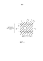
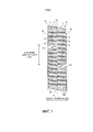
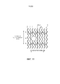
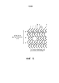
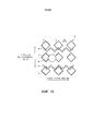
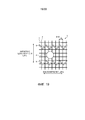
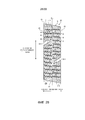
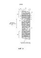
Фиг.3 представляет собой разъясняющие схематическое изображение, иллюстрирующее контактный участок пневматической шины, проиллюстрированной на фиг.2. Фиг.3 представляет собой вид в плане одного блока 5, который образует контактный участок 33 плечевой зоны.FIG. 3 is an explanatory diagram illustrating a contact portion of a pneumatic tire illustrated in FIG. 2. Figure 3 is a plan view of one
Как проиллюстрировано на фиг.2 и 3, в пневматической шине 1 блоки 5 контактных участков 31-33 включают в себя множество щелевидных дренажных канавок 6. При выполнении щелевидных дренажных канавок 6 краевые компоненты контактных участков 31-33 увеличиваются, и улучшаются эксплуатационные характеристики шины при движения по снегу и льду.As illustrated in FIGS. 2 and 3, in the pneumatic tire 1, the
Подобная щелевидная дренажная канавка представляет собой прорезь, образованную на контактном участке, которая, как правило, имеет ширину щелевидной дренажной канавки, составляющую менее 1,0 мм, и глубину щелевидной дренажной канавки, составляющую 2,0 мм или более, и закрывается, когда шина входит в контакт с грунтом. Следует отметить, что максимальное значение глубины щелевидной дренажной канавки не ограничено особым образом, но оно, как правило, меньше глубины канавок, представляющих собой основные канавки.Such a slit-like drainage groove is a slot formed in the contact portion, which typically has a slot-like drainage groove width of less than 1.0 mm and a slot-like drainage groove of 2.0 mm or more, and closes when the tire comes in contact with the ground. It should be noted that the maximum depth of the slit-like drainage groove is not particularly limited, but it is usually less than the depth of the grooves, which are the main grooves.
Ширина щелевидной дренажной канавки представляет собой максимальное расстояние, соответствующее ширине раскрыва щелевидной дренажной канавки в пятне контакта контактного участка, и ширину щелевидной дренажной канавки измеряют, когда шина смонтирована на заданном ободе, накачана до заданного внутреннего давления и находится в ненагруженном состоянии.The width of the slit-like drainage groove is the maximum distance corresponding to the opening width of the slit-like drainage groove in the contact patch of the contact portion, and the width of the slit-like drainage groove is measured when the tire is mounted on a given rim, inflated to a predetermined internal pressure and is in an unloaded state.
Следует отметить, что щелевидные дренажные канавки 6 могут иметь закрытую конструкцию, при которой щелевидные дренажные канавки 6 заканчиваются в пределах контактных участков 31-33 в обеих концевых частях, полузакрытую конструкцию, при которой щелевидные дренажные канавки 6 открыты в краевой части блока 5 в одной концевой части и заканчиваются в пределах блока 5 в другой концевой части, или открытую конструкцию, при которой щелевидные дренажные канавки 6 открыты в краевых частях блока 5 в обеих концевых частях. Кроме того, длина, число и схема расположения щелевидных дренажных канавок 6 на контактных участках 31-33 могут быть выбраны соответствующим образом в пределах объема очевидности для специалистов в данной области техники. Щелевидные дренажные канавки 6 могут проходить в боковом направлении шины, в направлении вдоль окружности шины или в любом направлении, имеющем наклон относительно данных направлений.It should be noted that the slit-
Например, в конфигурации по фиг.3 контактный участок 33 плечевой зоны включает в себя множество блоков 5, границы которых определяются самой дальней от центра, окружной основной канавкой 22 и множеством поперечных боковых канавок 43 (см. фиг.2). Каждый из блоков 5 включает в себя множество щелевидных дренажных канавок 6. Кроме того, щелевидные дренажные канавки 6, имеющие зигзагообразную форму, проходят в боковом направлении шины и расположены рядом друг с другом с заданными интервалами в направлении вдоль окружности шины. Кроме того, щелевидные дренажные канавки 6, самые дальние от центра в направлении вдоль окружности шины, имеют закрытую конструкцию, при которой щелевидные дренажные канавки 6 заканчиваются в пределах блока 5 в обеих концевых частях. В результате обеспечивается жесткость краевых частей переднего края и заднего края блока 5 при качении шины. Щелевидные дренажные канавки 6 в части, центральной в направлении вдоль окружности шины, имеют полузакрытую конструкцию, при которой щелевидные дренажные канавки 6 открываются в окружную основную канавку 22 в одной концевой части и заканчиваются в пределах блока 5 в другой концевой части. В результате жесткость блока 5 в центральной части уменьшается, и обеспечивается равномерное распределение жесткости блоков в направлении вдоль окружности шины.For example, in the configuration of FIG. 3, the
Узкая неглубокая канавка блокаNarrow shallow block groove
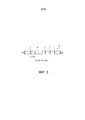
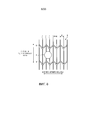
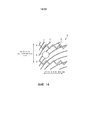
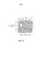
Фиг.4 представляет собой увеличенный вид, иллюстрирующий основную часть блока, проиллюстрированного на фиг.3. Фиг.5 представляет собой вид в разрезе пятна контакта блока, проиллюстрированного на фиг.4, при этом разрез выполнен по линии А-А. Фиг.4 иллюстрирует взаимное расположение щелевидных дренажных канавок 6, узких неглубоких канавок 7 и углубления 8. Фиг.5 представляет собой вид в разрезе в направлении глубины узких неглубоких канавок 7 и углубления 8.Fig. 4 is an enlarged view illustrating the main part of the block illustrated in Fig. 3. Figure 5 is a sectional view of the contact patch of the block illustrated in Figure 4, wherein the section is taken along line AA. Figure 4 illustrates the relative position of the slit-
В пневматической шине 1 контактные участки 31-33 включают в себя множество узких неглубоких канавок 7 в пятне контакта (см. фиг.3). При такой конфигурации за счет того, что узкие неглубокие канавки 7 «впитывают» и удаляют водяную пленку, образующуюся между поверхностью обледеневшей дороги и поверхностью протектора при входе шины в контакт с грунтом, тормозная характеристика шины при движении по льду улучшается.In the pneumatic tire 1, the contact sections 31-33 include a plurality of narrow
Узкие неглубокие канавки 7 имеют ширину канавок, составляющую от 0,2 мм до 0,7 мм, и глубину Hg канавок, составляющую от 0,2 мм до 0,7 мм (см. фиг.5). Таким образом, узкие неглубокие канавки 7 имеют меньшую глубину, чем щелевидные дренажные канавки 6. Кроме того, узкие неглубокие канавки 7 расположены от края до края всей поверхности контактных участков 31-33.The narrow
Например, в конфигурации по фиг.3 узкие неглубокие канавки 7 расположены во всей зоне пятна контакта контактного участка 33 плечевой зоны. Узкие неглубокие канавки 7 имеют прямолинейную форму и расположены с наклоном под заданным углом θ наклона относительно направления вдоль окружности шины (см. фиг.4). Узкие неглубокие канавки 7 расположены рядом друг с другом с заданными шагами Р(см. фиг.4). Как проиллюстрировано на фиг.4, узкие неглубокие канавки 7 пересекают щелевидные дренажные канавки 6 и разделены щелевидными дренажными канавками 6 в продольном направлении.For example, in the configuration of FIG. 3, narrow
Следует отметить, что, как проиллюстрировано на фиг.3, в конфигурации, в которой узкие неглубокие канавки 7 являются удлиненными и расположены рядом друг с другом, водяная пленка, поглощаемая узкими неглубокими канавками 7, направляется через узкие неглубокие канавки 7 в продольном направлении и отводится. В подобной конфигурации угол θ наклона узких неглубоких канавок 7 (см. фиг.4) предпочтительно находится в диапазоне 20 градусов≤θ≤80 градусов и более предпочтительно - в диапазоне 40 градусов≤θ≤60 градусов. Шаг Р расположения (см. фиг.4) узких неглубоких канавок 7 предпочтительно находится в диапазоне 0,5 мм≤Р≤1,5 мм и более предпочтительно - в диапазоне 0,7 мм≤Р≤1,2 мм. В результате соответствующим образом обеспечивается функциональная способность узких неглубоких канавок 7 удалять водяную пленку, и обеспечивается площадь контакта контактных участков 31-33 с грунтом. Следует отметить, что плотность расположения узких неглубоких канавок 7 не ограничена особым образом, но шаг Р расположения, описанный выше, накладывает ограничения на нее.It should be noted that, as illustrated in FIG. 3, in a configuration in which the narrow
Шаг Р расположения узких неглубоких канавок 7 определяется как расстояние между осевыми линиями канавок, представляющих собой соседние узкие неглубокие канавки 7, 7.The step P of the location of the narrow
Углубления блокаBlock recesses
Как проиллюстрировано на фиг.2 и 3, в пневматической шине 1 каждый из контактных участков 31-33 включает в себя множество углублений 8 в пятне контакта. При такой конфигурации за счет того, что углубления 8 «впитывают» водяную пленку, образующуюся между поверхностью обледеневшей дороги и поверхностью протектора при контакте шины с грунтом, и краевые компоненты контактных участков 31-33 увеличиваются при выполнении углублений 8, тормозная характеристика шины при движении по льду улучшается.As illustrated in FIGS. 2 and 3, in the pneumatic tire 1, each of the contact sections 31-33 includes a plurality of
Каждое из углублений 8 представляет собой замкнутое углубление (углубление или впадину, которое (-ая) не открывается на границе пятна контакта), образованное в пятне контакта контактных участков 31-33. Углубление 8 имеет произвольно выбранную геометрическую форму в пятне контакта контактных участков 31-33. Например, форма углубления 8 может быть круглой, эллиптической, четырехугольной или другой многоугольной формой. Круглое или эллиптическое углубление 8 является предпочтительным для уменьшения неравномерного износа зоны пятна контакта контактных участков 31-33, и многоугольное углубление 8 является предпочтительным для улучшения тормозной характеристики при движении по льду за счет увеличенных краевых компонентов.Each of the
Кроме того, площадь проема углубления 8 предпочтительно находится в диапазоне от 2,5 мм2 до 10 мм2. Например, круглое углубление 8 имеет диаметр, находящийся в диапазоне от приблизительно 1,8 мм до 3,6 мм. В результате обеспечивается функциональная способность углубления 8 удалять водяную пленку.In addition, the opening area of the
Площадь проема углубления 8 представляет собой площадь проема углубления 8 в пятне контакта контактных участков 31-33, и данную площадь измеряют, когда шина смонтирована на заданном ободе, накачана до заданного внутреннего давления и находится в ненагруженном состоянии.The opening area of the
Кроме того, глубина Hd (см. фиг.5) углубления 8 и глубина Hg канавки, представляющей собой узкую неглубокую канавку 7, предпочтительно имеют соотношение 0,5≤Hd/Hg≤1,5 и более предпочтительно имеют соотношение 0,8≤Hd/Hg≤1,2. Другими словами, глубина Hd углубления 8 приблизительно равна глубине Hg канавки, представляющей собой узкую неглубокую канавку 7. В результате улучшается функциональная способность зоны пятна контакта контактных участков 31-33 поглощать воду. Кроме того, за счет того, что углубление 8 имеет малую глубину по сравнению с щелевидными дренажными канавками (например, с прямолинейной щелевидной дренажной канавкой 6 или круговой щелевидной дренажной канавкой (непроиллюстрированной)), жесткость контактных участков 31-33 обеспечивается надлежащим образом. Таким образом, обеспечиваются тормозная характеристика шины при движении по льду.In addition, the depth Hd (see FIG. 5) of the
Кроме того, угол α наклона стенки (см. фиг.5) углубления 8 предпочтительно находится в диапазоне -85 градусов≤α≤95 градусов. Другими словами, внутренняя стенка углубления 8 предпочтительно является по существу вертикальной относительно пятна контакта контактных участков 31-33. В результате краевые компоненты углубления 8 увеличиваются.In addition, the angle α of the wall (see FIG. 5) of the
Угол α наклона стенки углубления 8 представляет собой угол, образованный пятном контакта контактных участков 31-33 и внутренней стенкой углубления 8, если смотреть в сечении углубления 8, выполненном в направлении глубины.The angle α of inclination of the wall of the
Кроме того, как проиллюстрировано на фиг.4, углубление 8 расположено на расстоянии от щелевидных дренажных канавок 6. Другими словами, углубления 8 и щелевидные дренажные канавки 6 расположены в разных местах в пятне контакта контактных участков 31-33 и не пересекаются. Расстояние g между углублением 8 и щелевидными дренажными канавками 6 предпочтительно находится в диапазоне 0,2 мм≤g и более предпочтительно - в диапазоне 0,3 мм≤g. В результате жесткость контактных участков 31-33 обеспечивается соответствующими образом.In addition, as illustrated in FIG. 4, the
Кроме того, как проиллюстрировано на фиг.4, углубление 8 расположено так, что оно пересекается и сообщается с узкими неглубокими канавками 7. Углубление 8 расположено поперек отдельных соседних узких неглубоких канавок 7, 7. Другими словами, отдельные соседние узкие неглубокие канавки 7, 7 расположены так, что они проходят через одно углубление 8. В результате соседние узкие неглубокие канавки 7, 7 сообщаются друг с другом посредством углубления 8. Кроме того, углубление 8 расположено между соседними узкими неглубокими канавками 7, 7 и обеспечивает частичное увеличение объема узких неглубоких канавок 7. Таким образом, когда шина входит в контакт с грунтом, вода удерживается в углублении 8, и водяная пленка на поверхности контакта с дорогой эффективно поглощается. В результате улучшается тормозная характеристика шины при движении по льду.In addition, as illustrated in FIG. 4, the
Термин «отдельные узкие неглубокие канавки 7» относится к множеству узких неглубоких канавок 7, которые проходят, не пересекаясь, в схеме расположения, в которой имеются только узкие неглубокие канавки 7, не считая щелевидных дренажных канавок 6 и углублений 8. Соответственно, никакие варианты осуществления настоящего изобретения не имеют схемы расположения, в которой множество узких неглубоких канавок 7 пересекаются друг с другом.The term “individual narrow
Например, в конфигурации по фиг.3 узкие неглубокие канавки 7, имеющие прямолинейную форму, расположены на всей поверхности контактного участка 33 с заданными шагами при их одновременном наклоне под заданным углом относительно направления вдоль окружности шины. В результате, как проиллюстрировано на фиг.4, соседние узкие неглубокие канавки 7, 7 проходят рядом друг с другом в одном и том же направлении. Кроме того, углубление 8 расположено поперек двух соседних узких неглубоких канавок 7, 7 для обеспечения возможности сообщения данных двух соседних неглубоких канавок 7, 7 друг с другом. Другими словами, данные две узкие неглубокие канавки 7, 7, проходящие рядом друг с другом, проходят через одно углубление 8. Следует отметить, что настоящее изобретение не ограничено конфигурацией, описанной выше, и три или более узких неглубоких канавок 7 могут проходить через одно углубление 8 (не проиллюстрировано).For example, in the configuration of FIG. 3, narrow
Кроме того, в конфигурации, описанной выше, количество углублений 8, расположенных поперек соседних узких неглубоких канавок 7, 7 в пятне контакта одного блока 5, предпочтительно составляет 70% или более и более предпочтительно - 80% или более от общего количества углублений 8 в пятне контакта. В результате углубления 8 могут эффективно функционировать для удерживания воды, как описано выше. Например, в конфигурации по фиг.3 все углубления 8 расположены поперек двух соседних узких неглубоких канавок 7, 7. Тем не менее, настоящее изобретение не ограничено подобной конфигурацией, и одно или более из углублений 8 могут пересекаться с одной узкой неглубокой канавкой 7 или могут быть расположены между соседними узкими неглубокими канавками 7, 7 без пересечения с узкой неглубокой канавкой 7 (не проиллюстрировано).In addition, in the configuration described above, the number of
Кроме того, в конфигурации по фиг.3 контактный участок 33 выполнен с множеством щелевидных дренажных канавок 6, которые ограничивают узкие неглубокие канавки 7 в пятне контакта. Каждый участок узких неглубоких канавок 7, ограниченный щелевидными дренажными канавками 6, проходит, не проходя через множество углублений 8. Другими словами, углубления 8 расположены рассредоточенно, так что два или более углублений 8 не расположены на одном и том же участке узких неглубоких канавок 7, ограниченном щелевидными дренажными канавками 6. Соответственно, на каждом участке узких неглубоких канавок 7 расположено максимум одно углубление 8.In addition, in the configuration of FIG. 3, the
Кроме того, как проиллюстрировано на фиг.3, углубления 8 распределены более редко, чем узкие неглубокие канавки 7. Более конкретно, плотность Da расположения углублений 8 во всей зоне пятна контакта одного ребра или блока предпочтительно находится в диапазоне 0,8 единицы/см2≤Da≤4,0 единицы/см2 и более предпочтительно - в диапазоне 1,0 единицы/см2≤Da≤3,0 единицы/см2. В результате обеспечивается площадь пятна контакта контактных участков 31-33.In addition, as illustrated in FIG. 3, the
Плотность Da расположения углублений 8 определяется как общее количество углублений 8 по отношению к площади пятна контакта одного ребра или блока. Например, в конфигурации, в которой контактные участки представляют собой ребра, непрерывные в направлении вдоль окружности шины (не проиллюстрировано), общее количество углублений 8 по отношению к площади пятна контакта одного полного ребра определяется как плотность Da расположения. В альтернативном варианте в конфигурации, в которой контактные участки представляют собой блоки (см. фиг.2 и 3), общее количество углублений 8 по отношению к площади пятна контакта одного блока 5 определяется как плотность Da расположения.The density Da of the location of the
Площадь пятна контакта измеряют на поверхности контакта между шиной и плоской плитой, когда шина смонтирована на заданном ободе, накачана до заданного внутреннего давления, размещена вертикально на плоской плите в статическом состоянии и находится под действием нагрузки, которая соответствует заданной нагрузке.The area of the contact spot is measured on the contact surface between the tire and the flat plate when the tire is mounted on a given rim, inflated to a predetermined internal pressure, placed vertically on a flat plate in a static state, and is under the action of a load that corresponds to a given load.
Доля площади проемов углубленийThe proportion of the area of the openings of the recesses
В пневматической шине 1 доля Se площади проемов углублений 8 в зонах ER (см. фиг.3) частей, концевых в боковом направлении шины и определяемых в непрерывном пятне контакта, и доля Sc площади проемов углублений 8 в зоне части, центральной в боковом направлении шины, и имеют соотношение Sс < Sе. Другими словами, доля Se площади проемов углублений 8 в зонах ER (см. фиг.3) концевых частей превышает долю Sc площади проемов углублений 8 в зоне центральной части. Кроме того, доли Sc, Se площадей проемов углублений 8 предпочтительно имеют соотношение 1,50≤Sе/Sс и более предпочтительно имеют соотношение 3,00≤Sе/Sс. Максимальная величина отношения Sе/Sс не ограничена особым образом, но ее взаимосвязь, например, с плотностью расположения и площадью проемов углублений 8 накладывает ограничения на данную величину. В конфигурации, в которой все углубления 8 расположены в зонах ЕR концевых частей (см., например, конфигурацию по фиг.7, описанную ниже), значение Sс равно нулю, тем самым оно удовлетворяет условию Sс < Sе.In the pneumatic tire 1, the proportion Se of the area of the openings of the
Пятно контакта контактных участков определяется как поверхность контакта между шиной и плоской плитой, когда шина смонтирована на заданном ободе, накачана до заданного внутреннего давления, размещена вертикально на плоской плите в статическом состоянии и находится под действием нагрузки, которая соответствует заданной нагрузке.The contact patch of the contact areas is defined as the contact surface between the tire and the flat plate, when the tire is mounted on a given rim, inflated to a predetermined internal pressure, placed vertically on a flat plate in a static state, and is under the action of a load that corresponds to a given load.
Непрерывное пятно контакта определяется как пятно контакта, ограниченное канавками, имеющими ширину канавок, составляющую 2,0 мм или более, и глубину канавок, составляющую 3,0 мм или более. Более конкретно, пятно контакта одного ребра или одного блока, границы которого определяются поперечными боковыми канавками и окружными канавками, имеющими ширину канавок и глубину канавок, описанные выше, соответствует непрерывному пятну контакта, описанному выше. Кроме того, например, закрытые поперечные боковые канавки, которые заканчиваются в пределах контактных участков, вырезы, частично образованные на контактных участках (например, вырезанная часть 311 по фиг.7, описанная ниже), и щелевидные дренажные канавки и прорези, которые закрываются, когда шина входит в контакт с грунтом, не разделяют пятно контакта контактных участков и, таким образом, не соответствуют канавкам, описанным выше.A continuous contact spot is defined as a contact spot bounded by grooves having a groove width of 2.0 mm or more and a groove depth of 3.0 mm or more. More specifically, the contact spot of one rib or one block, the boundaries of which are defined by transverse lateral grooves and circumferential grooves having the width of the grooves and the depth of the grooves described above, corresponds to the continuous contact spot described above. In addition, for example, closed lateral lateral grooves that terminate within the contact portions, cutouts partially formed at the contact portions (for example, the
Зона части, центральной в боковом направлении шины, задана как зона в центральной части, занимающей 50% от непрерывного пятна контакта в боковом направлении шины (см. фиг.3). Зона части, концевой в боковом направлении шины, задана как зона левой и правой концевых частей, каждая из которых занимает 25% от непрерывного пятна контакта в боковом направлении шины. Например, в конфигурации, в которой контактные участки представляют собой ребра, непрерывные в направлении вдоль окружности шины (не проиллюстрировано), пятно контакта одного полного ребра разделено в боковом направлении шины на зону центральной части и зоны концевых частей. В альтернативном варианте в конфигурации, в которой контактные участки представляют собой ряды блоков (см. фиг.2), пятно контакта каждого блока, который образует ряд блоков, разделено на зону центральной части и зоны концевых частей. Следует отметить, что пунктирные линии на фиг.3 показывают граничные линии между зоной центральной части и зонами концевых частей.The zone of the part centrally in the lateral direction of the tire is defined as the zone in the central part occupying 50% of the continuous contact patch in the lateral direction of the tire (see FIG. 3). The area of the side lateral portion of the tire is defined as the area of the left and right end parts, each of which occupies 25% of the continuous contact patch in the lateral direction of the tire. For example, in a configuration in which the contact portions are ribs continuous in the circumferential direction of the tire (not illustrated), the contact patch of one full rib is laterally divided into the tire region of the center portion and the end portion zone. Alternatively, in a configuration in which the contact areas are rows of blocks (see FIG. 2), the contact spot of each block that forms a series of blocks is divided into a zone of the central part and a zone of end parts. It should be noted that the dashed lines in FIG. 3 show the boundary lines between the zone of the central part and the zones of the end parts.
Доля площади проемов углублений определяется как отношение между суммой площадей проемов углублений, расположенных в заданной зоне, и площадью пятна контакта той же самой зоны. В конфигурации, в которой углубление и граничная линия зоны пересекаются, углубление считается расположенным в данной зоне, если его центральная точка находится в пределах данной зоны.The fraction of the area of the openings of the recesses is defined as the ratio between the sum of the areas of the openings of the recesses located in a given zone and the area of the contact spot of the same zone. In a configuration in which a recess and a boundary line of a zone intersect, a recess is considered to be located in a given zone if its center point is within the zone.
Площадь проемов углублений и площадь пятна контакта зоны измеряют на поверхности контакта между шиной и плоской плитой, когда шина смонтирована на заданном ободе, накачана до заданного внутреннего давления, размещена вертикально на плоской плите в статическом состоянии и находится под действием нагрузки, которая соответствует заданной нагрузке.The area of the openings of the recesses and the area of the contact patch of the zone is measured on the contact surface between the tire and the flat plate, when the tire is mounted on a given rim, inflated to a predetermined internal pressure, placed vertically on a flat plate in a static state, and is under the action of a load that corresponds to a given load.
Кроме того, в конфигурации, в которой контактные участки образованы множеством блоков, расположенных в направлении вдоль окружности шины (см. фиг.2), 70% или более и предпочтительно 80% или более из блоков 5, которые образуют один ряд блоков, предпочтительно удовлетворяют условию Sс < Sе для доли площади проемов углублений 8, описанному выше. Требуется только то, чтобы во всем протекторе, по меньшей мере, один контактный участок удовлетворял условиям для ряда блоков, описанным выше.In addition, in a configuration in which the contact portions are formed by a plurality of blocks arranged in the tire circumferential direction (see FIG. 2), 70% or more and preferably 80% or more of the
Доля площади проемов углублений 8 в зоне центральной части и в зонах концевых частей может быть скорректирована в зависимости от плотности расположения углублений 8 в каждой зоне. Другими словами, при плотном размещении углублений 8 в зонах ER частей, концевых в боковом направлении шины, и их редком размещении в зоне части, центральной в боковом направлении шины, обеспечивается большее значение доли Se площади проемов углублений 8 в зонах ER концевых частей.The fraction of the area of the openings of the
В частности, ссылаясь на фиг.3, следует отметить, что при количестве Ne углублений 8, расположенных в зонах ER частей, концевых в боковом направлении шины, в одном блоке 5 и количестве Nc углублений 8, расположенных в зоне (ссылочная позиция опущена на чертежах) части, центральной в боковом направлении шины, которые имеют соотношение Nс < Nе, выполняется условие Sс < Sе для доли площади проемов углублений 8. Другими словами, углубления 8 расположены неравномерно в пятне контакта данного одного ребра или одного блока, так что плотность расположения углублений 8 в одном ребре или одном блоке различается между зонами ER частей, концевых в боковом направлении шины, и зоной части, центральной в боковом направлении шины. Кроме того, количества Nе, Nс расположенных углублений 8 предпочтительно имеют соотношение 1,50≤Nе/Nс и более предпочтительно - соотношение 3,00≤Nе/Nс. Максимальное значение отношения Nе/Nс не ограничено особым образом, но на него накладывает ограничение его взаимосвязь с плотностью расположения углублений 8. В конфигурации, в которой все углубления 8 расположены в зонах ЕR концевых частей (см., например, конфигурацию по фиг.7, описанную ниже), значение Nс равно нулю, в результате чего выполняются условия Sс < Sе и Nс < Nе.In particular, referring to FIG. 3, it should be noted that with the number Ne of
Количество расположенных углублений представляет собой количество углублений, центральные точки которых находятся в заданной зоне. Соответственно, углубления, которые частично выступают из данной зоны, по-прежнему считаются расположенными в данной зоне, если их центральные точки находятся в пределах данной зоны.The number of recesses located is the number of recesses whose central points are in a given zone. Accordingly, recesses that partially protrude from a given zone are still considered to be located in this zone if their central points are within the given zone.
Кроме того, в конфигурации, в которой контактные участки образованы множеством блоков, расположенных в направлении вдоль окружности шины (см. фиг.2), 70% или более и предпочтительно 80% или более из блоков 5, которые образуют один ряд блоков, предпочтительно удовлетворяют условию Nс < Nе для количества расположенных углублений 8, описанному выше. Требуется только то, чтобы во всем протекторе, по меньшей мере, один контактный участок удовлетворял данным условиям для ряда блоков.In addition, in a configuration in which the contact portions are formed by a plurality of blocks arranged in the tire circumferential direction (see FIG. 2), 70% or more and preferably 80% or more of the
Следует отметить, что, как описано выше, поскольку зона центральной части блока 5 задана как зона центральной части, занимающей 50% от пятна контакта блока 5, в одном блоке 5 площадь пятна контакта зоны центральной части и площадь пятна контакта зон концевых частей по существу равны без учета каких-либо вырезанных частей и узких канавок. В результате в конфигурации, в которой все углубления 8 блока 5 имеют одинаковую площадь проема, вследствие условия Nс < Nе для количеств расположенных углублений 8, описанного выше, сумма площадей проемов углублений 8 в зонах концевых частей будет больше, чем сумма площадей проемов углублений 8 в зоне центральной части.It should be noted that, as described above, since the zone of the central part of
В конфигурации, описанной выше, углубления 8 расположены плотно/часто в зонах ЕR концевых частей блоков 5, в которых существует вероятность образования водяной пленки. Таким образом, водяная пленка на поверхности контакта с дорогой эффективно поглощается вследствие функциональной способности поглощать воду, обеспечиваемой углублениями 8. В результате улучшаются способности поверхности контакта блока с дорогой к адгезионному сцеплению с поверхностью обледеневшей дороги, и улучшается тормозная характеристика шины при движении по льду. Кроме того, при редком размещении углублений 8 в зоне центральной части обеспечивается площадь пятна контакта зоны центральной части блока 5, и улучшается тормозная характеристика шины при движении по льду.In the configuration described above, the
В частности, контактные участки 33 плечевых зон (определяемые как наружные в боковом направлении, контактные участки, ограниченные самыми дальними от центра, окружными основными канавками) оказывают большое влияние на тормозную характеристику шины. Таким образом, как проиллюстрировано на фиг.3, при плотном размещении углублений 8 в зонах ЕR частей, концевых в боковом направлении шины, в блоке 5 контактного участка 33 плечевой зоны в значительной степени обеспечивается функциональная способность углублений 8 улучшить тормозную характеристику при движении по льду.In particular, the
Например, в конфигурации по фиг.3 один блок 5 контактного участка 33 плечевой зоны включает в себя всего одиннадцать углублений 8 в пятне контакта. Более конкретно, всего восемь углублений 8 расположены в зонах ER, ER левой и правой частей пятна контакта, концевых в боковом направлении шины, и всего три углубления расположены в зоне центральной части. Кроме того, углубления 8 имеют одинаковую форму проемов и одинаковую площадь проемов. Количество Ne углублений 8, расположенных в зонах ER частей, концевых в боковом направлении шины, и количество Nc углублений 8, расположенных в зоне части, центральной в боковом направлении шины, имеют соотношение Nе/Nс=8/3=2,67. Кроме того, все углубления 8 блоков 5 на всем контактном участке 33 плечевой зоны удовлетворяют условию для количества Nе расположенных углублений, описанному выше (см. фиг.2).For example, in the configuration of FIG. 3, one
В конфигурации по фиг.3 блоки 5 контактного участка 33 плечевой зоны включают в себя прямоугольное пятно контакта. Щелевидные дренажные канавки 6 расположены рядом друг с другом в направлении вдоль окружности шины и разделяют блоки 5 на множество секций в направлении вдоль окружности шины. Каждая секция включает в себя, по меньшей мере, одно углубление 8. В секциях в части блока 5, центральной в направлении вдоль окружности шины, секция, включающая в себя углубление 8 в концевой части блока 5, проксимальной по отношению к окружной основной канавке 22, и секция без углубления 8 в данной концевой части расположены с чередованием в направлении вдоль окружности шины. В секциях в обеих частях блока 5, концевых в направлении вдоль окружности шины, углубления 8 расположены в угловых частях блока 5, проксимальных по отношению к окружной основной канавке 22. В секциях в обеих частях блока 5, концевых в направлении вдоль окружности шины, углубления 8 расположены только в угловых частях и не расположены в зоне части, центральной в боковом направлении шины.In the configuration of FIG. 3, the
Угловые части контактных участков 31-33 определены как зоны в виде квадрата с длиной стороны, составляющей 5 мм, включающие в себя угловую часть пятна контакта контактного участка. Угловая часть контактного участка представляет собой не только часть контактного участка, ограниченную основной канавкой и поперечной боковой канавкой, но также включает в себя часть контактного участка, ограниченную вырезанной частью (например, вырезанной частью 311 по фиг.7, описанной ниже), образованной на контактном участке. Кроме того, углубление 8 считается расположенным в угловой части, описанной выше, если центр данного углубления 8 находится в данной угловой части.The angular parts of the contact sections 31-33 are defined as square areas with a side length of 5 mm, including the angular part of the contact patch of the contact area. The angular portion of the contact portion is not only the portion of the contact portion delimited by the main groove and the lateral lateral groove, but also includes the portion of the contact portion delimited by the cutout portion (eg, the
В конфигурации по фиг.3 три произвольно выбранные секции, соседние в направлении вдоль окружности шины, включают секцию, включающую в себя углубление 8, расположенное в зонах ER частей, концевых в боковом направлении шины, и секцию, включающую в себя углубление 8, расположенное в зоне части, центральной в боковом направлении шины. В результате углубления 8 расположены рассредоточенно во всех зонах ER концевых частей и зонах центральных частей контактных участков 31-33.In the configuration of FIG. 3, three arbitrarily selected sections adjacent in the circumferential direction of the tire include a section including a
Выражение «секции в обеих частях блока 5, концевых в направлении вдоль окружности шины» относится к двум секциям, расположенным в обеих частях, концевых в направлении вдоль окружности шины, из секций блока 5, ограниченных щелевидными дренажными канавками 6 в направлении вдоль окружности шины. Выражение «секция в части блока 5, центральной в направлении вдоль окружности шины» относится к секции за исключением секций в обеих частях, концевых в направлении вдоль окружности шины.The expression "sections in both parts of the
Когда шина входит в контакт с грунтом, контактное давление со стороны грунта действует на зону ER части блока 5, концевой в боковом направлении шины, в частности, на зону ER концевой части, проксимальную по отношению к окружной основной канавке 22, и на угловые части в большей степени, чем на центральную часть блока 5. В результате во время движения по поверхностям обледеневших дорог лед на поверхности дороги без труда подвергается таянию под действием контактного давления на грунт и образует водяную пленку. Соответственно, при размещении углублений 8 в зоне ER концевой части и в угловых частях блоков 5 водяная пленка на поверхности контакта с дорогой эффективно поглощается, и улучшается тормозная характеристика шины при движении по льду.When the tire comes into contact with the ground, the ground-side contact pressure acts on the ER zone of the part of the
Кроме того, в конфигурации по фиг.3 щелевидные дренажные канавки 6 расположены параллельно поперечным боковым канавкам 43 или с небольшим наклоном относительно поперечных боковых канавок 43. Щелевидные дренажные канавки 6 также расположены только в зоне, внутренней в боковом направлении шины по отношению к краю Т зоны контакта шины с грунтом. Узкие неглубокие канавки 7 проходят за край Т зоны контакта шины с грунтом до зоны контактного участка 33, наружной в боковом направлении шины. Углубления 8 расположены только в зоне, находящейся внутри в боковом направлении шины по отношению к краю Т зоны контакта шины с грунтом.In addition, in the configuration of FIG. 3, the slit-
«Край Т зоны контакта шины с грунтом» относится к месту, соответствующему максимальной ширине в аксиальном направлении шины, на поверхности контакта между шиной и плоской плитой, и определяется, когда шина смонтирована на заданном ободе, накачана до заданного внутреннего давления, размещена вертикально на плоской плите в статическом состоянии и находится под действием нагрузки, которая соответствует заданной нагрузке. “Edge T of the tire-ground contact zone” refers to a place corresponding to the maximum width in the axial direction of the tire, on the contact surface between the tire and the flat plate, and is determined when the tire is mounted on a given rim, inflated to a predetermined internal pressure, placed vertically on a flat plate in a static state and is under the action of a load that corresponds to a given load.
Фиг.6 и 7 представляют собой разъясняющие схематические изображения, иллюстрирующие контактные участки пневматической шины, проиллюстрированной на фиг.2. Фиг.6 представляет собой вид в плане одного из блоков 5, которые образуют второй контактный участок 32. Фиг.7 представляет собой вид в плане одного из блоков 5, которые образуют центральный контактный участок 31.6 and 7 are explanatory schematic diagrams illustrating contact portions of the pneumatic tire illustrated in FIG. FIG. 6 is a plan view of one of the
В конфигурации по фиг.2 каждый из вторых контактных участков 32 разделен в боковом направлении шины одной окружной узкой канавкой 23 и дополнительно разделен в направлении вдоль окружности шины множеством поперечных боковых канавок 42, что обеспечивает образование множества блоков 5. Кроме того, в зоне каждого из вторых контактных участков 32, внутренней в боковом направлении шины, образованы блоки 5, более длинные в направлении вдоль окружности шины, и в зоне, наружной в боковом направлении шины, образованы более короткие блоки 5. Следует отметить, что второй контактный участок 32 определен как контактный участок, внутренний в боковом направлении шины и ограниченный самой дальней от центра, окружной основной канавкой 22.In the configuration of FIG. 2, each of the
Кроме того, как проиллюстрировано на фиг.6, один блок 5 второго контактного участка 32, расположенный снаружи в боковом направлении шины, включает в себя прямоугольное пятно контакта. Щелевидные дренажные канавки 6 расположены рядом друг с другом в направлении вдоль окружности шины для разделения блока 5 на множество секций. Каждая секция включает в себя, по меньшей мере, одно углубление 8. Кроме того, секции в части блока 5, центральной в направлении вдоль окружности шины, (секции за исключением секций в обеих частях, концевых в направлении вдоль окружности шины) имеют такую схему расположения, в которой секции, включающие в себя углубления 8, расположенные только в зонах ER частей блока 5, концевых в боковом направлении шины, и секции, включающие в себя углубления 8, расположенные только в зоне части, центральной в боковом направлении шины, расположены попеременно в направлении вдоль окружности шины. В секциях в обеих частях блока 5, концевых в направлении вдоль окружности шины, углубления 8 расположены в четырех угловых частях блока 5 и не расположены в зоне части, центральной в боковом направлении шины.In addition, as illustrated in FIG. 6, one
Кроме того, один блок 5 включает в себя всего десять углублений 8 в пятне контакта. Более конкретно, всего восемь углублений 8 расположены в зонах ER левой и правой частей, концевых в боковом направлении шины, и два углубления 8 расположены в зоне части, центральной в боковом направлении шины. Кроме того, углубления 8 имеют одинаковую форму проемов и одинаковую площадь проемов. Количество Ne углублений 8, расположенных в зонах ER частей блока 5, концевых в боковом направлении шины, и количество Nc углублений 8, расположенных в зоне (ссылочная позиция опущена на чертежах) части, центральной в боковом направлении шины, имеют соотношение Nе/Nс=8/2=4,00. Кроме того, на втором контактном участке 32 углубления 8 во всех блоках 5 удовлетворяют условию Nс < Nе, описанному выше (см. фиг.2).In addition, one
Как правило, на контактном участке 32, включающем в себя более короткие блоки 5, жесткость блоков 5 уменьшена, следовательно, при торможении транспортного средства степень сплющивания блоков 5 является большой. В частности, в конфигурации, в которой блоки 5 включают в себя множество щелевидных дренажных канавок 6, данная тенденция является существенной, и шина подвержена ухудшению ее тормозной характеристики при движении по льду. Однако при такой конфигурации за счет того, что блоки 5 выполнены с углублениями 8 во всех секциях блока 5, ограниченных щелевидными дренажными канавками 6, водяная пленка на поверхности контакта с дорогой эффективно поглощается, и обеспечивается тормозная характеристика шины при движении по льду.Typically, in the
В частности, вторые контактные участки 32 оказывают большое влияние на ходовую/тормозную характеристики шины. Таким образом, как проиллюстрировано на фиг.6, при плотном расположении углублений 8 в зонах ER частей, концевых в боковом направлении шины, в блоке 5 второго контактного участка 32 водяная пленка может эффективно поглощаться в зонах ER концевых частей, в которых существует вероятность образования водяной пленки, и в значительной степени достигается функциональная способность углублений 8 обеспечивать улучшение тормозной характеристики при движении по льду.In particular, the
В конфигурации по фиг.2 центральный контактный участок 31 разделен в направлении вдоль окружности шины множеством поперечных боковых канавок 41 на множество блоков 5. Кроме того, блоки 5 включают в себя вырезанные части 311 на линиях продолжения поперечных боковых канавок 42 второго контактного участка 32. Блоки 5 включают в себя прямоугольное пятно контакта. Следует отметить, что центральный контактный участок определен как контактный участок 31 на экваториальной плоскости CL шины (см. фиг.2) или соседние контактные участки с обеих сторон экваториальной плоскости CL шины (не проиллюстрировано).In the configuration of FIG. 2, the
Кроме того, как проиллюстрировано на фиг.7, щелевидные дренажные канавки 6 расположены рядом друг с другом в направлении вдоль окружности шины для разделения блока 5 на множество секций. Блок 5 включает в себя секции без углубления 8. Три произвольно выбранные соседние секции включают секцию без углубления 8. Например, в конфигурации по фиг.7 секция, включающая в себя углубление 8, расположенное только в обеих частях блока 5, концевых в боковом направлении шины, и секция без углубления 8 расположены с чередованием в направлении вдоль окружности шины. Кроме того, углубления 8 расположены в четырех угловых частях блока 5. В секциях в обеих частях блока 5, концевых в направлении вдоль окружности шины, углубления 8 расположены только в угловых частях блока 5 и не расположены в зоне части, центральной в боковом направлении шины. Кроме того, секция, включающая в себя вырезанную часть 311, включает в себя углубление 8, расположенное в непосредственной близости от вырезанной части 311.In addition, as illustrated in FIG. 7, the slit-
Количество Ne углублений 8, расположенных в зонах ER частей блока 8, концевых в боковом направлении шины, составляет 18, и количество Nc углублений 8, расположенных в зоне части, центральной в боковом направлении шины, составляет ноль. Кроме того, углубления 8 имеют одинаковую форму проемов и одинаковую площадь проемов. Кроме того, на центральном контактном участке 31 углубления 8 во всех блоках 5 удовлетворяют условию Nс < Nе, описанному выше (см. фиг.2).The number Ne of the
Как правило, центральный контактный участок 31 предпочтительно имеет высокую жесткость для обеспечения характеристики шины, гарантирующей курсовую устойчивость. Таким образом, как проиллюстрировано на фиг.7, за счет того, что блоки 5 центрального контактного участка 31 частично выполнены с секциями без углублений 8, обеспечивается жесткость блоков 5, и обеспечивается характеристика шины, гарантирующая курсовую устойчивость.Typically, the
Кроме того, центральный контактный участок 31 оказывает большое влияние на ходовые характеристики шины. Таким образом, как проиллюстрировано на фиг.7, за счет того, что углубления 8 расположены плотно в зонах ЕR тех частей блока 5 центрального контактного участка 31, которые являются концевыми в боковом направлении шины, краевые компоненты увеличиваются, и ходовые характеристики улучшаются.In addition, the
Следует отметить, что в конфигурации, описанной выше, по меньшей мере, одно углубление 8 предпочтительно расположено в месте, которое соответствует вентиляционному отверстию пресс-формы для шин (не проиллюстрировано). Другими словами, поскольку при вулканизационном формовании шины в пресс-форме невулканизированная шина поджимается к пресс-форме для шин, воздух в пресс-форме для шин должен быть отведен наружу. Соответственно, пресс-форма для шин включает в себя множество вентиляционных средств (не проиллюстрировано) на поверхности пресс-формы, предназначенной для образования пятна контакта контактных участков 31-33. Кроме того, вентиляционное средство одного типа образует вентиляционное отверстие (небольшое углубление) на поверхности пресс-формы, соответствующей контактным участкам 31-33 после вулканизации. Таким образом, при использовании вентиляционного отверстия в качестве углубления 8 вентиляционное отверстие эффективно используется, и число ненужных углублений уменьшается в пятне контакта контактных участков 31-33, что создает возможность обеспечения соответствующим образом площади пятна контакта контактных участков 31-33.It should be noted that in the configuration described above, at least one
Первый модифицированный примерFirst modified example
Фиг.8-14 представляют собой разъясняющие схематические изображения, иллюстрирующие модифицированные примеры пневматической шины, проиллюстрированной на фиг.4. Данные чертежи иллюстрируют взаимное расположение щелевидных дренажных канавок 6, узких неглубоких канавок 7 и углубления 8.8-14 are explanatory diagrams illustrating modified examples of the pneumatic tire illustrated in FIG. 4. These drawings illustrate the relative position of the slit-
В конфигурации по фиг.4 узкие неглубокие канавки 7 расположены с наклоном под заданным углом θ относительно направления вдоль окружности шины. Подобная конфигурация является предпочтительной, поскольку наклонные узкие неглубокие канавки 7 обеспечивают краевые компоненты как в направлении вдоль окружности шины, так и в боковом направлении шины.In the configuration of FIG. 4, the narrow
Тем не менее, настоящее изобретение не ограничено подобной конфигурацией, и узкие неглубокие канавки 7 могут проходить параллельно направлению вдоль окружности шины (см. фиг.8) или могут проходить параллельно боковому направлению шины (см. фиг.9).However, the present invention is not limited to such a configuration, and the narrow
Кроме того, в конфигурации по фиг.4 узкие неглубокие канавки 7 имеют прямолинейную форму. Подобная конфигурация является предпочтительной, поскольку узкие неглубокие канавки 7 легко образуются.In addition, in the configuration of FIG. 4, the narrow
Тем не менее, настоящее изобретение не ограничено подобной конфигурацией, и узкие неглубокие канавки 7 могут иметь зигзагообразную форму (см. фиг.10) или волнообразную форму (см. фиг.11). В подобных конфигурациях, как проиллюстрировано на фиг.10 и 11, множество узких неглубоких канавок 7 могут быть расположены «синфазно» друг с другом или, как проиллюстрировано на фиг.12, могут быть расположены не «синфазно» друг с другом. Кроме того, как проиллюстрировано на фиг.13, узкие неглубокие канавки 7 могут иметь конструкцию изогнутых или криволинейных коротких канавок. При таких конфигурациях короткие узкие неглубокие канавки 7 могут быть расположены в определенном порядке в рядах, смещенных друг от друга (см. фиг.13), или могут быть расположены в определенном порядке в виде матрицы (не проиллюстрировано). Кроме того, узкие неглубокие канавки 7 могут иметь дугообразную форму (см. фиг.14) или могут иметь криволинейную форму, подобную S-образной форме (не проиллюстрировано).However, the present invention is not limited to such a configuration, and the narrow
В конфигурациях по фиг.10-14 аналогично конфигурациям по фиг.4, 8 и 9 узкие неглубокие канавки 7 могут иметь наклон под заданным углом θ относительно направления вдоль окружности шины, могут проходить параллельно направлению вдоль окружности шины или могут проходить параллельно боковому направлению шины. Следует отметить, что в конфигурациях, в которых узкие неглубокие канавки 7 имеют зигзагообразную форму или волнообразную форму, угол θ наклона узких неглубоких канавок 7 измеряют относительно центра максимального интервала, соответствующего амплитуде зигзагообразной конфигурации или волнообразной конфигурации.In the configurations of FIGS. 10-14, similarly to the configurations of FIGS. 4, 8 and 9, the narrow
Фиг.15 и 16 представляют собой разъясняющие схематические изображения модифицированных примеров пневматической шины, проиллюстрированной на фиг.4. Данные чертежи иллюстрируют взаимное расположение щелевидных дренажных канавок 6, узких неглубоких канавок 7 и углубления 8.FIGS. 15 and 16 are explanatory schematic views of modified examples of the pneumatic tire illustrated in FIG. These drawings illustrate the relative position of the slit-
В конфигурации по фиг.4 узкие неглубокие канавки 7 имеют прямолинейную конструкцию и проходят в заданном направлении. Подобная конфигурация является предпочтительной, поскольку узкие неглубокие канавки 7 могут проходить непрерывно через всю зону пятна контакта блоков 5.In the configuration of FIG. 4, the narrow
Тем не менее, настоящее изобретение не ограничено подобной конфигурацией, и, как проиллюстрировано на фиг.15 и 16, узкие неглубокие канавки 7 могут иметь кольцеобразную конструкцию и могут быть расположены с заданными шагами друг относительно друга. Например, форма узких неглубоких канавок 7 может представлять собой круглую (фиг.15), эллиптическую (не проиллюстрировано) или прямоугольную (фиг.16), треугольную, шестиугольную или другую многоугольную форму (не проиллюстрировано). В подобной конфигурации углубление 8 также расположено «поперек» отдельных соседних узких неглубоких канавок 7, 7.However, the present invention is not limited to such a configuration, and, as illustrated in FIGS. 15 and 16, the narrow
Фиг.17 представляет собой разъясняющее схематическое изображение, иллюстрирующее модифицированный пример пневматической шины, проиллюстрированной на фиг.5. Тот же самый чертеж иллюстрирует вид узких неглубоких канавок 7а, 7b и углубления 8 в разрезе, выполненном в направлении глубины.FIG. 17 is an explanatory diagram illustrating a modified example of the pneumatic tire illustrated in FIG. The same drawing illustrates a sectional view of narrow
В конфигурации по фиг.5 все узкие неглубокие канавки 7 имеют одинаковую глубину Hg канавок.In the configuration of FIG. 5, all narrow
В альтернативном варианте в конфигурации по фиг.17 глубина канавки, представляющей собой, по меньшей мере, одну из узких неглубоких канавок 7b, меньше стандартной глубины Hg канавки, представляющей собой узкую неглубокую канавку 7а. При такой конфигурации по мере прогрессирования износа шины узкие неглубокие канавки 7b с меньшей глубиной канавок исчезают первыми. Узкие неглубокие канавки 7а с большей глубиной Hg канавок исчезают после них. Данная конфигурация может обеспечить подавление изменения характеристик блоков 5, которое вызывается одновременным исчезновением всех узких неглубоких канавок 7.Alternatively, in the configuration of FIG. 17, the depth of the groove representing at least one of the narrow
Фиг.18-21 представляют собой разъясняющие схематические изображения, иллюстрирующие модифицированные примеры пневматической шины, проиллюстрированной на фиг.4. Данные чертежи иллюстрируют взаимное расположение щелевидных дренажных канавок 6, узких неглубоких канавок 7 и углубления 8.Figs. 18-21 are explanatory diagrams illustrating modified examples of the pneumatic tire illustrated in Fig. 4. These drawings illustrate the relative position of the slit-
В конфигурации по фиг.4 все узкие неглубокие канавки 7 расположены параллельно друг другу. В результате узкие неглубокие канавки 7 расположены в виде полосок, и при этом узкие неглубокие канавки 7 не пересекаются друг с другом.In the configuration of FIG. 4, all narrow
Тем не менее, настоящее изобретение не ограничено подобной конфигурацией, и, как проиллюстрировано на фиг.18-21, узкие неглубокие канавки 7 могут быть расположены так, что они будут пересекаться друг с другом или сообщаться друг с другом. Например, как проиллюстрировано на фиг.18 и 19, множество узких неглубоких канавок 7 расположены в виде сетки. В подобной конфигурации узкие неглубокие канавки 7 могут быть расположены с наклоном относительно направления вдоль окружности шины и относительно бокового направления шины (см. фиг.18) или могут быть расположены параллельно направлению вдоль окружности шины и параллельно боковому направлению шины (см. фиг.19). Кроме того, по меньшей мере, одна из узких неглубоких канавок 7 может быть расположена, например, так, что она будет иметь дугообразную или волнообразную криволинейную форму (см. фиг.20). Кроме того, узкие неглубокие канавки 7 могут иметь кольцеобразную конструкцию и могут быть расположены с обеспечением их сообщения друг с другом (фиг.21). Например, в конфигурации по фиг.21 узкие неглубокие канавки 7 расположены подобно сотам. Кроме того, в данных конфигурациях углубление 8 расположено так, что оно пересекает две или более узких неглубоких канавок 7, которые не пересекаются друг с другом.However, the present invention is not limited to such a configuration, and, as illustrated in FIGS. 18-21, narrow
Второй модифицированный примерSecond Modified Example
Фиг.22-24 представляют собой разъясняющие схематические изображения, иллюстрирующие модифицированный пример пневматической шины, проиллюстрированной на фиг.2. Фиг.22 представляет собой вид в плане одного из блоков 5, которые образуют контактный участок 33 плечевой зоны. Фиг.23 представляет собой вид в плане одного из блоков 5, которые образуют второй контактный участок 32. Фиг.24 представляет собой вид в плане одного из блоков 5, которые образуют центральный контактный участок 31.FIGS. 22-24 are explanatory schematic views illustrating a modified example of the pneumatic tire illustrated in FIG. 2. Fig is a plan view of one of the
В конфигурации по фиг.2 множество углублений 8 расположены неравномерно в непрерывном пятне контакта одного блока 5 так, что, как определено выше для непрерывного пятна контакта, доля Sе площади проемов углублений 8 в зонах ЕR частей, концевых в боковом направлении шины, превышает долю Sс площади проемов углублений 8 в зоне части, центральной в боковом направлении шины, (Sс < Sе). Более конкретно, как проиллюстрировано на фиг.3, 6 и 7, все блоки 5 контактных участков 31-33 имеют соотношение Nс < Nе, при этом Nе представляет собой количество углублений 8, расположенных в зонах ЕR частей, концевых в боковом направлении шины, и Nс представляет собой количество углублений 8, расположенных в зоне части, центральной в боковом направлении шины.In the configuration of FIG. 2, a plurality of
В качестве альтернативы в модифицированных примерах по фиг.22-24 доля Sеʹ площади проемов углублений 8 в зонах ЕRʹ частей, концевых в направлении вдоль окружности шины и заданних/определяемых в непрерывном пятне контакта, и доля Sсʹ площади проемов углублений 8 в зоне части, центральной в направлении вдоль окружности шины, имеют соотношение Sсʹ < Sеʹ. Кроме того, доли Sеʹ, Sсʹ площадей проемов углублений 8 предпочтительно имеют соотношение 1,50≤Sеʹ/Sсʹ и более предпочтительно имеют соотношение 3,00≤Sеʹ/Sсʹ. Максимальное значение отношения Sеʹ/Sсʹ не ограничено особым образом, но на него накладывает ограничение его взаимосвязь с плотностью расположения и с площадью проемов углублений 8. В конфигурации, в которой все углубления 8 расположены в зонах ЕRʹ концевых частей, значение Sсʹ равно нулю, следовательно, выполняется условие Sсʹ < Sеʹ.Alternatively, in the modified examples of Figs. in the direction along the tire circumference, have the relation Sсʹ <Seʹ. In addition, the fractions of Sеʹ, Sсʹ areas of the openings of the
Зона части, центральной в направлении вдоль окружности шины, задана как зона в центральной части, занимающей 50% от непрерывного пятна контакта в направлении вдоль окружности шины (см. фиг.22). Зона части, концевой в направлении вдоль окружности шины, задана как зона передней и задней концевых частей, каждая из которых занимает 25% от непрерывного пятна контакта в направлении вдоль окружности шины. Зона центральной части и зоны концевых частей определены без учета вырезанных частей, частично образованных на контактных участках 31-33. Кроме того, пятно контакта каждого блока 5, который образует ряд блоков, разделено на зону центральной части и зоны концевых частей. Следует отметить, что пунктирные линии на фиг.22 показывают граничные линии между зоной центральной части и зонами концевых частей.The zone of the part central in the tire circumferential direction is defined as the zone in the central part occupying 50% of the continuous contact spot in the tire circumferential direction (see FIG. 22). The area of the part end in the tire circumferential direction is defined as the area of the front and rear end parts, each of which occupies 25% of the continuous contact spot in the direction along the tire circumference. The zone of the central part and the zone of the end parts are determined without taking into account the cut out parts partially formed on the contact sections 31-33. In addition, the contact spot of each
В частности, ссылаясь на фиг.22-24, следует отметить, что при количестве Nеʹ углублений 8, расположенных в зонах ЕRʹ частей, концевых в направлении вдоль окружности шины, в одном блоке 5 и количестве Nсʹ углублений 8, расположенных в зоне части, центральной в направлении вдоль окружности шины, которые имеют соотношение Nсʹ < Nеʹ, выполняется условие Sсʹ < Sеʹ для доли площади проемов углублений 8. Кроме того, количества Nеʹ, Nсʹ расположенных углублений 8 предпочтительно имеют соотношение 1,50≤Nеʹ/Nсʹ и более предпочтительно - соотношение 3,00≤Nеʹ/Nсʹ. Максимальное значение отношения Nеʹ/Nсʹ не ограничено особым образом, но на него накладывает ограничение его взаимосвязь с плотностью расположения углублений 8. В конфигурации, в которой все углубления 8 расположены в зонах ЕRʹ концевых частей, значение Nсʹ равно нулю, следовательно, выполняются условия Nсʹ < Nеʹ и Sсʹ < Sеʹ.In particular, referring to FIGS. 22-24, it should be noted that with the number of Ne recesses 8 located in the zones of the ERʹ parts end in the direction along the tire circumference in one
Кроме того, в конфигурации, в которой контактные участки образованы множеством блоков, расположенных в направлении вдоль окружности шины (см. фиг.2), 70% или более и предпочтительно 80% или более из блоков 5, которые образуют один ряд блоков, предпочтительно удовлетворяют условиям Nсʹ < Nеʹ и Sсʹ < Sеʹ для углублений 8, описанным выше. Требуется только то, чтобы во всем протекторе, по меньшей мере, один контактный участок удовлетворял данным условиям для ряда блоков.In addition, in a configuration in which the contact portions are formed by a plurality of blocks arranged in the tire circumferential direction (see FIG. 2), 70% or more and preferably 80% or more of the
В конфигурации, описанной выше, углубления 8 расположены плотно в зонах ЕRʹ концевых частей блоков 5, в которых существует вероятность образования водяной пленки. Таким образом, водяная пленка на поверхности контакта с дорогой, представляющей собой дорогу с поверхностью, покрытой льдом, эффективно поглощается благодаря функциональной способности поглощать воду, обеспечиваемой углублениями 8. В результате улучшаются способности поверхности контакта блока с дорогой к адгезионному сцеплению с поверхностью обледеневшей дороги, и улучшается тормозная характеристика шины при движении по льду. Кроме того, при редком размещении углублений 8 в зоне центральной части обеспечивается площадь пятна контакта зоны центральной части блока 5, и улучшается тормозная характеристика шины при движении по льду.In the configuration described above, the
Например, в конфигурации по фиг.22 один блок 5 контактного участка 33 плечевой зоны включает в себя всего 13 углублений 8 в пятне контакта. Более конкретно, всего восемь углублений 8 расположены в зонах ЕRʹ передней и задней частей, концевых в направлении вдоль окружности шины, и пять углублений 8 расположены в зоне (ссылочная позиция опущена на чертежах) части, центральной в направлении вдоль окружности шины. Кроме того, углубления 8 имеют одинаковую форму проемов и одинаковую площадь проемов. Количество Nеʹ углублений 8, расположенных в зонах ЕRʹ частей, концевых в направлении вдоль окружности шины, и количество Nсʹ углублений 8, расположенных в зоне части, центральной в направлении вдоль окружности шины, имеют соотношение Nеʹ/Nсʹ=8/5=1,60. Кроме того, на одном из контактных участков 33 плечевых зон все углубления 8 блоков 5 удовлетворяют условию Ncʹ < Neʹ, описанному выше.For example, in the configuration of FIG. 22, one
В частности, контактные участки 33 плечевых зон оказывают большое влияние на тормозную характеристику шины. Таким образом, при плотном размещении углублений 8 в зонах ЕRʹ частей, концевых в направлении вдоль окружности шины, в блоке 5 контактного участка 33 плечевой зоны в значительной степени обеспечивается функциональная способность углублений 8 улучшить тормозную характеристику при движении по льду.In particular, the
Кроме того, в конфигурации по фиг.23 один блок 5 второго контактного участка 32, расположенного снаружи в боковом направлении шины (см. фиг.2), включает в себя всего девять углублений 8 в пятне контакта. Более конкретно, всего шесть углублений 8 расположены в зонах ЕRʹ передней и задней частей, концевых в направлении вдоль окружности шины, и три углубления 8 расположены в зоне (ссылочная позиция опущена на чертежах) части, центральной в направлении вдоль окружности шины. Кроме того, углубления 8 имеют одинаковую форму проемов и одинаковую площадь проемов. Количество Neʹ углублений 8, расположенных в зонах ЕRʹ частей блока 5, концевых в направлении вдоль окружности шины, и количество Nсʹ углублений 8, расположенных в зоне части, центральной в направлении вдоль окружности шины, имеют соотношение Nеʹ/Nсʹ=6/3=2,00. Кроме того, на одном из вторых контактных участков 32 все углубления 8 блоков 5 удовлетворяют условию Nсʹ < Nеʹ, описанному выше.In addition, in the configuration of FIG. 23, one
В частности, вторые контактные участки 32 оказывают большое влияние на ходовую/тормозную характеристики шины. Таким образом, при плотном расположении углублений 8 в зонах ERʹ частей, концевых в направлении вдоль окружности шины, в блоке 5 второго контактного участка 32 водяная пленка может эффективно поглощаться в зонах ERʹ концевых частей, в которых существует вероятность образования водяной пленки, и в значительной степени достигается функциональная способность углублений 8 обеспечивать улучшение тормозной характеристики при движении по льду.In particular, the
Кроме того, в конфигурации по фиг.24 один блок 5 центрального контактного участка 31 включает в себя всего 22 углубления 8 в пятне контакта. Более конкретно, всего 13 углублений 8 расположены в зонах ЕRʹ передней и задней частей, концевых в направлении вдоль окружности шины, и девять углублений 8 расположены в зоне (ссылочная позиция опущена на чертежах) части, центральной в направлении вдоль окружности шины. Кроме того, углубления 8 имеют одинаковую форму проемов и одинаковую площадь проемов. Количество Nеʹ углублений 8, расположенных в зонах ЕRʹ частей, концевых в направлении вдоль окружности шины, и количество Nсʹ углублений 8, расположенных в зоне части, центральной в направлении вдоль окружности шины, имеют соотношение Nеʹ/Nсʹ=13/9=1,44. Кроме того, на одном из центральных контактных участков 31 все углубления 8 блоков 5 удовлетворяют условию Nсʹ < Nеʹ, описанному выше.In addition, in the configuration of FIG. 24, one
В частности, центральный контактный участок 31 оказывает большое влияние на ходовые характеристики шины. Таким образом, за счет того, что углубления 8 расположены плотно в зонах ЕRʹ тех частей блока 5 центрального контактного участка 31, которые являются концевыми в направлении вдоль окружности шины, увеличиваются краевые компоненты, и в значительной степени достигается эффект улучшения ходовых характеристик шины, обеспечиваемого углублениями 8.In particular, the
Третий модифицированный примерThird Modified Example
Фиг.25-28 представляют собой разъясняющие схематические изображения, иллюстрирующие модифицированный пример пневматической шины, проиллюстрированной на фиг.2. Фиг.25 представляет собой вид в плане поверхности протектора пневматической шины 1. Фиг.26 представляет собой вид в плане одного из блоков 5, которые образуют контактный участок 33 плечевой зоны. Фиг.27 представляет собой вид в плане одного из блоков 5, которые образуют второй контактный участок 32. Фиг.28 представляет собой вид в плане одного из блоков 5, которые образуют центральный контактный участок 31.25 to 28 are explanatory diagrams illustrating a modified example of the pneumatic tire illustrated in FIG. FIG. 25 is a plan view of the tread surface of the pneumatic tire 1. FIG. 26 is a plan view of one of the
В конфигурации по фиг.2, как описано выше, при неравномерном размещении множества углублений 8 в пятне контакта одного блока 5 обеспечивается большее значение доли Sе площади проемов углублений 8 в зонах ЕR частей одного блока 5, концевых в боковом направлении шины, по сравнению с долей Sс площади проемов углублений 8 в зоне части, центральной в боковом направлении шины (Sс < Sе). Более конкретно, как проиллюстрировано на фиг.3, 6 и 7, углубления 8 расположены плотно в зонах ЕR, ER левой и правой частей блока 5, концевых в боковом направлении шины. Кроме того, углубления 8 контактных участков 31-33 имеют одинаковую форму проемов и одинаковую площадь проемов.In the configuration of FIG. 2, as described above, when the plurality of
Тем не менее, настоящее изобретение не ограничено подобной конфигурацией, и при выполнении множества углублений 8, имеющих разные площади проемов в пятне контакта одного ребра или блока, может быть обеспечено большее значение доли Sе площади проемов углублений 8 в зонах частей одного ребра или блока, концевых в боковом направлении шины, по сравнению с долей Sс площади проемов углублений 8 в зоне части, центральной в боковом направлении шины (Sс < Sе). Другими словами, углубления 8 со сравнительно большой площадью проема расположены в зонах ЕR частей, концевых в боковом направлении шины.However, the present invention is not limited to such a configuration, and when performing a plurality of
Более конкретно, в конфигурациях по фиг.26-28 при среднем значении Ае площади проемов углублений 8 в зонах ЕR частей, концевых в боковом направлении шины, и среднем значении Ас площади проемов углублений 8 в зоне (ссылочная позиция опущена на чертежах) части, центральной в боковом направлении шины, которые имеют соотношение Aс < Aе, выполняется условие Sс < Sе для площади проемов углублений 8. Кроме того, средние значения Ае, Ас площадей проемов углублений 8 предпочтительно имеют соотношение 1,5≤Ае/Ас≤4,0 и более предпочтительно - соотношение 2,0≤Ае/Ас≤3,0. В конфигурации, в которой все углубления 8 расположены в зонах ЕR концевых частей, значение Ас равно нулю, следовательно, выполняются условия Ас < Aе и Sс < Sе.More specifically, in the configurations of FIGS. 26-28, with the average value Ae of the area of the openings of the
Каждое из средних значений Ас, Ае площадей проемов рассчитывают как отношение между суммой площадей проемов углублений в заданной зоне и общим количеством углублений в заданной зоне.Each of the average values of Ac, Ae of the opening areas is calculated as the ratio between the sum of the opening areas of the recesses in a given area and the total number of recesses in a given area.
Кроме того, в конфигурации, в которой контактные участки образованы множеством блоков, расположенных в направлении вдоль окружности шины (см. фиг.2), 70% или более и предпочтительно 80% или более из блоков 5, которые образуют один ряд блоков, предпочтительно удовлетворяют условиям Ас < Ае и Sc < Se для площади проемов углублений 8, описанным выше. Требуется только то, чтобы во всем протекторе, по меньшей мере, один контактный участок удовлетворял данным условиям для ряда блоков.In addition, in a configuration in which the contact portions are formed by a plurality of blocks arranged in the tire circumferential direction (see FIG. 2), 70% or more and preferably 80% or more of the
В конфигурации, описанной выше, углубления 8 со сравнительно большой площадью проема расположены в зонах ЕR концевых частей блоков 5, в которых существует вероятность образования водяной пленки во время движения по поверхностям обледеневших дорог. Таким образом, водяная пленка на поверхности контакта с дорогой, представляющей собой дорогу с поверхностью, покрытой льдом, эффективно поглощается благодаря функциональной способности поглощать воду, обеспечиваемой углублениями 8. В результате улучшаются способности поверхности контакта блока с дорогой к адгезионному сцеплению с поверхностью обледеневшей дороги, и улучшается тормозная характеристика шины при движении по льду. Кроме того, при размещении углублений 8 со сравнительно малой площадью проема в зоне центральной части обеспечивается площадь пятна контакта зоны центральной части блока 5, и улучшается тормозная характеристика шины при движении по льду.In the configuration described above, the
Например, в конфигурации по фиг.26 один блок 5 контактного участка 33 плечевой зоны включает в себя всего 16 углублений 8 в пятне контакта. Боле конкретно, восемь углублений 8 расположены по отдельности в зонах ЕR частей, концевых в боковом направлении шины, и в зоне (ссылочная позиция опущена на чертежах) части, центральной в боковом направлении шины. Углубления 8 имеют одинаковую форму проемов. Кроме того, углубления 8 со сравнительно большой площадью проема расположены в зонах ЕR концевых частей, и углубления 8 со сравнительно малой площадью проема расположены в зоне центральной части. В результате как условие Ас < Ае для площади проемов углублений 8, так и условие Sс < Sе для доли площади проемов выполняются в каждой зоне. Кроме того, на контактном участке 33 плечевой зоны углубления 8 во всех блоках 5 удовлетворяют условиям Ас < Ае и Sс < Sе, описанным выше (см. фиг.25).For example, in the configuration of FIG. 26, one
В конфигурации по фиг.27 один блок 5 второго контактного участка 32, расположенного снаружи в боковом направлении шины (см. фиг.25), включает в себя всего 16 углублений 8 в пятне контакта. Более конкретно, восемь углублений 8 расположены по отдельности в зонах ЕR частей, концевых в боковом направлении шины, и в зоне (ссылочная позиция опущена на чертежах) части, центральной в боковом направлении шины. Углубления 8 имеют одинаковую форму проемов. Кроме того, углубления 8 со сравнительно большой площадью проема расположены в зоне ЕR концевых частей, и углубления 8 со сравнительно малой площадью проема расположены в зоне центральной части. В результате как условие Ас < Ае для площади проемов углублений 8, так и условие Sс < Sе для доли площади проемов выполняются в каждой зоне. Кроме того, на втором контактном участке 32 углубления 8 во всех блоках 5 удовлетворяют условиям Ас < Ае и Sс < Sе, описанным выше (см. фиг.25).In the configuration of FIG. 27, one
Кроме того, в конфигурации по фиг.28 один блок 5 центрального контактного участка 31 включает в себя всего 37 углублений 8 в пятне контакта. Более конкретно, всего 18 углублений 8 расположены в зонах ЕR левой и правой частей, концевых в боковом направлении шины, и девятнадцать углублений 8 расположены в зоне (ссылочная позиция опущена на чертежах) части, центральной в боковом направлении шины. Углубления 8 имеют одинаковую форму проемов. Кроме того, углубления 8 со сравнительно большой площадью проема расположены в зонах ЕR концевых частей, и углубления 8 со сравнительно малой площадью проема расположены в зоне центральной части. Кроме того, как условие Ас < Ае для площади проемов углублений 8, так и условие Sс < Sе для доли площади проемов выполняются в каждой зоне. Кроме того, на центральном контактном участке 31 углубления 8 во всех блоках 5 удовлетворяют условиям Ас < Ае и Sс < Sе, описанным выше (см. фиг.25).In addition, in the configuration of FIG. 28, one
В конфигурации, описанной выше, 70% или более и предпочтительно 80% или более из углублений 8, расположенных в зонах ЕR частей, концевых в боковом направлении шины, предпочтительно имеют площадь проема, которая превышает среднее значение площади проемов углублений 8, расположенных в блоке 5. Другими словами, большинство углублений 8 большего размера расположены в зонах ЕR концевых частей. В результате водяная пленка, образующая в зонах ЕR концевых частей во время движения по поверхностям обледеневших дорог, эффективно поглощается посредством углублений 8 большего размера. Например, в конфигурации по фиг.25-28 один блок 5 выполнен с двумя типами углублений 8 с различающимися площадями проемов, и все углубления 8 с большей площадью проема расположены в зонах ЕR концевых частей. Кроме того, только углубления 8 большего размера расположены в зонах ЕR концевых частей и только углубления 8 меньшего размера расположены в зоне центральной части. В результате зоны выполнены с углублениями 8 разных размеров. В результате образуется характерный рисунок расположения углублений 8.In the configuration described above, 70% or more and preferably 80% or more of the
Тем не менее, настоящее изобретение не ограничено подобной конфигурацией, и, по меньшей мере, одно из углублений меньшего размера может быть расположено в зонах ЕR концевых частей (не проиллюстрировано).However, the present invention is not limited to such a configuration, and at least one of the recesses of a smaller size can be located in the zones ER of the end parts (not illustrated).
Кроме того, в конфигурации, описанной выше, углубления 8 с площадью проема, которая больше среднего значения, предпочтительно расположены на стороне непрерывного пятна контакта, самой дальней от центра в боковом направлении шины. Другими словами, углубления 8 с площадью проема, которая больше среднего значения, расположены ближе к краевым частям контактных участков 31-33, чем остальные углубления 8 меньшего размера. Краевые части контактных участков 31-33 подвергаются воздействию большого давления контакта со стороны грунта, и во время движения по поверхностям обледеневших дорог существует вероятность образования водяной пленки на краевых частях. Соответственно, при размещении углублений 8 большего размера в краевых частях контактных участков 31-33 водяная пленка на поверхности контакта с дорогой эффективно поглощается посредством углублений 8 большего размера. Например, в конфигурации по фиг.25-28 углубления 8 большего размера расположены вдоль краев блока 8, проксимальных по отношению к окружным канавкам 21-23. Таким образом, увеличивается функциональная способность углублений 8 к поглощению воды.In addition, in the configuration described above, recesses 8 with an opening area that is larger than the average value are preferably located on the side of the continuous contact spot farthest from the center in the lateral direction of the tire. In other words, the
Кроме того, в конфигурации, описанной выше, контактные участки 31-33 представляют собой ряды блоков, которые включают в себя множество блоков 5, и включают в себя множество щелевидных дренажных канавок 6 и множество типов углублений 8 с различающимися площадями проемов. Множество щелевидных дренажных канавок 6 расположены рядом друг с другом в направлении вдоль окружности шины и разделяют контактные участки 31-33 на множество секций. Углубления 8 с площадью проема, которая больше среднего значения, предпочтительно расположены в, по меньшей мере, одной из трех секций, соседних в направлении вдоль окружности шины. Другими словами, три произвольно выбранные соседние секции, ограниченные щелевидными дренажными канавками 6, включают в себя, по меньшей мере, одно углубление 8 большего размера. В результате за счет того, что углубления 8 большего размера расположены рассредоточенно в направлении вдоль окружности шины, во время движения по поверхностям обледеневших дорог водяная пленка на поверхности контакта с дорогой эффективно поглощается. Например, в конфигурации по фиг.25-28 одна или обе из двух произвольно выбранных соседних секций, ограниченных щелевидными дренажными канавками 6, включают в себя углубление 8 большего размера. Таким образом, углубления 8 расположены плотно в каждой секции в направлении вдоль окружности шины.In addition, in the configuration described above, the contact sections 31-33 are rows of blocks that include
Кроме того, в конфигурации, описанной выше, контактные участки 31-33 представляют собой ряды блоков, которые включают в себя множество блоков 5, и углубления 8 с площадью проема, которая больше среднего значения, предпочтительно расположены в угловых частях блоков 5. Угловые части блоков 5 подвергаются воздействию большого давления контакта со стороны грунта, и во время движения по поверхностям обледеневших дорог существует вероятность образования водяной пленки на краевых частях. Соответственно, при размещении углублений 8 в угловых частях блоков 5 водяная пленка, образующаяся на поверхности контакта с дорогой во время движения по поверхностям обледеневших дорог, эффективно поглощается. Например, в конфигурации по фиг.25-28 углубления 8 большего размера расположены во всех угловых частях блоков 5, при этом угловые части образованы в тех местах, где пересекаются окружные канавки 21-23 и поперечные боковые канавки 41-43 (см. фиг.25). Кроме того, углубления 8 большего размера также расположены в угловых частях в зоне вырезанных частей 311, образованных на центральном контактном участке 31 (см. фиг.28). Таким образом, увеличивается функциональная способность углублений 8 к поглощению воды.In addition, in the configuration described above, the contact sections 31-33 are rows of blocks that include a plurality of
Следует отметить, что в конфигурации по фиг.25-28 количество Nc углублений 8, расположенных в зоне центральной части каждого блока 5, и количество Ne углублений 8, расположенных в зонах ER концевых частей, по существу одинаковы, и плотности расположения углублений 8 в данных зонах по существу одинаковы. Кроме того, количества Nе, Nс углублений 8, расположенных в каждой зоне, предпочтительно имеют соотношение 0,90≤Nе/Nс≤1,10. В результате углубления 8 расположены в блоках 5 с однородной плотностью расположения.It should be noted that in the configuration of FIGS. 25-28, the number Nc of the
Тем не менее, настоящее изобретение не ограничено подобной конфигурацией, и помимо условия Ас < Ае, описанного выше, количества Nе, Nс углублений 8, расположенных в каждой зоне, могут иметь соотношение 1,20≤Nе/Nс и более предпочтительно - соотношение 1,50≤Nе/Nс. Другими словами, в зонах ЕR частей, концевых в боковом направлении шины, углубления 8 имеют сравнительно большую площадь проема и расположены плотно. В результате отношение Ае/Ас площадей проемов углублений 8 в каждой зоне может быть уменьшено, в то время как условие Sс < Sе для доли площади проемов углублений 8 в каждой зоне может быть эффективно скорректировано.However, the present invention is not limited to such a configuration, and in addition to the condition Ac <Ae described above, the amounts of Ne, Nc of the
Четвертый модифицированный примерFourth Modified Example
Фиг.29-31 представляют собой разъясняющие схематические изображения, иллюстрирующие модифицированный пример пневматической шины, проиллюстрированной на фиг.25. Фиг.29 представляет собой вид в плане одного из блоков 5, которые образуют контактный участок 33 плечевой зоны. Фиг.30 представляет собой вид в плане одного из блоков 5, которые образуют второй контактный участок 32. Фиг.31 представляет собой вид в плане одного из блоков 5, которые образуют центральный контактный участок 31.FIGS. 29-31 are explanatory diagrams illustrating a modified example of the pneumatic tire illustrated in FIG. 25. Fig is a plan view of one of the
В конфигурации по фиг.25, как проиллюстрировано на фиг.26-28, описанных выше, множество углублений 8 выполнены с разными площадями проемов в пятне контакта одного ребра или блока так, что доля Sе площади проемов углублений 8 в зонах тех частей одного ребра или блока, которые являются концевыми в боковом направлении шины, превышает долю Sс площади проемов углублений 8 в зоне части, центральной в боковом направлении шины (Sс < Sе).In the configuration of FIG. 25, as illustrated in FIGS. 26-28 described above, a plurality of
Тем не менее, настоящее изобретение не ограничено подобной конфигурацией, и множество углублений 8 могут быть выполнены с разными площадями проемов в пятне контакта одного ребра или блока так, что доля Sеʹ площади проемов углублений 8 в зонах ЕRʹ тех частей одного ребра или блока, которые являются концевыми в направлении вдоль окружности шины, будет превышать долю Sсʹ площади проемов углублений 8 в зоне части, центральной в направлении вдоль окружности шины (Sсʹ < Sеʹ). Другими словами, углубления 8 со сравнительно большой площадью проема расположены в зонах ЕRʹ частей, концевых в направлении вдоль окружности шины.However, the present invention is not limited to such a configuration, and a plurality of
В частности, в конфигурациях по фиг.29-31 при среднем значении Аеʹ площади проемов углублений 8 в зонах ЕRʹ частей, концевых в направлении вдоль окружности шины, и среднем значении Асʹ площади проемов углублений 8 в зоне (ссылочная позиция опущена на чертежах) части, центральной в направлении вдоль окружности шины, которые имеют соотношение Aсʹ < Aеʹ, выполняется условие Sсʹ < Sеʹ для площади проемов углублений 8. Кроме того, средние значения Аеʹ, Асʹ площадей проемов углублений 8 предпочтительно имеют соотношение 1,5≤Аеʹ/Асʹ≤4,0 и более предпочтительно - соотношение 2,0≤Аеʹ/Асʹ≤3,0. В конфигурации, в которой все углубления 8 расположены в зонах ЕRʹ концевых частей, значение Асʹ равно нулю, следовательно, выполняются условия Асʹ < Aеʹ и Sсʹ < Sеʹ.In particular, in the configurations of FIGS. 29-31, with the average value Aeʹ of the area of the openings of the
Кроме того, в конфигурации, в которой контактные участки образованы множеством блоков, расположенных в направлении вдоль окружности шины (см. фиг.2), 70% или более и предпочтительно 80% или более из блоков 5, которые образуют один ряд блоков, предпочтительно удовлетворяют условиям Ас' < Аеʹ и Sсʹ < Sеʹ для площади проемов углублений 8, описанным выше. Требуется только то, чтобы во всем протекторе, по меньшей мере, один контактный участок удовлетворял данным условиям для ряда блоков.In addition, in a configuration in which the contact portions are formed by a plurality of blocks arranged in the tire circumferential direction (see FIG. 2), 70% or more and preferably 80% or more of the
В конфигурации, описанной выше, углубления 8 со сравнительно большой площадью проема расположены в зонах ЕRʹ концевых частей блоков 5, в которых существует вероятность образования водяной пленки во время движения по поверхностям обледеневших дорог. Таким образом, водяная пленка на поверхности контакта с дорогой эффективно поглощается благодаря функциональной способности поглощать воду, обеспечиваемой углублениями 8. В результате улучшаются способности поверхности контакта блока с дорогой к адгезионному сцеплению с поверхностью обледеневшей дороги, и улучшается тормозная характеристика шины при движении по льду. Кроме того, при размещении углублений 8 со сравнительно малой площадью проема в зоне центральной части обеспечивается площадь пятна контакта зоны центральной части блока 5, и улучшается тормозная характеристика шины при движении по льду.In the configuration described above, the
Например, в конфигурации по фиг.29 один блок 5 контактного участка 33 плечевой зоны включает в себя всего 16 углублений 8 в пятне контакта. Более конкретно, восемь углублений 8 расположены по отдельности в зонах ЕRʹ частей, концевых в направлении вдоль окружности шины, и в зоне (ссылочная позиция опущена на чертежах) части, центральной в направлении вдоль окружности шины. Углубления 8 имеют одинаковую форму проемов. Кроме того, углубления 8 со сравнительно большой площадью проема расположены в зонах ЕRʹ концевых частей, и углубления 8 со сравнительно малой площадью проема расположены в зоне центральной части. В результате как условие Асʹ < Аеʹ для площади проемов углублений 8, так и условие Sсʹ < Sеʹ для доли площади проемов выполняются в каждой зоне. Кроме того, на всем контактном участке 33 плечевой зоны углубления 8 во всех блоках 5 удовлетворяют условиям Асʹ < Аеʹ и Sсʹ < Sеʹ, описанным выше.For example, in the configuration of FIG. 29, one
В конфигурации по фиг.30 один блок 5 второго контактного участка 32, расположенного снаружи в направлении вдоль окружности шины (см. фиг.25), включает в себя всего 16 углублений 8 в пятне контакта. Более конкретно, восемь углублений 8 расположены по отдельности в зонах ЕRʹ передней и задней частей, концевых в направлении вдоль окружности шины, и в зоне (ссылочная позиция опущена на чертежах) части, центральной в направлении вдоль окружности шины. Углубления 8 имеют одинаковую форму проемов. Кроме того, углубления 8 со сравнительно большой площадью проема расположены в зонах ЕRʹ концевых частей, и углубления 8 со сравнительно малой площадью проема расположены в зоне центральной части. В результате как условие Асʹ < Аеʹ для площади проемов углублений 8, так и условие Sсʹ < Sеʹ для доли площади проемов выполняются в каждой зоне. Кроме того, на всем втором контактном участке 32 углубления 8 во всех блоках 5 удовлетворяют условиям Асʹ < Аеʹ и Sсʹ < Sеʹ, описанным выше.In the configuration of FIG. 30, one
В конфигурации по фиг.31 один блок 5 центрального контактного участка 31 включает в себя всего 36 углублений 8 в пятне контакта. Более конкретно, 18 углублений 8 расположены по отдельности в зонах ЕRʹ передней и задней частей, концевых в направлении вдоль окружности шины, и в зоне (ссылочная позиция опущена на чертежах) части, центральной в направлении вдоль окружности шины. Углубления 8 имеют одинаковую форму проемов. Кроме того, углубления 8 со сравнительно большой площадью проема расположены в зонах ЕRʹ концевых частей, и углубления 8 со сравнительно малой площадью проема расположены в зоне центральной части. Кроме того, как условие Асʹ < Аеʹ для площади проемов углублений 8, так и условие Sсʹ < Sеʹ для доли площади проемов выполняются в каждой зоне. Кроме того, на всем центральном контактном участке 31 углубления 8 во всех блоках 5 удовлетворяют условиям Асʹ < Аеʹ и Sсʹ < Sеʹ, описанным выше.In the configuration of FIG. 31, one
В конфигурации, описанной выше, 70% или более и предпочтительно 80% или более из углублений 8, расположенных в зонах ЕRʹ частей, концевых в направлении вдоль окружности шины, предпочтительно имеют площадь проема, которая превышает среднее значение. Другими словами, углубления 8 с большей площадью проема расположены в зонах ЕRʹ концевых частей. В результате водяная пленка, образующаяся в зонах ERʹ концевых частей во время движения по поверхностям обледеневших дорог, эффективно поглощается посредством углублений 8 большего размера. Например, в конфигурациях по фиг.29-31 один блок 5 выполнен с двумя типами углублений 8 с различающимися площадями проемов, и все углубления 8 с большей площадью проема расположены в зонах ЕRʹ концевых частей. Кроме того, только углубления 8 большего размера расположены в зонах ЕRʹ концевых частей, и только углубления 8 меньшего размера расположены в зоне центральной части. В результате зоны выполнены с углублениями 8 разных размеров. В результате образуется характерный рисунок расположения углублений 8.In the configuration described above, 70% or more and preferably 80% or more of the
Тем не менее, настоящее изобретение не ограничено подобной конфигурацией, и, по меньшей мере, одно из углублений меньшего размера может быть расположено в зонах ЕRʹ концевых частей.However, the present invention is not limited to such a configuration, and at least one of the smaller recesses may be located in the ER зонах zones of the end parts.
Кроме того, в конфигурации, описанной выше, углубления 8 с площадью проема, которая больше среднего значения, предпочтительно расположены на стороне непрерывного пятна контакта, самой дальней от центра в направлении вдоль окружности шины. Другими словами, углубления 8 с площадью проема, превышающей среднее значение, расположены ближе к краевым частям контактных участков 31-33, чем остальные углубления 8 меньшего размера. Краевые части контактных участков 31-33 подвергаются воздействию большого давления контакта со стороны грунта, и во время движения по поверхностям обледеневших дорог существует вероятность образования водяной пленки на краевых частях. Соответственно, при размещении углублений 8 большего размера в краевых частях контактных участков 31-33 водяная пленка на поверхности контакта с дорогой эффективно поглощается посредством углублений 8 большего размера. Например, в конфигурации по фиг.30, 31 углубления 8 большего размера расположены вдоль краев блока 5, проксимальных по отношению к поперечным боковым канавкам 41, 42. Таким образом, увеличивается функциональная способность углублений 8 к поглощению воды.Furthermore, in the configuration described above, recesses 8 with an opening area that is larger than the average value are preferably located on the side of the continuous contact spot farthest from the center in the direction along the tire circumference. In other words, the
Кроме того, в конфигурации, описанной выше, контактные участки 31-33 представляют собой ряды блоков, которые включают в себя множество блоков 5, и углубления 8 с площадью проема, которая больше среднего значения, предпочтительно расположены в угловых частях блоков 5. Угловые части блоков 5 подвергаются воздействию большого давления контакта со стороны грунта, и во время движения по поверхностям обледеневших дорог существует вероятность образования водяной пленки на краевых частях. Соответственно, при размещении углублений 8 в угловых частях блоков 5 водяная пленка, образующаяся на поверхности контакта с дорогой во время движения по поверхностям обледеневших дорог, эффективно поглощается. Например, в конфигурации по фиг.29-31 углубления 8 большего размера расположены в блоках 5 во всех угловых частях, образованных в тех местах, где пересекаются окружные канавки 21-23 и поперечные боковые канавки 41-43 (см. фиг.25). Таким образом, увеличивается функциональная способность углублений 8 к поглощению воды.In addition, in the configuration described above, the contact sections 31-33 are rows of blocks that include a plurality of
Следует отметить, что в конфигурации по фиг.29-31 количество Ncʹ углублений 8, расположенных в зоне центральной части каждого блока 5, и количество Neʹ углублений 8, расположенных в зонах ERʹ концевых частей, по существу одинаковы, и плотности расположения углублений 8 в данных зонах по существу одинаковы. Кроме того, количества Nеʹ, Nсʹ углублений 8, расположенных в каждой зоне, предпочтительно имеют соотношение 0,90≤Nеʹ/Nсʹ≤1,10. В результате углубления 8 расположены в блоках 5 с однородной плотностью расположения.It should be noted that in the configuration of FIGS. 29-31, the number Ncʹ of the
Тем не менее, настоящее изобретение не ограничено подобной конфигурацией, и помимо условия Асʹ < Аеʹ, описанного выше, количества Nеʹ, Nсʹ углублений 8, расположенных в каждой зоне, могут иметь соотношение 1,20≤Nеʹ/Nсʹ и более предпочтительно - соотношение 1,50≤Nеʹ/Nсʹ. Другими словами, в зонах ER частей, концевых в направлении вдоль окружности шины, углубления 8 имеют сравнительно большую площадь проема и расположены плотно. В результате отношение Аеʹ/Асʹ площадей проемов углублений 8 в каждой зоне может быть уменьшено, в то время как условие Sсʹ < Sеʹ для доли площади проемов углублений 8 в каждой зоне может быть эффективно скорректировано.However, the present invention is not limited to such a configuration, and in addition to the condition Acʹ <Aeʹ described above, the amounts of Neʹ, Ncʹ recesses 8 located in each zone can have a ratio of 1.20≤Neʹ / Ncʹ and more preferably a ratio of 1, 50≤Neʹ / Nсʹ. In other words, in ER zones parts end in the direction along the circumference of the tire, the
ЭффектыEffects
Как описано выше, пневматическая шина 1 выполнена с образованными на поверхности протектора, контактными участками 31-33, которые включают в себя ребро или множество блоков (см. фиг.2, 25). Контактные участки 31-33 выполнены с множеством узких неглубоких канавок 7 и множеством углублений 8 в пятне контакта (см. фиг.3 и 4). Кроме того, доля Sе площади проемов углублений 8 в зонах ЕR тех частей одного непрерывного пятна контакта, которые являются концевыми в боковом направлении шины, и доля Sс площади проемов углублений 8 в зоне части, центральной в боковом направлении шины, имеют соотношение Sс < Sе, при этом зона центральной части задана как зона в части, центральной в боковом направлении шины и занимающей 50% от непрерывного пятна контакта контактных участков 31-33, и зоны концевых частей заданы как зоны в левой и правой частях, концевых в боковом направлении шины и занимающих 25%.As described above, the pneumatic tire 1 is made with contact sections 31-33 formed on the tread surface, which include a rib or a plurality of blocks (see FIGS. 2, 25). Contact sections 31-33 are made with many narrow
Подобная конфигурация является предпочтительной, поскольку: (1) при контактных участках 31-33, выполненных с углублениями 8 в пятне контакта, краевые компоненты контактных участков 31-33 увеличиваются, и тормозная характеристика шины при движении по льду улучшается, и (2) при большей доле площади проемов углублений 8 в зонах ЕR частей, концевых в боковом направлении шины, улучшается способность к поглощению воды на поверхности контакта с дорогой в зонах ER концевых частей, в которых существует вероятность образования водяной пленки. Подобная конфигурация является предпочтительной, поскольку улучшаются характеристики контакта с грунтом в зонах ER концевых частей, и улучшается тормозная характеристика шины при движении по льду. Кроме того, (3) при меньшей доле площади проемов углублений 8 в зоне части, центральной в боковом направлении шины, обеспечивается площадь пятна контакта зоны центральной части контактных участков 31-33, и улучшается тормозная характеристика шины при движении по льду. Кроме того, (4) за счет того, что углубления 8 являются неглубокими по сравнению с щелевидными дренажными канавками (например, с прямолинейной щелевидной дренажной канавкой 6 или круговой щелевидной дренажной канавкой (непроиллюстрированной)), жесткость контактных участков 31-33 обеспечивается соответствующим образом. Таким образом, обеспечивается тормозная характеристика шины при движении по льду.Such a configuration is preferable because: (1) with contact sections 31-33 made with
В пневматической шине 1 доля Sе площади проемов углублений 8 в зонах ЕR частей, концевых в боковом направлении шины, и доля Sс площади проемов углублений 8 в зоне части, центральной в боковом направлении шины, имеют соотношение 1,50≤Sе/Sс. В результате обеспечивается отношение Sе/Sс долей площадей проемов углублений 8 в каждой зоне, и соответствующим образом достигается функциональная способность, обеспечиваемая за счет неодинаковой площади проемов углублений 8.In the pneumatic tire 1, the proportion S of the area of the openings of the
Кроме того, в пневматической шине 1 количество Nе углублений 8, расположенных в зонах ЕR частей, концевых в боковом направлении шины, и количество Nс углублений 8, расположенных в зоне части, центральной в боковом направлении шины, имеют соотношение Nс < Nе (см. фиг.3, 6 и 7). При такой конфигурации за счет плотного расположения углублений 8 в зонах ЕR частей, концевых в боковом направлении шины, улучшается способность к поглощению воды на поверхности контакта с дорогой в зонах ER концевых частей, в которых существует вероятность образования водяной пленки. Подобная конфигурация является предпочтительной, поскольку улучшаются характеристики контакта с грунтом в зонах ER концевых частей, и улучшается тормозная характеристика шины при движении по льду. Кроме того, при редком размещении углублений 8 в зоне части, центральной в боковом направлении шины, обеспечивается площадь пятна контакта зоны центральной части контактных участков 31-33, и улучшается тормозная характеристика шины при движении по льду.In addition, in the pneumatic tire 1, the number of Ne recesses 8 located in the zones of the ER parts laterally in the tire lateral direction and the number Nc of
Кроме того, в пневматической шине 1 количество Nе углублений 8, расположенных в зонах ЕR частей, концевых в боковом направлении шины, и количество Nс углублений 8, расположенных в зоне части, центральной в боковом направлении шины, имеют соотношение 1,50≤Nе/Nс (см. фиг.3, 6 и 7). Подобная конфигурация является предпочтительной, поскольку обеспечивается соответствующая плотность расположения углублений 8 в каждой зоне, и соответствующим образом достигается функциональная возможность улучшения тормозной характеристики шины при движении по льду.In addition, in the pneumatic tire 1, the number of Ne recesses 8 located in the zones of the ER parts laterally in the tire lateral direction and the number Nc of
Кроме того, в пневматической шине 1 плотность Da расположения углублений 8 во всей зоне одного непрерывного пятна контакта находится в диапазоне 0,8 единицы/см2≤Da≤4,0 единицы/см2. Подобная конфигурация является предпочтительной, поскольку обеспечивается соответствующая плотность расположения углублений 8. Другими словами, при выполнении условия 0,8 единицы/см2≤Da обеспечивается количество размещенных углублений 8, и соответствующим образом обеспечивается выполнение функции удаления водяной пленки посредством углублений 8. Кроме того, при выполнении условия Da≤4,0 единицы/см2 соответствующим образом обеспечивается площадь пятна контакта контактных участков 31-33.In addition, in the pneumatic tire 1, the density Da of the location of the
В пневматической шине 1 контактные участки 31-33 включают в себя в пятне контакта множество щелевидных дренажных канавок 6, и углубления 8 расположены на расстоянии от щелевидных дренажных канавок 6 (см., например, фиг.3). Подобная конфигурация является предпочтительной, поскольку при размещении углублений 8 и щелевидных дренажных канавок 6 на расстоянии друг от друга обеспечивается жесткость контактных участков 31-33 и улучшается тормозная характеристика шины при движении по льду.In the pneumatic tire 1, the contact sections 31-33 include a plurality of
Кроме того, в пневматической шине 1 щелевидные дренажные канавки 6 расположены рядом друг с другом в направлении вдоль окружности шины и разделяют контактные участки 32 на множество секций (см., например, фиг.6). Кроме того, секции, которые включают в себя углубления 8, расположенные только в зоне части, центральной в боковом направлении шины, и секции, которые включают в себя углубления 8, расположенные только в зонах ER частей, концевых в боковом направлении шины, расположены попеременно в направлении вдоль окружности шины. Подобная конфигурация является предпочтительной, поскольку при рассредоточенном размещении углублений 8 функциональная способность углублений 8 к поглощению водяной пленки может быть увеличена, и может быть обеспечена жесткость контактных участков. Кроме того, при следующих друг за другом секциях, включающих в себя углубления, водяная пленка на поверхности контакта с дорогой эффективно поглощается, и улучшается тормозная характеристика шины при движении по льду.In addition, in the pneumatic tire 1, the slit-
Кроме того, в пневматической шине 1 щелевидные дренажные канавки 6 расположены рядом друг с другом в направлении вдоль окружности шины для разделения каждого из контактных участков 31-33 на множество секций. Кроме того, по меньшей мере, одна из произвольно выбранной пары соседних секций включает в себя углубление 8 в зонах ЕR частей, концевых в боковом направлении шины (см. фиг.3 и 7). Подобная конфигурация является предпочтительной, поскольку при плотном расположении углублений 8 в зонах ЕR частей, концевых в боковом направлении шины, водяная пленка на поверхности контакта с дорогой эффективно поглощается, и улучшается тормозная характеристика шины при движении по льду.In addition, in the pneumatic tire 1, the
Кроме того, в пневматической шине 1 щелевидные дренажные канавки 6 расположены рядом друг с другом в направлении вдоль окружности шины для разделения каждого из контактных участков 31-33 на множество секций. Три соседние секции включают секцию, включающую в себя углубление 8, расположенное в зонах ЕR частей, концевых в боковом направлении шины, и секцию, включающую в себя углубление 8, расположенное в зоне части, центральной в боковом направлении шины (см., например, фиг.3 и 6). Подобная конфигурация является предпочтительной, поскольку углубления 8 расположены рассредоточенно во всех зонах концевых частей и зоне центральной части контактных участков 31-33.In addition, in the pneumatic tire 1, the
Кроме того, в пневматической шине 1 щелевидные дренажные канавки 6 расположены рядом друг с другом в направлении вдоль окружности шины для разделения каждого из контактных участков 31-33 на множество секций. Три произвольно выбранные секции, соседние в направлении вдоль окружности шины, включают секцию, включающую в себя углубление 8, и секцию без углубления 8 (см. фиг.7). При такой конфигурации за счет выполнения секции без углубления 8 углубления 8 будут расположены рассредоточенно. Подобная конфигурация является предпочтительной, поскольку обеспечивается площадь пятна контакта контактных участков 31-33, и улучшается тормозная характеристика шины при движении по льду.In addition, in the pneumatic tire 1, the
Кроме того, в пневматической шине 1 контактные участки 31-33 представляют собой ряды блоков, каждый из которых включает в себя множество блоков 5, и углубления 8 расположены в угловых частях блоков 5 (см. фиг.3, 6 и 7). В подобной конфигурации углубления 8 расположены в угловых частях блоков 5, в которых контактное давление со стороны грунта является высоким и существует вероятность образования водяной пленки. Подобная конфигурация является предпочтительной, поскольку водяная пленка на поверхности контакта с дорогой эффективно поглощается, и улучшается тормозная характеристика шины при движении по льду.In addition, in the pneumatic tire 1, the contact sections 31-33 are rows of blocks, each of which includes a plurality of
Кроме того, в пневматической шине 1 контактные участки 31-33 представляют собой ряды блоков, каждый из которых включает в себя множество блоков 5, и углубления 8 не расположены в тех частях блоков 5, которые являются концевыми в направлении вдоль окружности шины, или в зоне части, центральной в боковом направлении шины (см. фиг.3, 6 и 7). Подобная конфигурация является предпочтительной, поскольку обеспечиваются площадь пятна контакта и жесткость концевых частей блоков на передней стороне и задней стороне, и улучшается тормозная характеристика шины при движении по льду.In addition, in the pneumatic tire 1, the contact sections 31-33 are rows of blocks, each of which includes a plurality of
Кроме того, в пневматической шине 1 площадь проема углубления 8 находится в диапазоне от 2,5 мм2 до 10 мм2. Подобная конфигурация является предпочтительной, поскольку обеспечивается соответствующая площадь проемов углублений 8. Другими словами, при площади проемов углублений 8, составляющей 2,5 мм2 или более, обеспечиваются функциональность краев и водопоглощающая способность углублений 8. Кроме того, при площади проемов углублений 8, составляющей 10 мм2 или менее, обеспечиваются площадь пятна контакта и жесткость контактных участков 31-33.In addition, in the pneumatic tire 1, the opening area of the
В пневматической шине 1 углубления 8 имеют круглую (см. фиг.4) или эллиптическую форму (не проиллюстрирована) в пятне контакта контактных участков 31-33. Подобная конфигурация является предпочтительной, поскольку по сравнению с конфигурацией (непроиллюстрированной), в которой углубления 8 имеют многоугольную форму, может быть подавлен неравномерный износ зоны пятна контакта контактных участков 31-33.In the pneumatic tire 1, the
В пневматической шине 1 угол α наклона стенок углублений 8 находится в диапазоне -85 градусов≤α≤95 градусов (см. фиг.5). Подобная конфигурация является предпочтительной, поскольку улучшается функционирование краев углублений 8.In the pneumatic tire 1, the angle α of the inclination of the walls of the
Кроме того, в пневматической шине 1 глубина Hd углублений 8 и глубина Hg канавок, представляющих собой узкие неглубокие канавки 7, имеют соотношение 0,5≤Hd/Hg≤1,5 (см. фиг.5). Подобная конфигурация является предпочтительной, поскольку обеспечивается соответствующая глубина Hd углублений 8. Другими словами, при выполнении условия 0,5≤Hd/Hg обеспечивается функция поглощения воды углублениями 8. Кроме того, при выполнении условия Hd/Hg≤1,5 может быть подавлено уменьшение жесткости контактных участков 31-33, вызываемое тем, что углубления 8 являются слишком глубокими по отношению к узким неглубоким канавкам 7.In addition, in the pneumatic tire 1, the depth Hd of the
В пневматической шине 1, по меньшей мере, одно углубление 8 расположено в месте, которое соответствует вентиляционному отверстию пресс-формы для шин (не проиллюстрировано). Подобная конфигурация является предпочтительной, поскольку вентиляционное отверстие эффективно используется, и уменьшается количество ненужных углублений в пятне контакта контактных участков 31-33, что создает возможность обеспечения площади пятна контакта контактных участков 31-33 соответствующим образом.In the pneumatic tire 1, at least one
В пневматической шине 1 среднее значение Ае площади проемов углублений 8 в зонах ЕR частей, концевых в боковом направлении шины, и среднее значение Ас площади проемов углублений 8 в зоне части, центральной в боковом направлении шины, имеют соотношение Aс < Aе (см. фиг.25-28). При такой конфигурации за счет того, что углубления 8 со сравнительно большой площадью проема расположены в зонах ЕR концевых частей блоков 5, в которых существует вероятность образования водяной пленки во время движения по поверхностям обледеневших дорог, водяная пленка на поверхности контакта с дорогой, представляющей собой дорогу с поверхностью, покрытой льдом, эффективно поглощается. Подобная конфигурация является предпочтительной, поскольку улучшаются способности поверхности контакта блока с дорогой к адгезионному сцеплению с поверхностью обледеневшей дороги, и улучшается тормозная характеристика шины при движении по льду. Кроме того, при размещении углублений 8 со сравнительно малой площадью проема в зоне центральной части обеспечивается площадь пятна контакта зоны центральной части блока 5, и улучшается тормозная характеристика шины при движении по льду.In the pneumatic tire 1, the average value Ae of the area of the openings of the
В пневматической шине 1 среднее значение Ае площади проемов углублений 8 в зонах ЕR частей, концевых в боковом направлении шины, и среднее значение Ас площади проемов углублений 8 в зоне части, центральной в боковом направлении шины, имеют соотношение 1,5≤Ае/Ас≤4,0. Подобная конфигурация является предпочтительной, поскольку обеспечивается соответствующее отношение Ае/Ас площадей проемов углублений 8 в каждой зоне. Другими словами, при выполнении условия 1,5≤Ае/Ас обеспечивается отношение Ае/Ас площадей проемов углублений 8 в каждой зоне, и соответствующим образом достигается функциональная способность углублений 8 обеспечить улучшение тормозной характеристики шины при движении по льду. Кроме того, при выполнении условия Ае/Ас≤4,0 предотвращается ситуация, при которой отношение Ае/Ас площадей проемов является слишком большим, и подавляется неравномерный износ блоков 5.In the pneumatic tire 1, the average value Ae of the area of the openings of the
В пневматической шине 1 контактные участки 31-33 включают в себя множество типов углублений 8 с различающимися площадями проемов, и 70% или более из углублений 8, расположенных в зонах ЕR частей, концевых в боковом направлении шины, имеют бóльшую площадь проемов по сравнению со средним значением площади проемов углублений 8, расположенных в непрерывном пятне контакта (см. фиг.26-28). Подобная конфигурация является предпочтительной, поскольку водяная пленка в зонах ER концевых частей эффективно поглощается посредством углублений 8 большего размера, следовательно, улучшается тормозная характеристика шины при движении по льду.In the pneumatic tire 1, the contact sections 31-33 include a plurality of types of
В пневматической шине 1 контактные участки 31-33 включают в себя множество типов углублений 8 с различающимися площадями проемов, и углубления 8 с площадью проема, которая больше среднего значения площади проемов углублений 8, расположенных в непрерывном пятне контакта, расположены на стороне непрерывного пятна контакта, самой дальней от центра в боковом направлении шины (см. фиг.26-28). Подобная конфигурация является предпочтительной, поскольку водяная пленка в зонах ER концевых частей эффективно поглощается посредством углублений 8 большего размера, следовательно, улучшается тормозная характеристика шины при движении по льду.In the pneumatic tire 1, the contact sections 31-33 include many types of
Кроме того, в конфигурации, описанной выше, контактные участки 31-33 включают в себя множество щелевидных дренажных канавок 6 и множество типов углублений 8 с различающимися площадями проемов. Множество щелевидных дренажных канавок 6 расположены рядом друг с другом в направлении вдоль окружности шины и разделяют непрерывные пятна контакта контактных участков 31-33 на множество секций (см. фиг.26-28). Углубления 8 с площадью проема, которая больше, чем среднее значение площади проемов углублений 8, расположенных в непрерывном пятне контакта, расположены в, по меньшей мере, одной из трех произвольно выбранных секций, соседних в направлении вдоль окружности шины. Подобная конфигурация является предпочтительной, поскольку при размещении углублений 8 большего размера рассредоточенно в направлении вдоль окружности шины соответствующим образом выполняется функция поглощения водяной пленки на поверхности контакта с дорогой, которое обеспечивается углублениями 8.In addition, in the configuration described above, the contact sections 31-33 include a plurality of
Кроме того, в пневматической шине 1 контактные участки 31-33 представляет собой ряды блоков, каждый из которых включает в себя множество блоков 5 и множество типов углублений 8 с различающимися площадями проемов (см. фиг.26-28). Углубления 8 с площадью проема, которая больше, чем среднее значение площади проемов углублений 8, расположенных в непрерывном пятне контакта, расположены в угловых частях блоков 5. Подобная конфигурация является предпочтительной, поскольку водяная пленка на поверхности контакта с дорогой эффективно поглощается.In addition, in the pneumatic tire 1, the contact sections 31-33 are rows of blocks, each of which includes a plurality of
Пневматическая шина 1 выполнена с образованными на поверхности протектора, контактными участками 31-33, которые включают в себя множество блоков 5 (см. фиг.2). Контактные участки 31-33 выполнены с множеством узких неглубоких канавок 7 и множеством углублений 8 в пятне контакта (см. фиг.4). Кроме того, доля Sеʹ площади проемов углублений 8 в зонах ЕRʹ тех частей одного непрерывного пятна контакта, которые являются концевыми в направлении вдоль окружности шины, и доля Sсʹ площади проемов углублений 8 в зоне части, центральной в направлении вдоль окружности шины, имеют соотношение Sсʹ < Sеʹ, при этом зона центральной части задана как зона в части, центральной в направлении вдоль окружности шины и занимающей 50% от непрерывного пятна контакта, и зоны концевых частей заданы как зоны в передней и задней частях, концевых в направлении вдоль окружности шины и занимающих 25% (см. фиг.22-24).Pneumatic tire 1 is made with formed on the surface of the tread, the contact sections 31-33, which include many blocks 5 (see figure 2). Contact sections 31-33 are made with many narrow
Подобная конфигурация является предпочтительной, поскольку: (1) при контактных участках 31-33, выполненных с углублениями 8 в пятне контакта, краевые компоненты контактных участков 31-33 увеличиваются, и тормозная характеристика шины при движении по льду улучшается, и (2) при большей доле площади проемов углублений 8 в зонах ERʹ частей, концевых в направлении вдоль окружности шины, улучшается водопоглощающая способность поверхности контакта с дорогой в зонах ERʹ концевых частей, в которых существует вероятность образования водяной пленки. Подобная конфигурация является предпочтительной, поскольку улучшаются характеристики контакта с грунтом в зонах ERʹ концевых частей, и улучшается тормозная характеристика шины при движении по льду. Кроме того, (3) при меньшей доле площади проемов углублений 8 в зоне части, центральной в направлении вдоль окружности шины, обеспечивается площадь пятна контакта зоны центральной части контактных участков 31-33, и улучшается тормозная характеристика шины при движении по льду. Кроме того, (4) за счет того, что углубления 8 являются неглубокими по сравнению с щелевидными дренажными канавками (например, с прямолинейной щелевидной дренажной канавкой 6 или круговой щелевидной дренажной канавкой (непроиллюстрированной)), жесткость контактных участков 31-33 обеспечивается соответствующим образом. Таким образом, обеспечивается тормозная характеристика шины при движении по льду.Such a configuration is preferable because: (1) with contact sections 31-33 made with
Кроме того, в пневматической шине 1 количество Nеʹ углублений 8, расположенных в зонах ЕRʹ частей, концевых в направлении вдоль окружности шины, и количество Nсʹ углублений 8, расположенных в зоне части, центральной в направлении вдоль окружности шины, имеют соотношение Nсʹ < Nеʹ (см. фиг.22-24). При такой конфигурации за счет плотного расположения углублений 8 в зонах ЕRʹ частей, концевых в направлении вдоль окружности шины, улучшается водопоглощающая способность поверхности контакта с дорогой в зонах ЕRʹ концевых частей, в которых существует вероятность образования водяной пленки. Подобная конфигурация является предпочтительной, поскольку улучшаются характеристики контакта с грунтом в зонах ERʹ концевых частей, и улучшается тормозная характеристика шины при движении по льду. Кроме того, при редком размещении углублений 8 в зоне части, центральной в направлении вдоль окружности шины, обеспечивается площадь пятна контакта зоны центральной части контактных участков 31-33, и улучшается тормозная характеристика шины при движении по льду.In addition, in the pneumatic tire 1, the number of Neʹ recesses 8 located in the zones of the ERʹ parts end in the direction along the tire circumference and the number of Nсʹ recesses 8 located in the area of the part central in the direction along the tire circumference have the ratio Nс соотношение <Neʹ (cm Fig. 22-24). With this configuration, due to the tight arrangement of the
В пневматической шине 1 среднее значение Аеʹ площади проемов углублений 8 в зонах ЕRʹ частей, концевых в направлении вдоль окружности шины, и среднее значение Асʹ площади проемов углублений 8 в зоне части, центральной в направлении вдоль окружности шины, имеют соотношение Aсʹ < Aеʹ (см. фиг.22-24). При такой конфигурации за счет того, что углубления 8 со сравнительно большой площадью проема расположены в зонах ЕRʹ концевых частей блоков 5, в которых существует вероятность образование водяной пленки во время движения по поверхностям обледеневших дорог, водяная пленка на поверхности контакта с дорогой, представляющей собой дорогу с поверхностью, покрытой льдом, эффективно поглощается. Подобная конфигурация является предпочтительной, поскольку улучшаются способности поверхности контакта блока с дорогой к адгезионному сцеплению с поверхностью обледеневшей дороги, и улучшается тормозная характеристика шины при движении по льду. Кроме того, при размещении углублений 8 со сравнительно малой площадью проема в зоне центральной части обеспечивается площадь пятна контакта зоны центральной части блока 5, и улучшается тормозная характеристика шины при движении по льду.In a pneumatic tire 1, the average value Аеʹ of the area of the openings of the
ПримерыExamples
Фиг.32 представляет собой таблицу, показывающую результаты 1 испытаний для определения эксплуатационных характеристик пневматических шин в соответствии с вариантами осуществления настоящего изобретения. Фиг.33 представляет собой таблицу, показывающую результаты 2 испытаний для определения эксплуатационных характеристик пневматических шин в соответствии с вариантами осуществления настоящего изобретения.32 is a table showing test results 1 for determining the performance of pneumatic tires in accordance with embodiments of the present invention. 33 is a table showing the results of 2 tests for determining the performance of pneumatic tires in accordance with embodiments of the present invention.
В испытаниях для определения эксплуатационных характеристик множество разных испытываемых шин были подвергнуты испытаниям для оценки тормозной характеристики при движении по льду. Испытываемые шины с размером шины 195/65R15 были смонтированы на применимом ободе, определяемом согласно JATMA, и для испытываемых шин были применены давление воздуха, составляющее 230 кПа, и максимальная нагрузка, определяемая согласно JATMA. Кроме того, испытываемые шины были смонтированы на испытательном транспортном средстве, а именно на легковом автомобиле с кузовом типа «седан», с переднемоторной, переднеприводной компоновкой (FF) и с рабочим объемом двигателя, составляющим 1600 см3.In performance tests, many different test tires were tested to evaluate braking performance on ice. Tires with a tire size of 195 / 65R15 were mounted on an applicable rim as defined by JATMA, and an air pressure of 230 kPa and a maximum load as determined by JATMA were applied to the tested tires. In addition, the tested tires were mounted on a test vehicle, namely on a passenger car with a sedan-type body, with a front-engine, front-wheel drive layout (FF) and with an engine displacement of 1,600 cm 3 .
Оценку, связанную с тормозной характеристикой при движении по льду, выполняли посредством приведения испытательного транспортного средства в движение по заданной поверхности обледеневшей дороги, и измеряли тормозной путь при начале торможения при скорости движения, составляющей 40 км/ч. После этого результаты измерений были выражены в виде значений показателей, при этом результат для обычного примера был задан в качестве базы (100). При данной оценке предпочтительны бóльшие значения.The assessment associated with the braking performance when driving on ice was carried out by setting the test vehicle in motion on a given surface of the icy road, and the braking distance was measured at the start of braking at a speed of 40 km / h. After that, the measurement results were expressed as indicator values, and the result for the usual example was set as the base (100). In this assessment, larger values are preferred.
Как показано на фиг.32, испытываемые шины по Примерам 1-11 имеют конфигурацию, проиллюстрированную на фиг.1 и 2, и блоки 5 контактных участков 31-33 включают в себя щелевидные дренажные канавки 6, узкие неглубокие канавки 7 и углубления 8. Кроме того, как проиллюстрировано на фиг.4, прямолинейные узкие неглубокие канавки 7 расположены параллельно друг другу под некоторым углом наклона относительно направления вдоль окружности шины и проходят через блоки 5. Узкие неглубокие канавки 7 имеют ширину канавок и глубину канавок, составляющие 0,3 мм. Все углубления 8 на поверхности протектора имеют одинаковую форму и фиксированную площадь проема. Кроме того, во всех блоках 5 количество Nе углублений 8, расположенных в зонах ЕR частей, концевых в боковом направлении шины, и количество Nс углублений 8, расположенных в зоне части, центральной в боковом направлении шины, имеют соотношение Nс < Nе. Плотность Da расположения и соотношение Ne/Nc количеств расположенных углублений 8 представляют собой средние значения для всех блоков 5 на поверхности протектора. Отношение Sе/Sс долей площадей проемов углублений 8 по существу равно отношению Nе/Nс количеств углублений 8, расположенных в каждой зоне.As shown in FIG. 32, the tested tires of Examples 1-11 have the configuration illustrated in FIGS. 1 and 2, and the
Как показано на фиг.33, испытываемые шины по Примерам 12-22 имеют конфигурацию, проиллюстрированную на фиг.1 и 25, и блоки 5 контактных участков 31-33 включают в себя щелевидные дренажные канавки 6, узкие неглубокие канавки 7 и углубления 8. Кроме того, как проиллюстрировано на фиг.4, прямолинейные узкие неглубокие канавки 7 расположены параллельно друг другу под некоторым углом наклона относительно направления вдоль окружности шины и проходят через блоки 5. Узкие неглубокие канавки 7 имеют ширину канавок и глубину канавок, составляющие 0,3 мм. Все блоки 5 на поверхности протектора выполнены с множеством углублений 8 двух типов с различающимися площадями проемов. Все углубления 8 имеют одинаковую форму. Кроме того, углубления 8 с большей площадью Ае проема расположены в зонах ЕR концевых частей блоков 5 (см. фиг.26-28), и углубления 8 с меньшей площадью Ас проема расположены в зоне центральной части блоков 5. В одном из блоков 5 количество Nе углублений 8, расположенных в зонах ЕR концевых частей, по существу равно количеству Nс углублений 8, расположенных в зоне центральной части. В результате отношение Sе/Sс долей площадей проемов углублений по существу равно отношению Ае/Ас площадей проемов углублений 8 большего и меньшего размеров. Плотность Da расположения углублений 8 представляет собой среднее значение для всех блоков 5 на поверхности протектора.As shown in FIG. 33, the tires tested in Examples 12-22 have the configuration illustrated in FIGS. 1 and 25, and the
Испытываемая шина в соответствии с обычным примером имела конфигурацию по Примеру 2 за исключением того, что, несмотря на то, что блоки 5 включали в себя щелевидные дренажные канавки 6 и узкие неглубокие канавки 7, углубления 8 не были выполнены.The test tire in accordance with a typical example was configured as in Example 2 except that although the
Из показанных результатов испытаний можно видеть, что в испытываемых шинах по Примерам 1-22 тормозная характеристика шины при движении по льду улучшилась.From the test results shown, it can be seen that in the tested tires according to Examples 1-22, the braking performance of the tire when driving on ice has improved.
Перечень ссылочных позицийList of Reference Items
1 - пневматическая шина1 - pneumatic tire
21, 22 - окружная основная канавка21, 22 - circumferential main groove
23 - окружная узкая канавка23 - circumferential narrow groove
31-33 - контактный участок31-33 - contact area
311 - вырезанная часть311 - cut part
41-43 - поперечная боковая канавка41-43 - lateral lateral groove
5 - блок5 - block
6 - щелевидная дренажная канавка6 - slotted drainage groove
7 - узкая неглубокая канавка7 - narrow shallow groove
8 - углубление8 - deepening
11 - сердечник борта11 - bead core
12 - наполнительный шнур борта12 - side filler cord
13 - слой каркаса13 - frame layer
14 - брекерный слой14 - breaker layer
141, 142 - перекрещивающийся брекер141, 142 - crossing breaker
143 - закрывающий брекер143 - closing belt
15 - резиновый протектор15 - rubber tread
16 - резиновая боковина16 - rubber sidewall
17 - амортизирующий резиновый элемент для обода17 - shock absorbing rubber element for the rim
Claims (62)
Applications Claiming Priority (5)
| Application Number | Priority Date | Filing Date | Title |
|---|---|---|---|
| JP2014-245321 | 2014-12-03 | ||
| JP2014245321 | 2014-12-03 | ||
| JP2015-175793 | 2015-09-07 | ||
| JP2015175793A JP6075425B2 (en) | 2014-12-03 | 2015-09-07 | Pneumatic tire |
| PCT/JP2015/084062 WO2016088855A1 (en) | 2014-12-03 | 2015-12-03 | Pneumatic tire |
Publications (1)
| Publication Number | Publication Date |
|---|---|
| RU2671219C1 true RU2671219C1 (en) | 2018-10-30 |
Family
ID=56122918
Family Applications (1)
| Application Number | Title | Priority Date | Filing Date |
|---|---|---|---|
| RU2017122751A RU2671219C1 (en) | 2014-12-03 | 2015-12-03 | Pneumatic tyre |
Country Status (5)
| Country | Link |
|---|---|
| US (2) | US10875361B2 (en) |
| EP (1) | EP3228481B1 (en) |
| JP (1) | JP6075425B2 (en) |
| CN (1) | CN107107665B (en) |
| RU (1) | RU2671219C1 (en) |
Families Citing this family (8)
| Publication number | Priority date | Publication date | Assignee | Title |
|---|---|---|---|---|
| JP5971280B2 (en) * | 2014-06-02 | 2016-08-17 | 横浜ゴム株式会社 | Pneumatic tire |
| JP7009787B2 (en) * | 2017-06-08 | 2022-01-26 | 横浜ゴム株式会社 | Pneumatic tires |
| JP7004556B2 (en) * | 2017-12-04 | 2022-01-21 | Toyo Tire株式会社 | Pneumatic tires |
| JP7074586B2 (en) * | 2018-06-29 | 2022-05-24 | Toyo Tire株式会社 | Pneumatic tires |
| JP7074585B2 (en) * | 2018-06-29 | 2022-05-24 | Toyo Tire株式会社 | Pneumatic tires |
| JP7189800B2 (en) * | 2019-02-20 | 2022-12-14 | Toyo Tire株式会社 | pneumatic tire |
| US20230015465A1 (en) * | 2019-12-24 | 2023-01-19 | Compagnie Generale Des Etablissements Michelin | A noise improving tread |
| DE102020215775A1 (en) | 2020-12-14 | 2022-06-15 | Continental Reifen Deutschland Gmbh | Vehicle Pneumatic Tires |
Citations (6)
| Publication number | Priority date | Publication date | Assignee | Title |
|---|---|---|---|---|
| JP2005186649A (en) * | 2003-12-24 | 2005-07-14 | Yokohama Rubber Co Ltd:The | Pneumatic tire |
| JP2006151228A (en) * | 2004-11-30 | 2006-06-15 | Bridgestone Corp | Pneumatic tire |
| JP2007015621A (en) * | 2005-07-08 | 2007-01-25 | Sumitomo Rubber Ind Ltd | Pneumatic tire and tire mold |
| JP2011088544A (en) * | 2009-10-22 | 2011-05-06 | Bridgestone Corp | Tire |
| JP2011148472A (en) * | 2010-01-25 | 2011-08-04 | Yokohama Rubber Co Ltd:The | Pneumatic tire |
| JP2011148423A (en) * | 2010-01-22 | 2011-08-04 | Bridgestone Corp | Pneumatic tire |
Family Cites Families (28)
| Publication number | Priority date | Publication date | Assignee | Title |
|---|---|---|---|---|
| JPH0485108A (en) * | 1990-07-26 | 1992-03-18 | Bridgestone Corp | Pneumatic tire suppressed in offset abrasion |
| JPH04218407A (en) * | 1990-10-02 | 1992-08-10 | Bridgestone Corp | Pneumatic radial tire |
| JPH0558117A (en) * | 1991-08-27 | 1993-03-09 | Yokohama Rubber Co Ltd:The | Pneumatic tire |
| JP3421114B2 (en) * | 1993-11-22 | 2003-06-30 | 株式会社ブリヂストン | Pneumatic tire |
| JP3359000B2 (en) * | 1999-02-18 | 2002-12-24 | 住友ゴム工業株式会社 | Pneumatic tire |
| JP2001071712A (en) * | 1999-09-07 | 2001-03-21 | Bridgestone Corp | Pneumatic tire |
| JP2001138715A (en) * | 1999-11-18 | 2001-05-22 | Sumitomo Rubber Ind Ltd | Pneumatic tire |
| JP2002002222A (en) * | 2000-06-27 | 2002-01-08 | Bridgestone Corp | Pneumatic tire |
| EP1520733B1 (en) * | 2002-07-05 | 2009-10-28 | The Yokohama Rubber Co., Ltd. | Pneumatic tire for ice-bound or snow-covered road |
| JP3702958B2 (en) * | 2002-07-05 | 2005-10-05 | 横浜ゴム株式会社 | Pneumatic tire for icy and snowy roads |
| JP4583846B2 (en) * | 2004-09-07 | 2010-11-17 | 株式会社ブリヂストン | Pneumatic tire |
| JP4557700B2 (en) * | 2004-12-15 | 2010-10-06 | 株式会社ブリヂストン | Pneumatic tire |
| JP4704811B2 (en) * | 2005-06-09 | 2011-06-22 | 株式会社ブリヂストン | Pneumatic tire |
| JP2007022277A (en) * | 2005-07-15 | 2007-02-01 | Toyo Tire & Rubber Co Ltd | Pneumatic tire |
| JP2008030656A (en) * | 2006-07-31 | 2008-02-14 | Bridgestone Corp | Pneumatic tire |
| JP2008062749A (en) * | 2006-09-06 | 2008-03-21 | Bridgestone Corp | Pneumatic tire |
| JP4925798B2 (en) * | 2006-11-28 | 2012-05-09 | 株式会社ブリヂストン | Pneumatic tire |
| DE102008044921A1 (en) * | 2008-08-29 | 2010-03-04 | Continental Reifen Deutschland Gmbh | Vehicle tires |
| JP5375377B2 (en) * | 2009-07-03 | 2013-12-25 | 横浜ゴム株式会社 | Pneumatic tire |
| JP2009274726A (en) * | 2009-08-26 | 2009-11-26 | Bridgestone Corp | Pneumatic tire |
| DE102010016906A1 (en) * | 2010-05-11 | 2011-11-17 | Continental Reifen Deutschland Gmbh | Pneumatic vehicle tire with a tread |
| JP5648369B2 (en) * | 2010-08-24 | 2015-01-07 | 横浜ゴム株式会社 | Pneumatic tire |
| EP2612770B1 (en) * | 2010-08-31 | 2016-05-25 | Compagnie Generale Des Etablissements Michelin | Tread for winter-use pneumatic tires |
| JP5685868B2 (en) * | 2010-09-09 | 2015-03-18 | 横浜ゴム株式会社 | Pneumatic tire |
| WO2013046323A1 (en) * | 2011-09-27 | 2013-04-04 | コンパニー ゼネラール デ エタブリッスマン ミシュラン | Pneumatic tire tread |
| JP2014094631A (en) * | 2012-11-08 | 2014-05-22 | Bridgestone Corp | Tire |
| DE102013225298A1 (en) * | 2013-12-09 | 2015-06-11 | Continental Reifen Deutschland Gmbh | Vulcanization mold and pneumatic vehicle tires |
| DE102014212902A1 (en) * | 2014-07-03 | 2016-01-07 | Continental Reifen Deutschland Gmbh | Vehicle tires |
-
2015
- 2015-09-07 JP JP2015175793A patent/JP6075425B2/en active Active
- 2015-12-03 CN CN201580062272.7A patent/CN107107665B/en active Active
- 2015-12-03 RU RU2017122751A patent/RU2671219C1/en not_active IP Right Cessation
- 2015-12-03 EP EP15866006.8A patent/EP3228481B1/en active Active
- 2015-12-03 US US15/529,067 patent/US10875361B2/en active Active
-
2020
- 2020-11-25 US US17/105,355 patent/US20210122192A1/en not_active Abandoned
Patent Citations (6)
| Publication number | Priority date | Publication date | Assignee | Title |
|---|---|---|---|---|
| JP2005186649A (en) * | 2003-12-24 | 2005-07-14 | Yokohama Rubber Co Ltd:The | Pneumatic tire |
| JP2006151228A (en) * | 2004-11-30 | 2006-06-15 | Bridgestone Corp | Pneumatic tire |
| JP2007015621A (en) * | 2005-07-08 | 2007-01-25 | Sumitomo Rubber Ind Ltd | Pneumatic tire and tire mold |
| JP2011088544A (en) * | 2009-10-22 | 2011-05-06 | Bridgestone Corp | Tire |
| JP2011148423A (en) * | 2010-01-22 | 2011-08-04 | Bridgestone Corp | Pneumatic tire |
| JP2011148472A (en) * | 2010-01-25 | 2011-08-04 | Yokohama Rubber Co Ltd:The | Pneumatic tire |
Also Published As
| Publication number | Publication date |
|---|---|
| CN107107665B (en) | 2019-05-07 |
| EP3228481A1 (en) | 2017-10-11 |
| US20210122192A1 (en) | 2021-04-29 |
| JP2016107970A (en) | 2016-06-20 |
| EP3228481A4 (en) | 2018-06-27 |
| JP6075425B2 (en) | 2017-02-08 |
| US20180312010A1 (en) | 2018-11-01 |
| US10875361B2 (en) | 2020-12-29 |
| EP3228481B1 (en) | 2020-01-29 |
| CN107107665A (en) | 2017-08-29 |
Similar Documents
| Publication | Publication Date | Title |
|---|---|---|
| RU2671219C1 (en) | Pneumatic tyre | |
| JP5413500B2 (en) | Pneumatic tire | |
| RU2671217C1 (en) | Pneumatic tyre | |
| JP6834119B2 (en) | Pneumatic tires | |
| RU2726838C1 (en) | Pneumatic tire | |
| US20150375572A1 (en) | Pneumatic Tire | |
| WO2016088854A1 (en) | Pneumatic tire | |
| JP6631003B2 (en) | Pneumatic tire | |
| JP2016037083A (en) | Pneumatic tire | |
| JP2016147655A (en) | Pneumatic tire | |
| JP2015178337A (en) | pneumatic tire | |
| JP2017007635A (en) | Pneumatic tire | |
| JP6237216B2 (en) | Pneumatic tire | |
| JP2017197148A (en) | Pneumatic tire | |
| JP2019026015A (en) | Pneumatic tire | |
| JP2019026016A (en) | Pneumatic tire | |
| RU2714798C1 (en) | Pneumatic tire | |
| JP2016147656A (en) | Pneumatic tire | |
| WO2016088855A1 (en) | Pneumatic tire | |
| WO2016088853A1 (en) | Pneumatic tire | |
| JP2017197112A (en) | Pneumatic tire | |
| JP2017007634A (en) | Pneumatic tire | |
| JP2017197121A (en) | Pneumatic tire | |
| JP2016147654A (en) | Pneumatic tire | |
| JP2016147653A (en) | Pneumatic tire |
Legal Events
| Date | Code | Title | Description |
|---|---|---|---|
| MM4A | The patent is invalid due to non-payment of fees |
Effective date: 20201204 |