RU2668103C2 - Downhole apparatus and method for well activities (options) - Google Patents
Downhole apparatus and method for well activities (options) Download PDFInfo
- Publication number
- RU2668103C2 RU2668103C2 RU2015144153A RU2015144153A RU2668103C2 RU 2668103 C2 RU2668103 C2 RU 2668103C2 RU 2015144153 A RU2015144153 A RU 2015144153A RU 2015144153 A RU2015144153 A RU 2015144153A RU 2668103 C2 RU2668103 C2 RU 2668103C2
- Authority
- RU
- Russia
- Prior art keywords
- downhole tool
- downhole
- tool
- cement
- tight contact
- Prior art date
Links
- 238000000034 method Methods 0.000 title claims abstract description 44
- 230000000694 effects Effects 0.000 title abstract description 5
- 238000007789 sealing Methods 0.000 claims abstract description 157
- 239000004568 cement Substances 0.000 claims abstract description 56
- 239000012530 fluid Substances 0.000 claims description 72
- 230000015572 biosynthetic process Effects 0.000 claims description 33
- 239000003112 inhibitor Substances 0.000 claims description 13
- 238000012545 processing Methods 0.000 claims description 8
- 230000007246 mechanism Effects 0.000 claims description 7
- 239000011248 coating agent Substances 0.000 claims description 4
- 238000000576 coating method Methods 0.000 claims description 4
- 239000000126 substance Substances 0.000 abstract description 3
- 238000005065 mining Methods 0.000 abstract 1
- 238000005755 formation reaction Methods 0.000 description 28
- 239000004519 grease Substances 0.000 description 10
- 238000011144 upstream manufacturing Methods 0.000 description 6
- LYCAIKOWRPUZTN-UHFFFAOYSA-N Ethylene glycol Chemical compound OCCO LYCAIKOWRPUZTN-UHFFFAOYSA-N 0.000 description 4
- 206010017076 Fracture Diseases 0.000 description 3
- 230000008859 change Effects 0.000 description 3
- 238000013461 design Methods 0.000 description 3
- 238000005553 drilling Methods 0.000 description 3
- 229930195733 hydrocarbon Natural products 0.000 description 3
- 150000002430 hydrocarbons Chemical class 0.000 description 3
- 238000012423 maintenance Methods 0.000 description 3
- 238000004519 manufacturing process Methods 0.000 description 3
- VEXZGXHMUGYJMC-UHFFFAOYSA-N Hydrochloric acid Chemical compound Cl VEXZGXHMUGYJMC-UHFFFAOYSA-N 0.000 description 2
- 239000002253 acid Substances 0.000 description 2
- 238000010306 acid treatment Methods 0.000 description 2
- 238000004891 communication Methods 0.000 description 2
- 238000006073 displacement reaction Methods 0.000 description 2
- WGCNASOHLSPBMP-UHFFFAOYSA-N hydroxyacetaldehyde Natural products OCC=O WGCNASOHLSPBMP-UHFFFAOYSA-N 0.000 description 2
- 238000002347 injection Methods 0.000 description 2
- 239000007924 injection Substances 0.000 description 2
- 230000005012 migration Effects 0.000 description 2
- 238000013508 migration Methods 0.000 description 2
- 238000005086 pumping Methods 0.000 description 2
- XLYOFNOQVPJJNP-UHFFFAOYSA-N water Substances O XLYOFNOQVPJJNP-UHFFFAOYSA-N 0.000 description 2
- 208000031968 Cadaver Diseases 0.000 description 1
- 239000004215 Carbon black (E152) Substances 0.000 description 1
- BVKZGUZCCUSVTD-UHFFFAOYSA-L Carbonate Chemical compound [O-]C([O-])=O BVKZGUZCCUSVTD-UHFFFAOYSA-L 0.000 description 1
- 208000006670 Multiple fractures Diseases 0.000 description 1
- 230000002411 adverse Effects 0.000 description 1
- 230000000903 blocking effect Effects 0.000 description 1
- 238000005056 compaction Methods 0.000 description 1
- 238000010276 construction Methods 0.000 description 1
- 230000008878 coupling Effects 0.000 description 1
- 238000010168 coupling process Methods 0.000 description 1
- 238000005859 coupling reaction Methods 0.000 description 1
- 238000000605 extraction Methods 0.000 description 1
- 238000003780 insertion Methods 0.000 description 1
- 230000037431 insertion Effects 0.000 description 1
- 230000003993 interaction Effects 0.000 description 1
- 238000002955 isolation Methods 0.000 description 1
- 238000012986 modification Methods 0.000 description 1
- 230000004048 modification Effects 0.000 description 1
- 230000035699 permeability Effects 0.000 description 1
- 230000008439 repair process Effects 0.000 description 1
- 230000001960 triggered effect Effects 0.000 description 1
Images

Classifications
-
- E—FIXED CONSTRUCTIONS
- E21—EARTH OR ROCK DRILLING; MINING
- E21B—EARTH OR ROCK DRILLING; OBTAINING OIL, GAS, WATER, SOLUBLE OR MELTABLE MATERIALS OR A SLURRY OF MINERALS FROM WELLS
- E21B37/00—Methods or apparatus for cleaning boreholes or wells
- E21B37/02—Scrapers specially adapted therefor
-
- E—FIXED CONSTRUCTIONS
- E21—EARTH OR ROCK DRILLING; MINING
- E21B—EARTH OR ROCK DRILLING; OBTAINING OIL, GAS, WATER, SOLUBLE OR MELTABLE MATERIALS OR A SLURRY OF MINERALS FROM WELLS
- E21B33/00—Sealing or packing boreholes or wells
- E21B33/10—Sealing or packing boreholes or wells in the borehole
- E21B33/13—Methods or devices for cementing, for plugging holes, crevices or the like
-
- E—FIXED CONSTRUCTIONS
- E21—EARTH OR ROCK DRILLING; MINING
- E21B—EARTH OR ROCK DRILLING; OBTAINING OIL, GAS, WATER, SOLUBLE OR MELTABLE MATERIALS OR A SLURRY OF MINERALS FROM WELLS
- E21B43/00—Methods or apparatus for obtaining oil, gas, water, soluble or meltable materials or a slurry of minerals from wells
- E21B43/25—Methods for stimulating production
- E21B43/26—Methods for stimulating production by forming crevices or fractures
- E21B43/261—Separate steps of (1) cementing, plugging or consolidating and (2) fracturing or attacking the formation
Landscapes
- Life Sciences & Earth Sciences (AREA)
- Engineering & Computer Science (AREA)
- Geology (AREA)
- Mining & Mineral Resources (AREA)
- Physics & Mathematics (AREA)
- Environmental & Geological Engineering (AREA)
- Fluid Mechanics (AREA)
- General Life Sciences & Earth Sciences (AREA)
- Geochemistry & Mineralogy (AREA)
- Earth Drilling (AREA)
Abstract
Description
ОБЛАСТЬ ТЕХНИКИ, К КОТОРОЙ ОТНОСИТСЯ ИЗОБРЕТЕНИЕFIELD OF THE INVENTION
Настоящее изобретение относится к подаче текучей среды, например, цемента, через скважинный инструмент или компоновку.The present invention relates to the supply of a fluid, for example cement, through a downhole tool or assembly.
УРОВЕНЬ ТЕХНИКИBACKGROUND
В промышленности разведки и добычи нефти и газа бурят стволы скважин для доступа к подземным нефтегазоносным пластам. Трубная колонна, например, колонна заканчивания, может спускаться в ствол скважины, и кольцевое пространство снаружи колонны может заполняться текучей средой, например, цементом.In the oil and gas exploration and production industry, wellbores are drilled to access underground oil and gas bearing strata. A pipe string, for example, a completion string, can be lowered into the wellbore, and the annular space outside the string can be filled with fluid, such as cement.
Цементирование может требоваться в различных случаях в течение жизненного цикла скважины, например, для крепления и несения колонны в стволе скважины во время начального заканчивания, для предотвращения неуправляемой миграции текучей среды в кольцевом пространстве, для создания изоляции одной или нескольких пластовых зон во время эксплуатации, и/или во время текущего или капитального ремонта.Cementing may be required in various cases during the life cycle of the well, for example, for attaching and supporting the column in the wellbore during initial completion, to prevent uncontrolled migration of fluid in the annulus, to isolate one or more reservoir zones during operation, and / or during maintenance or overhaul.
Колонны заканчивания предпочтительно дают возможность выполнения ряда отличающихся операций в стволе скважины, в различных инструментах колонны заканчивания применяют различные исполнительные механизмы и системы.Completion columns preferably provide the ability to perform a number of different operations in the wellbore; various actuators and systems are used in various tools of the completion column.
Вместе с тем, поскольку многие инструменты колонны заканчивания проходят или требуют доступа в аксиальный сквозной канал или проход потока колонны, данные инструменты и связанное оборудование представляют препятствие проходу цемента. Поэтому, возможность направления цемента в требуемое место может являться затрудненной или исключаться.However, since many completion column tools pass or require access to an axial through passage or column flow passage, these tools and associated equipment obstruct the passage of cement. Therefore, the possibility of directing cement to the desired location may be difficult or excluded.
Кроме того, имеются значительные стимулы улучшения эффективности и надежности инструментов, которые развертываются и эксплуатируются в окружающей среде внутри скважины, например, для обеспечeния работы инструментов с максимальным кпд, минимальным риском отказа или неточной работы, возможной гибкости согласно требованиям оператора и минимизации любых необходимых ремонтных действий, связанных с затратой времени и расходами. Также важно, чтобы, по существу, весь цемент направлялся через колонну без отрицательного влияния на последующую эффективную работу инструментов и скважинного оборудования.In addition, there are significant incentives to improve the efficiency and reliability of tools that are deployed and operated in the environment inside the well, for example, to ensure the tools work with maximum efficiency, minimal risk of failure or inaccurate work, possible flexibility according to the requirements of the operator and minimize any necessary repairs associated with the expenditure of time and expenses. It is also important that essentially all of the cement is routed through the column without adversely affecting the subsequent efficient operation of the tools and downhole equipment.
РАСКРЫТИЕ ИЗОБРЕТЕНИЯSUMMARY OF THE INVENTION
Аспекты настоящего изобретения относятся к устройству и способам, применяемым в транспортировке текучей среды, например, цемента, через скважинный инструмент или компоновку. В частности, но не исключительно, варианты осуществления изобретения относятся к способам и устройству транспортировки цемента через скважинный инструмент, применяемый в обработке, например, гидроразрыве, подземного пласта.Aspects of the present invention relate to apparatus and methods used in transporting a fluid, such as cement, through a downhole tool or assembly. In particular, but not exclusively, embodiments of the invention relate to methods and apparatus for transporting cement through a downhole tool used in processing, for example, fracturing, an underground formation.
Согласно первому аспекту настоящего изобретения создано скважинное устройство для цементирования, спускаемое через скважинный инструмент с некоторым объемом цемента, содержащее:According to a first aspect of the present invention, there is provided a downhole cementing device, lowered through a downhole tool with a certain volume of cement, comprising:
корпус; иhousing; and
уплотнительное устройство, установленное на корпусе и выполненное с возможностью образования точки плотного контакта уплотнительного устройства с внутренней поверхностью скважинного инструмента, причем точки, меняющей аксиальное положение при спуске устройства для цементирования через инструмент.a sealing device mounted on the housing and configured to form a tight contact point of the sealing device with the inner surface of the downhole tool, and a point changing the axial position when lowering the cementing device through the tool.
Создание точки плотного контакта, меняющей аксиальное положение вдоль по уплотнительному устройству, может обеспечивать создание уплотнения в течение всего времени прохода устройства через скважинный инструмент.The creation of a point of tight contact, changing the axial position along the sealing device, can provide a seal throughout the passage of the device through the downhole tool.
Уплотнительное устройство может содержать унитарный уплотнительный элемент или конструкцию, при этом уплотнительный элемент или конструкция образует множество зон уплотнения элементов, выполненных с возможностью установления плотного контакта с внутренней поверхностью скважинного инструмента.The sealing device may comprise a unitary sealing element or structure, wherein the sealing element or structure forms a plurality of element sealing zones configured to make tight contact with the inner surface of the downhole tool.
Уплотнительное устройство может содержать по меньшей мере один уплотнительный элемент для герметичного сцепления с внутренней поверхностью скважинного инструмента. По меньшей мере один уплотнительный элемент может выполняться с функциональными возможностями свабирования или протирания внутри скважинного инструмента во время спуска через инструмент. Уплотнительные элементы могут быть разнесены так, что по меньшей мере один уплотнительный элемент может создавать плотный контакт с внутренней поверхностью скважинного инструмента во время спуска через инструмент.The sealing device may include at least one sealing element for tight engagement with the inner surface of the downhole tool. At least one sealing element may be configured with swab or wipe functionality within the downhole tool during descent through the tool. The sealing elements can be spaced so that at least one sealing element can create tight contact with the inner surface of the downhole tool during descent through the tool.
Уплотнительное устройство может содержать множество уплотнительных элементов, расположенных вдоль корпуса. Уплотнительные элементы могут быть разнесены так, что уплотнительный элемент, применяемый для создания плотного контакта, меняется, когда устройство спускается через скважинный инструмент. Например, уплотнительные элементы могут быть разнесены так, что в случае если один уплотнительный элемент становится смежно с участком скважинного инструмента, на котором создает байпас текучей среды, по меньшей мере один другой из уплотнительных элементов становится смежно с участком скважинного инструмента, который обеспечивает создание плотного контакта между устройством и скважинным инструментом, таким образом обеспечивая поддержание плотного контакта в течение всего времени прохода устройства через скважинный инструмент. При применении в цементировании, например, создание/ поддержание плотного контакта может обеспечивать эффективное перемещение цемента через скважинный инструмент и исключение или по меньшей мере снижение возможности затвердевания цемента в инструменте и создания препятствий цементированию и/или последующей работе скважинных инструментов и оборудования.The sealing device may comprise a plurality of sealing elements located along the housing. The sealing elements can be spaced so that the sealing element used to create a tight contact changes when the device is lowered through the downhole tool. For example, the sealing elements may be spaced so that if one sealing element becomes adjacent to a portion of the downhole tool in which the bypass fluid is created, at least one other of the sealing elements becomes adjacent to the portion of the downhole tool that provides tight contact between the device and the downhole tool, thus ensuring that close contact is maintained throughout the passage of the device through the downhole tool. When used in cementing, for example, creating / maintaining close contact can provide effective cement movement through the downhole tool and eliminate or at least reduce the possibility of cement hardening in the tool and obstruct the cementing and / or subsequent operation of downhole tools and equipment.
Плотный контакт может создаваться непрерывным уплотнением, проходящим по окружности между уплотнительным элементом и скважинным инструментом. Применяемое устройство можно выполнить так, что плотный контакт изолирует расположенный ниже по потоку участок скважинного инструмента от расположенного выше по потоку участка скважинного инструмента.Tight contact can be created by a continuous seal extending around the circumference between the sealing element and the downhole tool. The device used can be configured so that tight contact isolates the downstream portion of the downhole tool from the upstream portion of the downhole tool.
Устройство может изолировать текучую среду, расположенную ниже по потоку от плотного контакта, от расположенного выше по потоку участка скважинного инструмента.The device can isolate the fluid located downstream of the tight contact from the upstream portion of the downhole tool.
В конкретных вариантах осуществления текучая среда ниже по потоку может содержать цемент, подлежащий продавливанию через скважинный инструмент. Дополнительно или альтернативно, текучая среда ниже по потоку может содержать рабочую текучую среду, например, гликоль, воду, буровой раствор или другую подходящую рабочую текучую среду. Дополнительно или альтернативно, текучая среда ниже по потоку может содержать ингибитор, например, сахарную консистентную смазку или т.п. Предпочтительно, создание сахарной консистентной смазки может предотвращать или ослаблять прилипание цемента к скважинному инструменту или другому скважинному оборудованию. Таким образом, устройство согласно настоящему изобретению можно устанавливать за столбом текучей среды и выполнять функционально способным к перемещению текучей среды через скважинный инструмент.In specific embodiments, the implementation of the fluid downstream may contain cement to be pressed through the downhole tool. Additionally or alternatively, the fluid downstream may contain a working fluid, for example, glycol, water, drilling fluid or other suitable working fluid. Additionally or alternatively, the fluid downstream may contain an inhibitor, for example, sugar grease or the like. Preferably, the creation of sugar grease can prevent or reduce the adhesion of cement to a downhole tool or other downhole equipment. Thus, the device according to the present invention can be installed behind a column of fluid and perform functionally capable of moving the fluid through the downhole tool.
Можно применять любое подходящее средство для спуска устройства через скважинный инструмент. Например, устройство можно спускать или продавливать через скважинный инструмент текучей средой. В конкретных вариантах осуществления устройство можно спускать или продавливать через скважинный инструмент давлением текучей среды, например, давлением текучей среды, действующим на плотном контакте. Устройство можно выполнять для спуска через скважинный инструмент с помощью расположенной выше по потоку текучей среды. Расположенная выше по потоку текучая среда может содержать рабочую текучую среду, например, гликоль, воду, буровой раствор или другую подходящую рабочую текучую среду. Дополнительно или альтернативно, расположенная выше по потоку текучая среда может содержать ингибитор, например, сахарную консистентную смазку или т.п. Альтернативно или дополнительно, расположенная выше по потоку текучая среда может содержать цемент или т.п. Таким образом, в некоторых случаях устройство согласно настоящему изобретению можно устанавливать впереди столба текучей среды, причем устройство спускается данной текучей средой.Any suitable means can be used to lower the device through the downhole tool. For example, a device can be lowered or pushed through a downhole tool with a fluid. In specific embodiments, the device can be lowered or pushed through a downhole tool by a fluid pressure, for example, a fluid pressure acting on a tight contact. The device can be performed for descent through a downhole tool using an upstream fluid. The upstream fluid may contain a working fluid, for example, glycol, water, drilling fluid, or other suitable working fluid. Additionally or alternatively, the upstream fluid may contain an inhibitor, for example, sugar grease or the like. Alternatively or additionally, the upstream fluid may contain cement or the like. Thus, in some cases, the device according to the present invention can be installed in front of a column of fluid, and the device is lowered by this fluid.
Устройство может альтернативно или дополнительно содержать механическое средство или соединяться с механическим средством для спуска устройства через скважинный инструмент. Например, устройство может соединяться с рабочей колонной или т.п. для продавливания устройства через скважинный инструмент.The device may alternatively or additionally comprise mechanical means or coupled to mechanical means to lower the device through a downhole tool. For example, the device may be connected to a work string or the like. for pushing the device through the downhole tool.
Устройство и, конкретнее, по меньшей мере один из уплотнительных элементов, может выполняться с возможностью свабирования или протирания внутри скважинного инструмента. Например, устройство может выполняться с возможностью удаления цементных отложений из скважинного инструмента при спуске устройства через него.The device, and more particularly at least one of the sealing elements, can be swabbed or wiped inside the downhole tool. For example, a device may be configured to remove cement deposits from a downhole tool when a device is lowered through it.
Уплотнительные элементы могут иметь любую подходящую форму или конструкцию.Sealing elements may be of any suitable shape or design.
Радиальная величина уплотнительных элементов может выполняться такой, что в первом аксиальном местоположении в скважинном инструменте один из уплотнительных элементов взаимодействует со скважинным инструментом, создавая плотный контакт, и во втором аксиальном местоположении в скважинном инструменте уплотнительный элемент обеспечивает проход текучей среды, и по меньшей мере один другой из уплотнительных элементов взаимодействует со скважинным инструментом, создавая плотный контакт.The radial value of the sealing elements can be such that at the first axial location in the downhole tool, one of the sealing elements interacts with the downhole tool, creating a tight contact, and at the second axial location in the downhole tool, the sealing element provides fluid passage, and at least one other from the sealing elements interacts with the downhole tool, creating a tight contact.
Радиальная величина уплотнительного элемента может выполняться такой, что в первом аксиальном местоположении в скважинном инструменте первый уплотнительный элемент взаимодействует со скважинным инструментом, создавая плотный контакт, и во втором аксиальном местоположении в скважинном инструменте первый уплотнительный элемент не создает плотного контакта, и второй уплотнительный элемент взаимодействует со скважинным инструментом, создавая плотный контакт.The radial value of the sealing element can be such that at the first axial location in the downhole tool, the first sealing element interacts with the downhole tool, creating a tight contact, and at the second axial location in the downhole tool, the first sealing element does not make tight contact, and the second sealing element interacts with downhole tool, creating tight contact.
В некоторых вариантах осуществления два или больше уплотнительных элементов могут проходить радиально до одинакового диаметра. В конкретных вариантах осуществления один или несколько уплотнительных элементов могут иметь радиальную величину, отличающуюся от радиальной величины по меньшей мере одного из других уплотнительных элементов. Радиальную величину каждого уплотнительного элемента можно принимать соответствующей скважинному инструменту.In some embodiments, two or more sealing elements may extend radially to the same diameter. In particular embodiments, one or more of the sealing elements may have a radial value different from the radial value of at least one of the other sealing elements. The radial value of each sealing element can be taken corresponding to the downhole tool.
В конкретных вариантах осуществления один или несколько уплотнительных элементов может выполняться с возможностью образовывать форму чашки. Один или несколько уплотнительных элементов может выполняться с возможностью образовывать форму диска.In particular embodiments, one or more sealing elements may be configured to form a cup. One or more sealing elements may be configured to form a disk.
В конкретных вариантах осуществления устройство может содержать пять уплотнительных элементов, хотя следует признать, что устройство может альтернативно содержать два уплотнительных элемента, три уплотнительных элемента, четыре уплотнительных элемента или больше пяти уплотнительных элементов.In specific embodiments, a device may comprise five sealing elements, although it should be recognized that the device may alternatively comprise two sealing elements, three sealing elements, four sealing elements, or more than five sealing elements.
Уплотнительные элементы могут устанавливаться на шпинделе. Может создаваться любое подходящее средство для установки уплотнительных элементов на шпинделе. Один или несколько уплотнительных элементов могут выполняться интегральными со шпинделем. Один или несколько уплотнительных элементов могут крепиться к шпинделю. Один или несколько уплотнительных элементов могут выполняться с возможностью скольжения поверх шпинделя. Один или несколько уплотнительных элементов могут отливаться под давлением на шпинделе. Один или несколько уплотнительных элементов могут соединяться со шпинделем с помощью посадки с натягом, а также горячей запрессовки на шпинделе.Sealing elements can be mounted on the spindle. Any suitable means for mounting the sealing elements on the spindle may be provided. One or more sealing elements may be integral with the spindle. One or more sealing elements may be attached to the spindle. One or more sealing elements may be slidable over the spindle. One or more sealing elements may be injection molded on the spindle. One or more sealing elements can be connected to the spindle by interference fit, as well as hot press fitting on the spindle.
Шпиндель может представлять собой унитарный компонент. Шпиндель может содержать по меньшей мере один модуль.The spindle may be a unitary component. The spindle may comprise at least one module.
Альтернативно и в конкретных вариантах осуществления шпиндель может содержать множество модулей. В конкретных вариантах осуществления модуль может связываться с каждым из уплотнительных элементов. Например, каждый из уплотнительных элементов может устанавливаться или иначе создаваться на своем собственном модуле. Альтернативно, модуль может связываться с множеством уплотнительных элементов. По меньшей мере один модуль может нести по меньшей мере один уплотнительный элемент. В вариантах осуществления, где устройство содержит уплотнительные элементы отличающихся типов или формы, например, но не исключительно отличающейся формы или радиальной величины, модуль может связываться с уплотнительным элементом каждого типа. Модули и/или уплотнительные элементы каждого типа могут содержать идентификатор. Снабжение идентификатором может обеспечивать быструю идентификацию каждого из модулей и/или уплотнительных элементов или по меньшей мере одного модуля или уплотнительного элемента, для сборки или инвентаризации, например.Alternatively and in specific embodiments, the spindle may comprise a plurality of modules. In specific embodiments, a module may communicate with each of the sealing elements. For example, each of the sealing elements may be installed or otherwise created on its own module. Alternatively, the module may communicate with a variety of sealing elements. At least one module may carry at least one sealing element. In embodiments where the device comprises sealing elements of different types or shapes, for example, but not exclusively different shapes or radial sizes, the module can communicate with each type of sealing element. Modules and / or sealing elements of each type may contain an identifier. Providing an identifier can provide quick identification of each of the modules and / or sealing elements, or at least one module or sealing element, for assembly or inventory, for example.
Устройство может содержать один или несколько дистанцирующих устройств, выполненных с возможностью создания аксиального разноса между уплотнительными элементами. Дистанцирующиеся устройство может содержать модуль шпинделя.The device may contain one or more spacing devices made with the possibility of creating axial spacing between the sealing elements. A remote device may comprise a spindle module.
Может создаваться соединительное устройство для соединения шпинделя со смежными компонентами и/или для соединения модулей шпинделя вместе. Соединительное устройство может создаваться для соединения по меньшей мере двух модулей шпинделя вместе. Шпиндель может содержать по меньшей мере одно дистанцирующее устройство для создания аксиального разноса между по меньшей мере двумя уплотнительными элементами.A connection device may be provided for connecting the spindle to adjacent components and / or for connecting the spindle modules together. A connecting device may be provided for connecting at least two spindle modules together. The spindle may include at least one spacing device for creating axial spacing between the at least two sealing elements.
Соединительное устройство может представлять собой охватывающее соединительное устройство.The connecting device may be a female connecting device.
Соединительное устройство может представлять собой вставное соединительное устройство. В конкретных вариантах осуществления каждый модуль может содержать вставное соединительное устройство и охватывающее соединительное устройство.The connecting device may be a plug-in connecting device. In specific embodiments, each module may comprise an insertion connector and a female connector.
Соединительное устройство может содержать резьбовое соединение, соединительное устройство плотной посадки вручную или т.п.The connection device may comprise a threaded connection, a tight fit manual connection device, or the like.
Скважинный инструмент может иметь любую подходящую форму или конструкцию.The downhole tool may be of any suitable shape or design.
Скважинный инструмент может, например, представлять собой инструмент для применения в обработке подземного пласта. Скважинный инструмент может представлять собой инструмент для применения в гидравлическом разрыве пласта. Гидравлический разрыв пласта, общеизвестный как "гидроразрыв", может включать в себя нагнетание текучей среды в пласт для распространения трещин в пласте горной породе и увеличения притока углеводородов в ствол скважины для их извлечения. Применяемые, один или несколько инструментов гидроразрыва могут спускаться в ствол скважины и устанавливаться смежно с пластом. Затем можно подавать текучую среду через окна в боковой стенке инструмента гидроразрыва и нагнетать в пласт. В некоторых случаях несколько инструментов гидроразрыва можно устанавливать в разных аксиально разнесенных позициях в трубной колонне, выполненных с возможностью проведения гидроразрыва многочисленных и/или выбранных пластов.The downhole tool may, for example, be a tool for use in processing an underground formation. The downhole tool may be a tool for use in hydraulic fracturing. Hydraulic fracturing, commonly known as “hydraulic fracturing,” may include injecting fluid into the formation to propagate fractures in the formation and increase the flow of hydrocarbons into the wellbore to recover them. Used, one or more fracturing tools can be lowered into the wellbore and installed adjacent to the reservoir. Then, fluid can be supplied through the windows in the side wall of the fracturing tool and injected into the formation. In some cases, several fracking tools can be installed in different axially spaced positions in the pipe string, configured to fracture multiple and / or selected formations.
Скважинный инструмент может содержать корпус инструмента, образующий центральный канал и включающий в себя окно прохода текучей среды. Окно прохода текучей среды можно выполнять обеспечивающим сообщение текучей средой между центральным каналом и местом снаружи корпуса. Окно прохода текучей среды может проходить в любом подходящем направлении. Окно прохода текучей среды может проходить в общем, перпендикулярно центральному каналу. В некоторых вариантах осуществления окно прохода текучей среды может проходить в общем наклонно относительно центрального канала. Окно прохода текучей среды может проходить различных направлениях, например, участки окна прохода текучей среды могут проходить по меньшей мере перпендикулярно, параллельно и наклонно относительно центрального канала.The downhole tool may comprise a tool body forming a central channel and including a fluid passage window. The fluid passage window may be configured to provide fluid communication between the central channel and a location outside the housing. The fluid passage window may extend in any suitable direction. The fluid passage window may extend generally in a direction perpendicular to the central channel. In some embodiments, the fluid passageway may extend generally obliquely with respect to the central channel. The fluid passage window may extend in different directions, for example, portions of the fluid passage window may extend at least perpendicularly, parallelly and obliquely with respect to the central channel.
Клапанный элемент, например, клапанная втулка может устанавливаться в корпусе. Клапанный элемент может являться перемещающимся, например, аксиально перемещающимся, из закрытого положения, в котором окно прохода текучей среды блокировано, в открытое положение в котором окно прохода текучей среды открыто. Окно прохода текучей среды может открываться для создания сообщения текучей средой между центральным каналом инструмента и позицией снаружи в скважине, например, кольцевым пространством, окружающим пластом или т.п. Окно прохода текучей среды может выполняться обеспечивающим прием одного или обоих, выходящего потока и входящего потока.A valve element, for example a valve sleeve, may be mounted in a housing. The valve element may be moving, for example, axially moving, from a closed position in which the fluid passage window is blocked, to an open position in which the fluid passage window is open. A fluid passage window may be opened to create fluid communication between the center channel of the tool and the position outside in the well, for example, an annular space surrounding the formation or the like. The fluid passage window may be configured to receive one or both of the outgoing stream and the incoming stream.
Скважинный инструмент может содержать захватывающее устройство, например, созданное согласно любому другому аспекту. Захватывающее устройство может устанавливаться в корпусе, например, со стороны забоя от клапанного элемента.The downhole tool may comprise a gripping device, for example, constructed in accordance with any other aspect. The gripping device can be installed in the housing, for example, from the bottom side of the valve element.
Скважинный инструмент может содержать механизм пошагового перемещения, установленный в корпусе. Механизм пошагового перемещения может устанавливаться со стороны устья скважины от клапанного элемента. Механизм пошагового перемещения может выполняться с возможностью перемещения аксиально вдоль корпуса в направлении к месту приведения в действие. По достижении места приведения в действие механизм пошагового перемещения может инициировать приведение в действие, например, перемещение, по меньшей мере одного из клапанного элемента и захватывающего устройства.The downhole tool may include a stepwise movement mechanism mounted in the housing. The stepwise movement mechanism can be installed from the side of the wellhead from the valve element. The step-by-step movement mechanism may be able to move axially along the housing towards the point of actuation. Upon reaching the actuation point, the stepwise movement mechanism may initiate, for example, movement of at least one of the valve member and the gripping device.
Скважинный инструмент может представлять собой скважинный инструмент гидроразрыва.The downhole tool may be a downhole fracturing tool.
Скважинный инструмент может представлять собой инструмент, описанный в публикации WO 2011/117601 и/или WO 2011/117602, включены в данном документе в виде ссылки.A downhole tool may be the tool described in WO 2011/117601 and / or WO 2011/117602, incorporated herein by reference.
Применяемое устройство может выполняться для спуска через аксиальный проход потока или через канал скважинного инструмента.The device used can be run for descent through an axial flow passage or through a channel of a downhole tool.
Аксиальный проход потока скважинного инструмента может содержать или образовывать меняющийся профиль. Аксиальный проход потока может содержать первый участок первого диаметра и второй участок второго, большего диаметра. Второй участок может содержать выемку. В конкретных вариантах осуществления профиль может содержать профиль пошагового перемещения.The axial passage of the downhole tool stream may comprise or form a varying profile. The axial flow passage may comprise a first portion of a first diameter and a second portion of a second, larger diameter. The second portion may include a recess. In specific embodiments, the implementation of the profile may contain a profile of stepwise movement.
Создание устройства согласно вариантам осуществления настоящего изобретения может обеспечивать создание и поддержание плотного контакта в аксиальном проходе потока с таким меняющимся профилем, поскольку уплотнительные элементы могут быть разнесены так, что когда один уплотнительный элемент встает смежно с профилем участка, который может создавать обход текучей среды, по меньшей мере один другой из уплотнительных элементов встает смежно с участком скважинного инструмента, который обеспечивает создание плотного контакта между устройством и скважинным инструментом, таким образом обеспечивается создание плотного контакта в течение всего времени прохода устройства через скважинный инструмент.The creation of a device according to embodiments of the present invention can ensure the creation and maintenance of tight contact in an axial flow passage with such a changing profile, since the sealing elements can be spaced so that when one sealing element rises adjacent to the profile of the section, which can create a bypass of the fluid, at least one other of the sealing elements rises adjacent to the section of the downhole tool, which ensures the creation of a tight contact between the device property and the downhole tool, thus ensuring the creation of tight contact throughout the passage of the device through the downhole tool.
Альтернативно или дополнительно, в скважинном инструменте может создаваться сужение проходного сечения, и устройство может выполняться с возможностью спуска через сужение проходного сечения. Сужение проходного сечения может представлять собой часть скважинного инструмента, установленного в или выступающего в аксиальный проход потока. Альтернативно, или дополнительно, сужение проходного сечения может содержать инструмент, установленный в аксиальном проходе потока. Сужение проходного сечения может образовывать проход потока, иной, чем аксиальный проход потока, например, путь прохода утечки. В конкретных вариантах осуществления сужение проходного сечения может содержать втулку, например, зажимную конусную втулку.Alternatively or additionally, a narrowing of the flow area may be created in the downhole tool, and the device may be configured to be lowered through the narrowing of the flow area. The narrowing of the bore may be part of a downhole tool installed in or protruding into the axial flow passage. Alternatively, or additionally, the narrowing of the flow passage may comprise a tool mounted in an axial flow passage. The narrowing of the flow cross section may form a flow passage other than an axial flow passage, for example, a leak path. In specific embodiments, the narrowing of the bore may include a sleeve, for example, a clamping cone sleeve.
Создание устройства согласно вариантам осуществления настоящего изобретения может обеспечивать плотный контакт, который нужно создавать и поддерживать в аксиальном проходе потока, имеющем такое сужение проходного сечения, поскольку уплотнительные элементы можно разнести так, что когда один уплотнительный элемент встает смежно с профилем участка где может создаваться обход текучей среды, по меньшей мере один другой из уплотнительных элементов встает смежно с участком скважинного инструмента, который обеспечивает нужный плотный контакт между устройством и скважинным инструментом, таким образом, обеспечивая поддержание плотного контакта в течение всего времени прохода устройства через скважинный инструмент.The creation of a device according to embodiments of the present invention can provide a tight contact that needs to be created and maintained in an axial flow passage having such a narrowing of the flow cross section, since the sealing elements can be spaced so that when one sealing element rises adjacent to the profile of the area where fluid bypass can be created medium, at least one other of the sealing elements rises adjacent to the section of the downhole tool, which provides the desired tight con act between the unit and the downhole tool, thereby ensuring maintenance of close contact at all times during the passage of the device through the downhole tool.
Можно предусматривать ингибитор для предотвращения или ослабления прилипания/ затвердевания текучей среды, например, цемента, на устройстве и/или скважинном инструменте. Ингибитор может содержать сахарную консистентную смазку или т.п. Обнаружено, что сахарная консистентная смазка является особенно эффективной в предотвращении прилипания цемента к скважинным инструментам и оборудованию. Ингибитор можно размещать на скважинном инструменте. Ингибитор можно размещать на устройстве. Ингибитор можно создавать в виде покрытия.An inhibitor may be provided to prevent or reduce adhesion / hardening of a fluid, such as cement, on the device and / or downhole tool. The inhibitor may contain sugar grease or the like. Sugar grease has been found to be particularly effective in preventing cement from sticking to downhole tools and equipment. The inhibitor can be placed on a downhole tool. The inhibitor can be placed on the device. The inhibitor can be created as a coating.
Скважинный инструмент может соединяться трубной колонной с или образовывать ее часть, например, часть колонны заканчивания.The downhole tool can be connected to the pipe string or form part of it, for example, part of the completion string.
Можно оборудовать один скважинный инструмент. В конкретных вариантах осуществления можно оборудовать множество скважинного инструментов. В вариантах осуществления, где скважинный инструмент представляет собой инструмент для обработки, например, гидроразрыва пласта, подземный пласт может содержать до 30 скважинных инструментов, для примера, 150 скважинных инструментов.You can equip one downhole tool. In specific embodiments, a plurality of downhole tools can be equipped. In embodiments where the downhole tool is a tool for treating, for example, fracturing, the subterranean formation may comprise up to 30 downhole tools, for example, 150 downhole tools.
Можно оборудовать одно устройство. В конкретных вариантах осуществления можно оборудовать множество скважинных инструментов. В вариантах осуществления, где оборудуют множество скважинных инструментов, одно устройство можно оборудовать для каждого скважинного инструмента.You can equip one device. In specific embodiments, a plurality of downhole tools can be equipped. In embodiments where multiple downhole tools are equipped, one device can be equipped for each downhole tool.
Согласно второму аспекту настоящего изобретения создан способ, содержащий:According to a second aspect of the present invention, a method is provided comprising:
создание корпуса;building a corps;
создание уплотнительного устройства на корпусе;creating a sealing device on the body;
выполнение такого уплотнительного устройства, что на участке, где устройство для цементирования спускается через скважинный инструмент, уплотнительное устройство образует меняющуюся аксиально вдоль по уплотнительному устройству точку плотного контакта с внутренней поверхностью скважинного инструмента.the implementation of such a sealing device that in the area where the cementing device descends through the downhole tool, the sealing device forms a point of tight contact with the inner surface of the downhole tool that varies axially along the sealing device.
Уплотнительное устройство может содержать множество аксиально разнесенных уплотнительных элементов. В первом аксиальном местоположении в скважинном инструменте один из уплотнительных элементов устанавливает взаимодействие со скважинным инструментом для создания плотного контакта. Во втором аксиальном местоположении в скважинном инструменте уплотнительный элемент обеспечивает проход текучей среды и по меньшей мере один другой из уплотнительных элементов взаимодействует со скважинным инструментом, создавая плотный контакт.The sealing device may comprise a plurality of axially spaced sealing elements. At the first axial location in the downhole tool, one of the sealing elements interacts with the downhole tool to create a tight contact. At a second axial location in the downhole tool, the sealing member allows fluid to pass through and at least one other of the sealing members interacts with the downhole tool to form a tight contact.
Способ может содержать продавливание текучей среды, например, цемента или т.п. через скважинный инструмент. Способ может представлять собой или образовывать часть цементирования в стволе скважины.The method may comprise forcing a fluid, such as cement or the like. through the downhole tool. The method may be or form part of the cementing in the wellbore.
Способ может содержать обработку, например, гидроразрыв подземного пласта.The method may include processing, for example, fracturing a subterranean formation.
Согласно третьему аспекту настоящего изобретения создан способ скважинных работ, содержащий:According to a third aspect of the present invention, a downhole method is provided comprising:
спуск устройства через скважинный инструмент, где устройство представляет собой уплотнительное устройство;lowering the device through the downhole tool, where the device is a sealing device;
установление точки плотного контакта между уплотнительным устройством и внутренней поверхностью скважинного инструмента; иestablishing a point of tight contact between the sealing device and the inner surface of the downhole tool; and
изменение точки плотного контакта, аксиально вдоль по уплотнительному устройству во время спуска через скважинный инструмент.the change in the point of tight contact, axially along the sealing device during descent through the downhole tool.
Способ может содержать создание меняющейся точки плотного контакта между множеством аксиально разнесенных уплотнительных элементов в уплотнительном устройстве.The method may comprise creating a changing point of tight contact between a plurality of axially spaced sealing elements in the sealing device.
В первом аксиальном местоположении в скважинном инструменте, первый уплотнительным элемент может взаимодействовать со скважинным инструментом для создания первой точки плотного контакта. Во втором аксиальном местоположении в скважинном инструменте первая точка плотного контакта может удаляться, и второй уплотнительный элемент может взаимодействовать со скважинным инструментом для создания второй точки плотного контакта.At the first axial location in the downhole tool, the first sealing element can interact with the downhole tool to create a first point of tight contact. At a second axial location in the downhole tool, the first close contact point can be removed, and the second sealing element can interact with the downhole tool to create a second close contact point.
Способ может содержать перемещение насосом устройства через скважинный инструмент.The method may comprise pumping a device through a downhole tool.
Способ может содержать пропуск объема цемента через скважинный инструмент на одной аксиальной стороне устройства.The method may include passing a volume of cement through a downhole tool on one axial side of the device.
Способ может содержать:The method may comprise:
спуск первого и второго устройства через скважинный инструмент, при этом каждое устройство может включать в себя соответствующее уплотнительное устройство;the descent of the first and second device through the downhole tool, with each device may include a corresponding sealing device;
размещение некоторого объема цемента между первым и вторым устройствами;placing a certain amount of cement between the first and second devices;
установление точки плотного контакта между соответствующим уплотнительным устройством и внутренней поверхностью скважинного инструмента; иestablishing a tight contact point between the corresponding sealing device and the inner surface of the downhole tool; and
изменение соответствующих точек плотного контакта аксиально по соответствующим уплотнительным устройствам во время спуска через скважинный инструмент.the change in the corresponding points of tight contact axially along the corresponding sealing devices during descent through the downhole tool.
Способ может представлять собой или образовывать часть скважинного цементирования. Способ может содержать обработку подземного пласта с помощью скважинного инструмента.The method may be or form part of downhole cementing. The method may comprise treating the subterranean formation with a downhole tool.
Скважинный инструмент может представлять собой инструмент для применения в гидроразрыве подземного пласта.A downhole tool may be a tool for use in fracturing a subterranean formation.
Согласно четвертому аспекту настоящего изобретения создан:According to a fourth aspect of the present invention, there is provided:
скважинный инструмент; иdownhole tool; and
устройство для спуска через скважинный инструмент, причем устройство содержит множество аксиально разнесенных уплотнительных элементов, причем аксиальный разнос уплотнительных элементов выполнен так, что в первом аксиальном местоположении в скважинном инструменте один из уплотнительных элементов взаимодействует со скважинным инструментом, создавая плотный контакт, и во втором аксиальном местоположении в скважинном инструменте уплотнительный элемент обеспечивает проход текучей среды и по меньшей мере один другой из уплотнительных элементов взаимодействует со скважинным инструментом, создавая плотный контакт.a device for descent through the downhole tool, the device comprising a plurality of axially spaced sealing elements, wherein the axial spacing of the sealing elements is such that at a first axial location in the downhole tool, one of the sealing elements interacts with the downhole tool, creating a tight contact, and in a second axial location in a downhole tool, a sealing element allows fluid passage and at least one other of the sealing x elements interact with the downhole tool, creating a tight contact.
Согласно пятому аспекту настоящего изобретения создано устройство для спуска через скважинный инструмент, причем устройство содержит множество аксиально разнесенных уплотнительных элементов, причем аксиальный разнос уплотнительных элементов выполнен так, что в первом аксиальном местоположении в скважинном инструменте один из уплотнительных элементов взаимодействует со скважинным инструментом, создавая плотный контакт, и во втором аксиальном местоположении в скважинном инструменте уплотнительный элемент обеспечивает проход текучей среды и по меньшей мере один другой из уплотнительных элементов взаимодействует со скважинным инструментом, создавая плотный контакт.According to a fifth aspect of the present invention, there is provided a device for descent through a downhole tool, the device comprising a plurality of axially spaced sealing elements, wherein the axial spacing of the sealing elements is such that, at a first axial location in the downhole tool, one of the sealing elements interacts with the downhole tool, creating a tight contact , and at a second axial location in the downhole tool, the sealing member allows passage of fluid whose medium and at least one other of the sealing element interacts with a downhole tool, creating a firm contact.
Согласно шестому аспекту настоящего изобретения создана скважинная система, содержащая:According to a sixth aspect of the present invention, a downhole system is provided comprising:
скважинный инструмент; иdownhole tool; and
устройство для спуска через скважинный инструмент, при этом устройство представляет собой уплотнительное устройство, выполненное с возможностью образования точки плотного контакта с внутренней поверхностью скважинного инструмента, меняющей аксиальное положение вдоль по уплотнительному устройству во время спуска через инструмент.a device for descent through the downhole tool, wherein the device is a sealing device configured to form a point of tight contact with the inner surface of the downhole tool, changing the axial position along the sealing device during descent through the tool.
Устройство может содержать множество аксиально разнесенных уплотнительных элементов, при этом аксиальный разнос уплотнительных элементов может выполняться так, что в первом аксиальном местоположении в скважинном инструменте один из уплотнительных элементов взаимодействует со скважинным инструментом, создавая плотный контакт, и во втором аксиальном местоположении в скважинном инструменте уплотнительный элемент обеспечивает проход текучей среды и по меньшей мере один другой из уплотнительных элементов взаимодействует со скважинным инструментом, создавая плотный контакт.The device may comprise a plurality of axially spaced sealing elements, wherein the axial spacing of the sealing elements may be such that, at the first axial location in the downhole tool, one of the sealing elements interacts with the downhole tool, creating a tight contact, and at the second axial location in the downhole tool, the sealing element provides fluid passage and at least one other of the sealing elements interacts with the wellbore m tool, creating intimate contact.
Скважинный инструмент может содержать инструмент для применения в обработке подземного пласта, инструмент для применения в гидроразрыве пласта, корпус инструмента, образующий центральный канал и включающий в себя окно прохода текучей среды, клапанную втулку, захватывающее устройство и/или механизм пошагового перемещения, или т.п.The downhole tool may include a tool for use in treating an underground formation, a tool for use in hydraulic fracturing, a tool body forming a central channel and including a fluid passage window, a valve sleeve, a gripping device and / or a step-by-step movement mechanism, or the like .
Согласно седьмому аспекту настоящего изобретения создан способ, содержащий спуск устройства, имеющего множество аксиально разнесенных уплотнительных элементов, через скважинный инструмент, при этом в первом аксиальном местоположении в скважинном инструменте один из уплотнительных элементов устанавливает взаимодействие со скважинным инструментом, создавая плотный контакт, и во втором аксиальном местоположении в скважинном инструменте уплотнительный элемент обеспечивает проход текучей среды и по меньшей мере один другой из уплотнительных элементов взаимодействует со скважинным инструментом, создавая плотный контакт.According to a seventh aspect of the present invention, there is provided a method comprising descent of a device having a plurality of axially spaced sealing elements through a downhole tool, wherein at the first axial location in the downhole tool one of the sealing elements interacts with the downhole tool, creating a tight contact, and in the second axial location in the downhole tool, the sealing element allows fluid passage and at least one other of the seals to the elements interact with a downhole tool, creating intimate contact.
Восьмой аспект настоящего изобретения относится к применению ингибитора для предотвращения прилипания цемента к скважинному оборудованию.An eighth aspect of the present invention relates to the use of an inhibitor to prevent cement from adhering to downhole equipment.
Скважинное оборудование может содержать устройство согласно любому предыдущему аспекту.Downhole equipment may comprise a device in accordance with any preceding aspect.
Скважинное оборудование может содержать скважинный инструмент согласно любому предыдущему аспекту.Downhole equipment may comprise a downhole tool in accordance with any preceding aspect.
Ингибитор может содержать сахарную консистентную смазку.The inhibitor may contain sugar grease.
Согласно девятому аспекту настоящего изобретения создан способ предотвращения прилипания цемента к скважинному инструменту колонны, содержащий выполнение покрытия поверхности инструмента сахарной консистентной смазкой.According to a ninth aspect of the present invention, there is provided a method for preventing cement from adhering to a downhole tool of a string, comprising: coating the surface of the tool with sugar grease.
Способ может содержать направление некоторого объема сахарной консистентной смазки через колонну. Скважинный инструмент может содержать инструмент для применения в обработке подземного пласта, инструмент для применения в гидроразрыве пласта, корпус инструмента, образующий центральный канал и включающий в себя окно прохода текучей среды, клапанную втулку, захватывающее устройство, и/или механизм пошагового перемещения, или т.п.The method may comprise directing a certain volume of sugar grease through the column. The downhole tool may comprise a tool for use in treating an underground formation, a tool for use in hydraulic fracturing, a tool body forming a central channel and including a fluid passage window, a valve sleeve, a gripping device, and / or a stepwise movement mechanism, or the like. P.
Способ может содержать направление некоторого объема цемента через скважинный инструмент. Способ может содержать применение скважинного устройства, содержащего корпус и уплотнительное устройство, установленное на корпусе, для направления сахарной консистентной смазки через скважинный инструмент.The method may include directing a certain volume of cement through the downhole tool. The method may include the use of a downhole device comprising a body and a sealing device mounted on the body to guide sugar grease through the downhole tool.
Согласно десятому аспекту настоящего изобретения создан способ скважинного цементирования, содержащий:According to a tenth aspect of the present invention, a downhole cementing method is provided, comprising:
направление некоторого объема цемента через колонну, содержащую инструмент гидроразрыва; иdirecting a certain volume of cement through a column containing a fracturing tool; and
направление цемента в кольцевое пространство, окружающее по меньшей мере участок колонны.the direction of the cement into the annular space surrounding at least a portion of the column.
Способ может содержать выполнение гидроразрыва пласта после направления цемента в кольцевое пространство.The method may include performing hydraulic fracturing after directing the cement into the annular space.
Способ может содержать спуск устройства согласно любому другому аспекту через колонну с объемом цемента.The method may comprise launching a device according to any other aspect through a cement volume column.
Способ может содержать установку первого устройства со стороны забоя скважины от объема цемента.The method may include installing the first device from the bottom of the well from the volume of cement.
Способ может содержать установку второго устройства со стороны устья скважины от цемента.The method may include installing a second device from the side of the wellhead from cement.
Способ может содержать выполнение покрытия поверхностей инструмента гидроразрыва ингибитором, предотвращающим прилипание цемента к поверхности.The method may include coating the surfaces of the fracturing tool with an inhibitor to prevent cement from adhering to the surface.
Ингибитор может содержать сахарную консистентную смазку.The inhibitor may contain sugar grease.
В одиннадцатом аспекте настоящее изобретение относится к скважинному устройству, спускаемому через скважинный инструмент. Устройство можно спускать с некоторым объемом текучей среды. Устройство может содержать корпус. Устройство может представлять собой уплотнительное устройство, установленное на корпусе. Уплотнительное устройство может выполняться с возможностью образования плотного контакта с внутренней поверхностью скважинного инструмента. Уплотнительное устройство может выполняться с возможностью создания точки плотного контакта, меняющейся по длине уплотнительного устройства при спуске устройства через инструмент.In an eleventh aspect, the present invention relates to a downhole tool being lowered through a downhole tool. The device can be lowered with a certain volume of fluid. The device may include a housing. The device may be a sealing device mounted on the housing. The sealing device may be configured to form tight contact with the inner surface of the downhole tool. The sealing device can be configured to create a tight contact point that varies along the length of the sealing device when the device is lowered through the tool.
Понятно, что признаки, определенные выше согласно любому аспекту настоящего изобретения, или ниже для любого конкретного варианта осуществления изобретения можно применять, либо индивидуально или в комбинации с любым другим определенным признаком, в любом другом аспекте или варианте осуществления изобретения.It is understood that the features defined above according to any aspect of the present invention or below for any particular embodiment of the invention can be applied either individually or in combination with any other specific feature, in any other aspect or embodiment of the invention.
Данные и другие аспекты настоящего изобретения описаны ниже только в качестве примера со ссылкой на прилагаемые чертежи, на которых показано следующее.These and other aspects of the present invention are described below by way of example only with reference to the accompanying drawings, in which the following is shown.
КРАТКОЕ ОПИСАНИЕ ЧЕРТЕЖЕЙBRIEF DESCRIPTION OF THE DRAWINGS
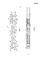
На фиг. 1 показано продольное сечение скважинного устройства для цементирования согласно варианту осуществления настоящего изобретения.In FIG. 1 is a longitudinal sectional view of a downhole cementing device according to an embodiment of the present invention.
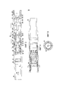
На фиг. 2 показано продольное сечение скважинного устройства для цементирования фиг. 1, установленного в скважинном инструменте.In FIG. 2 shows a longitudinal section of the downhole cementing device of FIG. 1 installed in the downhole tool.
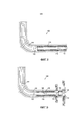
На фиг. 3 показана с увеличением первая, расположенная со стороны устья скважины, концевая область скважинного инструмента с цементирующим устройством на первом аксиальном месте.In FIG. 3 shows with magnification the first, located on the side of the wellhead, the end region of the downhole tool with a cementing device in the first axial location.
На фиг.4 показана с увеличением вторая, расположенная со стороны забоя скважины, концевая область скважинного инструмента.Figure 4 shows with increasing second, located on the bottom of the well, the end region of the downhole tool.
На фиг.5 показано сечение устройства и скважинного инструмента по линии A-A фиг. 4.FIG. 5 shows a cross section of the device and the downhole tool along line A-A of FIG. four.
На фиг.6 схематично показана система ствола скважины, в которой можно применять варианты осуществления настоящего изобретения.6 schematically shows a wellbore system in which embodiments of the present invention can be applied.
На фиг.7 схематично показана система ствола скважины фиг.6, во время цементирования.7 schematically shows the wellbore system of FIG. 6 during cementing.
На фиг.8 схематично показана система ствола скважины фиг.7 и 8 по завершении цементирования.On Fig schematically shows the wellbore system of Fig.7 and 8 after completion of cementing.
На фиг.9 схематично показана система ствола скважины фиг.7, 8 и 9 во время гидроразрыва пласта.Fig. 9 schematically shows the wellbore system of Figs. 7, 8, and 9 during hydraulic fracturing.
ОСУЩЕСТВЛЕНИЕ ИЗОБРЕТЕНИЯDETAILED DESCRIPTION OF THE INVENTION
На фиг. 1 и 2, показано скважинное устройство для цементирования в виде цементировочного дротика 10 согласно варианту осуществления настоящего изобретения. Дротик 10 применяется во время цементирования скважины, дротик 10 спускается в скважину через скважинный инструмент 12 (фиг.2) с некоторым объемом цемента 14 и выполнен с возможностью создания меняющейся точки плотного контакта 16 между дротиком 10 и скважинным инструментом 12, что обеспечивает перемещение цемента 14 через скважинный инструмент 12.In FIG. 1 and 2, a downhole cementing device in the form of a cementing
Как показано на фиг. 1, дротик 10 содержит корпус в виде шпинделя 18 и уплотнительное устройство 20 для создания плотного контакта 16. В показанном варианте осуществления уплотнительное устройство 20 содержит множество аксиально разнесенных уплотнительных элементов 22a, 22b, 22c, 22d, 22e, и применяемый дротик 10 выполнен так, что при спуске дротика 10 через скважинный инструмент 12 точка плотного контакта 16 между дротиком 10 и инструментом 12 меняется аксиально вдоль уплотнительного устройства 20, при этом обеспечивая поддержание плотного контакта между дротиком 10 и инструментом 12 в течение всего времени прохода дротика 10 через инструмент 12.As shown in FIG. 1, the
Шпиндель 18 содержит несколько отдельных модулей 24a, 24b, 24c, 24d, 24e, 24f и 24g. В показанном варианте осуществления модули 24a, 24b, 24c, 24d и 24e представляют собой модули уплотнительных элементов, каждый имеющий уплотнительный элемент 22a, 22b, 22c, 22d, 22e, расположенный или выполненный на нем, а модули 24f и 24g представляют собой дистанцирующие модули. Каждый из модулей 24a to 24g имеет вставное соединительное устройство 26a, 26b, 26c, 26d, 26e, 26f и соответствующее охватывающее соединительное устройство 28a, 28b, 28c, 28d, 28e, 28f и 28g для соединения модулей 24a, 24b, 24c, 24d, 24e, 24f и 24g вместе, которые обеспечивают конструирование дротика 10 с требуемым разносом, обеспечивающим требуемый плотный контакт 16.The
Аксиальный разнос уплотнительных элементов 22a, 22b, 22c, 22d, 22e выполнен так, что точка плотного контакта 16 между дротиком 10 и аксиальным проходом 14 потока инструмента 12 поддерживается по меньшей мере одним из уплотнительных элементов 22a, 22b, 22c, 22d, 22e в течение всего времени прохода дротика 10 через скважинный инструмент 12. Создание и поддержание уплотнения 16 обеспечивает перемещение цемента 14 через скважинный инструмент 12 даже в случае, если один или несколько уплотнительных элементов 22a, 22b, 22c, 22d, 22e расположены на аксиальном месте в скважинном инструменте 12, которое может обеспечивать проход текучей среды вокруг соответствующего уплотнительного элемента 22a, 22b, 22c, 22d, 22e.The axial spacing of the
В показанном варианте осуществления каждый уплотнительный элемент 22a-22e содержит уплотнительный элемент 30a, 30b, 30c, 30d, 30e в форме чашки, отлитый или иначе установленный на своем соответствующем участке 24a-24e шпинделя. Уплотнительные элементы 30a-30e каждый образует угол ϴa, ϴb, ϴc, ϴd, ϴe детали в форме чашки относительно шпинделя 18 и образуют максимальный диаметр Da, Db, Dc, Dd, De на своих дальних концах 32a, 32b, 32c, 32d, 32e. Углы ϴa, ϴb, ϴc, ϴd, ϴe детали в форме чашки и диаметры Da, Db, Dc, Dd, De можно выполнять такими, что точка плотного контакта 16 между дротиком 10 и аксиальным проходом 14 потока инструмента 12 поддерживается по меньшей мере одним из уплотнительных элементов 22a, 22b, 22c, 22d, 22e в течение всего времени прохода дротика 10 через скважинный инструмент 12.In the shown embodiment, each sealing
Показанный на фиг.2-4, скважинный инструмент 12 содержит корпус 34, который образует центральный канал 36 и проходит между расположенным со стороны устья скважины соединительным устройством 38 и расположенным со стороны забоя скважины соединительным устройством 40. Соединительные устройства 38, 40 обеспечивают соединение инструмента 12 с расположенным со стороны устья скважины компонентом S1 колонны и расположенным со стороны забоя скважины компонентом S2 колонны (схематично показано на фиг. 1).2-4, the
Окна 42 прохода текучей среды проходят радиально через стенку корпуса 34 и, когда открываются, окна 42 обеспечивают выход текучей среды из центрального канала 36 корпуса 34. Клапанный элемент в виде втулки 44 может перемещаться аксиально вдоль корпуса 34 из закрытого положения, в котором втулка 44 блокирует или закрывает окна 42, в открытое положение. Перемещение втулки 44 в направлении к своему открытому положению выполняет связанный исполнительный механизм 46.The
Захватывающая втулка 48 расположена со стороны забоя от клапанной втулки 44 и выполнена с возможностью перемещения из конфигурации, не создающей препятствий проходу, в которой объекту, например, шару (не показано) обеспечен свободный проход, в конфигурацию захвата, в которой обеспечен захват объекта, например, шара. Применяемая захватывающая втулка 48 может функционировать, захватывая объект и устанавливая отвод любой текучей среды из центрального канала 36 в направлении наружу через окна 42 прохода текучей среды, когда последние открыты. Дополнительно, захватывающая втулка 48 управляется для перемещения в свою конфигурацию захвата с помощью перемещения клапанной втулки 44 в направлении к ее открытой конфигурации.The
Участок исполнительного механизма инструмента 12 образует профиль 50 пошагового перемещения, созданный на внутренней поверхности корпуса 34.The actuator portion of the
Профиль 50 пошагового перемещения включает в себя множество аксиально разнесенных кольцевых выемок 52a, 52b, 52c, 52d, 52e, 52f, 52g, 52h, выполненных во внутренней поверхности корпуса 34. Индексирующая втулка 54 установлена в корпусе 34 и выполнена с возможностью взаимодействия с профилем 50 пошагового перемещения для перемещения несколькими дискретными шагами линейного перемещения через корпус 34 при проходе соответствующего числа приводящих в действие объектов, например, шаров. Индексирующая втулка 54 приводится в действие дискретными шагами перемещения до достижения места приведения в действие в инструменте 12, где индексирующая втулка 54 сцепляется с клапанной втулкой 44 и перемещает ее в направлении к забою скважины для открытия окна 42.The step-by-
В показанном варианте осуществления индексирующая втулка 50 включает в себя конструкцию 56 трубной стенки, которая образует центральный канал 58, соответствующий центральному каналу 36 корпуса 34. Центральному каналу 58 придан размер, обеспечивающий сквозной проход через него управляющему объекту, например, шару.In the shown embodiment, the
Индексирующая втулка 54 также включает в себя первую и вторую группы элементов 60, 62 сцепления, расположенных по окружности, при этом группа первых элементов 60 сцепления аксиально отнесена от группы вторых элементов 62 сцепления. Элементы сцепления расположены в пазах 64, 66, выполненных проходящими через конструкцию 56 стенки. Применяемые группы элементов 60, 62 сцепления взаимодействуют с профилем 50 пошагового перемещения корпуса 34 для последовательного зацепления проходящим объектом, например, шаром для перемещения втулки 54 пошагового перемещения на один дискретный шаг линейного перемещения. Более конкретно, первая и вторая группы элементов 60, 62 сцепления выполнены с возможностью перемещаться радиально в свои связанные пазы 64, 66 так, что каждая группа элементов 60, 62 сцепления перемещается в режиме альтернативном или со смещением фазы относительно другой группы элементов 60, 62 сцепления при взаимодействии с профилем 50 пошагового перемещения во время перемещения втулки 54 пошагового перемещения через корпус 34. В таком альтернативном радиальном перемещении попеременно перемещаются первая и вторая группы элементов 60, 62 сцепления радиально внутрь и в центральный канал втулки 54 пошагового перемещения, для последовательного зацепления проходящим управляющим объектом. В данном способе проходящий объект может зацеплять элементы 62,64 сцепления одной из первой и второй групп для перемещения втулки 54 пошагового перемещения на длину шага дискретного перемещения, и последующего сцепления элементов 62, 64 сцепления с другой одной из первой и второй групп до завершения шага дискретного перемещения втулки 54 пошагового перемещения.The
Элементы 62, 64 сцепления установлены на дальних концах соответствующих пальцев 68 зажимной конусной втулки, которые крепятся на своих ближних концах к конструкции 56 трубной стенки. Пальцы 68 зажимной конусной втулки выполнены упруго деформирующимися для обеспечения радиального перемещения элементов 62, 64 сцепления при взаимодействии с профилем 50 пошагового перемещения.
В показанном варианте осуществления пальцы 68 зажимной конусной втулки не напряжены, когда элементы 62, 64 сцепления установлены радиально в направлении наружу и при этом выведены из центрального канала. При этом, палец 68 зажимной конусной втулки должен принудительно деформироваться с помощью подходящего взаимодействия между элементами 62, 64 сцепления и профилем 50 пошагового перемещения для перемещения элементов 62, 64 сцепления радиально внутрь в центральный канал для обеспечения зацепление управляющим объектом, например, шаром. В таком устройстве пальцы 66 зажимной конусной втулки могут функционировать, смещая элементы 62, 64 сцепления в направлении радиально наружу из центрального канала. Каждый паз втулки 54 пошагового перемещения вмещает два соответствующих элемента 62, 64 сцепления. Дополнительно, образованы пазы между соответствующими удлиненными ребрами. Каждое ребро включает в себя шлицевой элемент или шпонку, которая размещается в соответствующем продольно проходящих пазах или шпоночных канавках (не показано), выполненных в корпусе 34. Сцепление между шпонками и продольными пазами или шпоночными канавками может функционировать, блокируя вращение втулки 54 пошагового перемещения относительно корпуса 34, при этом, обеспечивая линейное перемещение втулки 54 пошагового перемещения через корпус 34. Такое устройство может обеспечивать выбуривание втулки 54 пошагового перемещения, если потребуется.In the shown embodiment, the
Следует признать, что скважинный инструмент 12 при этом включать в себя профиль, например, профиль 50 пошагового перемещения, или сужение проходного сечения, через которое должен проходить дротик, такое как захватывающая втулка 48 или индексирующая втулка 50, которое может исключать создание непрерывного уплотнения, проходящего по окружности. В варианте сужения проходного сечения, например, утечка текучей среды может обеспечиваться вокруг сужения проходного сечения и таким образом исключать создание непрерывного уплотнения, проходящего по окружности. Альтернативно или дополнительно, форма сужения проходного сечения, которое может, например, содержать зажимную конусную втулку, может исключать создание непрерывного уплотнения, проходящего по окружности.It should be recognized that the
В вариантах осуществления настоящего изобретения, однако, дротик 10 выполнен с возможностью создания меняющейся аксиально вдоль уплотнительного устройства 20 точки плотного контакта 16, что обеспечивает создание плотного контакта 16 в течение всего времени прохода дротика 10 через скважинный инструмент 12.In embodiments of the present invention, however, the
Спуск дротика 10 через скважинный инструмент 12 описан ниже.The descent of the
На фиг. 3, дротик 10 показан установленным в аксиальный проход 14 потока скважинного инструмента 12 в первом аксиальном местоположении. В данном первом местоположении плотный контакт 16 создается первым уплотнительным элементом 22a, который расположен смежно с и в упор к клапанной втулке 44 скважинного инструмента 12.In FIG. 3, the
Вместе с тем, при продвижении дротика 10 в направлении стрелки 90 уплотнительный элемент 22a должен совмещаться с окнами 92, образованными в клапанной втулке (которые применяетcя в итоге для совмещения с окном 42). Соответственно, уплотнительный элемент 22a должен терять свою функцию уплотнения. Вместе с тем, в данный момент уплотнительный элемент 22b должен совмещаться с цилиндрической поверхностью 94 на инструменте 12, и при этом должен устанавливать плотный контакт.However, as the
При продолжении продвижения дротика 10 конкретный уплотнительный элемент, выполняющий функцию уплотнения, может меняться, при этом обеспечивается получение по меньшей мере одного плотного контакта в течение всего времени прохода дротика 10 через скважинный инструмент 12.As the
Понятно, что варианты осуществления, описанные в данном документе, являются только примерами, и что различные модификации можно выполнять без отхода от объема изобретения.It is understood that the embodiments described herein are only examples, and that various modifications can be made without departing from the scope of the invention.
Например, следует признать, что система ствола скважины может содержать множество дротиков 10 и скважинных инструментов 12 аналогичной или отличающейся конфигурации и дротик 10 можно оборудовать за столбом цемента 14 и применять для перемещения цемента 14 через скважинный инструмент 12 или можно устанавливать впереди колонны цемента и применять, например, для размещения ингибитора в скважинном инструменте 12 до цементирования.For example, it should be recognized that the wellbore system may comprise a plurality of
На фиг.6-9, показана система 100 ствола скважины, включающая в себя пробуренный ствол 102 скважины, который проходит от поверхности 104 и пересекает подземный коллектор или пласт 106. В показанном варианте осуществления ствол 102 скважины может содержать наклонно-направленную, проходящую под большим углом или горизонтальную секцию 108.6–9, a
Пласт 106 может содержать углеводороды для извлечения на поверхность 104 с помощью системы 100. Альтернативно, или дополнительно, подземный пласт 106 может являться целью для размещения веществ обработки или текучей среды, нагнетаемой с поверхности 104 с помощью системы 100, например, для увеличения пластового давления и улучшения добычи углеводородов из пласта 106 или соседнего пласта, для целей изоляции, или т.п.The
Трубная колонна 110 проходит через ствол 102 скважины, причем колонна 110 содержит множество инструментов 112 гидроразрыва, распределенных по длине через требуемые интервалы. Один или несколько инструментов 112 могут, например, представлять собой инструменты, такие как инструменты 12, описанные выше.The
На фиг.6 показана система 100 ствола скважины после установки трубной колонны 110 на требуемой глубине.FIG. 6 shows a
Некоторое число работ могут требоваться в течение жизненного цикла системы 100 ствола скважины, которые требуют обеспечения направления текучей среды в пласт 106 и/или из него. Например, можно проводить цементирование для содействия в креплении и опирании по меньшей мере части колонны 110 в стволе 102 скважины, предотвращения неуправляемой миграции текучей среды в кольцевом пространстве 114 между колонной 110 и стволом 102 скважины и/или изоляции конкретной пластовой зоны до выполнения гидроразрыва или обработки пласта для интенсификации притока.A number of activities may be required during the life cycle of the
Как показано на фиг.7, цементирование может включать в себя направление некоторого объема цемента 116 через колонну 110, который затем направляется в кольцевое пространство 114 и нагнетается обратно в направлении к поверхности для заполнения кольцевого пространства 114 или секции кольцевого пространства.As shown in FIG. 7, cementing may include directing a certain volume of
Для управления цементированием первое устройство для цементирования можно устанавливать впереди цемента 116 и соединять с муфтой для посадки и фиксации пробки для цементирования (не показано), а второе устройство для цементирования можно устанавливать за столбом цемента 116. Первое устройство для цементирования может содержать дротик 118, аналогичный или идентичный дротику 10, описанному выше. Второе устройство для цементирования может также или альтернативно содержать дротик 120, аналогичный или идентичный дротику 10, описанному выше. Затем можно подавать увеличенное давление для разрыва или открытия прохода текучей среды, при котором цемент 116 может перемещаться в кольцевое пространство 114. Применяемый второй дротик 120 может также проводить очистку от цемента 116 при перемещении через колонну 110, цемент может иначе создавать препятствия. Прошедший цементирование ствол скважины показан на фиг. 8.To control cementing, a first cementing device can be installed in front of
Альтернативно или дополнительно, пласт 106 может требовать обработки для улучшения темпа добычи или скорости нагнетания, которые требуется получить или восстановить. Методики обработки включают в себя гидравлический разрыв пласта, который включает в себя нагнетание жидкости для гидроразрыва в пласт под высоким давлением и/или с высокой интенсивностью для создания механических трещин в геологической среде. Данные трещины могут увеличивать эффективную проницаемость приствольной зоны скважины и сообщаемость текучей среды между пластом и стволом скважины. Жидкость для гидроразрыва может нести проппант, который функционирует, расклинивая трещины, когда давление гидроразрыва сбрасывается. Кислотная обработка под давлением ниже давления гидроразрыва дает эффект аналогичный гидроразрыву пласта. Такая обработка обычно включает в себя нагнетание химреагента, такого как, кислота, например, соляная кислота, в пласт для химического создания трещин или червоточин в геологической среде. Такая кислотная обработка под давлением ниже давления гидроразрыва может находить применение в геологических средах некоторых типов, например, в карбонатных коллекторах.Alternatively or additionally,
Как показано на фиг. 9, каждый из инструментов 112 включает в себя множество расположенных проходящими по окружности окон 122, которые вначале закрыты. Дополнительно, каждый инструмент 112 включает в себя или связан со скважинным исполнительным механизмом (не показано) который выполнен с функциональной возможностью приведения в действие инструмента 112 для открытия окон 122, обеспечивающих нагнетание текучей среды обработки, например, жидкости для гидроразрыва пласта или кислоты, из колонны 110 в окружающий пласт 106 для создания трещин 124. Каждый инструмент 112 управляется управляющими объектами, например, шарами, которые подаются через колонну 110 с поверхности 104.As shown in FIG. 9, each of the
Инструменты 112 выполнены с функциональной возможностью приведения в действие в требуемой последовательности, таким образом обеспечивая стадийную обработку пласта 106 по длине ствола 102 скважины. Такую возможность последовательного приведения в действие инструментов 112 можно получить с помощью связанного скважинного исполнительного механизма. В показанном варианте осуществления, инструменты 112 выполнены с возможностью последовательного приведения в действие в направлении к устью скважины. Данное показано на фиг. 9, где самый нижний инструмент 112 уже сработал, а смежный инструмент 112, расположенный со стороны устья скважины от него, показан в состоянии приведения в действие с жидкостью для гидроразрыва, направляемой из открытых окон 122 в пласт 106 в направлении стрелок 126. Когда проектный гидроразрыв получен с помощью инструмента 112, следующий расположенный со стороны устья скважины инструмент 112 можно приводить в действие.The
Claims (47)
Applications Claiming Priority (3)
| Application Number | Priority Date | Filing Date | Title |
|---|---|---|---|
| GBGB1304801.2A GB201304801D0 (en) | 2013-03-15 | 2013-03-15 | Downhole apparatus |
| GB1304801.2 | 2013-03-15 | ||
| PCT/GB2014/050790 WO2014140612A2 (en) | 2013-03-15 | 2014-03-14 | Downhole apparatus |
Publications (2)
| Publication Number | Publication Date |
|---|---|
| RU2015144153A RU2015144153A (en) | 2017-04-21 |
| RU2668103C2 true RU2668103C2 (en) | 2018-09-26 |
Family
ID=48226496
Family Applications (1)
| Application Number | Title | Priority Date | Filing Date |
|---|---|---|---|
| RU2015144153A RU2668103C2 (en) | 2013-03-15 | 2014-03-14 | Downhole apparatus and method for well activities (options) |
Country Status (7)
| Country | Link |
|---|---|
| US (1) | US20160047203A1 (en) |
| EP (1) | EP2971469A2 (en) |
| AU (1) | AU2014229783B2 (en) |
| CA (1) | CA2899863C (en) |
| GB (1) | GB201304801D0 (en) |
| RU (1) | RU2668103C2 (en) |
| WO (1) | WO2014140612A2 (en) |
Families Citing this family (4)
| Publication number | Priority date | Publication date | Assignee | Title |
|---|---|---|---|---|
| NO342718B1 (en) * | 2014-08-19 | 2018-07-30 | Frac Tech As | Valve system for a production pipe in a well |
| EP3567210A1 (en) | 2015-05-04 | 2019-11-13 | Weatherford Technology Holdings, LLC | Dual sleeve stimulation tool |
| US11160647B2 (en) | 2016-04-20 | 2021-11-02 | Boston Scientific Scimed, Inc. | Implants and methods for treatments of pelvic conditions |
| US10563478B2 (en) | 2016-12-06 | 2020-02-18 | Saudi Arabian Oil Company | Thru-tubing retrievable subsurface completion system |
Citations (6)
| Publication number | Priority date | Publication date | Assignee | Title |
|---|---|---|---|---|
| US4333530A (en) * | 1976-08-16 | 1982-06-08 | Armstrong Ernest E | Method and apparatus for cementing a casing |
| SU1745896A1 (en) * | 1990-07-16 | 1992-07-07 | Азербайджанский государственный научно-исследовательский и проектный институт нефтяной промышленности | Well cementing device |
| RU2083806C1 (en) * | 1994-12-28 | 1997-07-10 | Татарский Государственный Научно-Исследовательский И Проектный Институт Нефтяной Промышленности | Well completion method |
| WO2004031532A1 (en) * | 2002-10-02 | 2004-04-15 | Baker Hugues Incorporated | Mono-trip well completion |
| RU2316643C2 (en) * | 2004-12-14 | 2008-02-10 | Шлюмбергер Текнолоджи Б.В. | Myltizone well completion method and system (variants) |
| WO2008106639A2 (en) * | 2007-03-01 | 2008-09-04 | Bjservices Company | Improved system and method for stimulating multiple production zones in a wellbore |
Family Cites Families (7)
| Publication number | Priority date | Publication date | Assignee | Title |
|---|---|---|---|---|
| US4880058A (en) * | 1988-05-16 | 1989-11-14 | Lindsey Completion Systems, Inc. | Stage cementing valve |
| GB2414492B (en) * | 2004-05-26 | 2008-03-05 | U W G Ltd | Apparatus and method |
| US7637317B1 (en) * | 2006-10-06 | 2009-12-29 | Alfred Lara Hernandez | Frac gate and well completion methods |
| US8201634B2 (en) * | 2009-05-20 | 2012-06-19 | Baker Hughes Incorporated | Subsea cementing plug system with plug launching tool |
| GB2478995A (en) | 2010-03-26 | 2011-09-28 | Colin Smith | Sequential tool activation |
| GB2478998B (en) | 2010-03-26 | 2015-11-18 | Petrowell Ltd | Mechanical counter |
| WO2012162792A1 (en) * | 2011-05-30 | 2012-12-06 | Packers Plus Energy Services Inc. | Wellbore cementing tool having one way flow |
-
2013
- 2013-03-15 GB GBGB1304801.2A patent/GB201304801D0/en not_active Ceased
-
2014
- 2014-03-14 AU AU2014229783A patent/AU2014229783B2/en not_active Ceased
- 2014-03-14 CA CA2899863A patent/CA2899863C/en not_active Expired - Fee Related
- 2014-03-14 EP EP14713242.7A patent/EP2971469A2/en not_active Withdrawn
- 2014-03-14 WO PCT/GB2014/050790 patent/WO2014140612A2/en not_active Ceased
- 2014-03-14 RU RU2015144153A patent/RU2668103C2/en not_active IP Right Cessation
- 2014-03-14 US US14/776,785 patent/US20160047203A1/en not_active Abandoned
Patent Citations (6)
| Publication number | Priority date | Publication date | Assignee | Title |
|---|---|---|---|---|
| US4333530A (en) * | 1976-08-16 | 1982-06-08 | Armstrong Ernest E | Method and apparatus for cementing a casing |
| SU1745896A1 (en) * | 1990-07-16 | 1992-07-07 | Азербайджанский государственный научно-исследовательский и проектный институт нефтяной промышленности | Well cementing device |
| RU2083806C1 (en) * | 1994-12-28 | 1997-07-10 | Татарский Государственный Научно-Исследовательский И Проектный Институт Нефтяной Промышленности | Well completion method |
| WO2004031532A1 (en) * | 2002-10-02 | 2004-04-15 | Baker Hugues Incorporated | Mono-trip well completion |
| RU2316643C2 (en) * | 2004-12-14 | 2008-02-10 | Шлюмбергер Текнолоджи Б.В. | Myltizone well completion method and system (variants) |
| WO2008106639A2 (en) * | 2007-03-01 | 2008-09-04 | Bjservices Company | Improved system and method for stimulating multiple production zones in a wellbore |
Also Published As
| Publication number | Publication date |
|---|---|
| RU2015144153A (en) | 2017-04-21 |
| WO2014140612A3 (en) | 2014-12-18 |
| WO2014140612A2 (en) | 2014-09-18 |
| AU2014229783A1 (en) | 2015-08-06 |
| AU2014229783B2 (en) | 2017-03-30 |
| EP2971469A2 (en) | 2016-01-20 |
| CA2899863A1 (en) | 2014-09-18 |
| CA2899863C (en) | 2017-07-25 |
| GB201304801D0 (en) | 2013-05-01 |
| US20160047203A1 (en) | 2016-02-18 |
Similar Documents
| Publication | Publication Date | Title |
|---|---|---|
| AU2019201431B2 (en) | Wellbore completion | |
| RU2733998C2 (en) | Multistage stimulation device, systems and methods | |
| US8931557B2 (en) | Wellbore servicing assemblies and methods of using the same | |
| US8863853B1 (en) | Linearly indexing well bore tool | |
| US9458698B2 (en) | Linearly indexing well bore simulation valve | |
| US20120080188A1 (en) | Multi-position Valves for Fracturing and Sand Control and Associated Completion Methods | |
| US9341046B2 (en) | Apparatus configuration downhole | |
| US7762324B2 (en) | Bypass crossover sub selector for multi-zone fracturing processes | |
| US9441467B2 (en) | Indexing well bore tool and method for using indexed well bore tools | |
| CA2769935C (en) | Method and system for cleaning fracture ports | |
| CA2856184A1 (en) | Fracturing valve | |
| US10087712B2 (en) | Pressure actuated downhole tool | |
| RU2668103C2 (en) | Downhole apparatus and method for well activities (options) | |
| US10465461B2 (en) | Apparatus and methods setting a string at particular locations in a wellbore for performing a wellbore operation | |
| US10370916B2 (en) | Apparatus and methods for locating a particular location in a wellbore for performing a wellbore operation | |
| EP4512991A2 (en) | Fracturing using re-openable sliding sleeves | |
| RU2599751C1 (en) | Assembly for gravel packing by "from-toe-to-heel" method and by reverse circulation of excess suspension as per john p.broussard and christopher a.hall method | |
| RU2638200C2 (en) | Downhole device and method | |
| US20260085597A1 (en) | Sleeve for multi-stage wellbore stimulation |
Legal Events
| Date | Code | Title | Description |
|---|---|---|---|
| HZ9A | Changing address for correspondence with an applicant | ||
| MM4A | The patent is invalid due to non-payment of fees |
Effective date: 20200315 |