RU2666113C2 - Oct probe with bowing flexor - Google Patents
Oct probe with bowing flexor Download PDFInfo
- Publication number
- RU2666113C2 RU2666113C2 RU2016111729A RU2016111729A RU2666113C2 RU 2666113 C2 RU2666113 C2 RU 2666113C2 RU 2016111729 A RU2016111729 A RU 2016111729A RU 2016111729 A RU2016111729 A RU 2016111729A RU 2666113 C2 RU2666113 C2 RU 2666113C2
- Authority
- RU
- Russia
- Prior art keywords
- segment
- optical fiber
- cannula
- lumen
- oct probe
- Prior art date
Links
Images


Classifications
-
- A—HUMAN NECESSITIES
- A61—MEDICAL OR VETERINARY SCIENCE; HYGIENE
- A61B—DIAGNOSIS; SURGERY; IDENTIFICATION
- A61B1/00—Instruments for performing medical examinations of the interior of cavities or tubes of the body by visual or photographical inspection, e.g. endoscopes; Illuminating arrangements therefor
- A61B1/06—Instruments for performing medical examinations of the interior of cavities or tubes of the body by visual or photographical inspection, e.g. endoscopes; Illuminating arrangements therefor with illuminating arrangements
- A61B1/07—Instruments for performing medical examinations of the interior of cavities or tubes of the body by visual or photographical inspection, e.g. endoscopes; Illuminating arrangements therefor with illuminating arrangements using light-conductive means, e.g. optical fibres
-
- A—HUMAN NECESSITIES
- A61—MEDICAL OR VETERINARY SCIENCE; HYGIENE
- A61B—DIAGNOSIS; SURGERY; IDENTIFICATION
- A61B3/00—Apparatus for testing the eyes; Instruments for examining the eyes
- A61B3/10—Objective types, i.e. instruments for examining the eyes independent of the patients' perceptions or reactions
- A61B3/102—Objective types, i.e. instruments for examining the eyes independent of the patients' perceptions or reactions for optical coherence tomography [OCT]
-
- A—HUMAN NECESSITIES
- A61—MEDICAL OR VETERINARY SCIENCE; HYGIENE
- A61B—DIAGNOSIS; SURGERY; IDENTIFICATION
- A61B5/00—Measuring for diagnostic purposes; Identification of persons
- A61B5/0059—Measuring for diagnostic purposes; Identification of persons using light, e.g. diagnosis by transillumination, diascopy, fluorescence
- A61B5/0062—Arrangements for scanning
- A61B5/0066—Optical coherence imaging
-
- A—HUMAN NECESSITIES
- A61—MEDICAL OR VETERINARY SCIENCE; HYGIENE
- A61B—DIAGNOSIS; SURGERY; IDENTIFICATION
- A61B5/00—Measuring for diagnostic purposes; Identification of persons
- A61B5/0059—Measuring for diagnostic purposes; Identification of persons using light, e.g. diagnosis by transillumination, diascopy, fluorescence
- A61B5/0082—Measuring for diagnostic purposes; Identification of persons using light, e.g. diagnosis by transillumination, diascopy, fluorescence adapted for particular medical purposes
- A61B5/0084—Measuring for diagnostic purposes; Identification of persons using light, e.g. diagnosis by transillumination, diascopy, fluorescence adapted for particular medical purposes for introduction into the body, e.g. by catheters
Abstract
Description
ПЕРЕКРЕСТНАЯ ССЫЛКА НА РОДСТВЕННЫЕ ЗАЯВКИCROSS REFERENCE TO RELATED APPLICATIONS
[0001] Эта заявка заявляет приоритет предварительной заявки США № 61/877368, поданной 13 сентября 2013 года, описание которой включено в настоящем документе в качестве ссылки в полном объеме.[0001] This application claims priority to provisional application US No. 61/877368, filed September 13, 2013, the description of which is incorporated herein by reference in full.
ОБЛАСТЬ ТЕХНИКИFIELD OF TECHNOLOGY
[0002] Настоящее изобретение относится к устройствам и способам для сканирования тканей с помощью зонда ОКТ ("Оптической Когерентной Томографии"), а более конкретно, к устройству и способам, которые включают возможность перемещения оптического волокна.[0002] The present invention relates to devices and methods for scanning tissues using an OCT probe ("Optical Coherent Tomography"), and more particularly, to a device and methods that include the ability to move an optical fiber.
УРОВЕНЬ ТЕХНИКИBACKGROUND
[0003] Системы оптической когерентной томографии (ОКТ) используются для захвата и генерирования трехмерных изображений слоев тканей пациента. Эти системы содержат зонды ОКТ, которые чаще всего инвазивно вводят в ткани для того, чтобы получить визуализацию тканей в организме пациента. В офтальмологии зонды ОКТ используются для получения детальных изображений тканей в пределах глаза или даже для формирования изображений части глазного яблока, к примеру, сетчатки.[0003] Optical coherent tomography (OCT) systems are used to capture and generate three-dimensional images of patient tissue layers. These systems contain OCT probes, which are most often invasively injected into tissues in order to obtain visualization of tissues in the patient's body. In ophthalmology, OCT probes are used to obtain detailed images of tissues within the eye or even to form images of a part of the eyeball, for example, the retina.
[0004] При использовании оптический луч света направлен через зонд на ткани. Небольшая часть этого света отражается от подповерхностных образований тканей и собирается с помощью того же зонда. Большинство света не отражается, а скорее диффузно рассеивается под большими углами. В обычных изображениях, этот диффузно рассеянный свет является одной из причин образования фона, который затеняет изображение. Тем не менее, при проведении ОКТ, техника, называемая интерферометрией, записывает длины оптического пути улавливаемых фотонов, и предоставляет данные об отклонении большинства фотонов, которые рассеиваются многократно до обнаружения. В результате это приводит к получению изображений, которые являются более четкими и которые распространяются в глубину тканей.[0004] In use, an optical beam of light is directed through the probe at the tissue. A small part of this light is reflected from subsurface tissue formations and is collected using the same probe. Most light is not reflected, but rather diffusely scattered at large angles. In ordinary images, this diffusely scattered light is one of the reasons for the formation of a background that obscures the image. However, during OCT, a technique called interferometry records the optical path lengths of captured photons and provides data on the deviation of most photons, which are scattered many times before detection. As a result, this results in images that are clearer and that extend deep into the tissues.
СУЩНОСТЬ ИЗОБРЕТЕНИЯSUMMARY OF THE INVENTION
[0005] В приводимом в качестве примера аспекте настоящее изобретение относится к зонду OКT для получения изображения тканей пациента. Зонд ОКТ содержит канюлю, содержащую просвет и имеющую ось канюли. Зонд ОКТ также содержит светопроводящее оптическое волокно с возможностью селективного перемещения, расположенное внутри просвета и имеющее дистальный конец. Оптическое волокно может быть приспособлено для излучения света из дистального участка. Упругий элемент проходит через просвет и содержит первый сегмент и второй сегмент. Первый сегмент может быть соединен с оптическим волокном. Привод может быть сконфигурирован для осевого смещения второго сегмента, в результате чего оптическое волокно латерально смещается.[0005] In an exemplary aspect, the present invention relates to an OCT probe for imaging patient tissue. The OCT probe contains a cannula containing a lumen and having a cannula axis. The OCT probe also contains a selective conductive optical fiber located inside the lumen and having a distal end. The optical fiber may be adapted to emit light from a distal portion. The elastic element passes through the lumen and contains a first segment and a second segment. The first segment can be connected to an optical fiber. The drive can be configured to axially offset the second segment, as a result of which the optical fiber is laterally displaced.
[0006] В одном аспекте изобретения упругий элемент содержит изгиб, а второй сегмент проходит от изгиба в наклонном направлении. В одном аспекте изобретения второй сегмент сконфигурирован с возможностью изгибаться в тех случаях, когда привод перемещает второй сегмент в первом осевом направлении. В одном аспекте изобретения упругий элемент содержит смещающий элемент, который смещается вместе с оптическим волокном в надлежащее положение внутри канюли.[0006] In one aspect of the invention, the resilient member comprises a bend, and the second segment extends from the bend in an oblique direction. In one aspect of the invention, the second segment is configured to bend when the drive moves the second segment in the first axial direction. In one aspect of the invention, the resilient member comprises a biasing member that is biased with the optical fiber to a proper position within the cannula.
[0007] В одном аспекте изобретения может содержаться второй упругий элемент. Второй упругий элемент может проходить через просвет и содержать третий сегмент и четвертый сегмент. Третий сегмент может быть присоединен к оптическому волокну на стороне оптического волокна, которая является противоположной первому сегменту. В одном аспекте изобретения привод может быть функционально соединен со вторым сегментом и четвертым сегментом, и выполнен с возможностью попеременно смещать один из второго сегмента или четвертого сегмента в первом осевом направлении, а другой из этих второго сегмента или четвертого сегмента во втором осевом направлении, противоположном первому осевому направлению. В одном аспекте изобретения второй упругий элемент может содержать изгиб, а четвертый сегмент может проходить от изгиба в наклонном направлении. Четвертый сегмент может быть сконфигурирован для сгибания в тех случаях, когда четвертый сегмент смещается либо в первом осевом направлении, или же в указанном осевом направлении.[0007] In one aspect of the invention, a second resilient member may be included. The second elastic element may extend through the lumen and comprise a third segment and a fourth segment. The third segment can be attached to the optical fiber on the side of the optical fiber, which is opposite to the first segment. In one aspect of the invention, the drive may be operatively coupled to a second segment and a fourth segment, and configured to alternately shift one of the second segment or fourth segment in a first axial direction and the other of these second segment or fourth segment in a second axial direction opposite to the first axial direction. In one aspect of the invention, the second elastic element may comprise a bend, and the fourth segment may extend from the bend in an oblique direction. The fourth segment can be configured to fold in cases where the fourth segment is displaced either in the first axial direction or in the specified axial direction.
[0008] В одном аспекте изобретения привод сконфигурирован таким образом, чтобы сместить первый сегмент в первом осевом направлении при перемещении второго сегмента во втором осевом направлении, противоположном первому осевому направлению, для того чтобы вызвать смещение оптического волокна в латеральном направлении. В одном аспекте изобретения первый сегмент может быть более коротким, чем второй сегмент. В одном аспекте изобретения линза может быть расположена в просвете канюли дистальнее оптического волокна с возможностью перемещения вместе с волокном. В одном аспекте изобретения канюля может быть подобрана по размерам для введения в глаз пациента с целью сканирования сетчатки глаза.[0008] In one aspect of the invention, the drive is configured to displace the first segment in the first axial direction while moving the second segment in the second axial direction opposite to the first axial direction in order to cause the optical fiber to shift in the lateral direction. In one aspect of the invention, the first segment may be shorter than the second segment. In one aspect of the invention, the lens may be located in the lumen of the cannula distal to the optical fiber with the ability to move with the fiber. In one aspect of the invention, the cannula can be sized to be inserted into the patient’s eye to scan the retina.
[0009] В одном аспекте изобретения упругий элемент может содержать, по существу, трубчатую часть, а второй сегмент может проходить через эту трубчатую часть. В одном аспекте изобретения трубчатая часть может быть зафиксирована в надлежащем месте по отношению к канюле. В одном аспекте изобретения первый сегмент может быть присоединен к оптическому волокну через отверстие, при этом оптическое волокно проходит через отверстие.[0009] In one aspect of the invention, the resilient member may comprise a substantially tubular portion, and a second segment may extend through this tubular portion. In one aspect of the invention, the tubular portion may be locked in place in relation to the cannula. In one aspect of the invention, the first segment can be attached to the optical fiber through the hole, with the optical fiber passing through the hole.
[0010] В другом приводимом в качестве примера аспекте настоящего изобретения зонд ОКТ может содержать канюлю с просветом. Канюля может также содержать ось канюли. Зонд ОКТ может также содержать светопроводящее оптическое волокно с возможностью селективного перемещения, расположенное внутри просвета канюли, и имеющее дистальный конец. Оптическое волокно может быть приспособлено для излучения света из дистального конца. Упругий элемент может содержать первый сегмент и второй сегмент, проходящие через просвет, и может иметь отверстие, образованное в нем, через которое проходит оптическое волокно. Привод может быть сконфигурирован для осевого перемещения по меньшей мере одного из следующего: первого сегмента или второго сегмента, чтобы вызвать упругий изгиб одного из указанных: первого сегмента или второго сегмента, а также латеральное смещение оптического волокна.[0010] In another exemplary aspect of the present invention, the OCT probe may include a lumen cannula. The cannula may also comprise the axis of the cannula. The OCT probe may also contain a selective conductive optical fiber located inside the lumen of the cannula and having a distal end. The optical fiber can be adapted to emit light from the distal end. The elastic element may comprise a first segment and a second segment passing through the lumen, and may have an opening formed therein through which the optical fiber passes. The drive can be configured to axially move at least one of the following: the first segment or second segment to cause elastic bending of one of the following: the first segment or second segment, as well as lateral displacement of the optical fiber.
[0011] В одном аспекте изобретения упругий элемент может содержать трубчатую часть. Второй сегмент может проходить через эту трубчатую часть. В одном аспекте изобретения трубчатая часть первого сегмента может быть зафиксирована в надлежащем месте по отношению к канюле. В одном аспекте изобретения привод может быть выполнен с возможностью смещения в осевом направлении первого сегмента для того, чтобы вызвать латеральное смещение оптического волокна.[0011] In one aspect of the invention, the resilient member may comprise a tubular portion. A second segment may extend through this tubular portion. In one aspect of the invention, the tubular portion of the first segment can be locked in place in relation to the cannula. In one aspect of the invention, the drive may be configured to axially displace the first segment in order to cause lateral displacement of the optical fiber.
[0012] В одном аспекте изобретения настоящее изобретение относится к способу сканирования зондом OКT. Способ может включать излучение света на ткани пациента оптическим волокном из просвета канюли зонда OКT. Способ может также включать латеральное перемещение оптического волокна в просвете канюли в ответ на осевое смещение части упругого элемента, соединенного с оптическим волокном.[0012] In one aspect of the invention, the present invention relates to a method for scanning with an OKT probe. The method may include emitting light onto the patient’s tissue with an optical fiber from the cannula of the OCT probe. The method may also include lateral movement of the optical fiber in the lumen of the cannula in response to the axial displacement of a portion of the elastic member connected to the optical fiber.
[0013] В одном аспекте изобретения оптическое волокно проходит через отверстие в упругом элементе. В одном аспекте изобретения упругий элемент может содержать первый сегмент, второй сегмент и трубчатую часть. Первый сегмент может проходить через эту трубчатую часть.[0013] In one aspect of the invention, an optical fiber passes through an opening in an elastic member. In one aspect of the invention, the resilient member may comprise a first segment, a second segment, and a tubular portion. The first segment may extend through this tubular portion.
[0014] Следует понимать, что как предшествующее общее описание, так и последующее подробное описание являются только пояснительными и приводятся в качестве примера по своему характеру, и предназначены для обеспечения понимания настоящего изобретения без ограничения объема настоящего изобретения. В этой связи дополнительные аспекты, признаки и преимущества настоящего изобретения будут очевидны специалистам в данной области техники из следующего подробного описания.[0014] It should be understood that both the foregoing general description and the following detailed description are illustrative only and are exemplary in nature, and are intended to provide an understanding of the present invention without limiting the scope of the present invention. In this regard, additional aspects, features and advantages of the present invention will be apparent to those skilled in the art from the following detailed description.
КРАТКОЕ ОПИСАНИЕ ГРАФИЧЕСКИХ МАТЕРИАЛОВBRIEF DESCRIPTION OF GRAPHIC MATERIALS
[0015] Сопроводительные графические материалы иллюстрируют варианты реализации устройств и способов настоящего изобретения, описанных в настоящем документе, и вместе с описанием служат для объяснения принципов настоящего изобретения.[0015] The accompanying drawings illustrate embodiments of the devices and methods of the present invention described herein, and together with the description, serve to explain the principles of the present invention.
[0016] На Фиг. 1 представлена блок-схема приводимой в качестве примера системы обработки изображений ОКТ.[0016] In FIG. 1 is a block diagram of an exemplary OCT image processing system.
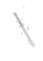
[0017] На Фиг. 2 представлен вид в поперечном разрезе приводимого в качестве примера зонда ОКТ.[0017] FIG. 2 is a cross-sectional view of an exemplary OCT probe.
[0018] На Фиг. 3 представлен подробный вид в поперечном разрезе приводимого в качестве примера зонда ОКТ, показанного на Фиг. 2.[0018] FIG. 3 is a detailed cross-sectional view of an exemplary OCT probe shown in FIG. 2.
[0019] На Фиг. 4 представлен подробный вид в поперечном разрезе приводимого в качестве примера зонда ОКТ, показанного на Фиг. 2.[0019] In FIG. 4 is a detailed cross-sectional view of an exemplary OCT probe shown in FIG. 2.
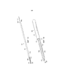
[0020] На Фиг. 5 представлен подробный вид в поперечном разрезе еще одного приводимого в качестве примера зонда ОКТ.[0020] In FIG. 5 is a detailed cross-sectional view of yet another exemplary OCT probe.
[0021] На Фиг. 6 представлен подробный вид в поперечном разрезе еще одного приводимого в качестве примера зонда ОКТ.[0021] In FIG. 6 is a detailed cross-sectional view of yet another exemplary OCT probe.
[0022] На Фиг. 7 представлен подробный вид в поперечном разрезе еще одного приводимого в качестве примера зонда ОКТ.[0022] In FIG. 7 is a detailed cross-sectional view of yet another exemplary OCT probe.
[0023] На Фиг. 8 и 9 представлен подробный вид в поперечном разрезе другого приводимого в качестве примера зонда ОКТ.[0023] In FIG. 8 and 9 are a detailed cross-sectional view of another exemplary OCT probe.
[0024] На Фиг. 10 представлен подробный вид в поперечном разрезе еще одного приводимого в качестве примера зонда ОКТ.[0024] In FIG. 10 is a detailed cross-sectional view of yet another exemplary OCT probe.
[0025] На Фиг. 11 представлен перспективный вид в поперечном разрезе еще одного приводимого в качестве примера зонда ОКТ.[0025] In FIG. 11 is a cross-sectional perspective view of yet another exemplary OCT probe.
[0026] На Фиг. 12 представлен подробный вид части приводимого в качестве примера зонда ОКТ, показанного на Фиг. 11.[0026] In FIG. 12 is a detailed view of a portion of an exemplary OCT probe shown in FIG. eleven.
[0027] На Фиг. 13 представлен перспективный вид приводимого в качестве примера упругого элемента.[0027] In FIG. 13 is a perspective view of an exemplary resilient member.
[0028] На Фиг. 14 представлен подробный вид приводимого в качестве примера упругого элемента, показанного на Фиг. 13.[0028] In FIG. 14 is a detailed view of an exemplary resilient member shown in FIG. 13.
ПОДРОБНОЕ ОПИСАНИЕ ИЗОБРЕТЕНИЯDETAILED DESCRIPTION OF THE INVENTION
[0029] Для целей содействия пониманию принципов настоящего изобретения ссылки в данной работе будут сделаны к приводимым в качестве примера вариантам реализации изобретения, которые проиллюстрированы на графических материалах, а для описания вышеуказанного будут использоваться конкретные формулировки. Тем не менее, следует понимать, что никакого ограничения в объеме изобретения не предусматривается. Любые изменения и дополнительные модификации описанных устройств, инструментов, способов и дальнейшее применение принципов настоящего изобретения полностью предполагаются как обычно происходящие для специалистов в этой области техники, к которой относится изобретение. В частности, полностью предполагается, что конструктивные особенности, составляющие элементы и/или этапы, описанные со ссылкой на один из вариантов реализации изобретения, могут быть объединены с конструктивными особенностями, составляющими элементами и/или этапами, описанными по отношению к другим вариантам реализации настоящего изобретения. Тем не менее, для краткости изложения, многочисленные итерации этих комбинаций не будут описано отдельно. Для упрощения в некоторых примерах одинаковые ссылочные позиции использованы на всех графических материалах для обозначения одинаковых или подобных частей.[0029] In order to facilitate understanding of the principles of the present invention, references in this work will be made to exemplary embodiments of the invention, which are illustrated in graphic materials, and specific language will be used to describe the above. However, it should be understood that no limitation in the scope of the invention is not provided. Any changes and additional modifications of the described devices, tools, methods and further application of the principles of the present invention are fully expected as usually occurring to specialists in this field of technology to which the invention relates. In particular, it is fully assumed that the design features constituting the elements and / or steps described with reference to one embodiment of the invention can be combined with the design features, constituent elements and / or steps described in relation to other embodiments of the present invention. . However, for brevity, the numerous iterations of these combinations will not be described separately. For simplicity, in some examples, the same reference numerals are used on all graphic materials to denote the same or similar parts.
[0030] Настоящее изобретение относится в целом к зондам ОКТ, системам ОКТ и способам, с помощью которых сканируют ткани для того, чтобы получить ОКТ изображение. Зонд содержит канюлю, сконфигурированную с возможностью инвазивного введения в ткани пациента, например, в глаз. В канюле находится линза и оптическое волокно. Оптическое волокно направляет свет через линзу и захватывает отраженный свет, который проходит обратно через линзу. Для того чтобы получить сканирование области или линии ткани, а не всего лишь точки по меньшей мере часть волокна перемещается вперед и назад в пределах канюли по отношению к линзе, и выходящий из линзы свет отклоняется под углом. В силу того, что канюля, которую вводят в ткани пациента, имеет требуемое малое поперечное сечение, перемещение волокна внутри канюли создает проблемы.[0030] The present invention relates generally to OCT probes, OCT systems, and methods by which tissues are scanned in order to obtain an OCT image. The probe contains a cannula configured to be invasively inserted into the patient’s tissue, for example, into the eye. There is a lens and optical fiber in the cannula. An optical fiber directs light through the lens and captures the reflected light that passes back through the lens. In order to scan a region or line of tissue, and not just a point, at least a portion of the fiber moves back and forth within the cannula with respect to the lens, and the light exiting the lens is deflected at an angle. Due to the fact that the cannula, which is inserted into the patient’s tissue, has the required small cross section, the movement of the fiber inside the cannula creates problems.
[0031] Приводимые в качестве примера аспекты изобретения, описанные в настоящем документе, используют технику латерального перемещения по меньшей мере конца волокна внутри канюли с использованием упругого элемента. Упругий элемент проходит от местоположения вдоль дистального участка волокна к проксимальному местоположению, которое может быть расположено вне канюли, например, в корпусе зонда. Волокно может быть затем смещено латерально с помощью вытягивания или вталкивания упругого элемента, который оказывает боковое воздействие для латерального смещения волокна. Упругий элемент упруго изгибают или сгибают для того, чтобы вызвать усилие в латеральном направлении, которое смещает волокно.[0031] The exemplary aspects of the invention described herein use the technique of laterally moving at least the end of a fiber within a cannula using an elastic member. The elastic element extends from a location along the distal portion of the fiber to a proximal location that can be located outside the cannula, for example, in the probe body. The fiber can then be laterally displaced by pulling or pushing in the elastic element, which has a lateral effect for lateral displacement of the fiber. The elastic element is elastically bent or bent in order to cause a force in the lateral direction that biases the fiber.
[0032] Фиг. 1 иллюстрирует приводимую в качестве примера ОКТ систему обработки изображений 100. Система 100 содержит консоль 102, интерфейс пользователя 104 и зонд ОКТ 106. Консоль 102 содержит ОКТ привод, в том числе, наряду с некоторыми другими элементами, источник света 108 и контроллер 110. Источник света 108 сконфигурирован для обеспечения светом ближней длинноволновой инфракрасной области спектра (NIR), который отражается от биологической ткани-мишени и захватывается с помощью зонда ОКТ 106. В других реализациях изобретения может быть использовано излучение, которое имеет другие частоты. В ОКТ может быть использована любая определенная ширина полосы частот света. Для многих офтальмологических применений может быть использован свет ближней инфракрасной области спектра. Например, в некоторых офтальмологических применениях может быть использована ширина полосы частот излучения от 700 до 900 нм со средней длиной волны 800 нм. В других примерах может быть использован диапазон длин волн излучения от 1250 до 1450 нм со средней длиной волны 1350 нм. Более того, может быть использован диапазон длин волн излучения от 1400 до 1600 нм со средней длиной волны 1500 нм. В дополнение к этому, несмотря на то, что примеры, приведенные в данном документе, могут быть описаны в контексте офтальмологических процедур, объем применения не ограничивается. В значительной степени, идеи, представленные в настоящем документе, также могут быть использованы для других применений. Например, идеи могут быть использованы в других медицинских процедурах. Более того, идеи, описанные в настоящем документе, могут быть использованы в любой другой подходящей области. В частности, описанные идеи могут быть использованы в областях за пределами области медицины.[0032] FIG. 1 illustrates an exemplary OCT
[0033] В некоторых вариантах реализации изобретения источник света 108 может содержать суперлюминесцентные светодиоды, лазеры ультракоротких импульсов, или суперконтинуумные лазеры, которые обеспечивают относительно длинноволновую область света. Контроллер 110 может содержать процессор и запоминающее устройство, которое может содержать исполняемую программу для управления источником света 108, интерфейсом пользователя 104 и зондом ОКТ 106, а также для выполнения и представления функций и процессов для реализации процедуры получения ОКТ изображения. В некоторых реализациях изобретения источник света 108 может излучать свет ближней инфракрасной области спектра (NIR), который может быть в диапазоне от 700 нм до 900 нм, от 1250 нм до 1450 нм, и от 1400 нм до 1600 нм. В частности, в некоторых реализациях изобретения источник света 108 может излучать свет ближней инфракрасной области спектра (NIR), в диапазоне длин волн с центральными частотами 850 нм, 1060 нм или 1350 нм. Эти частотные диапазоны приведены всего лишь в качестве примеров, и изобретение не предназначено быть ограниченным этим. Наоборот, способы, используемые в настоящем документе, могут включать длину волн излучения любой требуемой частоты или диапазона частот.[0033] In some embodiments, the
[0034] В некоторых вариантах реализации изобретения интерфейс пользователя 104 выполнен или сформирован в виде части консоли 102. Интерфейс пользователя 104 может представлять собой дисплей, сконфигурированный для представления изображения для пользователя или пациента, а также отображения сканируемой с помощью зонда 106 ткани во время процедуры получения ОКТ изображения. Интерфейс пользователя 104 может также содержать устройства или системы ввода, имеющие в своем составе, в качестве примера, не имеющего ограничительного характера, клавиатуру, мышь, джойстик, наборной диск и/или кнопки, наряду с некоторыми другими устройствами ввода.[0034] In some embodiments of the invention, the
[0035] Зонд ОКТ 106 имеет такой размер и форму, чтобы мог размещаться в руке пользователя, например, хирурга или другого медицинского работника, и мог быть введен в организм пациента. В проиллюстрированном варианте реализации изобретения зонд ОКТ 106 находится в электрической и оптической связи с консолью 102 и сконфигурирован с возможностью подавать свет от источника света 108 на ткани пациента в целях получения изображения тканей.[0035] The
[0036] Фиг. 2 иллюстрирует приводимый в качестве примера зонд ОКТ 106. Как будет описано более подробно ниже, зонд ОКТ 106 содержит механизм для смещения оптического волокна, несущего свет от источника света 108 таким образом, что происходит перемещение волокна по отношению к линзе. Свет из оптического волокна преломляется через линзу, вследствие чего луч света отклоняется в угловом направлении. Угловое сканирование производится путем перемещения положения волокна в латеральном направлении по отношению к линзе, такой как линза 210, описанная ниже.[0036] FIG. 2 illustrates an
[0037] Продолжая ссылаться на Фиг. 2, зонд ОКТ 106 содержит корпус зонда 200, канюлю 202, осветительную систему 204, и систему привода 206. Корпус зонда 200 сконфигурирован с возможностью захвата и манипулирования пользователем, например, во время ОКТ процедуры. Часть корпуса 200 может образовывать рукоятку или ручку и может вмещать составляющие элементы зонда ОКТ 106. Корпус зонда 200 содержит дистальный конец 207, из которого выступает канюля 202. Канюля 202 содержит центральную ось 203 и сконфигурирована и устроена с возможностью проникновения в ткани пациента для того, чтобы получить ОКТ изображение.[0037] Continuing to refer to FIG. 2, the
[0038] Канюля 202 содержит дистальный конец 208 и проксимальный конец 209. Проксимальный конец 209 канюли 202 расположен внутри корпуса зонда 200 и прикреплен к нему. В некоторых вариантах реализации изобретения просвет 216 канюли 202 принимает часть системы привода 206 и осветительной системы 204 способом, описанным ниже. В некоторых примерах канюля 202 может быть изготовлена по определенному размеру для введения и использования в глазу и может быть использована для сканирования тканей пациента. Например, в некоторых примерах, канюля 202 может быть использована для сканирования тканей глаза пациента, таких как ткани сетчатки.[0038] The
[0039] Осветительная система 204 содержит линзу 210 и оптическое волокно 214. Осветительная система 204 принимает и передает свет от источника света 108. В некоторых реализациях изобретениях линза 210 может представлять собой градиентную линзу с переменным показателем преломления ("GRIN"), с плоскими поверхностями, через которые может пройти свет из оптического волокна 214. В некоторых реализациях изобретения градиентный показатель преломления может быть сферическим, осевым или радиальным. Таким образом, в других примерах линза 210 может представлять собой сферическую линзу. В то же время в других примерах может быть использована линза, которая имеет другие формы.[0039] The
[0040] Оптическое волокно 214 сконфигурировано с возможностью передачи света от источника света 108 к линзе 210, и, в конечном счете, к находящимся под наблюдением тканям. В некоторых реализациях изобретения оптическое волокно 214 может представлять собой единичное волокно. В других примерах оптическое волокно 214 может представлять собой пучок оптических волокон. В некоторых примерах оптическое волокно 214 может быть непрерывным оптическим волокном, проходящим от источника света 108 к дистальному концу 218 оптического волокна 214. В других примерах оптическое волокно 214 может быть сформировано из двух или более оптических волокон, проходящих от источника света 108. Кроме того, в еще других вариантах реализации изобретения оптическое волокно 214 может принимать свет от источника света 108 за счет оптического волокна, проходящего от консоли 102 до зонда ОКТ 106.[0040] The
[0041] В некоторых примерах проксимальный конец (не показан) оптического волокна 214 может быть расположен вблизи источника света 108 (Фиг. 1), в то время как дистальный конец 218 может быть расположен вблизи линзы 210 способом, направляющим свет через линзу 210. Как проиллюстрировано на Фиг. 2, оптическое волокно 214 не присоединено непосредственно к линзе 210, а линза 210 является зафиксированной на месте по отношению к канюле 202. Соответственно, оптическое волокно 214 может перемещаться относительно канюли 202 и линзы 210. Дистальный конец 218 оптического волокна 214 может быть расположен на заранее определенном расстоянии от поверхности 211 линзы 210 для того, чтобы достичь, например, требуемого оптического фокусного расстояния сквозь линзу 210.[0041] In some examples, the proximal end (not shown) of the
[0042] Система привода 206 может содержать привод 220 и перемещающий элемент, показанный в качестве упругого элемента 222. Система привода 206 выполнена с возможностью перемещения оптического волокна 214 в латеральном направлении относительно канюли 202 для того, чтобы обеспечить как одномерные, так и двумерные направленные сканирования для создания 2D или 3D изображений с помощью ОКТ системы обработки изображений 100. Система привода 206 выполнена с возможностью смещения упругого элемента 222 в направлении стрелок 234 и/или 235. Упругий элемент 222, в свою очередь, выполнен с возможностью смещения по меньшей мере части оптического волокна 214 в латеральном направлении по отношению к канюле 202 и линзе 210. Кроме того, упругий элемент 222 выполнен с возможностью смещения оптического волокна 214 таким образом, чтобы свести к минимуму любое изменение в расстоянии между дистальным концом 218 оптического волокна 214 и проксимальным концом 211 линзы 210. В некоторых реализациях изобретения это минимальное изменение расстояния между дистальным концом 218 оптического волокна 214 и проксимальным концом 211 линзы 210 связано с малой величиной углового смыкания оптического волокна 214 по отношению к линзе 210.[0042] The
[0043] Привод 220 может представлять собой микромотор микроэлектромеханических систем (MEMS), линейный двигатель, пьезоэлектрический двигатель, электромагнитный двигатель, пневматический поршень, диафрагмы, электромагнит или другой элемент или механизм. Например, привод 220 может быть любым устройством или механизмом, который выполнен с возможностью смещать упругий элемент 222 в направлении стрелок 234, 235. Привод 220 сконфигурирован для передачи усилия на упругий элемент 222 для физического перемещения упругого элемента 222 вдоль осевого направления волокна, как проиллюстрировано стрелками 234, 235, связанных с упругим элементом 222 согласно Фиг. 2. В некоторых вариантах реализации изобретения привод 220 является электрическим приводом и электрически соединен с консолью 102 посредством силового кабеля (не показан), проходящего от зонда ОКТ 106. В других вариантах реализации изобретения привод 220 расположен в корпусе датчика 200 и сконфигурирован, чтобы быть автономным. Соответственно, в некоторых реализациях изобретения привод 220 может содержать источник питания, который обеспечивает подачу питания к приводу 220 для того, чтобы физически смещать упругий элемент 222 с целью перемещения оптического волокна 214 внутри канюли 202. В некоторых реализациях изобретения источник питания может быть расположен на корпусе 200 или же внутри него. В некоторых реализациях изобретения источник питания может представлять собой батарею или же содержать ее. В некоторых реализациях изобретения привод 220 может быть сконфигурирован для перемещения упругого элемента 222 в возвратно-поступательном движении, прикладывая усилие или нагрузку к упругому элементу 222 для того, чтобы создать отклоняющее усилие на оптическом волокне 214. Например, привод 220 может быть сконструирован с возможностью возвратно-поступательного движения упругого элемента 222 в направлении стрелок 234, 235, как описано ниже.[0043] The
[0044] Упругий элемент 222 может быть сформирован из эластично изгибаемого материала. Например, в некоторых реализациях изобретения упругий элемент 222 может быть изготовлен из металла или сплава, такого как нержавеющая сталь. Некоторые реализации сплава имеют в своем составе сплавы с памятью формы, такие как нитинол. Также предполагаются другие материалы. В варианте реализации изобретения, проиллюстрированном на Фиг. 2, упругий элемент 222 является сложенным и содержит сгиб или изгиб 230, формирующий наиболее дистальную часть упругого элемента 222. В сложенном состоянии упругий элемент 222 содержит два сегмента 232а, 232b, которые проходят от изгиба 230 в проксимальном направлении внутри канюли 202. Концы 224, 226 упругого элемента 222 примыкают к приводу 220 и приспособлены быть приведенными в действие приводом 220 в направлении, по существу, параллельном направлению оптического волокна 214 и оси канюли 203, как это проиллюстрировано стрелками 234, 235. В проиллюстрированном примере упругий элемент 222 является достаточно жестким для того, чтобы служить опорой для оптического волокна 214 внутри канюли 202 без дополнительных фиксаторов или креплений. Соответственно, упругий элемент 222 выполнен с возможностью служить опорой для волокна 214 внутри канюли 202.[0044] The
[0045] Как проиллюстрировано на Фиг. 2, сегмент 232a расположен рядом с оптическим волокном 214 и соединен с ним. Сегмент 232a может быть соединен с оптическим волокном 214 в одном или более местах вблизи изгиба 230. В некоторых реализациях изобретения сегмент 232a может быть соединен с волокном 214, по существу, вдоль всей длины сегмента 232a. В других реализациях изобретения только дистальная часть сегмента 232a может быть соединена с оптическим волокном 214. Сегмент 232b выступает под косым углом от оптического волокна 214 в месте изгиба 230, а затем изгибается в проксимальном направлении в сторону привода 220.[0045] As illustrated in FIG. 2,
[0046] На Фиг. 3 и 4 проиллюстрировано смещение, приданное оптическому волокну 214 за счет перемещения сегментов 232а, 232b упругого элемента 222 в указанных стрелками направлениях 234, 235. Перемещение оптического волокна 214, которое проиллюстрировано на Фиг. 3 и 4, отображает сканирующее движение, которое может быть использовано в ходе проведения ОКТ сканирования. Изгибание упругого элемента 222 приводит к соответствующему отклонению или изгибу оптического волокна 214. В результате этого изгиба оптического волокна 214 дистальный конец 218 оптического волокна 214 выходит за пределы местоположения оптического волокна 214, соприкасающегося со смещенным упругим элементом 222. Таким образом, дистальный конец оптического волокна 214 может быть смещен в латеральных направлениях, обозначенных стрелками 237, 239 внутри канюли 222 для выполнения цикла сканирования. В некоторых реализациях изобретения дистальная часть оптического волокна 214 может быть смещена внутри канюли 222 в направлениях, обозначенных стрелками 237, 239 для того, чтобы выполнить цикл сканирования. Ссылаясь в первую очередь на Фиг. 3, привод 220 нажимает на сегмент 232b в направлении, указанном стрелкой 235, и толкает сегмент 232а в направлении, указанном стрелкой 234. Это приводит к упругому изгибанию сегмента 232b наружу и, в приводимом проиллюстрированном примере, приводит к соприкосновению с внутренней стенкой канюли 238. В некоторых вариантах реализации изобретения внутренняя стенка канюли 238 может действовать в качестве жесткой опоры или подпорки, с которой сегмент 232b входит в плотное соприкосновение. Дополнительное нажатие вызывает изгибание сегмента 232b для смещения дистального конца оптического волокна 214 в направлении, указанном стрелкой 237, и по способу, приведенному на Фиг. 3. Соответственно, отклонение или изгиб упругого элемента 222 создает латеральное перемещение, которое смещает оптическое волокно 214. Тем не менее, в других реализациях изобретения упругий элемент 222 может быть выполнен с возможностью смещения оптического волокна 214 в латеральном направлении без соприкосновения упругого элемента 222 с внутренней стенкой канюли 238.[0046] FIG. 3 and 4 illustrate the offset given to the
[0047] На Фиг. 4 проиллюстрирована аналогичная часть зонда ОКТ 106 с оптическим волокном 214, смещенным в противоположном направлении от показанного на Фиг. 3. В данном примере привод 220 вытягивает сегмент 232b в направлении, указанном стрелкой 234, и толкает сегмент 232а в направлении, указанном стрелкой 235, вместо того, чтобы толкать дистальный конец 218 оптического волокна 214. Это приводит к перемещению оптического волокна 214 латерально в направлении, указанном стрелкой 239 через просвет 216 канюли 202, чтобы обеспечить ОКТ сканирование. Как можно видеть, оптическое волокно 214 приводится в движение в направлении, указанном стрелкой 239, которое является противоположным направлению, указанному стрелкой 237, что приведено на Фиг. 3. Латеральное расстояние сканирования, то есть величина латерального смещения части оптического волокна 214 (например, дистального конца 218), связана с расположением изгиба 230 по отношению к дистальному концу 218 оптического волокна 214 и угловому изгибанию упругого элемента 222. Перемещение упругого элемента 222 приводит к отклонению или изгибанию оптического волокна 214 вдоль всей длины оптического волокна 214 вблизи места изгиба 230. Это изгибание оптического волокна 214 смещает дистальный конец 218 в направлении, указанном стрелками 237 и 239.[0047] FIG. 4 illustrates a similar portion of an
[0048] В некоторых реализациях изобретения контроллер 110 сконфигурирован для управления приводом 220, чтобы привести в движение оптическое волокно 214 посредством воздействия на сегменты 232а, 232b путем вытягивания или толкания в осевом направлении. В некоторых реализациях изобретения привод 220 может работать в диапазоне частот примерно от 1 до 30 Гц, хотя в то же время предполагаются другие диапазоны частот, как большие, так и меньшие.[0048] In some implementations of the invention, the
[0049] На Фиг. 5 проиллюстрирована дистальная концевая область еще одного примера зонда ОКТ 250 с системой привода 252. По аналогии с зондом ОКТ 106, зонд ОКТ 250 содержит канюлю 202 и осветительную систему 204. Осветительная система 204 содержит линзу 210 и оптическое волокно 214. Зонд ОКТ 250 также содержит конструкцию из упругих элементов 260а, 260b, которые расположены на противоположных сторонах оптического волокна 214. В некоторых реализациях изобретения, упругие элементы 260а, 260b могут быть аналогичными упругому элементу 222, описанному выше. В проиллюстрированном примере каждый упругий элемент 260а, 260b содержит изгиб и два выступающих сегмента, которые сходятся на изгибе. В частности, упругий элемент 260а содержит изгиб 262а и сегменты 264а, 266а, а упругий элемент 260b содержит изгиб 262b и сегменты 264b, 266b. В некоторых реализациях изобретения изгиб 262 может быть в виде изгиба или складки. Тем не менее, объединения других конфигураций находятся в пределах объема настоящего изобретения. Сегменты 266а, 266b расположены вплотную к оптическому волокну 214, а сегменты 264а, 264b расположены между сегментами 266а, 266b и внутренней стенкой канюли 238. В некоторых реализациях изобретения с двумя упругими элементами 260a, 260b, действующими на противоположных сторонах оптического волокна 214, привод, который может быть аналогичен приводу 220, действует для того, чтобы толкать или тянуть сегменты 264а, 264b, а упругое изгибание сегментов 266а , 266b создает латеральное усилие для того, чтобы сместить волокно 214 в направлении, указанном стрелками 237, 239. Как и в описанных выше примерах, это латеральное перемещение оптического волокна 214 используется для того, чтобы выполнить сканирование тканей. Иными словами, в некоторых реализациях изобретения привод 220 не воздействует непосредственно на сегменты 266а, 266b. Таким образом, сегменты 266а и 266b могут иметь длину, достаточную для соединения с оптическим волокном 214. В некоторых реализациях изобретения сегменты 266а, 266b, соединенные с оптическим волокном 214, могут иметь длину меньшую, чем длина сегментов 264а, 264b. Сегменты 264а, 264b могут проходить достаточно далеко для того, чтобы прикрепить упругий элемент 260а, 260b к оптическому волокну 214. Таким образом, в некоторых примерах, сегменты 266а, 266b не соединены с приводом. В дополнение к этому, в некоторых примерах сегменты 266а, 266b могут не проходить в корпус зонда ОКТ 250, например корпус, аналогичный корпусу 200. В других реализациях изобретения один или более приводов, которые могут быть аналогичными приводу 220, описанному выше, могут быть выполнены с возможностью оказывать воздействие на оба сегмента 266а, 266b, а также на 264а, 264b. В таких реализациях изобретения действие одного или более приводов координируется таким образом, чтобы сместить в латеральном направлении часть оптического волокна 214, каким является, в некоторых примерах, дистальный конец 218 оптического волокна 214.[0049] FIG. 5 illustrates the distal end region of yet another example of an
[0050] На Фиг. 6 и 7 проиллюстрирована дистальная концевая область еще одного примера зонда ОКТ 300. Зонд ОКТ 300 может быть аналогичным одному или более из зондов ОКТ, описанных в настоящем документе, и содержит систему привода 301, канюлю 202 и осветительную систему 204. Также по аналогии с зондами ОКТ, описанными выше, осветительная система 204 зонда ОКТ 300 может содержать линзу 210 и оптическое волокно 214. Система привода 301 содержит упругий элемент 302 с сегментами 306a и 306b, которые расположены на противоположных сторонах оптического волокна 214. Латеральное перемещение в направлении, указанном стрелками 237, 239 дистальной части оптического волокна 214 (например, дистального конца 218 оптического волокна 214) осуществляется путем приведения в движение сегментов 306а и 306b в противоположных направлениях. Например, для латерального смещения оптического волокна 214 в направлении 239 сегмент 306b перемещается в направлении, указанном стрелкой 234, а сегмент 306a перемещается в направлении 235. Для того чтобы сместить оптическое волокно 214 в направлении, указанном стрелкой 237, сегменты 306а, 306b перемещают в противоположных направлениях. В некоторых реализациях изобретения упругий элемент 302 может быть аналогичным упругому элементу 222. Например, упругий элемент 302 может иметь подобные механические характеристики и/или может быть сформирован из материалов, аналогичных упругому элементу 222. Кроме того, по аналогии с упругим элементом 222, упругий элемент 302 содержит изгиб 304, который делит упругий элемент 302 на два сегмента 306а, 306b. Тем не менее, в этом примере волокно 214 проходит через отверстие 308, сформированное в упругом элементе на изгибе 302. В связи с этим, сегменты 306а и 306b расположены на противоположных сторонах волокна 214. В некоторых реализациях изобретения два сегмента 306а, 306b могут быть отдельными элементами, которые соединены вместе на изгибе 304. В еще других реализациях изобретения упругий элемент 302 может представлять собой единый компонент.[0050] In FIG. 6 and 7, the distal end region of yet another example of an
[0051] На Фиг. 6 проиллюстрировано оптическое волокно 214 в нейтральном состоянии, в то время как на Фиг. 7 проиллюстрировано оптическое волокно 214 в отклоненном или смещенном состоянии. По аналогии с зондами ОКТ, описанными выше, зонд ОКТ 300 также содержит привод. Привод может быть такой же, как и привод 220, описанный выше. Как объяснялось ранее, привод выполнен с возможностью смещения сегмента 306а в направлении, указанном стрелкой 235, а сегмента 306b в направлении, указанном стрелкой 234, что вызывает отклонение оптического волокна 214 в направлении, указанном стрелкой 239, как это проиллюстрировано на Фиг. 7. Когда привод приводится в действие для смещения сегмента 306а в направлении, указанном стрелкой 234 и сегмента 306b в направлении, указанном стрелкой 235, оптическое волокно 214 отклоняется в противоположном направлении, то есть в направлении, указанном стрелкой 237. Таким образом, сегменты 306a, 306b упруго изгибаются или прогибаются для того, чтобы создать латеральное перемещение, которое смещает волокно 214 внутри просвета 216 канюли 202, чтобы обеспечить возможность сканирования даже в малых пределах канюли 202.[0051] In FIG. 6 illustrates the
[0052] На Фиг. 8 и 9 проиллюстрирована дистальная концевая область еще одного примера зонда ОКТ 350. Зонд ОКТ 350 может быть аналогичным одному или более зондам ОКТ, описанным в настоящем документе, и содержит систему привода 351, канюлю 202 и осветительную систему 204. Осветительная система 204 может содержать линзу 210 и оптическое волокно 214. Система привода 351 содержит упругий элемент 352, который расположен на противоположных сторонах волокна 214. Зонд ОКТ 350 может также содержать привод для сообщения движения упругому элементу 352. Привод может быть таким же, как один или более приводов, описанных выше.[0052] FIG. 8 and 9 illustrate the distal end region of yet another example of an
[0053] Упругий элемент 352 может быть таким же, как и упругий элемент 302, описанный выше. Таким образом, упругий элемент 352 выполнен с возможностью упруго изгибаться или прогибаться, и служить опорой для оптического волокна 214 внутри канюли 202. Помимо всего прочего, упругий элемент 352 содержит изгиб 354, разделяющий упругий элемент 352 на два сегмента 356а, 356b. В этом примере сегмент 356b содержит смещающий элемент 358. В некоторых реализациях изобретения смещающий элемент 358 может быть в виде спиральной пружины. Смещающий элемент 358 обеспечивает смещающее усилие на упругий элемент 352, изгибая при этом оптическое волокно 214 со смещением по отношению к центру в отклоненное положение. Например, как проиллюстрировано на Фиг. 8, смещающий элемент 358 отклоняет оптическое волокно 214 в направлении, указанном стрелкой 239.[0053] The
[0054] На Фиг. 8 проиллюстрирован зонд ОКТ со смещающим элементом 358, по существу, в нейтральном состоянии, в котором часть оптического волокна 214 перемещена в направлении, указанном стрелкой 239. В некоторых примерах дистальный конец 218 оптического волокна 214 является латерально смещенным. В других примерах латерально смещенной является другая часть оптического волокна 214.[0054] FIG. 8 illustrates an OCT probe with a biasing
[0055] В некоторых примерах сегмент 356а может изначально растянутым, в тех случаях, когда система привода 351 находится в незадействованном состоянии. А значит, из этого следует, что в таких примерах в состоянии покоя дистальный конец 218 оптического волокна 214 может быть отклонен в направлении, указанном стрелкой 239. Как проиллюстрировано на Фиг. 9, в связи с тем, что усилие в направлении 234 прикладывается к сегменту 356b, смещающий элемент 358 растягивается, поворачивая при этом дистальный конец 218 оптического волокна 214 в направлении, указанном стрелкой 237. На Фиг. 9 проиллюстрирован зонд ОКТ с осевой нагрузкой на сегмент 356а, вызывающей упругое отклонение оптического волокна 214 в направлении, указанном стрелкой 237. Таким образом, для того чтобы переместить оптическое волокно 214 в направлении, указанном стрелкой 237, сегмент 356а перемещается в направлении, указанном стрелкой 234. В связи с тем, что сегмент 356а перемещается в направлении, указанном стрелкой 234, по меньшей мере часть оптического волокна 214 в результате этого выгибается в направлении, указанном стрелкой 237. В результате этого смещения оптического волокна 214, смещающий элемент 358 является нагруженным таким образом, чтобы оказывать сопротивление перемещению оптического волокна 214. Высвобождение сегмента 356а приводит к тому, что смещающий элемент 358 возвращает оптическое волокно 214 в положение, проиллюстрированное на Фиг. 8.[0055] In some examples, the
[0056] В процессе эксплуатации, такой, как во время процедуры сканирования, привод нагружает в осевом направлении сегмент 356а в направлении, указанном стрелкой 234. В результате этого смещающий элемент 358 упруго растягивается из состояния, отображенного на Фиг. 8, в состояние, отображенное на Фиг. 9. При латеральном смещении оптического волокна 214 в качестве составной части сканирования, привод может уменьшить нагрузку на сегмент 356а. Затем смещающий элемент 358 отводится назад в направлении своего нейтрального состояния и тянет таким образом оптическое волокно 214 от одной стороны канюли 202 в направлении к положению, проиллюстрированному на Фиг. 8. Таким образом, привод может оказывать воздействие только на один сегмент упругого элемента 352. В дополнение к этому, привод 220 может представлять собой привод одностороннего действия, а это значит, что привод 220 обусловливает перемещение только в одном направлении.[0056] During operation, such as during the scanning procedure, the drive axially loads the
[0057] В некоторых реализациях изобретения, таких как в примере, проиллюстрированном на Фиг. 8, при нахождении в нейтральном состоянии смещающий элемент 358 не прикладывает смещающее усилие. В других реализациях изобретения смещающий элемент может обеспечивать смещающее усилие даже в тех случаях, когда оптическое волокно находится в латеральном положении, проиллюстрированном на Фиг. 8. Следует также признать факт того, что в то время как смещающий элемент 358 показан внутри просвета 216 на Фиг. 8 и 9, в других реализациях изобретения смещающий элемент 358 может быть расположен за пределами канюли 202. Например, в некоторых реализациях изобретения смещающий элемент 358 может быть расположен за пределами просвета 216 и находиться в корпусе зонда.[0057] In some implementations of the invention, such as in the example illustrated in FIG. 8, when in a neutral state, the biasing
[0058] На Фиг. 10 проиллюстрирована дистальная концевая область еще одного примера зонда ОКТ 400. Приводимый в качестве примера зонд ОКТ 400 может быть аналогичным одному или более из зондов ОКТ, описанных в настоящем документе, и содержит систему привода 401, канюлю 202 и осветительную систему 204. Осветительная система 204 содержит линзу 210 и оптическое волокно 214. Система привода 401 содержит упругий элемент 402 с сегментами 406a и 406b, которые проходят вдоль противоположных сторон оптического волокна 214. Упругий элемент 402 может быть таким же, как и упругий элемент 352. Каждый сегмент 406а и 406b соответственно содержит жесткие части 408а, 408b и гибкие части 410а, 410b. Гибкие части 410a, 410b пересекаются в области складки или изгиба 412, который содержит отверстие 414, через которое проходит оптическое волокно 214. Жесткие части 408а, 408b расположены между гибкими частями 410a, 410b и приводом, который может быть такого же типа, как и аналогичный привод 220, описанный выше. Жесткие части 408а, 408b обеспечивает стабильность упругого элемента 352, чтобы обеспечить высокий уровень управления и повторяемости. Гибкие части 410а, 410b упруго изгибаются или прогибаются для того, чтобы создать латеральное перемещение, которое смещает по меньшей мере часть оптического волокна 214. В некоторых примерах дистальный конец 218 может быть латерально смещенным. В дополнение к этому, упругий элемент 402 может служить опорой для оптического волокна 214 в канюле 202. Соответственно, привод 220 может вталкивать и выталкивать жесткие части 408а, 408b в направлениях, указанных стрелками 234 и 235, способом, подобным тому, который был описан выше, например, в контексте зонда ОКТ 300, проиллюстрированного на Фиг. 6 и 7 для того, чтобы переместить дистальную концевую часть 118 волокна 214 в латеральном направлении 237, 239 с целью выполнения процедуры сканирования ОКТ.[0058] In FIG. 10 illustrates the distal end region of yet another example of an
[0059] В некоторых реализациях изобретения оптическое волокно 214 может проходить в дистальном направлении от около 3 до 20 мм за пределы упругого элемента. В некоторых реализациях изобретения упругий элемент выполнен с возможностью смещения в латеральном направлении или поворота по меньшей мере части оптического волокна 214 внутри канюли 202 в диапазоне приблизительно от 0,5 до 5 градусов. В некоторых реализациях изобретения упругий элемент выполнен с возможностью поворота по меньшей мере части оптического волокна 214 в диапазоне приблизительно от 0,5 до 3 градусов. В некоторых реализациях изобретения такая возможность поворота обеспечивает от около 3 мм до 4 мм сканирования позиции, на которой сфокусирован зонд ОКТ 400. Тем не менее, предполагаются и другие диапазоны поворота и другие диапазоны сканирования.[0059] In some implementations of the invention, the
[0060] Несмотря на то, что различные примеры, проиллюстрированные и описанные в настоящем документе, показывают дистальный конец 218 оптического волокна 214 смещенным латерально для того, чтобы выполнить сканирование ОКТ, объем изобретения не является таким образом ограниченным. Иными словами, в некоторых реализациях изобретения часть оптического волокна 214, которая является большей, чем дистальный конец 218, может быть смещена латерально в соответствии с принципами, описанными в настоящем документе. А значит из этого следует, что даже если один или более из примеров могут описывать или показывать латеральное перемещение дистального конца 218 оптического волокна 214, они приведены всего лишь в качестве примеров, а объем изобретения не является ограниченным.[0060] Although various examples illustrated and described herein show the
[0061] В некоторых реализациях изобретения, оптическое волокно 214 подобрано по размеру для расположения в дистальном направлении далеко за пределами упругого элемента. Это может ограничить вращение оптического волокна 214 внутри канюли 202. В частности, чем на большее расстояние оптическое волокно 214 проходит за пределы упругого элемента, тем меньшим является угол, на который оптическое волокно 214 перемещается для достижения такого же латерального смещения. То есть, меньший угол соответствует меньшему смещению упругого элемента (например, сегмента упругого элемента) в направлении вдоль центральной оси 203 канюли 202. В некоторых аспектах изобретения малое смещение может быть предпочтительным в связи с тем, что большое смещение может изменить точку фокуса системы ОКТ 100 и повлиять на качество работы ОКТ. Кроме того, величина, на которую оптическое волокно 214 проходит за пределы упругого элемента, может ограничить изменения размера зазора между дистальным концом 218 оптического волокна 214 и линзой 210 в связи с тем, что оптическое волокно 214 перемещается. В рамках настоящего документа величина зазора между дистальным концом 218 оптического волокна 214 и линзой 210 может быть в диапазоне до и больше, чем около 500 микрон. В других примерах, диапазон может быть в пределах от около 150 до 500 микрон. В еще других примерах диапазон составляет от около 150 до 200 микрон. Предполагаются и другие диапазоны.[0061] In some implementations of the invention, the
[0062] На Фиг. 11-14 проиллюстрированы части еще одного примера зонда ОКТ 500. Зонд ОКТ 500 может быть аналогичным одному или более из зондов ОКТ, описанных в настоящем документе, и содержит систему привода 501, канюлю 202 и осветительную систему 204. Осветительная система 204 содержит линзу 210 и оптическое волокно 214. Зонд ОКТ 500 также содержит упругий элемент 502, который содержит трубчатую часть 510 и пластинчатую часть упругого элемента 512, проходящую от трубчатой части 510. Пластинчатая часть упругого элемента 512 содержит сегменты 506a, 506b, которые расположены на противоположных сторонах оптического волокна 214. Фиг. 11 иллюстрирует дистальный конец зонда 500 с канюлей 202. Фиг. 12 иллюстрирует упругий элемент 502 внутри канюли 202 более подробно. Фиг. 13 иллюстрирует упругий элемент 502 независимо от других составляющих элементов зонда 500, а на Фиг. 14 проиллюстрирован дистальный конец упругого элемента 502 независимо от других составляющих элементов зонда 500.[0062] FIG. 11-14 illustrate parts of yet another example of an
[0063] Согласно Фиг. 11-14 упругий элемент 502 содержит изгиб 504, который делит часть полоски упругого элемента 512 на два сегмента 506а, 506b. Трубчатая часть 510 содержит внутренний просвет 514, проходящий от проксимального конца 516 к ее дистальному отверстию 518. Сегмент 506b проходит дистально от трубчатой части 510.[0063] According to FIG. 11-14, the
[0064] Сегмент 506a проходит в проксимальном направлении от сегмента 506b на изгибе 504. Сегмент 506a проходит через дистальное отверстие 518 во внутренний просвет 514 и за пределы проксимального конца 516 трубчатой части 510. Сегмент 506a содержит проксимальный конец 517, который приспособлен для взаимодействия с приводом, который может быть такого же типа, как и аналогичный привод 220, описанный выше. Как можно видеть на Фиг. 14, отверстие 520 образовано на изгибе 504. Отверстие 520 позволяет прохождение оптического волокна 214. Сегменты 506а, 506b конструктивно выполнены с возможностью упруго изгибаться или складываться для того, чтобы создать латеральное перемещение, которое смещает оптическое волокно 214. Кроме того, характеристики материала упругого элемента 502 позволяют служить опорой для оптического волокна 214 внутри канюли 202.[0064]
[0065] В некоторых реализациях изобретения, упругий элемент 502 сформирован из листового материала, которому придают форму для создания сегментов 506a 506b, трубчатой части 510, а также пластинчатой части упругого элемента 512. Например, в некоторых случаях листовой материал может быть подвергнут обработке резанием в процессе формирования упругого элемента 502. После обработки резанием в материале может быть сформировано отверстие 520 (например, с помощью процесса штамповки), а стороны могут быть свернуты для того, чтобы создать трубчатую часть 510. Часть полоски упругого элемента 512 может содержать изгиб или складку вблизи отверстия 520, и входить через просвет 514 трубчатого участка 510. В некоторых реализациях изобретения листовой материал может быть изогнут около отверстия 520 для того, чтобы сформировать изгиб 504 перед свертыванием материала с целью образования трубчатой части 510. В таких примерах трубчатая часть 510 может быть образована по окружности сегмента 506а таким образом, что сегмент 506а выступает от проксимального конца 516 сегмента 506b.[0065] In some implementations of the invention, the
[0066] В других реализациях изобретения упругий элемент 502 может быть сформирован с помощью лазерной резки трубки круглого сечения для того, чтобы сформировать часть полоски упругого элемента 512. Остальная часть трубы круглого сечения формирует трубчатую часть 510. Отверстие 520 может быть сформировано в части полоски упругого элемента 512 с помощью штампа или, например, лазерной резки. Часть полоски упругого элемента 512 может содержать изгиб вблизи расположения отверстия 520, в связи с этим часть полоски упругого элемента 512 разделяется на сегмент 506а и сегмент 506b. Сегмент 506a может быть введен в просвет трубчатой части 510.[0066] In other implementations of the invention, the
[0067] Несмотря на то, что проиллюстрированный пример показан как имеющий линзу 210, зафиксированную в надлежащем месте по отношению к канюле 202, другие реализации изобретения могут иметь линзу 210 в фиксированном пространственном соотношении с дистальным концом 218 оптического волокна 214. Таким образом, в некоторых примерах оптическое волокно 214 и линза 210 могут быть соединены вместе. Эта оптическая конструкция может лечь в основу A-сканирования ОКТ, при котором информация собирается в одной точке фокуса. Если затем оптическое волокно 214 и линза 210 физически перемещаются - может быть произведено сканирование. В то же время предполагаются другие реализации изобретения.[0067] Although the illustrated example is shown as having a
[0068] В процессе работы пользователь управляет зондом ОКТ на консоли 102, а затем ориентирует зонд ОКТ в местоположение расположенными рядом тканями, которые должны быть обследованы. При расположении зонда ОКТ в требуемом местоположении, зонд ОКТ приводится в действие для того, чтобы начать процедуру сканирования. Чтобы это сделать, система привода 206 функционирует для того, чтобы физически переместить оптическое волокно 214 по отношению к линзе 210 при латеральном возвратно-поступательном движении. Упругий элемент, такой как типичный образец упругого элемента, описанный в настоящем документе, по своей структуре служит опорой по меньшей мере для дистальной части оптического волокна 214 внутри канюли 202. Упругий элемент может служить опорой для дистальной части оптического волокна 214 без использования штифтов или дополнительной опорной конструкции. Привод 220 смещает по меньшей мере часть упругого элемента путем перемещения его в направлении, по существу, параллельном осевому направлению оптического волокна 214. В связи с тем, что оптическое волокно 214 является соединенным с упругим элементом, и благодаря физическим характеристикам самого упругого элемента, осевое перемещение упругого элемента создает упругое изгибание или складывание, которое перемещает оптическое волокно 214 в латеральном направлении вперед и назад внутри канюли 202. Это возвратно-поступательное движение обеспечивает оптическому волокну 214 возможность посылки и поглощения света в области исследования для создания сканирования. Блок управления 202 может затем использовать эти данные для создания 3D-изображения сканированных тканей.[0068] In the process, the user controls the OCT probe on the
[0069] В некоторых реализациях изобретения, в том числе в примере, проиллюстрированном на Фиг. 11-14, один сегмент, такой сегмент упругого элемента как, например, трубчатая часть 510, может быть зафиксирован в надлежащем месте по отношению к канюле 202. Привод, который может быть такого типа, как аналогичный приводу 220, описанному выше, может в осевом направлении вталкивать и выталкивать сегмент 506a по отношению к сегменту 506b для того, чтобы создать эффект колебательного движения на дистальном конце 505 упругого элемента 502, таким образом перемещая в латеральном направлении дистальную часть оптического волокна 214 внутри канюли 202 для того, чтобы создать сканирование.[0069] In some implementations of the invention, including the example illustrated in FIG. 11-14, one segment, such a segment of the resilient member as, for example, the
[0070] Несмотря на то, что изобретение представляет многочисленные примеры, объем настоящего изобретения этим не ограничивается. В значительной степени широкий спектр модификации, изменения и замены предполагается в описании выше. Понятно, что такие изменения могут быть сделаны с вышеизложенным без отступления от сущности и объема настоящего изобретения. Соответственно, является уместным отметить, что прилагаемая формула изобретения должна рассматриваться в широком смысле и в соответствии с настоящим изобретением.[0070] Although the invention provides numerous examples, the scope of the present invention is not limited to this. A significantly wide range of modifications, changes, and replacements is contemplated in the description above. It is understood that such changes may be made with the foregoing without departing from the spirit and scope of the present invention. Accordingly, it is appropriate to note that the appended claims should be construed broadly and in accordance with the present invention.
Claims (34)
Applications Claiming Priority (5)
| Application Number | Priority Date | Filing Date | Title |
|---|---|---|---|
| US201361877368P | 2013-09-13 | 2013-09-13 | |
| US61/877,368 | 2013-09-13 | ||
| US14/267,692 | 2014-05-01 | ||
| US14/267,692 US9655524B2 (en) | 2013-09-13 | 2014-05-01 | OCT probe with bowing flexor |
| PCT/US2014/051092 WO2015038278A1 (en) | 2013-09-13 | 2014-08-14 | Oct probe with bowing flexor |
Publications (3)
| Publication Number | Publication Date |
|---|---|
| RU2016111729A RU2016111729A (en) | 2017-10-16 |
| RU2016111729A3 RU2016111729A3 (en) | 2018-03-02 |
| RU2666113C2 true RU2666113C2 (en) | 2018-09-05 |
Family
ID=52666143
Family Applications (1)
| Application Number | Title | Priority Date | Filing Date |
|---|---|---|---|
| RU2016111729A RU2666113C2 (en) | 2013-09-13 | 2014-08-14 | Oct probe with bowing flexor |
Country Status (12)
| Country | Link |
|---|---|
| US (1) | US9655524B2 (en) |
| EP (2) | EP3270198A1 (en) |
| JP (1) | JP6470292B2 (en) |
| KR (1) | KR20160053914A (en) |
| CN (1) | CN105531611A (en) |
| AU (1) | AU2014318261B2 (en) |
| CA (1) | CA2920048A1 (en) |
| MX (1) | MX364144B (en) |
| PH (1) | PH12016500240A1 (en) |
| RU (1) | RU2666113C2 (en) |
| TW (1) | TWI635836B (en) |
| WO (1) | WO2015038278A1 (en) |
Families Citing this family (9)
| Publication number | Priority date | Publication date | Assignee | Title |
|---|---|---|---|---|
| CN106137118B (en) * | 2016-08-26 | 2018-06-05 | 深圳市斯尔顿科技有限公司 | Lamp motion is controlled to expand the device of areas imaging and ophthalmology OCT systems |
| CN106343958A (en) * | 2016-10-08 | 2017-01-25 | 清华大学 | Endoscopic optical coherence tomography probe capable of performing continuous zooming |
| US10285583B2 (en) * | 2016-10-17 | 2019-05-14 | Novartis Ag | Scanning optical probe with flexing mechanism |
| JP2018094395A (en) * | 2016-11-03 | 2018-06-21 | キヤノン ユーエスエイ, インコーポレイテッドCanon U.S.A., Inc | Diagnostic spectrally encoded endoscopy apparatuses and systems, and methods for use with the same |
| EP3558087B1 (en) * | 2016-12-22 | 2022-12-14 | Magic Leap, Inc. | Methods and systems for fabrication of shaped fiber elements for scanning fiber displays |
| US20180307533A1 (en) * | 2017-04-21 | 2018-10-25 | Intel Corporation | Faciltating multi-level microcontroller scheduling for efficient computing microarchitecture |
| WO2020018869A1 (en) | 2018-07-19 | 2020-01-23 | Alcon Inc. | Radially repulsive magnetic bearing for self-aligning elements of coupled platforms |
| CN113303761B (en) * | 2021-04-29 | 2022-03-18 | 广州永士达医疗科技有限责任公司 | Artifact eliminating device and artifact eliminating method for OCT |
| CN113712503B (en) * | 2021-09-06 | 2023-06-09 | 温州医科大学 | OCT probe applied to fundus operation |
Citations (4)
| Publication number | Priority date | Publication date | Assignee | Title |
|---|---|---|---|---|
| US6485413B1 (en) * | 1991-04-29 | 2002-11-26 | The General Hospital Corporation | Methods and apparatus for forward-directed optical scanning instruments |
| RU2242710C2 (en) * | 2002-06-07 | 2004-12-20 | Геликонов Григорий Валентинович | Method and device for building object image and device for delivering low coherence optical radiation |
| US20050004453A1 (en) * | 2003-01-24 | 2005-01-06 | Tearney Guillermo J. | System and method for identifying tissue using low-coherence interferometry |
| US20100228119A1 (en) * | 2009-03-08 | 2010-09-09 | Jeffrey Brennan | Methods of determining motion and distance during medical and veterinary procedures |
Family Cites Families (34)
| Publication number | Priority date | Publication date | Assignee | Title |
|---|---|---|---|---|
| US5422469A (en) * | 1989-10-30 | 1995-06-06 | Symbol Technologies, Inc. | Fiber optic barcode readers using purely mechanical scanner oscillation |
| WO1992019930A1 (en) * | 1991-04-29 | 1992-11-12 | Massachusetts Institute Of Technology | Method and apparatus for optical imaging and measurement |
| US6564087B1 (en) | 1991-04-29 | 2003-05-13 | Massachusetts Institute Of Technology | Fiber optic needle probes for optical coherence tomography imaging |
| CN1101940C (en) | 1994-04-22 | 2003-02-19 | 欧姆龙株式会社 | Optical fiber connecting structure, optical switch and optical connector |
| US5904651A (en) | 1996-10-28 | 1999-05-18 | Ep Technologies, Inc. | Systems and methods for visualizing tissue during diagnostic or therapeutic procedures |
| US6510261B2 (en) * | 1997-06-06 | 2003-01-21 | Novera Optics, Inc. | Acousto-optic variable attenuator with active cancellation of back reflections |
| US6402719B1 (en) | 1997-09-05 | 2002-06-11 | Cordis Webster, Inc. | Steerable DMR catheter with infusion tube |
| US6066102A (en) | 1998-03-09 | 2000-05-23 | Spectrascience, Inc. | Optical biopsy forceps system and method of diagnosing tissue |
| US6224566B1 (en) | 1999-05-04 | 2001-05-01 | Cardiodyne, Inc. | Method and devices for creating a trap for confining therapeutic drugs and/or genes in the myocardium |
| US6975898B2 (en) * | 2000-06-19 | 2005-12-13 | University Of Washington | Medical imaging, diagnosis, and therapy using a scanning single optical fiber system |
| US7616986B2 (en) * | 2001-05-07 | 2009-11-10 | University Of Washington | Optical fiber scanner for performing multimodal optical imaging |
| US7349098B2 (en) | 2001-05-07 | 2008-03-25 | University Of Washington | Simultaneous beam-focus and coherence-gate tracking for real-time optical coherence tomography |
| JP3974466B2 (en) * | 2002-07-15 | 2007-09-12 | ペンタックス株式会社 | Optical information collection probe |
| US6896422B2 (en) * | 2003-02-04 | 2005-05-24 | Intel Corporation | Optoelectronic modules and methods of manufacturing the same |
| US7800750B2 (en) | 2003-09-19 | 2010-09-21 | The Regents Of The University Of California | Optical trap utilizing a reflecting mirror for alignment |
| US20050078910A1 (en) | 2003-10-08 | 2005-04-14 | Hickingbotham Dyson W. | Surgical wide-angle illuminator |
| US7656568B2 (en) * | 2005-05-18 | 2010-02-02 | The Regents Of The University Of California | Optical switch using frequency-based addressing in a microelectromechanical systems array |
| DE102005045373A1 (en) | 2005-09-22 | 2007-04-05 | Siemens Ag | catheter device |
| JP4545696B2 (en) | 2005-09-30 | 2010-09-15 | 富士フイルム株式会社 | Optical probe |
| US8537203B2 (en) | 2005-11-23 | 2013-09-17 | University Of Washington | Scanning beam with variable sequential framing using interrupted scanning resonance |
| US7824089B2 (en) | 2006-10-03 | 2010-11-02 | Alcon, Inc. | Gradient index surgical illuminator |
| KR101517252B1 (en) | 2007-01-19 | 2015-05-04 | 써니브룩 헬스 사이언시즈 센터 | Scanning mechanisms for imaging probe |
| US8840566B2 (en) | 2007-04-02 | 2014-09-23 | University Of Washington | Catheter with imaging capability acts as guidewire for cannula tools |
| JP2009201969A (en) | 2008-02-01 | 2009-09-10 | Fujifilm Corp | Oct optical probe and optical tomography imaging apparatus |
| US20090208143A1 (en) | 2008-02-19 | 2009-08-20 | University Of Washington | Efficient automated urothelial imaging using an endoscope with tip bending |
| US8783866B2 (en) * | 2008-04-24 | 2014-07-22 | Bioptigen, Inc. | Optical coherence tomography (OCT) imaging systems having adaptable lens systems and related methods and computer program products |
| JP2010117442A (en) * | 2008-11-11 | 2010-05-27 | Hoya Corp | Fiber-optic scanning endoscope, fiber-optic scanning endoscope processor, and fiber-optic scanning endoscope device |
| US10080578B2 (en) | 2008-12-16 | 2018-09-25 | Nico Corporation | Tissue removal device with adjustable delivery sleeve for neurosurgical and spinal surgery applications |
| US9351705B2 (en) | 2009-01-09 | 2016-05-31 | Washington University | Miniaturized photoacoustic imaging apparatus including a rotatable reflector |
| JP5914355B2 (en) * | 2010-11-30 | 2016-05-11 | オリンパス株式会社 | Piezoelectric actuator |
| EP2713847A2 (en) | 2011-05-24 | 2014-04-09 | Jeffrey Brennan | Scanning endoscopic imaging probes and related methods |
| US8655431B2 (en) | 2011-05-31 | 2014-02-18 | Vanderbilt University | Apparatus and method for real-time imaging and monitoring of an electrosurgical procedure |
| CN102499619A (en) * | 2011-10-13 | 2012-06-20 | 上海大学 | GRIN (Gradient-Index Fiber Probe) optical fiber probe and manufacturing method, focusing performance detection device and detection method thereof |
| US9517014B2 (en) * | 2013-09-16 | 2016-12-13 | Novartis Ag | OCT probe with pivoting fiber |
-
2014
- 2014-05-01 US US14/267,692 patent/US9655524B2/en active Active
- 2014-08-14 KR KR1020167004107A patent/KR20160053914A/en unknown
- 2014-08-14 WO PCT/US2014/051092 patent/WO2015038278A1/en active Application Filing
- 2014-08-14 EP EP17188777.1A patent/EP3270198A1/en not_active Withdrawn
- 2014-08-14 EP EP14843997.9A patent/EP3014319A4/en not_active Withdrawn
- 2014-08-14 JP JP2016541979A patent/JP6470292B2/en active Active
- 2014-08-14 CN CN201480050057.0A patent/CN105531611A/en active Pending
- 2014-08-14 AU AU2014318261A patent/AU2014318261B2/en not_active Ceased
- 2014-08-14 CA CA2920048A patent/CA2920048A1/en not_active Abandoned
- 2014-08-14 RU RU2016111729A patent/RU2666113C2/en not_active IP Right Cessation
- 2014-08-14 MX MX2016002204A patent/MX364144B/en active IP Right Grant
- 2014-09-05 TW TW103130770A patent/TWI635836B/en not_active IP Right Cessation
-
2016
- 2016-02-04 PH PH12016500240A patent/PH12016500240A1/en unknown
Patent Citations (4)
| Publication number | Priority date | Publication date | Assignee | Title |
|---|---|---|---|---|
| US6485413B1 (en) * | 1991-04-29 | 2002-11-26 | The General Hospital Corporation | Methods and apparatus for forward-directed optical scanning instruments |
| RU2242710C2 (en) * | 2002-06-07 | 2004-12-20 | Геликонов Григорий Валентинович | Method and device for building object image and device for delivering low coherence optical radiation |
| US20050004453A1 (en) * | 2003-01-24 | 2005-01-06 | Tearney Guillermo J. | System and method for identifying tissue using low-coherence interferometry |
| US20100228119A1 (en) * | 2009-03-08 | 2010-09-09 | Jeffrey Brennan | Methods of determining motion and distance during medical and veterinary procedures |
Also Published As
| Publication number | Publication date |
|---|---|
| EP3270198A1 (en) | 2018-01-17 |
| TW201509362A (en) | 2015-03-16 |
| CN105531611A (en) | 2016-04-27 |
| AU2014318261B2 (en) | 2019-02-14 |
| JP2016530971A (en) | 2016-10-06 |
| TWI635836B (en) | 2018-09-21 |
| US9655524B2 (en) | 2017-05-23 |
| JP6470292B2 (en) | 2019-02-13 |
| PH12016500240A1 (en) | 2016-05-16 |
| RU2016111729A3 (en) | 2018-03-02 |
| WO2015038278A1 (en) | 2015-03-19 |
| EP3014319A4 (en) | 2016-07-20 |
| KR20160053914A (en) | 2016-05-13 |
| EP3014319A1 (en) | 2016-05-04 |
| AU2014318261A1 (en) | 2016-02-11 |
| CA2920048A1 (en) | 2015-03-19 |
| US20150080719A1 (en) | 2015-03-19 |
| MX2016002204A (en) | 2016-10-03 |
| RU2016111729A (en) | 2017-10-16 |
| MX364144B (en) | 2019-04-12 |
Similar Documents
| Publication | Publication Date | Title |
|---|---|---|
| RU2666113C2 (en) | Oct probe with bowing flexor | |
| EP3013236B1 (en) | Oct probe with pivoting fiber | |
| JP6510554B2 (en) | Forward scanning optical probe and related devices, systems and methods | |
| US9402534B2 (en) | Two dimensional forward scanning probe | |
| JP6510531B2 (en) | Imaging probe utilizing elastic optical elements and related devices, systems and methods | |
| KR101875576B1 (en) | Imaging probes and associated devices, systems, and methods utilizing lever arm actuators |
Legal Events
| Date | Code | Title | Description |
|---|---|---|---|
| MM4A | The patent is invalid due to non-payment of fees |
Effective date: 20200815 |