RU2664373C2 - Device for dispensing carbonated beverage and method of dispensing carbonated beverage - Google Patents
Device for dispensing carbonated beverage and method of dispensing carbonated beverage Download PDFInfo
- Publication number
- RU2664373C2 RU2664373C2 RU2014151126A RU2014151126A RU2664373C2 RU 2664373 C2 RU2664373 C2 RU 2664373C2 RU 2014151126 A RU2014151126 A RU 2014151126A RU 2014151126 A RU2014151126 A RU 2014151126A RU 2664373 C2 RU2664373 C2 RU 2664373C2
- Authority
- RU
- Russia
- Prior art keywords
- valve
- outlet
- throttling
- casing
- dispensing
- Prior art date
Links
- 235000014171 carbonated beverage Nutrition 0.000 title claims abstract description 22
- 238000000034 method Methods 0.000 title claims description 6
- 235000013361 beverage Nutrition 0.000 claims abstract description 23
- 239000007788 liquid Substances 0.000 claims abstract description 22
- 235000013405 beer Nutrition 0.000 claims abstract description 7
- 239000011521 glass Substances 0.000 claims description 12
- 239000012530 fluid Substances 0.000 claims description 9
- 239000006260 foam Substances 0.000 claims description 7
- 230000015572 biosynthetic process Effects 0.000 claims description 3
- 238000009434 installation Methods 0.000 claims 1
- 230000001105 regulatory effect Effects 0.000 claims 1
- 238000005187 foaming Methods 0.000 abstract description 22
- 230000000694 effects Effects 0.000 abstract description 8
- 239000000126 substance Substances 0.000 abstract 1
- 230000033228 biological regulation Effects 0.000 description 2
- 238000007789 sealing Methods 0.000 description 2
- 235000014214 soft drink Nutrition 0.000 description 2
- 230000003213 activating effect Effects 0.000 description 1
- 230000035622 drinking Effects 0.000 description 1
- 238000005516 engineering process Methods 0.000 description 1
- 238000012986 modification Methods 0.000 description 1
- 230000004048 modification Effects 0.000 description 1
- 230000002093 peripheral effect Effects 0.000 description 1
- 230000000630 rising effect Effects 0.000 description 1
- 230000003313 weakening effect Effects 0.000 description 1
Images
Classifications
-
- B—PERFORMING OPERATIONS; TRANSPORTING
- B67—OPENING, CLOSING OR CLEANING BOTTLES, JARS OR SIMILAR CONTAINERS; LIQUID HANDLING
- B67D—DISPENSING, DELIVERING OR TRANSFERRING LIQUIDS, NOT OTHERWISE PROVIDED FOR
- B67D1/00—Apparatus or devices for dispensing beverages on draught
- B67D1/08—Details
- B67D1/12—Flow or pressure control devices or systems, e.g. valves, gas pressure control, level control in storage containers
- B67D1/14—Reducing valves or control taps
- B67D1/1405—Control taps
- B67D1/1411—Means for controlling the build-up of foam in the container to be filled
-
- B—PERFORMING OPERATIONS; TRANSPORTING
- B67—OPENING, CLOSING OR CLEANING BOTTLES, JARS OR SIMILAR CONTAINERS; LIQUID HANDLING
- B67D—DISPENSING, DELIVERING OR TRANSFERRING LIQUIDS, NOT OTHERWISE PROVIDED FOR
- B67D1/00—Apparatus or devices for dispensing beverages on draught
- B67D1/08—Details
- B67D1/12—Flow or pressure control devices or systems, e.g. valves, gas pressure control, level control in storage containers
-
- B—PERFORMING OPERATIONS; TRANSPORTING
- B67—OPENING, CLOSING OR CLEANING BOTTLES, JARS OR SIMILAR CONTAINERS; LIQUID HANDLING
- B67D—DISPENSING, DELIVERING OR TRANSFERRING LIQUIDS, NOT OTHERWISE PROVIDED FOR
- B67D1/00—Apparatus or devices for dispensing beverages on draught
- B67D1/0042—Details of specific parts of the dispensers
- B67D1/0081—Dispensing valves
- B67D1/0082—Dispensing valves entirely mechanical
- B67D1/0083—Dispensing valves entirely mechanical with means for separately dispensing a single or a mixture of drinks
- B67D1/0084—Hand-held gun type valves
-
- B—PERFORMING OPERATIONS; TRANSPORTING
- B67—OPENING, CLOSING OR CLEANING BOTTLES, JARS OR SIMILAR CONTAINERS; LIQUID HANDLING
- B67D—DISPENSING, DELIVERING OR TRANSFERRING LIQUIDS, NOT OTHERWISE PROVIDED FOR
- B67D1/00—Apparatus or devices for dispensing beverages on draught
- B67D1/08—Details
- B67D1/12—Flow or pressure control devices or systems, e.g. valves, gas pressure control, level control in storage containers
- B67D1/1202—Flow control, e.g. for controlling total amount or mixture ratio of liquids to be dispensed
- B67D1/1234—Flow control, e.g. for controlling total amount or mixture ratio of liquids to be dispensed to determine the total amount
- B67D1/124—Flow control, e.g. for controlling total amount or mixture ratio of liquids to be dispensed to determine the total amount the flow being started or stopped by means actuated by the vessel to be filled, e.g. by switches, weighing
-
- B—PERFORMING OPERATIONS; TRANSPORTING
- B67—OPENING, CLOSING OR CLEANING BOTTLES, JARS OR SIMILAR CONTAINERS; LIQUID HANDLING
- B67D—DISPENSING, DELIVERING OR TRANSFERRING LIQUIDS, NOT OTHERWISE PROVIDED FOR
- B67D1/00—Apparatus or devices for dispensing beverages on draught
- B67D1/08—Details
- B67D1/12—Flow or pressure control devices or systems, e.g. valves, gas pressure control, level control in storage containers
- B67D1/14—Reducing valves or control taps
- B67D1/1405—Control taps
- B67D1/145—Control taps comprising a valve shutter movable in a direction perpendicular to the valve seat
- B67D1/1466—Control taps comprising a valve shutter movable in a direction perpendicular to the valve seat the valve shutter being opened in a direction opposite to the liquid flow
Landscapes
- Engineering & Computer Science (AREA)
- Mechanical Engineering (AREA)
- Devices For Dispensing Beverages (AREA)
Abstract
Description
ОБЛАСТЬ ТЕХНИКИFIELD OF TECHNOLOGY
Данное изобретение относится к устройству и способу для дозирования газированного напитка, например пива.This invention relates to a device and method for dispensing a carbonated drink, such as beer.
ПРЕДПОСЫЛКИ ИЗОБРЕТЕНИЯBACKGROUND OF THE INVENTION
В данной области техники разработан ряд устройств для дозирования жидкости под давлением, например безалкогольных напитков или пива. Один пример такого устройства описан в европейском патентном документе №0077910, в котором приведено описание выпускающей насадки. Эта насадка содержит наружный трубчатый элемент и внутренний трубчатый элемент, расположенные соосно один внутри другого. На дистальном конце внутреннего трубчатого элемента выполнен упругий уплотнительный элемент, а наружный трубчатый элемент имеет открытый конце в форме насадки. Вследствие перемещения внутреннего трубчатого элемента относительно наружного трубчатого элемента вдоль общей оси упругий элемент вводится в контакт или выводится из контакта с выпускным отверстием в наружном трубчатом элементе, в результате чего обеспечивается прохождение или перекрытие потока жидкости в зависимости от положения внутренней трубки относительно наружной трубки. Внутренняя трубка приводится в действие, например, с помощью электромагнитного средства, оттягивающего внутреннюю трубку относительно наружной трубки. Таким образом, насадка может быть приведена в действие в любом месте путем активации электромагнитного средства.A number of devices for dispensing a liquid under pressure, such as soft drinks or beer, have been developed in the art. One example of such a device is described in European Patent Document No. 0077910, which describes a discharge nozzle. This nozzle contains an outer tubular element and an inner tubular element located coaxially one inside the other. At the distal end of the inner tubular element, an elastic sealing element is made, and the outer tubular element has an open end in the form of a nozzle. Due to the movement of the inner tubular member relative to the outer tubular member along a common axis, the resilient member is brought into contact or brought out of contact with an outlet in the outer tubular member, thereby allowing passage or shutoff of a fluid flow depending on the position of the inner tube relative to the outer tube. The inner tube is driven, for example, by means of an electromagnetic means pulling the inner tube relative to the outer tube. Thus, the nozzle can be actuated anywhere by activating an electromagnetic means.
В международном патентном документе №01/52621 описано устройство для дозирования газированного напитка, например безалкогольного напитка или пива. Указанное устройство содержит дозирующую насадку, на дистальном конце которой выполнено электрическое или электронное переключающее средство, которое при контакте с дном емкости приводит в действие регулятор, расположенный в устройстве. Регулятор выполняет ряд операций до осуществления дозирования жидкости, например понижает давление в дозируемой жидкости, предварительно перемещенной в промежуточный резервуар. Устройство дополнительно содержит подъемник для емкости, так что емкость, например, в форме чаши может быть помещена на подъемник, и устройство приводится в действие для осуществления дозирования жидкости. После приведения в действие чаша поднимается до тех пор, пока ее дно не войдет в контакт с электронным переключающим средством, расположенным в дистальном конце насадки. Давление жидкости в промежуточном резервуаре понижается до соответствующей величины, близкой к атмосферному давлению, после чего осуществляется дозированная выдача жидкости в чашу. По завершении дозирования подъемник опускает вниз уже заполненную чашу так, что она становится доступной для потребителя.International Patent Document No. 01/52621 describes a device for dispensing a carbonated drink, for example a soft drink or beer. The specified device contains a metering nozzle, at the distal end of which is made an electric or electronic switching means, which when in contact with the bottom of the tank actuates a controller located in the device. The regulator performs a series of operations before dispensing the liquid, for example, reduces the pressure in the dosed liquid previously transferred to the intermediate tank. The device further comprises a container lift, so that a container, for example, in the form of a bowl, can be placed on the lift, and the device is actuated to dispense the liquid. After actuation, the bowl rises until its bottom comes into contact with an electronic switching means located at the distal end of the nozzle. The liquid pressure in the intermediate tank is reduced to a corresponding value close to atmospheric pressure, after which the dosed discharge of liquid into the bowl is carried out. Upon completion of dosing, the hoist lowers the already filled bowl down so that it becomes accessible to the consumer.
В международном патентном документе №2011/069513 описано устройство для дозирования жидкости под давлением, в частности газированного напитка. Указанное устройство содержит соединительное средство, предназначенное для присоединения устройства к источнику жидкости, при этом на противоположном конце соединительного средства устройство содержит клапан, выполненный с возможностью приведения в закрытое положение, при котором не происходит дозирования жидкости, и открытое положение, при котором осуществляется дозирование жидкости. Клапан содержит отдельный корпус, взаимодействующий с седлом клапана и содержащий головку и шток. Шток в закрытом положении выступает из клапана, при этом поверхность головки в закрытом положении находится в контакте с указанным седлом клапана, а в открытом положении не контактирует с ним. Головка перемещается из закрытого положения в открытое положение, когда шток приводится в действие наружным средством, например дном стакана, в результате чего происходит механическое продвижение штока и, следовательно, головки с выходом из контакта с седлом клапана, при этом, когда шток освобождается от воздействия наружного средства, головка вновь входит в контакт с седлом клапана под действием давления, оказываемого напитком. С помощью этого известного устройства можно регулировать пенообразование напитка при заполнении стакана по мере выхода жидкости из клапана. При открытии клапана жидкость выходит у дна стакана ниже уровня жидкости, имеющегося в стакане. Струя жидкости при этом не подвергается воздействию свободного воздуха и турбулентность жидкости сведена к минимуму, так что исключается чрезмерное пенообразование. Степень пенообразования является постоянной от случая к случаю и определяется конструкцией клапана и формой выпускного отверстия.International Patent Document No. 2011/069513 describes a device for dispensing a liquid under pressure, in particular a carbonated drink. The specified device contains a connecting means for connecting the device to a source of liquid, while at the opposite end of the connecting means the device comprises a valve configured to bring into a closed position at which there is no dispensing of liquid, and an open position at which liquid is dispensed. The valve comprises a separate housing cooperating with the valve seat and comprising a head and a stem. The stem in the closed position protrudes from the valve, while the surface of the head in the closed position is in contact with the specified valve seat, and in the open position does not come into contact with it. The head moves from the closed position to the open position when the stem is actuated by an external means, such as the bottom of the cup, as a result of which the stem and, consequently, the head moves mechanically out of contact with the valve seat, when the stem is released from the external means, the head again comes into contact with the valve seat under the influence of pressure exerted by the drink. Using this known device, it is possible to control the foaming of the beverage when the glass is filled as the liquid exits the valve. When the valve is opened, fluid escapes at the bottom of the cup below the level of fluid present in the cup. In this case, the liquid jet is not exposed to free air and the turbulence of the liquid is minimized, so that excessive foaming is avoided. The degree of foaming is constant from case to case and is determined by the design of the valve and the shape of the outlet.
ЦЕЛЬ ИЗОБРЕТЕНИЯOBJECT OF THE INVENTION
Целью изобретения является создание устройства для дозирования газированного напитка регулируемым способом, при котором пенообразование может изменяться для отдельных случаев.The aim of the invention is to provide a device for dispensing a carbonated drink in a controlled manner in which foaming can vary for individual cases.
Другой целью изобретения является создание устройства для дозирования газированного напитка, при котором пенообразование может изменяться простым способом.Another objective of the invention is to provide a device for dispensing a carbonated drink, in which the foaming can be changed in a simple way.
Еще одной целью изобретения является создание дозирующего устройства с изменяемым воздействием на пенообразование, имеющего простую конструкцию и надежное управление.Another objective of the invention is to provide a metering device with a variable effect on foaming, having a simple design and reliable control.
Еще одной целью изобретения является создание способа дозирования газированного напитка в стакан или другое аналогичное средство для питья с обеспечением регулирования образования пены в соответствии с пожеланием или в соответствии с типом напитка.Another objective of the invention is to provide a method of dispensing a carbonated drink in a glass or other similar means for drinking with the provision of regulation of the formation of foam in accordance with the desire or in accordance with the type of drink.
СУЩНОСТЬ ИЗОБРЕТЕНИЯSUMMARY OF THE INVENTION
В соответствии с изобретением предложено устройство для дозирования, содержащее соединительное средство для присоединения указанного устройства к источнику газированного напитка, при этомIn accordance with the invention, a dispensing device is provided comprising a connecting means for attaching said device to a source of a carbonated beverage, wherein
на противоположном конце соединительного средства устройство содержит клапан, выполненный с возможностью приведения в закрытое положение, при котором не происходит дозирования напитка, и открытое положение, при котором осуществляется дозирование напитка,at the opposite end of the connecting means, the device comprises a valve configured to bring into a closed position at which no dispensing of the drink occurs, and an open position at which the dispensing of the drink is carried out,
клапан содержит кожух, внутри которого выполнены кольцевое седло и симметричный в осевом направлении корпус, выполненный с возможностью перемещения вдоль своей оси симметрии так, что указанный корпус клапана может взаимодействовать с седлом клапана, причем корпус клапана содержит головку и шток,the valve comprises a casing, inside which an annular seat and an axially symmetrical housing are made, arranged to move along its axis of symmetry so that said valve housing can interact with the valve seat, the valve housing comprising a head and a stem,
шток проходит от головки с ее стороны, обращенной к седлу клапана, и проходит далее через отверстие, которое является концентрическим относительно оси симметрии корпуса клапана, иthe rod extends from the head from its side facing the valve seat, and then passes through an opening that is concentric with respect to the axis of symmetry of the valve body, and
контактная поверхность головки находится в контакте с седлом клапана в закрытом положении и не контактирует с указанным седлом в открытом положении, причем головка продвигается в контакт с седлом под действием напитка, подаваемого через соединительное средство в закрытом положении,the contact surface of the head is in contact with the valve seat in the closed position and is not in contact with the specified seat in the open position, the head being moved into contact with the seat under the influence of the beverage supplied through the connecting means in the closed position,
головка может быть перемещена из закрытого положения в открытое положение при приведении свободного конца штока в движение в направлении вдоль оси симметрии с помощью внешнего средства, например дна стакана, в результате чего происходит механическое продвижение штока и, следовательно, головки с выходом из контакта с седлом клапана, при этом клапан имеет по меньшей мере одно выпускное отверстие для напитка.the head can be moved from the closed position to the open position by moving the free end of the stem in the direction along the axis of symmetry using an external means, such as the bottom of the cup, as a result of which the mechanical movement of the stem and, therefore, the head comes out of contact with the valve seat wherein the valve has at least one beverage outlet.
Особенностью дозирующего устройства согласно изобретению является то, что у выпускного отверстия (отверстий) расположено дросселирующее средство (средства) для ограничения площади поперечного сечения выпускного отверстия (отверстий), через которое проходит напиток, когда головка находится в открытом положении, причем дросселирующее средство расположено так, что площадь поперечного сечения выпускных отверстий может быть отрегулирована путем перемещения дросселирующего средства вручную.A feature of the dispensing device according to the invention is that at the outlet (s) there is a throttling means (s) for limiting the cross-sectional area of the outlet (s) through which the drink passes when the head is in the open position, the throttling means being so that the cross-sectional area of the outlet openings can be adjusted by manually moving the throttling means.
Способ согласно изобретению включает дозирование газированного напитка в стакан с использованием дозирующего устройства, содержащего клапан, выполненный с корпусом и штоком, выступающим из клапана, приведение корпуса клапана в действие с помощью внутренней поверхности стакана так, что напиток может выходить по меньшей мере через одно выпускное отверстие дозирующего устройства. Особенностью предложенного способа является выполнение ручной настройки дросселирующего средства, расположенного у выпускного отверстия дозирующего устройства, для регулирования пенообразования в газированном напитке при его выходе из выпускного отверстия.The method according to the invention includes dispensing a carbonated beverage into a glass using a dispensing device comprising a valve configured with a body and a stem protruding from the valve, actuating the valve body using the inner surface of the glass so that the beverage can exit through at least one outlet dosing device. A feature of the proposed method is the manual adjustment of the throttling means located at the outlet of the dispensing device to control foaming in the carbonated drink when it leaves the outlet.
В соответствии с изобретением имеется возможность настройки дросселирующего средства и, следовательно, регулирования степени пенообразования при дозировании напитка в стакан, кружку или другую подобную чашу. Чашу прикладывают к дозирующему устройству с обеспечением открытия клапана, обычно путем надавливания на выступающую часть корпуса клапана дном чаши, в результате чего напиток выходит у дна чаши. Затем чашу заполняют снизу вверх, в то время как выпускное отверстие (отверстия) дозирующего устройства закрыто (закрыты) поднимающейся жидкостью. Дросселирование выполняют путем ограничения площади поперечного сечения выпускного отверстия дозирующего устройства, т.е. ограничения площади поперечного сечения у выпускного отверстия путем регулирования дросселирующего средства перед выполнением операции дозирования. При отсутствии дросселирования или при малом дросселировании напиток выходит в чашу с умеренной турбулентностью и без перепада давления или при малом перепаде давления, поэтому газ, присутствующий в жидком напитке, вызывает меньшее пенообразование. Напротив, сильное дросселирование повышает турбулентность в выходящем напитке с высвобождением содержащегося в нем газа и, соответственно, с увеличением количества пены в чаше.In accordance with the invention, it is possible to adjust the throttling means and, therefore, to regulate the degree of foaming when dosing the drink in a glass, mug or other similar bowl. The bowl is applied to the dispensing device to open the valve, usually by pushing the protruding part of the valve body with the bottom of the bowl, with the result that the beverage exits at the bottom of the bowl. Then the cup is filled from bottom to top, while the outlet (s) of the metering device are closed (closed) by the rising liquid. Throttling is performed by limiting the cross-sectional area of the outlet of the metering device, i.e. limiting the cross-sectional area at the outlet by adjusting the throttling means before performing the dosing operation. In the absence of throttling or with small throttling, the beverage exits into the bowl with moderate turbulence and without pressure drop or with a small pressure drop, therefore, the gas present in the liquid beverage causes less foaming. On the contrary, strong throttling increases turbulence in the escaping beverage with the release of the gas contained in it and, consequently, with an increase in the amount of foam in the bowl.
Ручное дросселирование обеспечивает возможность индивидуального регулирования для каждой операции дозирования так, что пенообразование может быть приведено в соответствие с пожеланием потребителя, с размером или формой чаши или стакана, или с типом напитка, в частности когда отдельные различные сорта пива сильно отличаются по пеноообразующим характеристикам и присущим пене свойствам.Manual throttling provides the possibility of individual regulation for each dispensing operation so that foaming can be brought into accordance with the wishes of the consumer, with the size or shape of the bowl or glass, or with the type of drink, in particular when individual different types of beer differ greatly in foaming characteristics and inherent foam properties.
Дросселирующее средство также позволяет персоналу, осуществляющему дозирование, делать напитки по существу с постоянным уровнем пены, независимо от лица, выполняющего дозирование. Для создания по существу постоянного уровня пены необходимо подавать жидкость в дозирующий блок по существу при постоянных давлении и температуре. После настройки дросселирования (и по существу при постоянных давлении и температуре) все получаемые дозируемые напитки имеют одинаковый или по существу одинаковый слой пены.The throttling agent also allows dispensing personnel to make drinks with substantially constant foam levels, regardless of the dispenser. To create a substantially constant level of foam, it is necessary to supply liquid to the dosing unit at substantially constant pressure and temperature. After adjusting the throttling (and at substantially constant pressure and temperature), all the dispensed drinks produced have the same or substantially the same foam layer.
В простом варианте выполнения дозирующего устройства по меньшей мере два выпускных отверстия, выполненные в клапане, расположены с обеспечением направления потока жидкости вбок относительно оси симметрии корпуса клапана.In a simple embodiment of the metering device, at least two outlet openings provided in the valve are arranged to provide lateral flow of fluid relative to the axis of symmetry of the valve body.
Особо простой вариант выполнения дросселирующего средства дозирующего устройства может быть получен при выполнении дросселирующего средства по существу в виде кольцевого элемента, установленного с возможностью скольжения на цилиндрической наружной стороне клапана. Такой кольцевой элемент легко регулируется лицом, осуществляющим дозирование напитка, при этом легко обеспечивается возможность индивидуального регулирования дросселирующего воздействия и, соответственно, эффекта пенообразования.A particularly simple embodiment of the throttling means of the metering device can be obtained by performing the throttling means essentially in the form of an annular element that is slidably mounted on the cylindrical outer side of the valve. Such an annular element is easily adjustable by the person dispensing the beverage, while it is easily possible to individually control the throttling effect and, accordingly, the effect of foaming.
В одном варианте выполнения кольцевой элемент может быть установлен с обеспечением возможности его линейного перемещения параллельно оси симметрии корпуса клапана между рабочим положением, в котором кольцевой элемент по меньшей мере частично закрывает выпускные отверстия, и нерабочим положением, в котором кольцевой элемент не закрывает ни одной части выпускных отверстий.In one embodiment, the annular element may be mounted so that it can be linearly moved parallel to the axis of symmetry of the valve body between the operating position in which the annular element at least partially closes the outlet openings and the inactive position in which the annular element does not close any part of the outlet holes.
В другом варианте выполнения кольцевой элемент может быть выполнен и установлен с обеспечением возможности его поворотного перемещения относительно оси симметрии корпуса клапана между рабочим положением, в котором кольцевой элемент по меньшей мере частично закрывает выпускные отверстия, и нерабочим положением, в котором кольцевой элемент не закрывает ни одной части выпускных отверстий.In another embodiment, the annular element can be made and installed so that it can rotate relative to the axis of symmetry of the valve body between the working position, in which the annular element at least partially closes the outlet openings, and the idle position, in which the annular element does not close any parts of the outlets.
В дополнительном варианте выполнения дросселирующего средства предложенного дозирующего устройства частичное закрытие выпускных отверстий кольцевым элементом может обеспечиваться с помощью проемов, площадь поперечного сечения которых меньше площади поперечного сечения выпускных отверстий. Указанные проемы, действующие в качестве диафрагм, могут быть опционально расположены напротив выпускных отверстий, при этом степень дросселирования определяется площадью поперечного сечения проемов. Таким образом, дозирующее устройство согласно изобретению может быть выполнено с заданными степенями дросселирования, а пользователь может просто выбрать дросселирование, необходимое для конкретного напитка или условия дозирования. Этот вариант выполнения дросселирующего средства может быть изменен рядом способов, например, путем распределения проемов с различными площадями поперечных сечений на кольцеобразном дросселирующем элементе так, что для получения разного эффекта пенообразования задействуются разные проемы.In an additional embodiment of the throttling means of the proposed metering device, partial closure of the outlet openings with an annular element can be achieved by means of openings whose cross-sectional area is less than the cross-sectional area of the outlet. Said openings acting as diaphragms may optionally be located opposite the outlet openings, and the degree of throttling is determined by the cross-sectional area of the openings. Thus, the dispensing device according to the invention can be made with predetermined throttling degrees, and the user can simply select the throttling required for a particular beverage or dispensing condition. This embodiment of the throttling means can be changed in a number of ways, for example, by distributing openings with different cross-sectional areas on an annular throttling element so that different openings are used to obtain different foaming effects.
В дополнительном варианте выполнения предложенного дозирующего устройства дросселирующее средство содержит один или более дросселирующих элементов, установленных внутри клапана смежно с одним или более выпускными отверстиями так, что дросселирующий элемент или элементы могут быть перемещены вручную параллельно оси симметрии корпуса клапана в тракт прохождения жидкости, расположенный поперек указанной оси. Таким образом, регулирование дросселирования выполняют путем перемещения указанной части или частей вверх или вниз вдоль оси симметрии, в результате чего обеспечивается более ограниченный или менее ограниченный тракт для прохождения жидкости.In an additional embodiment of the proposed metering device, the throttling means comprises one or more throttling elements installed inside the valve adjacent to one or more outlet openings so that the throttling element or elements can be moved manually parallel to the axis of symmetry of the valve body into the fluid passage located across axis. Thus, throttling control is performed by moving the indicated part or parts up or down along the axis of symmetry, as a result of which a more limited or less limited path for the passage of fluid is provided.
В еще одном варианте выполнения дозирующего устройства согласно изобретению клапан содержит кожух, выполненный из двух частей, в нижней из которых расположены указанные выпускные отверстия и седло клапана, а в верхней расположено указанное соединительное средство для присоединения устройства к источнику жидкости. Верхняя часть кожуха частично охватывает нижнюю часть с образованием юбки, причем верхняя и нижняя части являются взаимно перемещаемыми так, что верхняя часть кожуха может работать в качестве дросселирующего средства, при этом верхняя часть может быть установлена вручную в рабочее положение, в котором дросселирующее средство по меньшей мере частично закрывает выпускные отверстия, и в нерабочее положение, в котором дросселирующее средство не закрывает ни одной части выпускных отверстий. Регулирование дросселирования осуществляется путем перемещения верхней части кожуха относительно его нижней части.In yet another embodiment of a dispensing device according to the invention, the valve comprises a casing made of two parts, the lower of which are the indicated outlet openings and the valve seat, and the upper is the specified connecting means for connecting the device to a liquid source. The upper part of the casing partially covers the lower part with the formation of a skirt, the upper and lower parts being mutually movable so that the upper part of the casing can work as a throttling means, while the upper part can be manually set to a working position in which the throttling means are at least at least partially closes the outlet openings, and into an inoperative position in which the throttling means does not close any part of the outlet openings. Throttle control is carried out by moving the upper part of the casing relative to its lower part.
В еще одном варианте выполнения дозирующего устройства согласно изобретению клапан содержит кожух с центральным каналом, в котором выполнены указанные седло клапана и отверстие, через которое проходит шток. На своем конце, противоположном головке, шток корпуса клапана выполнен с расширенным дисковидным нижним концом, проходящим поперек отверстия и поперек поверхности свободного конца кожуха так, что между свободным концом кожуха и дисковидным нижним концом штока образовано по меньшей мере одно выпускное отверстие. При этом площадь поперечного сечения выпускного отверстия или отверстий может регулироваться с помощью одного или более регулируемых элементов в виде штырей, проходящих через дисковидный нижний конец в направлении свободного конца кожуха. В данном случае положение регулируемых элементов определяет площадь поперечного сечения выпускного отверстия или отверстий, и дросселирование может регулироваться путем перемещения указанных элементов относительно дисковидного нижнего конца штока корпуса клапана.In yet another embodiment of a dispensing device according to the invention, the valve comprises a casing with a central channel in which said valve seat and an opening through which the rod passes are made. At its end, opposite the head, the valve body stem is made with an expanded disk-shaped lower end extending across the hole and across the surface of the free end of the casing so that at least one outlet is formed between the free end of the casing and the disk-shaped lower end of the stem. Moreover, the cross-sectional area of the outlet or holes can be adjusted using one or more adjustable elements in the form of pins passing through the disk-shaped lower end in the direction of the free end of the casing. In this case, the position of the adjustable elements determines the cross-sectional area of the outlet or holes, and throttling can be adjusted by moving these elements relative to the disk-shaped lower end of the valve body stem.
Для упрощения настройки и запоминания положения дросселирующего средства указанное средство может быть снабжено шкалой в виде меток или выемок, обозначающих различные степени дросселирования выпускного отверстия или отверстий.To simplify the adjustment and memorization of the position of the throttling means, said means may be provided with a scale in the form of marks or recesses indicating various degrees of throttling of the outlet orifice.
КРАТКОЕ ОПИСАНИЕ ЧЕРТЕЖЕЙBRIEF DESCRIPTION OF THE DRAWINGS
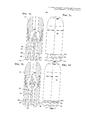
Ниже приведено подробное описание иллюстративных вариантов выполнения изобретения со ссылкой на чертежи, на которых фиг. 1а-5d изображают пять различных вариантов выполнения дозирующего устройства согласно изобретению.The following is a detailed description of illustrative embodiments of the invention with reference to the drawings, in which FIG. 1a-5d depict five different embodiments of a metering device according to the invention.
ПОДРОБНОЕ ОПИСАНИЕ ИЗОБРЕТЕНИЯDETAILED DESCRIPTION OF THE INVENTION
В нижеследующем описании номера позиций повторяются при обозначении одинаковых элементов в различных вариантах выполнения.In the following description, item numbers are repeated to refer to the same elements in various embodiments.
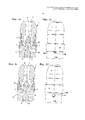
В первом варианте выполнения дозирующего устройства согласно изобретению (см. фиг. 1а-1d), на которых фиг. 1а и 1с изображают разрезы, соответствующие видам, показанным соответственно на фиг. 1b и 1d, имеется кожух 1 клапана, имеющий впускной проход 2 для проведения жидкости под давлением в виде газированного напитка из непоказанного источника в клапан, расположенный внутри кожуха 1. В камере 4 внутри кожуха 1 расположен корпус 3 клапана. Корпус 3 имеет головку 5 и шток 6. Камера 4 клапана содержит седло 7, на которое уплотнительное кольцо головки 5 корпуса клапана может опираться под действием жидкости под давлением, поступающей через проход 2. Видно, что шток 6 проходит от стороны головки 5, обращенной к седлу 7 клапана. Части клапана, обозначенные номерами 2, 3, 4, 5, 6 и 7 позиций, сформированы и расположены концентрическим образом вокруг оси 8 симметрии, проходящей в продольном направлении клапана.In a first embodiment of the metering device according to the invention (see FIGS. 1a-1d), in which FIG. 1a and 1c show sections corresponding to the views shown respectively in FIG. 1b and 1d, there is a
Как следует из фиг. 1а и 1с, шток 6 с возможностью скольжения установлен в отверстии 9 в нижней части кожуха 1, при этом отверстие 9 предназначено для направления корпуса 3 относительно кожуха 1 и камеры 4 с обеспечением его возвратно-поступательного перемещения вдоль оси 8.As follows from FIG. 1a and 1c, the
Кожух 1 выполнен с выпускными отверстиями 10, предназначенными для дозирования газированного напитка и расположенными под прямым углом к оси симметрии. На разрезах на фиг. 1а и 1с показаны два отверстия 10, однако возможно выполнение трех или более выпускных отверстий. Как вариант, дозирующее устройство согласно изобретению может быть выполнено с одним выпускным отверстием в рамках объема формулы изобретения.The
На фиг. 1а-1d корпус 3 клапана показан в состоянии, когда свободный конец 6а штока продвинут с переходом в открытое положение клапана, при котором отсутствует контакт между седлом 7 и головкой 5, с обеспечением тем самым свободного прохождения напитка из прохода 2 через камеру 4 и наружу через отверстия 10.In FIG. 1a-1d, the
Вышеописанные особенности дозирующего устройства по существу аналогичны особенностям известных устройств, например устройства, описанного в международном патентном документе №2011/069513. С помощью этого устройства дозирование осуществляется путем продвижения стакана или другого аналогичного средства вверх вокруг устройства до тех пор, пока дно стакана не войдет в контакт со свободным концом 6а штока, и последующего дальнейшего перемещения стакана до достижения корпусом 3 клапана положения, показанного на фиг. 1а-1d. Затем стакан заполняется снизу вверх.The above described features of the metering device are essentially similar to the features of known devices, for example, the device described in international patent document No. 2011/069513. With this device, dosing is carried out by moving the glass or other similar means upward around the device until the bottom of the glass comes into contact with the free end 6a of the stem, and then moving the glass further until the
В первом варианте выполнения изобретения имеется дросселирующее средство в виде кольца 20, приводимого в скольжение вручную. Кольцо 20 расположено снаружи кожуха 1 и установлено так, что оно может скользить вверх и вниз параллельно оси 8. На фиг. 1а и 1b кольцо 20 показано в положении дросселирования, в котором нижняя кромочная часть 20а кольца 20 частично закрывает отверстия 10 с уменьшением площади их поперечного сечения. Таким образом, газированный напиток, выходящий из отверстий 10, подвергается дросселированию и испытывает действие перепада давления с высвобождением при этом газа в газированном напитке. Степень пенообразования в газированном напитке может регулироваться путем перемещения кольца 20 вверх и вниз с обеспечением закрытия большей или меньшей части отверстий 10. При необходимости меньшей степени пенообразования кольцо 20 перемещается скольжением к его самому верхнему положению, показанному на фиг. 1а и 1с, с открытием тем самым всей площади поперечного сечения отверстий 10.In a first embodiment of the invention, there is a throttling means in the form of a
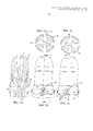
На фиг. 2а-2е изображен второй вариант выполнения дозирующего устройства согласно изобретению. Фиг. 2а изображает разрез по линии С-С на фиг. 2b, а фиг. 2d и 2е изображают разрезы по линиями А-А и В-В соответственно на фиг. 2b и 2с.In FIG. 2a-2e show a second embodiment of a metering device according to the invention. FIG. 2a is a section along line CC in FIG. 2b, and FIG. 2d and 2e show sections along lines AA and BB, respectively in FIG. 2b and 2c.
В данном варианте выполнения дросселирующее средство представляет собой поворотное кольцо 30 с проемами 31. Благодаря повороту кольца 30 вручную проемы 31 могут быть расположены напротив четырех выпускных отверстий 10 с созданием тем самым наименьшего возможного пенообразования при открытии корпуса 3 клапана для прохождения потока через клапан (см. фиг. 2а). При повороте кольца 30 площади, доступные для напитка, проходящего через отверстия 10, уменьшаются с увеличением тем самым перепада давления и повышением пенообразования в выходящем напитке.In this embodiment, the throttling means is a
В непоказанной модификации второго варианта выполнения, изображенного на фиг. 2а-2е, проемы могут иметь меньший диаметр или другую форму по сравнению с отверстиями 10. В частности, проемы с различными диаметрами могут быть распределены по периферии кольца 30 с обеспечением возможности использования заданных площадей поперечных сечений путем их расположения напротив отверстий 10 без необходимости в выполнении тонкой регулировки перекрытия между проемами 31 и отверстиями 10, как показано на фиг. 2с и 2е.In a modification not shown of the second embodiment of FIG. 2a-2e, the openings may have a smaller diameter or other shape than the
Кроме того, вышерассмотренный вариант выполнения может быть выполнен с выемками или отметками 32, расположенными на кольце 30 и указывающими на конкретные степени ограничения поперечного сечения потока, что облегчает настройку до выполнения дозирования конкретного напитка. Это особенно важно в случае переключения между различными сортами пива.In addition, the above embodiment can be made with recesses or marks 32 located on the
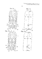
На фиг. 3а-3d изображен третий вариант выполнения дозирующего устройства согласно изобретению, причем фиг. 3а и 3b изображают разрезы, соответствующие видам, показанным соответственно на фиг. 3с и 3d. В данном случае дросселирующие средства выполнены в виде четырех дросселирующих элементов 40, установленных в отверстиях 41 в нижней части кожуха 1, по одному у каждого выпускного отверстия 10. Каждый элемент 40 может быть независимо перемещен параллельно оси 8 из нерабочего положения, показанного на фиг. 3а и 3с, в рабочее положение, показанное на фиг. 3b и 3d. В рабочем положении элементы 40 частично ограничивают поток, проходящий через отверстия 10, что приводит к повышению пенообразования, когда напиток выходит из отверстий 10. Элементы 40 удерживаются в отверстиях 41 благодаря трению, при этом эффект пенообразования может быть изменен вследствие скольжения одного или двух дросселирующих элементов с обеспечением частичного или полного закрытия проточных каналов у соответствующих выпускных отверстий 10.In FIG. 3a-3d illustrate a third embodiment of a metering device according to the invention, wherein FIG. 3a and 3b show sections corresponding to the views shown in FIG. 3c and 3d. In this case, the throttling means are made in the form of four throttling
На некоторых из рассмотренных выше чертежей кожух 1 изображен в виде узла, выполненного из двух частей, соединенных винтовым соединением для сборки, однако с точки зрения функционирования кожух 1 следует рассматривать как единый блок.In some of the above drawings, the
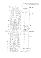
На фиг. 4а-4d изображен четвертый вариант выполнения дозирующего устройства согласно изобретению, причем фиг. 4а и 4b изображают разрезы, соответствующие видам, показанным соответственно на фиг. 4с и 4d. В данном случае дросселирующие средства образованы кожухом, выполненным из двух частей 51, 52: верхней части 51 для присоединения к источнику газированного напитка и нижней части 52, содержащей седло клапана и выпускные отверстия 50. Камера 54 клапана выполнена в виде полости, образованной при объединении частей 51 и 52.In FIG. 4a-4d show a fourth embodiment of a metering device according to the invention, wherein FIG. 4a and 4b show sections corresponding to the views shown in FIG. 4c and 4d. In this case, the throttling means are formed by a casing made of two
В четвертом варианте выполнения изобретения верхняя часть 51 образует юбку 51а, в которой с возможностью скольжения расположена нижняя часть 52. Таким образом, нижний периферический край 51b юбки 51 может действовать в качестве дросселирующего средства. На фиг. 4а и 4с показано нерабочее положение, в котором отверстия 50 полностью открыты и напиток может беспрепятственно выходить. На фиг. 4b и 4d показано рабочее положение дросселирующего средства, в котором край 51b юбки частично закрывает отверстия 50, что приводит к усилению эффекта пенообразования. Верхняя часть 51 удерживается благодаря трению между внутренней стороной юбки 51а и наружной стороной нижней части 52. Как вариант, для соединения верхней и нижней частей 51 и 52 может быть выполнена винтовая резьба (не показана) или защелкивающееся соединение.In a fourth embodiment of the invention, the
На фиг. 5а-5d изображен пятый вариант выполнения дозирующего устройства согласно изобретению, причем фиг. 5а и 5b изображают разрезы, соответствующие видам, показанным соответственно на фиг. 5с и 5d. Особенность данного варианта выполнения заключается в том, что кожух 61 выполнен укороченным, а выпускное отверстие или отверстия 60 образовано/образованы зазором между торцевой поверхностью 61а кожуха 61 и расширенным дисковидным концом 67 штока 66 корпуса 63 клапана. Дисковидный конец 67 проходит поперек отверстия центрального канала 62 в кожухе 61 и поперек торцевой поверхности 61а. В этом случае жидкий напиток проходит через канал 62 и между поверхностью 61а и концом 67 через отверстия 60.In FIG. 5a-5d show a fifth embodiment of a metering device according to the invention, wherein FIG. 5a and 5b are sectional views corresponding to the views shown respectively in FIG. 5c and 5d. A feature of this embodiment is that the
В данном случае дросселирующее средство образовано регулирующими штырями 68, которые фрикционно установлены в отверстиях, выполненных в конце 67. Перемещение штырей 68 вверх и вниз относительно конца 67 обеспечивает соответственно ослабление и усиление эффекта пенообразования, создаваемого дозирующим устройством согласно изобретению.In this case, the throttling means is formed by control pins 68, which are frictionally mounted in the holes made at the
Claims (17)
Applications Claiming Priority (2)
| Application Number | Priority Date | Filing Date | Title |
|---|---|---|---|
| DKPA201370775 | 2013-12-16 | ||
| DKPA201370775 | 2013-12-16 |
Publications (3)
| Publication Number | Publication Date |
|---|---|
| RU2014151126A RU2014151126A (en) | 2016-07-10 |
| RU2014151126A3 RU2014151126A3 (en) | 2018-06-19 |
| RU2664373C2 true RU2664373C2 (en) | 2018-08-16 |
Family
ID=52023388
Family Applications (1)
| Application Number | Title | Priority Date | Filing Date |
|---|---|---|---|
| RU2014151126A RU2664373C2 (en) | 2013-12-16 | 2014-12-16 | Device for dispensing carbonated beverage and method of dispensing carbonated beverage |
Country Status (3)
| Country | Link |
|---|---|
| EP (1) | EP2883833B1 (en) |
| PL (1) | PL2883833T3 (en) |
| RU (1) | RU2664373C2 (en) |
Families Citing this family (1)
| Publication number | Priority date | Publication date | Assignee | Title |
|---|---|---|---|---|
| US20200360875A1 (en) | 2019-05-14 | 2020-11-19 | Sodastream Industries Ltd. | Carbonation machine and a gas canister for a carbonation machine |
Citations (3)
| Publication number | Priority date | Publication date | Assignee | Title |
|---|---|---|---|---|
| GB2218357A (en) * | 1988-05-04 | 1989-11-15 | Anthony Frederick Delicata | Draught beer dispensing head |
| GB2252098A (en) * | 1990-12-15 | 1992-07-29 | Whitbread & Co Plc | Dispensing nozzle with cut-off valve |
| WO2011069513A1 (en) * | 2009-12-11 | 2011-06-16 | Jens Ksa Holding Aps | Apparatus for dispensing a pressurised liquid |
-
2014
- 2014-12-16 RU RU2014151126A patent/RU2664373C2/en not_active IP Right Cessation
- 2014-12-16 EP EP14198164.7A patent/EP2883833B1/en not_active Not-in-force
- 2014-12-16 PL PL14198164T patent/PL2883833T3/en unknown
Patent Citations (3)
| Publication number | Priority date | Publication date | Assignee | Title |
|---|---|---|---|---|
| GB2218357A (en) * | 1988-05-04 | 1989-11-15 | Anthony Frederick Delicata | Draught beer dispensing head |
| GB2252098A (en) * | 1990-12-15 | 1992-07-29 | Whitbread & Co Plc | Dispensing nozzle with cut-off valve |
| WO2011069513A1 (en) * | 2009-12-11 | 2011-06-16 | Jens Ksa Holding Aps | Apparatus for dispensing a pressurised liquid |
Also Published As
| Publication number | Publication date |
|---|---|
| RU2014151126A (en) | 2016-07-10 |
| EP2883833A1 (en) | 2015-06-17 |
| EP2883833B1 (en) | 2016-07-27 |
| RU2014151126A3 (en) | 2018-06-19 |
| PL2883833T3 (en) | 2017-08-31 |
Similar Documents
| Publication | Publication Date | Title |
|---|---|---|
| US4720076A (en) | Dispense tap | |
| US3966091A (en) | Carbonated beverage dispenser having diffuser assembly | |
| US5299715A (en) | Syrup dosing valve for use in installation for the preparation of flavored carbonated beverages | |
| US3341132A (en) | Spout diverter valve | |
| US4138092A (en) | Tap for dispensing carbonated beverages | |
| US3426798A (en) | Resilient seat cup with fins | |
| CN102971221A (en) | Dispensing unit and method for dispensing a liquid under pressure | |
| US2820604A (en) | Valve with adjustable opening | |
| CN101888966B (en) | Dual function dispensing head for carbonated beverage | |
| EP1786722B1 (en) | Beverage dispensing tap with spouts for the liquid and the foam | |
| US20050051214A1 (en) | Valve assembly for pressurized fluid vessel | |
| US10358332B2 (en) | Filling device | |
| US2167123A (en) | Filler valve | |
| CN1997584A (en) | A dispenser tap | |
| US10259697B2 (en) | Filling device | |
| RU2664373C2 (en) | Device for dispensing carbonated beverage and method of dispensing carbonated beverage | |
| JP6716414B2 (en) | Water discharge parts and water discharge device | |
| US3289948A (en) | Electric remote dispenser valve | |
| US4336896A (en) | Electrically controlled in-line dispensing faucet | |
| US3277924A (en) | Flow regulator particularly adapted for soft drink mixing and dispensing apparatus | |
| US20050236435A1 (en) | Sanitary faucet with improved flow restriction feature and foam control feature | |
| US1661431A (en) | Mixing valve | |
| JP7368588B2 (en) | pressure valve for liquids | |
| MXPA05004829A (en) | Sanitary faucet with improved flow restriction feature and foam control feature. | |
| US3322151A (en) | Fluid mixing valve having a flow metering insert |
Legal Events
| Date | Code | Title | Description |
|---|---|---|---|
| MM4A | The patent is invalid due to non-payment of fees |
Effective date: 20201217 |