RU2658867C2 - Control peripheral post of railway field devices provided with means to facilitate the extraction of the control modules - Google Patents
Control peripheral post of railway field devices provided with means to facilitate the extraction of the control modules Download PDFInfo
- Publication number
- RU2658867C2 RU2658867C2 RU2016112158A RU2016112158A RU2658867C2 RU 2658867 C2 RU2658867 C2 RU 2658867C2 RU 2016112158 A RU2016112158 A RU 2016112158A RU 2016112158 A RU2016112158 A RU 2016112158A RU 2658867 C2 RU2658867 C2 RU 2658867C2
- Authority
- RU
- Russia
- Prior art keywords
- locking
- control modules
- support frame
- centralization
- bar
- Prior art date
Links
Images


Classifications
-
- H—ELECTRICITY
- H05—ELECTRIC TECHNIQUES NOT OTHERWISE PROVIDED FOR
- H05K—PRINTED CIRCUITS; CASINGS OR CONSTRUCTIONAL DETAILS OF ELECTRIC APPARATUS; MANUFACTURE OF ASSEMBLAGES OF ELECTRICAL COMPONENTS
- H05K7/00—Constructional details common to different types of electric apparatus
- H05K7/14—Mounting supporting structure in casing or on frame or rack
- H05K7/1401—Mounting supporting structure in casing or on frame or rack comprising clamping or extracting means
- H05K7/1402—Mounting supporting structure in casing or on frame or rack comprising clamping or extracting means for securing or extracting printed circuit boards
- H05K7/1408—Mounting supporting structure in casing or on frame or rack comprising clamping or extracting means for securing or extracting printed circuit boards by a unique member which latches several boards, e.g. locking bars
-
- B—PERFORMING OPERATIONS; TRANSPORTING
- B61—RAILWAYS
- B61L—GUIDING RAILWAY TRAFFIC; ENSURING THE SAFETY OF RAILWAY TRAFFIC
- B61L27/00—Central railway traffic control systems; Trackside control; Communication systems specially adapted therefor
-
- H—ELECTRICITY
- H05—ELECTRIC TECHNIQUES NOT OTHERWISE PROVIDED FOR
- H05K—PRINTED CIRCUITS; CASINGS OR CONSTRUCTIONAL DETAILS OF ELECTRIC APPARATUS; MANUFACTURE OF ASSEMBLAGES OF ELECTRICAL COMPONENTS
- H05K7/00—Constructional details common to different types of electric apparatus
- H05K7/14—Mounting supporting structure in casing or on frame or rack
- H05K7/1422—Printed circuit boards receptacles, e.g. stacked structures, electronic circuit modules or box like frames
- H05K7/1424—Card cages
-
- H—ELECTRICITY
- H05—ELECTRIC TECHNIQUES NOT OTHERWISE PROVIDED FOR
- H05K—PRINTED CIRCUITS; CASINGS OR CONSTRUCTIONAL DETAILS OF ELECTRIC APPARATUS; MANUFACTURE OF ASSEMBLAGES OF ELECTRICAL COMPONENTS
- H05K7/00—Constructional details common to different types of electric apparatus
- H05K7/14—Mounting supporting structure in casing or on frame or rack
- H05K7/1462—Mounting supporting structure in casing or on frame or rack for programmable logic controllers [PLC] for automation or industrial process control
- H05K7/1474—Mounting of modules, e.g. on a base or rail or wall
Landscapes
- Engineering & Computer Science (AREA)
- Microelectronics & Electronic Packaging (AREA)
- Automation & Control Theory (AREA)
- Mechanical Engineering (AREA)
- Train Traffic Observation, Control, And Security (AREA)
- Electric Propulsion And Braking For Vehicles (AREA)
- Fittings On The Vehicle Exterior For Carrying Loads, And Devices For Holding Or Mounting Articles (AREA)
Abstract
Description
[0001] Настоящее изобретение относится к области техники, связанной с системами управления железнодорожными линиями, в частности к периферийному посту централизации для управления исполнительными устройствами железнодорожного пути.[0001] The present invention relates to the field of technology related to railway line control systems, in particular to a centralization peripheral station for controlling railway track actuators.
[0002] Как известно, системы железнодорожной блокировки и (или) сигнализации содержат главный пост централизации и один или несколько периферийных постов, оперативно подключенных к главному посту централизации. Периферийные посты централизации оперативно подключены, например, посредством электрических кабелей к ряду исполнительных устройств железнодорожного пути, таким как сигнальные устройства, переезды со шлагбаумом, маневровые устройства, стрелочные переводы, рельсовые цепи и т.д. В частности, на периферийном посту централизации устанавливают модули управления, подключенные к одному или нескольким соответствующим исполнительным устройствам. Указанные модули управления обычно помещают в специальные стойки. Зачастую используется модульная архитектура системы, это означает, что каждая стойка может вмещать несколько модулей управления, имеющих возможность извлечения или установки независимо один от другого, исходя из необходимого количества контролируемых исполнительных устройств, а также требований обслуживания и (или) масштабирования системы.[0002] As is known, railway blocking and / or signaling systems comprise a centralization main post and one or more peripheral posts operatively connected to the centralization main post. The centralization peripheral stations are operatively connected, for example, by means of electric cables to a number of railway track actuators, such as signaling devices, barriers, shunting devices, turnouts, rail circuits, etc. In particular, control modules connected to one or more respective actuators are installed at the centralization peripheral station. These control modules are usually placed in special racks. Often the modular architecture of the system is used, this means that each rack can accommodate several control modules that can be removed or installed independently of one another, based on the required number of controlled actuators, as well as the requirements for servicing and / or scaling the system.
[0003] В связи с этим недостаток периферийного поста централизации на известном уровне техники обусловлен тем, что извлечение и вставка модулей управления в соответствующие установочные места, предусмотренные в стойке, являются достаточно сложными операциями и требуют использования инструментов, которые могут быть утеряны или не всегда быть под рукой. Действительно, обычно каждый модуль управления крепится на соответствующем установочном месте, предусмотренном в стойке, посредством нескольких винтов, откручиваемых (или закручиваемых), чтобы извлечь (или вставить) один модуль в стойку. Это занимает достаточно длительное время, особенно когда необходимо извлечь и (или) вставить в стойку несколько модулей управления.[0003] In this regard, the disadvantage of the peripheralization centralization post in the prior art is due to the fact that the removal and insertion of control modules into the corresponding mounting positions provided in the rack are quite complicated operations and require the use of tools that may or may not be lost at hand. Indeed, typically each control module is secured to an appropriate mounting location provided in the rack by means of several screws that are loosened (or tightened) to remove (or insert) one module in the rack. This takes quite a long time, especially when it is necessary to remove and / or insert several control modules into the rack.
[0004] Главная цель настоящего изобретения состоит в предложении периферийного поста централизации для управления исполнительными устройствами железнодорожного пути, позволяющего устранить или по крайней мере частично минимизировать вышеперечисленные недостатки, существующие на известном уровне техники.[0004] The main objective of the present invention is to propose a centralization peripheral station for controlling railway track actuators, which makes it possible to eliminate or at least partially minimize the above disadvantages existing in the prior art.
[0005] Эта и другие цели достигаются посредством предложения периферийного поста централизации для управления исполнительными устройствами железнодорожного пути, имеющего общий вид, определяемый п. 1 формулы изобретения, и конкретные варианты исполнения, раскрытые в зависимых пунктах формулы изобретения.[0005] This and other objectives are achieved by proposing a peripheral centralization post for controlling the actuators of the railway, having the general form defined by
[0006] Предметом настоящего изобретения также является система железнодорожной сигнализации и (или) блокировки, заявленная в п. 8 формулы изобретения.[0006] The subject of the present invention is also a railway signaling and / or blocking system as claimed in claim 8.
[0007] Изобретение будет лучше понято из следующего подробного описания его вариантов исполнения, приводимого в качестве примера и поэтому не носящего ограничительного характера, со ссылкой на прилагаемые чертежи, где:[0007] The invention will be better understood from the following detailed description of its embodiments, given as an example and therefore not limiting, with reference to the accompanying drawings, where:
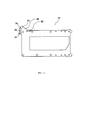
- на Фиг. 1 показан вид спереди в аксонометрии периферийного поста централизации, содержащего стойку, вмещающую множество модулей управления исполнительными устройствами железнодорожного пути, причем стойка содержит монтажную раму и опорную раму;- in FIG. 1 shows a front view in a perspective view of a peripheral centralization station comprising a rack containing a plurality of control modules for railway track actuators, the rack comprising a mounting frame and a support frame;
- на Фиг. 2 показан вид сзади в аксонометрии монтажной рамы, изображенной на Фиг. 1;- in FIG. 2 is a rear perspective view of the mounting frame shown in FIG. one;
- на Фиг. 3 показан вид спереди в аксонометрии опорной рамы, изображенной на Фиг. 1;- in FIG. 3 is a front perspective view of the support frame shown in FIG. one;
- на Фиг. 4 показан вид сбоку детали опорной рамы, изображенной на Фиг. 1, где, в частности, показан вид в разрезе планки, предотвращающей извлечение модулей, в первом положении;- in FIG. 4 is a side view of a detail of the support frame shown in FIG. 1, where, in particular, is shown a sectional view of a bar preventing the removal of modules in a first position;
- на Фиг. 5 показан вид сбоку тех же элементов, что изображены на Фиг. 4, а планка, предотвращающая извлечение, показана во втором положении;- in FIG. 5 shows a side view of the same elements as shown in FIG. 4, and an anti-removal bar is shown in a second position;
- на Фиг. 6 показан вид сбоку, сходный с Фиг. 4 и 5, где планка, предотвращающая извлечение, и некоторые дополнительные элементы, показанные на предыдущих чертежах, отсутствуют;- in FIG. 6 is a side view similar to FIG. 4 and 5, where the strip preventing the removal and some additional elements shown in the previous drawings are missing;
- на Фиг. 7 показан вид спереди части опорной рамы в увеличенном масштабе, представленной на Фиг. 1, где частично показана планка, предотвращающая извлечение модулей, изображенная на Фиг. 4 и 5;- in FIG. 7 is an enlarged front view of a portion of the support frame shown in FIG. 1, which partially shows the module removal prevention bar shown in FIG. 4 and 5;
- на Фиг. 8 показан вид спереди в аксонометрии модуля управления.- in FIG. 8 is a front perspective view of a control module.
[0008] В целом на прилагаемых чертежах эквивалентные или похожие элементы обозначены одинаковыми номерами ссылок. Однако в некоторых случаях, отдельно выделенных в последующем описании, для большей ясности описания некоторые эквивалентные или похожие элементы также могут быть обозначены различными номерами ссылок.[0008] In general, in the accompanying drawings, equivalent or similar elements are denoted by the same reference numbers. However, in some cases, highlighted separately in the following description, for clarity of description, some equivalent or similar elements may also be indicated by different reference numbers.
[0009] Также следует отметить, что термины «верхний», «нижний», «вертикальный» и «горизонтальный», используемые при последующем описании периферийного поста централизации или его части, следует понимать как относящиеся к периферийному посту централизации, установленному в нормальных условиях эксплуатации.[0009] It should also be noted that the terms “upper”, “lower”, “vertical” and “horizontal” used in the following description of a peripheral centralization post or part thereof, should be understood as referring to a peripheral centralization post established under normal operating conditions .
[0010] На Фиг. 1 показан периферийный пост 1 централизации, содержащий стойку 2, 3, вмещающую множество модулей управления 4, 5 исполнительными устройствами железнодорожного пути. Очевидно, что в зависимости от количества контролируемых исполнительных устройств периферийный пост 1 централизации может содержать большее количество стоек 2, 3 типа, показанного на Фиг. 1. Периферийный пост 1 централизации, изображенный на Фиг. 1, например, входит в систему железнодорожной сигнализации и (или) блокировки, состоящей из главного поста централизации (не показан) и ряда периферийных постов 1 централизации, причем главный пост централизации оперативно соединен с периферийными постами 1, а периферийные посты 1 подключены к исполнительным устройствам. Главный пост централизации выполнен с возможностью отправки логических сигналов управления железнодорожным транспортом к периферийным постам 1 централизации и с возможностью приема сигналов от периферийных постов централизации, содержащих информацию о состоянии контролируемых исполнительных устройств. Главный пост централизации соединен с периферийными постами 1 централизации посредством подходящей телекоммуникационной сети, такой как оптоволоконная сеть, работающей, например, по протоколу Ethernet.[0010] In FIG. 1, a centralization
[0011] Система железнодорожной сигнализации и (или) блокировки предназначена для управления одной или несколькими железнодорожными линиями, причем в настоящем описании термин «железнодорожная линия» означает любую линию, состоящую из одного или нескольких путей, подземных, наземных или смешанных, городского или пригородного сообщения, включая линии метро.[0011] The railway signaling and / or blocking system is intended to control one or more railway lines, moreover, in the present description, the term "railway line" means any line consisting of one or more tracks, underground, land or mixed, urban or suburban including metro lines.
[0012] Модули управления 4, 5 оперативно подключены или имеют возможность подключения, например, посредством электрических кабелей (не показаны) к нескольким исполнительным устройствам железнодорожного пути (не показаны на чертежах), таким как сигнальные устройства, переезды со шлагбаумом, маневровые устройства, стрелочные переводы, рельсовые цепи и т.д., для передачи в указанные устройства сигналов управления и (или) электропитания и предпочтительно для приема входных сигналов о состоянии от контролируемых устройств.[0012] The
[0013] В соответствии с целесообразным вариантом исполнения, стойка 2, 3 содержит монтажную раму 2 и опорную раму 3. Монтажная рама 2 (Фиг. 2) приспособлена для устойчивого крепления к опорной поверхности или к стене для установки. Такая рама 2 имеет переднюю сторону 6 и противоположную заднюю сторону 7, при этом на задней стороне 7 расположены первые разъемы 11, предназначенные для электрического подключения контактов электрических кабелей.[0013] According to an advantageous embodiment, the
[0014] Как показано на Фиг. 1, опорная рама 3 для модулей управления 4, 5 предназначена для размещения и крепления модулей 4, 5 и имеет возможность сцепления с монтажной рамой 2 посредством подтягивания опорной рамы 3 к монтажной раме 2 до достижения положения сцепления.[0014] As shown in FIG. 1, the
[0015] Как показано на Фиг. 2 и 3, в соответствии с целесообразным вариантом исполнения, монтажная рама 2 содержит основание 25 и по меньшей мере один вертикальный элемент 24, прикрепляемый к основанию 25, выступающему относительно вертикального элемента с передней стороны 6 монтажной рамы 2. В соответствии с одним из вариантов исполнения, указанный вертикальный элемент 24 имеет, как правило, поперечное сечение U-образной или С-образной формы. Предпочтительно, чтобы основание 25 имело плоскую форму и позволяло крепить монтажную раму 2 к съемному полу. В показанном конкретном примере монтажная рама 2 снабжена двумя вертикальными элементами 24, соединенными сверху плоской перекладиной 24.[0015] As shown in FIG. 2 and 3, in accordance with a suitable embodiment, the
[0016] В положении сцепления монтажной рамы 2 и опорной рамы 3 опорную раму 3 накладывают на основание 25. Предпочтительно, чтобы основание 25 имело ограничительные элементы 27, предназначенные для стабилизации положения сцепления. Например, в соответствии с одним из вариантов исполнения, опорная удерживающая рама 3 для модулей управления 4,5 снизу может быть оснащена несколькими колесами 37, например четырьмя колесами 37, предпочтительно изготовленными из фторопласта. В таком варианте исполнения ограничительные элементы 27 основания 25 представляют собой углубления 27, предназначенные по меньшей мере для частичной вставки колес 37, чтобы обеспечить подтягивание опорной рамы 3 к монтажной раме 2, при этом колеса накладываются на основание 25, что позволяет стягивать две рамы 4, 5 одну к другой до тех пор, пока колеса 37 не войдут в соответствующие углубления.[0016] In the engagement position of the
[0017] В соответствии с одним из вариантов исполнения, основание 25 снабжено одним или несколькими сквозными отверстиями 26, предусмотренными для прохода соединительных кабелей к исполнительным устройствам железнодорожного пути.[0017] In accordance with one embodiment, the
[0018] Как показано на Фиг. 3, в соответствии с целесообразным вариантом исполнения, опорная рама 3 содержит множество установочных мест 30, предназначенных для установки модулей управления 4, 5. Целесообразно, чтобы установочные места 30 сформировали решетку из установочных мест, расположенных в несколько рядов, например в восемь рядов, как в случае опорной рамы 3, показанной на прилагаемых чертежах.[0018] As shown in FIG. 3, in accordance with a suitable embodiment, the
[0019] Предпочтительно, чтобы опорная рама 3 содержала два боковых вертикальных элемента 31, выполненных в виде двух боковых вертикальных пластин 31, удерживаемых вместе по меньшей мере одним поперечным элементом 32 или, что более целесообразно, несколькими поперечными элементами 32. Предпочтительно, чтобы вертикальные пластины 31 имели множество отверстий 34 и были выполнены из металла, например из алюминия. Целесообразно, чтобы между вертикальными пластинами 31 в каждом ряду установочных мест 30 проходило несколько стержней 35, разделяющих установочные места 30 по вертикали и служащих опорой для модулей управления 4, 5. Предпочтительно, чтобы для разделения установочных мест 30 по горизонтали было предусмотрено несколько вертикальных разделительных пластин 39, 41, пересекаемых стержнями 35. В соответствии с целесообразным вариантом исполнения, в каждом ряду установочных мест 30 в качестве разделительных пластин 39, 41 используют несколько пластин 39 первого типа, иначе называемых промежуточными пластинами 39, и пару пластин 41 второго типа, иначе называемых концевыми пластинами 41, между которыми располагают промежуточные пластины 39. На Фиг. 6 показан целесообразный вариант исполнения одной из пластин 41 второго типа, имеющей конструкцию, более подробно раскрытую далее. Предпочтительно, чтобы между двумя последовательными рядами установочных мест 30 опорная рама 3 содержала по меньшей мере одну наклонную панель 38, например, из металла, служащую для отвода тепла, выделяемого при работе модулями управления 4, 5, к задней поверхности опорной рамы 3.[0019] Preferably, the
[0020] Модули управления 4, 5, один из них показан на Фиг. 8, содержат вторые разъемы 12, соединяющиеся электрически или имеющие возможность электрического соединения с соответствующими первыми разъемами 11 монтажной рамы 2 в положении сцепления рам 2, 3.[0020] The
[0021] Как показано на Фиг. 8, предпочтительно, чтобы модули управления 4, 5 имели контейнерный корпус 50 с передней поверхностью 51 и задней поверхностью 52. В соответствии с целесообразным вариантом исполнения, модули управления 4, 5 имеют ручки 53 для захвата, выступающие на передней поверхности 51. Контейнерный корпус 50 вмещает одну или несколько монтажных плат, например платы ввода, платы вывода и оперативные платы. Такие монтажные платы могут предназначаться для обработки и преобразования сигналов, например, чтобы сформировать выходные сигналы требуемой мощности для управления и (или) электропитания исполнительных устройств железнодорожного пути. С этой целью можно предусмотреть обрабатывающие модули 4, предназначенные для обработки сигналов, и отдельные модули 5 для преобразования сигналов, оперативно подключаемые к соответствующему обрабатывающему модулю 4. Обрабатывающие модули 4 оперативно соединены с главным постом централизации и предназначены для управления преобразующими модулями 5, чтобы те в свою очередь контролировали исполнительные устройства железнодорожного пути. Каждая пара, состоящая из обрабатывающего модуля 4 и соответствующего преобразующего модуля 5 представляет собой контроллер исполнительных устройств железнодорожного пути.[0021] As shown in FIG. 8, it is preferable that the
[0022] При наличии описанного выше различия в типах между обрабатывающими модулями 4 и преобразующими модулями 5 очевидно, что необходимо выполнить прокладку кабелей только от преобразующих модулей 5 к исполнительным устройствам железнодорожного пути. Кроме того, в этом случае обрабатывающие модули 4 могут быть подключены к соответствующему преобразующему модулю 5 через шинную монтажную плату (не показана на чертежах), расположенную в нижней части установочных мест 30 в опорной раме 3. С этой целью предпочтительно, чтобы обрабатывающие модули 4 и преобразующие модули 5 имели интерфейсный разъем (не показан на чертежах), предусматриваемый для подключения модулей управления 4, 5 к шинной плате.[0022] Given the type differences described above between the
Возвращаясь к Фиг. 1, в соответствии с целесообразным вариантом исполнения, опорная рама 3 содержит по меньшей мере один ряд модулей управления 4, 5, состоящий из модулей управления, оперативно подключенных или имеющих возможность подключения к исполнительным устройствам. Предпочтительно, чтобы опорная рама 3 содержала несколько рядов модулей управления 4, 5, расположенных в вертикальных стойках. Иными словами, предпочтительно, чтобы опорная рама 3 содержала несколько рядов модулей управления 4, 5, состоящих из совокупности модулей управления, выровненных по горизонтали или один относительно другого. В примере, показанном на Фиг. 1, каждый ряд установочных мест 30 опорной рамы 3 приспособлен для размещения ряда модулей управления 4, 5, состоящего из восьми модулей управления 4, 5. В частности, в примере, показанном на Фиг. 1, обрабатывающие модули 4 занимают четыре центральных установочных места в ряду, а преобразующие модули 5 - оставшиеся четыре боковых установочных места. Целесообразно, чтобы опорная рама 3 имела по меньшей мере одну предотвращающую извлечение планку 60, или блокирующую планку 60, расположенную на передней стороне 61 опорной рамы 3. В примере передняя сторона 61 опорной рамы 3 является той стороной рамы, где расположены передние поверхности 51 модулей управления 4, 5, установленных в опорной раме. В соответствии с целесообразным вариантом исполнения опорная рама 3 содержит несколько предотвращающих извлечение планок 60, в примере восемь планок 60, относящихся к соответствующему ряду модулей управления 4, 5 или соответствующему ряду установочных мест 30, в последнем случае имеется в виду рама 3 без установленных на места 30 модулей управления. Каждая планка 60, предотвращающая извлечение модулей, приспособлена для того, чтобы на выбор ее можно было установить в положение извлечения (Фиг. 4) или в положение блокировки (Фиг. 5). В положении извлечения планка 60 располагается таким образом, чтобы обеспечить возможность извлечения модулей управления соответствующего ряда с передней стороны 61 рамы 3. В положении блокировки планка 60 устанавливается перед модулями управления 4, 5 соответствующего ряда модулей управления, чтобы предотвратить извлечение модулей управления этого ряда с передней стороны 61 опорной рамы.Returning to FIG. 1, in accordance with a suitable embodiment, the
[0023] В соответствии с целесообразным вариантом исполнения каждая предотвращающая извлечение планка 60 представляет собой планку, имеющую возможность перемещения по выбору между верхней позицией извлечения (Фиг. 4) и нижней позицией блокировки (Фиг. 5), соответствующих вышеуказанным положениям извлечения и блокировки.[0023] According to an advantageous embodiment, each
[0024] Как показано на Фиг. 4-6, в соответствии с целесообразным вариантом исполнения, опорная рама 3 содержит блокирующие элементы 71, 72, предусмотренные для блокировки каждой планки 60 по выбору в положениях извлечения или блокировки. Предпочтительно, чтобы блокирующие элементы 71, 72 располагались с двух противоположных концов 62 (Фиг. 1 и 3) каждой планки 60. Однако, в соответствии с менее предпочтительным альтернативным вариантом исполнения, поскольку он обеспечивает менее эффективную блокировку планки 60, блокирующие элементы 71, 72 также могут располагаться только с одного конца 62 планки 60. Как показано на Фиг. 7, в соответствии с целесообразным вариантом исполнения, каждая планка 60 имеет пару блокировочных штырей 71 с переменной толщиной (на Фиг. 7 показан только один из блокировочных штырей 71, а другой штырь 71, расположенный на противоположном конце планки 60, не показан, поскольку на Фиг. 7 показана лишь часть этой планки). Блокировочные штыри 71 установлены с возможностью скольжения на соответствующем конце 62 планки, предотвращающей извлечение модулей. Как показано на Фиг. 6 и 7, каждый блокировочный штырь 71 имеет часть 73 с относительно большим поперечным сечением и часть 74 с относительно малым поперечным сечением. В соответствии с целесообразным вариантом исполнения, часть 74 блокировочного штыря с меньшим поперечным сечением предназначена для сцепления с центральной направляющей частью 75 соответствующего блокировочного щелевого отверстия 72, выполненного в одной из концевых пластин 41 или, что более предпочтительно, в выступающей части 42 (Фиг. 6) такой пластины 41. В частности, часть 74 с меньшим поперечным сечением предназначена для сцепления с центральной направляющей частью 75 блокировочного щелевого отверстия для обеспечения сдвига блокировочного штыря во время перемещения планки 60, предотвращающей извлечение модулей. Часть 73 блокировочного штыря с большим поперечным сечением предназначена, в свою очередь, для сцепления с парой концевых частей 76 блокировочного щелевого отверстия 72, несколько расширенных по сравнению с направляющей частью 75. Более конкретно, часть 73 с большим поперечным сечением предназначена для сцепления с расширенными концевыми частями 76 блокировочного щелевого отверстия для блокировки планки 60, предотвращающей извлечение, в положениях извлечения и блокировки.[0024] As shown in FIG. 4-6, in accordance with a suitable embodiment, the
[0025] Вновь обратимся к Фиг. 7, в соответствии с целесообразным вариантом исполнения, каждая предотвращающая извлечение планка 60 имеет пару концевых стопорных отверстий 81, причем каждое из них относится к соответствующему блокировочному штырю 71 (на Фиг. 7 показано только одно концевое стопорное отверстие 81). Кроме того, предпочтительно, чтобы каждый блокировочный штырь 71 был снабжен концевым стопорным элементом 82, выступающим из блокировочного штыря и входящим в концевое стопорное отверстие 81. Каждое концевое стопорное отверстие 81 и соответствующий выступающий концевой стопорный элемент 82 приспособлены для сцепления один с другим, чтобы устанавливать для соответствующего блокировочного штыря 71 две противоположные конечные позиции блокировки. В соответствии с предпочтительным вариантом исполнения, выступающий концевой стопорный элемент 82 соединен посредством разъемного соединения с соответствующим блокировочным штырем 71. Например, концевой стопорный элемент 82 может ввинчиваться в блокировочный штырь 71 посредством такого инструмента, как универсальный гаечный ключ. Использование разъемного соединения концевого стопорного элемента 82 с блокировочным штырем 71 позволяет вставлять и извлекать блокировочный штырь 71 из соответствующего направляющего гнезда, предусмотренного в планке 60, существенно упрощая сборку и разборку планки 60, например, во время выполнения операций монтажа или демонтажа опорной рамы 3.[0025] Referring again to FIG. 7, in accordance with a suitable embodiment, each
Следует отметить, что каждая планка 60 устанавливается шарнирно, например, посредством пары шарнирных болтов 91 (Фиг. 4 и 5), выступающих по бокам планки 60 и соединенных с соответствующими шарнирными отверстиями 92 (Фиг. 6), выполненными в концевых пластинах 41. Иными словами, как видно из примера, представленного на Фиг. 4 и Фиг. 5, каждая предотвращающая извлечение планка 60 установлена шарнирно на петлях с возможностью поворота относительно неподвижной и заранее заданной оси вращения. Вновь обратимся к Фиг. 4 и Фиг. 5, в соответствии с целесообразным вариантом исполнения, неподвижная и заранее заданная ось вращения для каждой планки 60, предотвращающей извлечение, представляет собой горизонтальную ось.It should be noted that each
[0026] После описания конструкции периферийного поста 1 далее будет раскрыт способ извлечения модулей управления 4, 5 из ряда установочных мест 30 опорной рамы 3 на примере конкретного варианта исполнения, представленного на прилагаемых чертежах.[0026] After describing the design of the
[0027] Предположим, что предотвращающая извлечение планка 60, относящаяся к ряду установочных мест 30, изначально находится в положении блокировки (Фиг. 5). В этом положении планка 60 занимает нижнюю позицию блокировки, а два блокировочных штыря 71 планки 60 в большей степени выступают по бокам таким образом, что соответствующие части 73 с большим поперечным сечением сцепляются с соответствующими расширенными частями 76 блокировочных щелевых отверстий 72, чтобы обеспечить блокировку планки 60. В частности, в этом положении блокировочные штыри 71 занимают одну из конечных позиций блокировки, определяемых концевыми стопорными отверстиями 81 и соответствующими выступающими концевыми стопорными элементами 82. Для того чтобы перевести планку 60 из этого положения в верхнюю позицию извлечения, достаточно нажать, например, вручную на блокировочные штыри 71, чтобы высвободить штыри из расширенных концевых частей 76 отверстий 72 и перевести их в другое конечное положение блокировки, определяемое концевыми стопорными отверстиями 81 и выступающими концевыми стопорными элементами 82. В этом положении блокировочные штыри 71 выступают по бокам в меньшей степени, чем в положении блокировки. При этом планку 60 можно сдвигать, например, вручную путем перемещения частей 74 блокировочных штырей с меньшим поперечном сечением внутри центральных направляющих частей 75 блокировочных щелевых отверстий 75 до тех пор, пока планка, предотвращающая извлечение, не займет верхнюю позицию извлечения. Как только планка 60 займет верхнюю позицию извлечения, планку 60 можно заблокировать, вновь переведя блокировочные штыри 71 в конечную позицию блокировки, соответствующую положению блокировки. Иными словами, в верхнем положении извлечения планку 60 можно заблокировать, вытягивая блокировочные штыри до тех пор, пока не произойдет сцепления части 73 блокировочных штырей с большим поперечным сечением с другой расширенной концевой частью 76 блокировочных щелевых отверстий 72. Таким образом, планка 60 будет установлена в положение извлечения (Фиг. 4). В этом положении один или несколько модулей управления 4, 5 достаточно легко могут быть извлечены (или вставлены) из соответствующих установочных мест 30 предпочтительно с использованием соответствующих ручек 53 для захвата.[0027] Assume that the
[0028] Периферийный пост 1 централизации, раскрытый выше, позволяет устанавливать и извлекать множество модулей управления гораздо проще и быстрее по сравнению с техническими решениями, существующими на известном уровне техники и рассмотренными ранее, с помощью простой установки планки, предотвращающей извлечение, в соответствующее положение извлечения, не требуя отвинчивания или завинчивания множества крепежных винтов, служащих для крепления модулей управления в соответствующих установочных местах, предусмотренных в опорной раме.[0028] The centralization
[0029] Из приведенного описания можно понять, каким образом периферийный пост централизации рассмотренного выше типа позволяет достичь целей, указанных ранее со ссылкой на известный уровень техники.[0029] From the above description, it is possible to understand how the peripheral centralization post of the type discussed above allows achieving the goals indicated previously with reference to the prior art.
[0030] При условии понимания принципа изобретения детали производства и варианты исполнения могут быть существенно изменены относительного того, что описано и представлено исключительно в качестве примера, не накладывающего каких-либо ограничений, не отклоняясь от объема изобретения, заданного в прилагаемой формуле изобретения.[0030] Subject to an understanding of the principle of the invention, production details and embodiments can be substantially changed relative to what is described and presented solely as an example, without imposing any restrictions, without deviating from the scope of the invention defined in the attached claims.
Claims (17)
Applications Claiming Priority (3)
| Application Number | Priority Date | Filing Date | Title |
|---|---|---|---|
| IT000543A ITRM20130543A1 (en) | 2013-10-04 | 2013-10-04 | PERIPHERAL PLACE OF CONTROL OF ENTITY OF RAILWAY PIAZZALE WITH MEANS OF EASY EXTRACTION OF CONTROL MODULES |
| ITRM2013A000543 | 2013-10-04 | ||
| PCT/IT2014/000260 WO2015049709A2 (en) | 2013-10-04 | 2014-10-03 | Control peripheral post of railway field devices provided with means to facilitate the extraction of the control modules |
Publications (2)
| Publication Number | Publication Date |
|---|---|
| RU2016112158A RU2016112158A (en) | 2017-10-05 |
| RU2658867C2 true RU2658867C2 (en) | 2018-06-25 |
Family
ID=49725268
Family Applications (1)
| Application Number | Title | Priority Date | Filing Date |
|---|---|---|---|
| RU2016112158A RU2658867C2 (en) | 2013-10-04 | 2014-10-03 | Control peripheral post of railway field devices provided with means to facilitate the extraction of the control modules |
Country Status (9)
| Country | Link |
|---|---|
| US (1) | US9648772B2 (en) |
| EP (1) | EP3053422B1 (en) |
| BR (1) | BR112016007434B1 (en) |
| ES (1) | ES2659572T3 (en) |
| IT (1) | ITRM20130543A1 (en) |
| MA (1) | MA38940B1 (en) |
| PL (1) | PL3053422T3 (en) |
| RU (1) | RU2658867C2 (en) |
| WO (1) | WO2015049709A2 (en) |
Families Citing this family (2)
| Publication number | Priority date | Publication date | Assignee | Title |
|---|---|---|---|---|
| EP3056953A1 (en) * | 2015-02-11 | 2016-08-17 | Siemens Aktiengesellschaft | Self-contained field device used in automation technology for remote monitoring |
| JP6570318B2 (en) * | 2015-05-28 | 2019-09-04 | アズビル株式会社 | Board unit lock structure |
Citations (4)
| Publication number | Priority date | Publication date | Assignee | Title |
|---|---|---|---|---|
| DE2615682A1 (en) * | 1976-04-09 | 1977-10-13 | Siemens Ag | Lock for electronic and electromechanical insert assemblies - uses vertical movement for lock release against spring pressure |
| DE2615671A1 (en) * | 1976-04-09 | 1977-10-13 | Siemens Ag | Electronic insert assemblies locking device - has lock fastened on support and has elastic element pressing on insert edges |
| SU1300099A1 (en) * | 1985-06-17 | 1987-03-30 | Предприятие П/Я А-1836 | Support structure |
| US5128833A (en) * | 1991-03-26 | 1992-07-07 | Alcatel Network Systems, Inc. | Self-locking system for circuit board holding frames |
Family Cites Families (14)
| Publication number | Priority date | Publication date | Assignee | Title |
|---|---|---|---|---|
| US3926490A (en) * | 1973-04-18 | 1975-12-16 | Gte Automatic Electric Lab Inc | Locking bar for printed wiring card file |
| DE2757761A1 (en) * | 1977-12-23 | 1979-06-28 | Siemens Ag | Rack frame for electronic component mounting - has release spring attached to frame and rear side of locking rail over edge of component unit |
| US4418820A (en) * | 1981-10-23 | 1983-12-06 | Nagle Joseph J | Circuit board case |
| US4620756A (en) * | 1985-12-13 | 1986-11-04 | Motorola Computer Systems, Inc. | Printed wiring assembly insertion/extraction tool |
| US4964810A (en) * | 1989-12-27 | 1990-10-23 | Ncr Corporation | Retaining bar for printed wiring cards |
| US5735407A (en) * | 1995-10-03 | 1998-04-07 | North East Systems Associates, Inc. | Container for printed circuit boards |
| WO1998020150A1 (en) * | 1996-11-07 | 1998-05-14 | Kyowa Hakko Kogyo Co., Ltd. | Process for preparing cholesterol-lowering compound |
| US6049451A (en) * | 1996-11-14 | 2000-04-11 | Dell Usa, L.P. | Mounting rail retaining pin aperture |
| JP3862944B2 (en) * | 2000-07-28 | 2006-12-27 | 三菱電機株式会社 | Plug-in unit insertion / extraction mechanism |
| US7463494B2 (en) * | 2002-01-21 | 2008-12-09 | Pep West, Inc. | System for insertion and extraction of a printed circuit board module into and out of a subrack |
| US20030233855A1 (en) * | 2002-06-21 | 2003-12-25 | Rubin Pirveysian | Apparatus for securing moveable objects within a support rack |
| CN100489731C (en) * | 2005-09-30 | 2009-05-20 | 鸿富锦精密工业(深圳)有限公司 | Pin of cradle server |
| CN101965112A (en) * | 2009-07-22 | 2011-02-02 | 鸿富锦精密工业(深圳)有限公司 | Sliding rail fixing device |
| US8446720B2 (en) * | 2010-11-29 | 2013-05-21 | Hong Fu Jin Precision Industry (Shenzhen) Co., Ltd. | Mounting apparatus for expansion card |
-
2013
- 2013-10-04 IT IT000543A patent/ITRM20130543A1/en unknown
-
2014
- 2014-10-03 WO PCT/IT2014/000260 patent/WO2015049709A2/en active Application Filing
- 2014-10-03 RU RU2016112158A patent/RU2658867C2/en active
- 2014-10-03 US US15/026,758 patent/US9648772B2/en active Active
- 2014-10-03 BR BR112016007434-3A patent/BR112016007434B1/en active IP Right Grant
- 2014-10-03 EP EP14809996.3A patent/EP3053422B1/en active Active
- 2014-10-03 PL PL14809996T patent/PL3053422T3/en unknown
- 2014-10-03 MA MA38940A patent/MA38940B1/en unknown
- 2014-10-03 ES ES14809996.3T patent/ES2659572T3/en active Active
Patent Citations (4)
| Publication number | Priority date | Publication date | Assignee | Title |
|---|---|---|---|---|
| DE2615682A1 (en) * | 1976-04-09 | 1977-10-13 | Siemens Ag | Lock for electronic and electromechanical insert assemblies - uses vertical movement for lock release against spring pressure |
| DE2615671A1 (en) * | 1976-04-09 | 1977-10-13 | Siemens Ag | Electronic insert assemblies locking device - has lock fastened on support and has elastic element pressing on insert edges |
| SU1300099A1 (en) * | 1985-06-17 | 1987-03-30 | Предприятие П/Я А-1836 | Support structure |
| US5128833A (en) * | 1991-03-26 | 1992-07-07 | Alcatel Network Systems, Inc. | Self-locking system for circuit board holding frames |
Also Published As
| Publication number | Publication date |
|---|---|
| EP3053422A2 (en) | 2016-08-10 |
| MA38940A1 (en) | 2016-08-31 |
| BR112016007434A2 (en) | 2017-08-01 |
| BR112016007434B1 (en) | 2022-02-08 |
| US20160234956A1 (en) | 2016-08-11 |
| EP3053422B1 (en) | 2017-11-15 |
| US9648772B2 (en) | 2017-05-09 |
| MA38940B1 (en) | 2017-03-31 |
| WO2015049709A3 (en) | 2015-06-11 |
| PL3053422T3 (en) | 2018-05-30 |
| ES2659572T3 (en) | 2018-03-16 |
| WO2015049709A2 (en) | 2015-04-09 |
| ITRM20130543A1 (en) | 2015-04-05 |
| RU2016112158A (en) | 2017-10-05 |
Similar Documents
| Publication | Publication Date | Title |
|---|---|---|
| DE10052998A1 (en) | Mounting platform for electricity meter unit, has rapid coupling for connecting unit electrically and mechanically without tools; unit is moved parallel to platform to locking position | |
| RU2658867C2 (en) | Control peripheral post of railway field devices provided with means to facilitate the extraction of the control modules | |
| CN102035148B (en) | For having the functional unit of the low pressure panel of test position | |
| JP2011200113A (en) | Plug interlock device of circuit-breaker | |
| AU2022228111B2 (en) | Extractable structure for housing electronic components | |
| EP1356556B1 (en) | Power engineering distribution system for supplying electrical consumers | |
| AU2021463299A1 (en) | Withdrawable unit for a functional unit compartment of a low-voltage switchgear or controlgear | |
| RU2665161C2 (en) | Peripheral centralization post for control over the railway track actuators and the peripheral post installation method | |
| CN101931177B (en) | Low-voltage switch cabinet having 1/2M draw-out type functional units | |
| CN213535462U (en) | Thing frame is used in international trade logistics storage | |
| US3349288A (en) | Framework and connection system for removable electrical components | |
| US4631638A (en) | Box for holding circuit boards | |
| EP2082634A1 (en) | Power supply assembly | |
| EP1807915A1 (en) | A mounting system for a switchboard and a method for assembling the switchboard | |
| CN114080752A (en) | Support connector, solar panel connector attachable thereto and attachment system comprising support connector and solar panel connector | |
| CN213519771U (en) | Compact relay | |
| WO2020100033A1 (en) | Device for allowing correct mutual positioning of adjacent busbar modules | |
| WO2002039756A1 (en) | Retrofit patch and/or test panel | |
| CN217934696U (en) | Clamping structure based on subway traction equipment electric box | |
| EP1976084A2 (en) | Integrated system for first- and second-row air-break switches-disconnectors, with simplified maintenance, for railroad, tramway, light-rail, and subway power supplies | |
| CN213717520U (en) | Wiring rack in communication machine room | |
| CN112202075B (en) | Switch cabinet and switch cabinet installation method | |
| SU1504825A1 (en) | Electronic cabinet | |
| ITFI20000235A1 (en) | DEVICE FOR CONNECTION OF MODULAR PLUGS | |
| JPH0113493Y2 (en) |