RU2651925C1 - Atomizer of valve injector for internal combustion engine and method of its assembly - Google Patents
Atomizer of valve injector for internal combustion engine and method of its assembly Download PDFInfo
- Publication number
- RU2651925C1 RU2651925C1 RU2017126016A RU2017126016A RU2651925C1 RU 2651925 C1 RU2651925 C1 RU 2651925C1 RU 2017126016 A RU2017126016 A RU 2017126016A RU 2017126016 A RU2017126016 A RU 2017126016A RU 2651925 C1 RU2651925 C1 RU 2651925C1
- Authority
- RU
- Russia
- Prior art keywords
- valve
- atomizer
- assembly
- fuel
- internal combustion
- Prior art date
Links
Images
Classifications
-
- F—MECHANICAL ENGINEERING; LIGHTING; HEATING; WEAPONS; BLASTING
- F02—COMBUSTION ENGINES; HOT-GAS OR COMBUSTION-PRODUCT ENGINE PLANTS
- F02M—SUPPLYING COMBUSTION ENGINES IN GENERAL WITH COMBUSTIBLE MIXTURES OR CONSTITUENTS THEREOF
- F02M61/00—Fuel-injectors not provided for in groups F02M39/00 - F02M57/00 or F02M67/00
- F02M61/04—Fuel-injectors not provided for in groups F02M39/00 - F02M57/00 or F02M67/00 having valves, e.g. having a plurality of valves in series
- F02M61/08—Fuel-injectors not provided for in groups F02M39/00 - F02M57/00 or F02M67/00 having valves, e.g. having a plurality of valves in series the valves opening in direction of fuel flow
-
- F—MECHANICAL ENGINEERING; LIGHTING; HEATING; WEAPONS; BLASTING
- F02—COMBUSTION ENGINES; HOT-GAS OR COMBUSTION-PRODUCT ENGINE PLANTS
- F02M—SUPPLYING COMBUSTION ENGINES IN GENERAL WITH COMBUSTIBLE MIXTURES OR CONSTITUENTS THEREOF
- F02M61/00—Fuel-injectors not provided for in groups F02M39/00 - F02M57/00 or F02M67/00
- F02M61/16—Details not provided for in, or of interest apart from, the apparatus of groups F02M61/02 - F02M61/14
- F02M61/168—Assembling; Disassembling; Manufacturing; Adjusting
-
- F—MECHANICAL ENGINEERING; LIGHTING; HEATING; WEAPONS; BLASTING
- F02—COMBUSTION ENGINES; HOT-GAS OR COMBUSTION-PRODUCT ENGINE PLANTS
- F02M—SUPPLYING COMBUSTION ENGINES IN GENERAL WITH COMBUSTIBLE MIXTURES OR CONSTITUENTS THEREOF
- F02M61/00—Fuel-injectors not provided for in groups F02M39/00 - F02M57/00 or F02M67/00
- F02M61/16—Details not provided for in, or of interest apart from, the apparatus of groups F02M61/02 - F02M61/14
- F02M61/18—Injection nozzles, e.g. having valve seats; Details of valve member seated ends, not otherwise provided for
- F02M61/1886—Details of valve seats not covered by groups F02M61/1866 - F02M61/188
Abstract
Description
Изобретение относится к топливоподающим системам двигателей внутреннего сгорания (ДВС), а именно к электроуправляемым форсункам для впрыскивания топлива, подаваемого в них под высоким давлением, в камеру сгорания ДВС.The invention relates to fuel supply systems of internal combustion engines (ICE), and in particular to electrically controlled nozzles for injecting fuel supplied to them under high pressure into the combustion chamber of an internal combustion engine.
В большинстве случаев подача и распыливание топлива в ДВС осуществляются с помощью современной электронно управляемой топливоподающей аппаратуры аккумуляторного типа, в качестве исполнительного устройства которой используются электроуправляемые форсунки, в том числе форсунки с клапанными распылителями, обеспечивающие надлежащее распыливание топлива (Schmid Andreas, Experimental characterization of the two phase flow of a Modern, piezo activated hollow cone injector / Andreas Schmid: diss. eth NO. 20852, the degree of Doctor of Sciences. - Zurich. - 2012. - 166 p.), (Beatrice, C., Migliaccio, M., Montanaro, A., Fraioli, V. et al., "Experimental and Numerical Analysis of a High-Pressure Outwardly Opening Hollow Cone Spray Injector for Automotive Engines," SAE Technical Paper 2017-01-0840, 2017, doi: 10.4271/2017-01-0840).In most cases, the supply and atomization of fuel in the internal combustion engine are carried out using modern, electronically controlled fuel-supply equipment of the battery type, the actuating device of which is electrically controlled nozzles, including nozzles with valve atomizers, which ensure proper atomization of the fuel (Schmid Andreas, Experimental characterization of the two phase flow of a Modern, piezo activated hollow cone injector / Andreas Schmid: diss. eth NO. 20852, the degree of Doctor of Sciences. - Zurich. - 2012 .-- 166 p.), (Beatrice, C., Migliaccio, M ., Montanaro, A., Fraioli, V. et al., "Experimental and Numerical Analysis of a High-Press ure Outwardly Opening Hollow Cone Spray Injector for Automotive Engines, "SAE Technical Paper 2017-01-0840, 2017, doi: 10.4271 / 2017-01-0840).
В связи с тенденцией увеличения давления впрыскивания топлива повышаются требования к качеству распыливания топлива в камере сгорания ДВС, а именно должно быть обеспечено: во-первых, формирование высокорасходных кратковременных импульсов впрыскивания топлива; во-вторых, мелкость распыливания топлива; в-третьих, точность дозирования цикловой подачи. Последнее особенно важно для управления двигателем на холостом ходу, когда должна обеспечиваться минимальная топливоподача, одинаковая для каждого из цилиндров ДВС.In connection with the tendency to increase the fuel injection pressure, the requirements for the quality of fuel atomization in the combustion chamber of the internal combustion engine increase, namely, it must be ensured: firstly, the formation of high-consumption short-term fuel injection pulses; secondly, fineness of fuel atomization; thirdly, the accuracy of dosing cyclic feed. The latter is especially important for controlling the engine idling, when a minimum fuel supply should be ensured, the same for each of the ICE cylinders.
Известны форсунки с клапанными распылителями (пат. RU 2439362 C2, DE 19534445 С2, пат. RU 2244151 C2, пат. RU 2191284 C2, пат. RU 2538146 и пат. RU 2540347 C2), в которых клапан открывается по ходу течения топлива в процессе его впрыскивания. В них используется коническая форма клапана и его седла, поэтому дросселирующее сечение представляет собой кольцевую щель между конусами корпуса и клапана распылителя. Расходные характеристики клапанных распылителей во многом определяются величиной коэффициента расхода топлива μ (Топливные системы и экономичность дизелей / И.В. Атахов, Л.Н. Голубков, В.И. Трусов и др. - М.: Машиностроение, 1990. - С. 91-103), который зависит не только от площади проходного сечения клапанной щели, но и от поворота потока в ней, причем при относительно малых значениях подъема клапана фактор поворота потока проявляется сильнее. Известно также, что расширение дросселируемого в клапанной щели потока топлива приводит к улучшению качества распыливания топлива.Known nozzles with valve sprays (US Pat. RU 2439362 C2, DE 19534445 C2, US Pat. RU 2244151 C2, US Pat. RU 2191284 C2, US Pat. RU 2538146 and US Pat. RU 2540347 C2), in which the valve opens in the direction of flow of fuel in the process its injection. They use the conical shape of the valve and its seat, so the throttle section is an annular gap between the cones of the housing and the spray valve. Consumption characteristics of valve sprayers are largely determined by the value of the fuel consumption coefficient μ (Fuel systems and diesel efficiency / I.V. Atakhov, L.N. Golubkov, V.I. Trusov, etc. - M .: Mashinostroenie, 1990. - P. 91-103), which depends not only on the area of the passage section of the valve slit, but also on the rotation of the flow in it, and with relatively small valve lift values, the flow rotation factor is more pronounced. It is also known that the expansion of the fuel flow throttled in the valve slit improves the quality of fuel atomization.
Однако в известных клапанных распылителях в полной мере не используется расширение дросселируемого в клапанной щели потока топлива, не используется поворот потока в ней, а возможности обеспечения точности ее изготовления далеко не исчерпаны. Таким образом, с целью обеспечения наибольшей мелкости распыливания топлива и прецизионного дозирования цикловой подачи необходимо использовать имеющиеся резервы распылителей такого типа. Поскольку коническая форма поверхности седла и капана, характерная для приведенных выше вариантов распылителей, не обеспечивает дополнительного расширения потока топлива в клапанной щели и его поворота в ней, то форма поверхностей седла и капана должна быть изменена.However, in the known valve sprayers, the expansion of the fuel flow throttled in the valve slot is not fully used, the flow rotation in it is not used, and the possibilities of ensuring the accuracy of its manufacture are far from exhausted. Thus, in order to ensure the greatest fineness of fuel atomization and precision dosing of the cyclic feed, it is necessary to use the available reserves of atomizers of this type. Since the conical shape of the surface of the saddle and drip, characteristic of the above sprayer options, does not provide additional expansion of the fuel flow in the valve gap and its rotation in it, the shape of the surfaces of the saddle and drip should be changed.
Например, в конструкции форсунки с клапанным распылителем пат. RU 2191285 С2 сделана попытка формирования топливного факела специально для каждого нагрузочно-скоростного режима работы ДВС. Однако топливные факелы, обеспечиваемые данным клапанным распылителем, подобны факелам, формируемым струйными распылителями, которые значительно проще по конструкции, но также не достигают необходимой степени распыливания топлива для получения гомогенной смеси.For example, in the design of a nozzle with a valve spray RU 2191285 C2 an attempt was made to form a fuel flame specifically for each load-speed operation mode of an internal combustion engine. However, the fuel flames provided by this valve sprayer are similar to those produced by jet sprayers, which are much simpler in design but also do not achieve the required degree of atomization of the fuel to produce a homogeneous mixture.
Дополнительное расширение потока топлива может быть достигнуто и в вертикальном сечении, если поверхности клапана и седла клапана выполнить как тела вращения, образующие которых представляют собой кривые линии переменного радиуса, касательные к которым составляют с осью вращения угол α, изменяющийся в любом диапазоне (например, от 30° до 75°) в пределах от 0° до 90°. В этом случае при перемещении стержня клапана в сторону открывания клапана размер клапанной щели изменяется на разную величину: в верхней части меньше, чем в нижней, где максимальным ее размером является величина перемещения клапана при α=90°.Additional expansion of the fuel flow can be achieved in a vertical section if the surfaces of the valve and valve seats are made as bodies of revolution, the generators of which are curved lines of variable radius, tangent to which form an angle α with the axis of rotation, varying in any range (for example, from 30 ° to 75 °) ranging from 0 ° to 90 °. In this case, when the valve stem is moved toward the valve opening, the size of the valve slit changes by a different amount: in the upper part it is smaller than in the lower part, where the maximum size is the valve displacement at α = 90 °.
В качестве прототипа конструкции предлагаемого распылителя наиболее близкой к ней является конструкция распылителя, которым оснащена форсунка по пат. RU 2540347 С2. Сборочная размерная цепь, в которую входит кольцевая щель между конусом корпуса и клапана распылителя в качестве замыкающего звена, содержит элементы не только распылителя, но и форсунки, а поскольку допуск на изготовление каждого из них автоматически входит в допуск на замыкающее звено, то его точность получается невысокой. Однако от точности изготовления проходного сечения зависит точность дозирования цикловой подачи топлива, причем настолько, что отклонения в пределах допуска приводят к неравномерности топливоподачи по цилиндрам ДВС и, как следствие, к нестабильности частоты вращения коленчатого вала, особенно на режимах вблизи холостого хода. Идея изобретения в части повышения точности размера кольцевой щели состоит в том, чтобы в сборочной размерной цепи кольцевая щель между поверхностями седла клапана и собственно клапана распылителя представляла собой составляющее звено, а в качестве замыкающего звена использовать другое.As a prototype of the design of the proposed sprayer closest to it is the design of the sprayer, which is equipped with a nozzle according to US Pat. RU 2540347 C2. The assembly dimensional chain, which includes an annular gap between the cone of the housing and the spray valve as the closing link, contains elements of not only the spray gun, but also nozzles, and since the manufacturing tolerance for each of them automatically enters the tolerance on the closing link, its accuracy is obtained low. However, the accuracy of the dosing of the cyclic fuel supply depends on the accuracy of the production of the bore, so much so that deviations within the tolerance lead to uneven fuel supply through the internal combustion engine cylinders and, as a result, to instability of the crankshaft rotation speed, especially at the idle speed. The idea of the invention in terms of improving the accuracy of the size of the annular gap is that in the assembly dimension chain, the annular gap between the surfaces of the valve seat and the atomizer valve itself is a constituent link, and use the other as a closing link.
Исходя из этого, целью изобретения является повышение качества распыливания топлива и точности дозирования цикловой подачи с помощью клапанного распылителя путем специального профилирования кольцевой щели между поверхностями корпуса и клапана распылителя и повышения ее точности, достигаемых совокупностью конструкционных и технологических методов.Based on this, the aim of the invention is to improve the quality of atomization of fuel and the accuracy of dosing of cyclic feed using a valve atomizer by special profiling of the annular gap between the surfaces of the housing and valve of the atomizer and increase its accuracy, achieved by a combination of structural and technological methods.
В связи с этим предлагается распылитель клапанной форсунки ДВС, состоящий из цилиндрического корпуса распылителя с каналами подвода топлива внутри него, имеющего сквозное центральное цилиндрическое отверстие, окончание которого выполнено в виде седла, и установленного в центральное отверстие корпуса распылителя с возможностью осевого перемещения внутри него стержня клапана, один конец которого выполнен в виде клапана и выставлен наружу корпуса распылителя таким образом, что в совокупности с седлом образует клапанный узел, а другой конец стержня клапана жестко соединен с направляющей клапана, коаксиально установленной в центральное отверстие и подпружиненной относительно корпуса распылителя с помощью клапанной пружины. При этом центральное цилиндрическое отверстие выполнено в виде трех ступеней, одна из которых наибольшего диаметра, другая среднего, а третья наименьшего диаметра, и седло клапана расположено со стороны ступени наименьшего диаметра, направляющая клапана выполнена в виде втулки, а поверхности клапана и седла клапана выполнены в виде тел вращения вокруг оси клапанного узла, причем их образующие представляют собой кривые переменного радиуса, угол между касательными к которым и осью клапанного узла изменяется в любом диапазоне в пределах от 0° до 90°.In this regard, an ICE valve nozzle atomizer is proposed, consisting of a cylindrical atomizer body with fuel supply channels inside it, having a through central cylindrical hole, the end of which is made in the form of a saddle, and installed in the central hole of the atomizer body with axial movement of the valve stem inside it , one end of which is made in the form of a valve and is exposed outside the atomizer body in such a way that, together with the seat, forms a valve assembly, and the other Heff, the valve rod is fixedly connected with the valve, installed coaxially to the central hole and the spring-loaded relative to the gun body via the valve spring. The central cylindrical hole is made in the form of three steps, one of which is the largest diameter, the other is middle, and the third is the smallest diameter, and the valve seat is located on the side of the step of the smallest diameter, the valve guide is made in the form of a sleeve, and the surfaces of the valve and valve seat are made in the form of bodies of revolution around the axis of the valve assembly, and their generators are curves of variable radius, the angle between the tangents to which and the axis of the valve assembly varies in any range within t 0 ° to 90 °.
Изобретательский уровень предлагаемого распылителя заключается в том, что поверхности клапана и седла клапана выполнены в виде тел вращения вокруг оси клапанного узла, причем их образующие представляют собой кривые переменного радиуса, угол между касательными к которым и осью клапанного узла изменяется в любом диапазоне в пределах от 0° до 90°, что позволяет достичь дополнительного расширения потока топлива не только в горизонтальном сечении, но и в вертикальном, а также обеспечить поворот потока топлива, способствующих достижению мелкости распыливания топлива.The inventive step of the proposed spray consists in the fact that the surfaces of the valve and valve seats are made in the form of bodies of revolution around the axis of the valve assembly, and their generators are curves of variable radius, the angle between the tangents to which and the axis of the valve assembly varies in any range from 0 ° to 90 °, which allows to achieve additional expansion of the fuel flow not only in the horizontal section, but also in the vertical, as well as to ensure the rotation of the fuel flow, contributing to the achievement of shallow STI atomization of fuel.
Для достижения необходимой точности номинального размера кольцевой щели клапанных распылителей не достаточно только конструкционных мероприятий. Этому может способствовать оригинальный способ сборки распылителя.To achieve the necessary accuracy of the nominal size of the annular gap of the valve sprayers, only constructional measures are not enough. This may be facilitated by the original atomizer assembly method.
Итак, для обеспечения полной цикловой подачи топлива даже в течение короткого импульса номинальный размер кольцевой щели распылителя должен быть небольшим, т.е. не более 0,1 мм. Конструктивное обеспечение точности этого размера должно быть таким, чтобы разброс между величиной цикловой подачи при одной и той же продолжительности управляющего импульса удовлетворял условиям управления холостым ходом ДВС, обеспечивая его стабильность. Однако в качестве сборочной единицы приходится рассматривать не только распылитель, но и всю форсунку, поэтому одним из недостатков клапанных распылителей является то, что в сборочную размерную цепь, замыкающим звеном которой является как раз кольцевая щель между конусами корпуса и клапана распылителя, входит большое число звеньев, а, как известно, допуск на размер замыкающего звена равен сумме допусков всех составляющих звеньев (Соловьев С.Н. Основы технологии судового машиностроения. - Л.: Судостроение, 1977, с. 119), что приводит к увеличению допуска на кольцевую щель. Значит, чтобы повысить точность размера кольцевой щели, нужно ужесточить допуски на составляющие звенья, а это, в свою очередь, приводит к существенному удорожанию конструкции.So, in order to ensure a complete fuel cycle even for a short pulse, the nominal size of the annular gap of the atomizer should be small, i.e. no more than 0.1 mm. Structurally ensuring accuracy of this size should be such that the spread between the magnitude of the cyclic feed at the same duration of the control pulse satisfies the conditions for controlling the idle speed of the engine, ensuring its stability. However, as an assembly unit, it is necessary to consider not only the sprayer, but the entire nozzle, therefore, one of the drawbacks of valve sprayers is that the assembly dimensional chain, the closing link of which is just the annular gap between the cones of the housing and the spray valve, includes a large number of links , and, as you know, the tolerance on the size of the closing link is equal to the sum of the tolerances of all the component links (Soloviev S.N. Fundamentals of ship engineering technology. - L .: Sudostroenie, 1977, p. 119), which leads to an increase admission to the annular gap. This means that in order to increase the accuracy of the size of the annular gap, it is necessary to tighten the tolerances on the component links, and this, in turn, leads to a significant increase in the cost of the structure.
Для обеспечения точности клапанной щели в сборочную размерную цепь обычно вводят звенья-компенсаторы, как, например, звено Х2 в конструкции форсунки по пат. RU 2540347. Однако столь точно отрегулировать ход сердечника приводного электромагнита, встроенного в конструкцию форсунки, не имея возможности прямого измерения регулируемого дросселирующего сечения, не представляется возможным. Кроме того, конструкцией форсунки с клапанным распылителем обычно предусматривается способ крепления стержня клапана внутри корпуса распылителя, так как при сборке он вставляется снаружи и, будучи незакрепленным в нем, будет вынесен потоком топлива в камеру сгорания. С этой целью стержень клапана дополнительно оснащают каким-либо жестко связанным с ним элементом (в конструкции по пат. RU 2540347 этим элементом является направляющая клапана), причем это неподвижное соединение осуществляется именно во время сборки либо одним из методов напрессовки, либо одним из методов сварки. Очевидно, что напрессовка направляющей клапана на стержень клапана в рассматриваемом примере осуществляется до упора торца стержня клапана в направляющую клапана. Более сложной является сборка распылителя форсунки по пат. RU 2191284, а также по пат. RU 2244151 и др. Таким образом, ни один из рассматриваемых методов сборки не обеспечивает необходимой точности. В связи с этим технологический маршрут сборки распылителя должен быть изменен.To ensure the accuracy of the valve slit, expansion joints are usually introduced into the assembly dimensional chain, such as, for example, the X 2 link in the nozzle design according to US Pat. RU 2540347. However, it is not possible to adjust the stroke of the core of the drive electromagnet integrated in the nozzle design so precisely, without being able to directly measure the adjustable throttling section. In addition, the design of a nozzle with a valve atomizer usually provides a method of fastening the valve stem inside the atomizer body, since during assembly it is inserted from the outside and, being loose in it, will be carried out by the fuel stream into the combustion chamber. To this end, the valve stem is additionally equipped with some element rigidly connected to it (in the design according to US Pat. RU 2540347, this element is a valve guide), and this fixed connection is made during assembly either by one of the pressing methods, or one of the welding methods . Obviously, the pressing of the valve guide onto the valve stem in this example is carried out until the end of the valve stem abuts against the valve guide. More complex is the assembly of the nozzle atomizer according to US Pat. RU 2191284, and also according to US Pat. RU 2244151 and others. Thus, none of the considered methods of assembly does not provide the necessary accuracy. In this regard, the technological route of assembly of the sprayer must be changed.
Известны электроуправляемые форсунки высокого давления для впрыскивания топлива в системах питания дизелей с непосредственным впрыскиванием топлива и с открывающимися наружу клапанами по ходу течения топлива в процессе его впрыскивания, которые приводятся в действие пьезоэлектрическими приводами (пат. RU 2439362 С2). Их устройство позволяет управлять не только продолжительностью впрыскивания, но и величиной подъема клапана с седла на любую как угодно малую величину, поскольку управление осуществляется путем изменения величины напряженности магнитного потока через пакет элементов, обладающих пьезоэлектрическим эффектом. При таком принципе управления величина клапанной щели не зависит от длины сборочной размерной цепи, а осуществляется программными средствами и за счет выходных электрических каскадов. Однако для обеспечения необходимого высокодинамичного их срабатывания их конструкция получается неоправданно сложной. Высокие требования, предъявляемые к качеству материалов, используемых для изготовления отдельных элементов подобных топливных форсунок, и к допускам на их изготовление, приводят к высокой трудоемкости обработки и контроля и, как следствие, к высокой себестоимости изготовления. Поэтому подобные топливные форсунки высокого давления не отвечают требованиям технологичности их серийного изготовления.Known electrically controlled high-pressure nozzles for fuel injection in diesel power systems with direct fuel injection and with valves opening outward along the fuel flow during injection, which are driven by piezoelectric actuators (US Pat. RU 2439362 C2). Their device allows you to control not only the duration of injection, but also the amount of valve lift from the seat to any arbitrarily small value, since control is carried out by changing the magnitude of the magnetic flux through a packet of elements with a piezoelectric effect. With this control principle, the size of the valve gap does not depend on the length of the assembly dimensional chain, but is carried out by software and due to output electrical stages. However, to ensure the necessary highly dynamic response, their design is unreasonably complex. High requirements for the quality of materials used for the manufacture of individual elements of such fuel injectors, and for tolerances for their manufacture, lead to the high complexity of processing and control and, as a result, to the high cost of manufacturing. Therefore, such high-pressure fuel nozzles do not meet the requirements of the manufacturability of their serial production.
Способ сборки распылителя клапанной форсунки двигателя внутреннего сгорания по пат. RU 2540347 (прототип) состоит из последовательности следующих производственных операций: в центральное отверстие корпуса распылителя со стороны ступени отверстия меньшего диаметра вставляют стержень клапана таким образом, чтобы поверхность клапана совпадала с поверхностью седла клапана, затем с противоположной стороны в центральное отверстие на стержень клапана надевают пружину и напрессовывают направляющую клапана.The method of assembly of the atomizer valve nozzle of an internal combustion engine according to US Pat. RU 2540347 (prototype) consists of the sequence of the following production operations: a valve stem is inserted into the central hole of the spray gun housing from the step of the smaller diameter hole so that the valve surface coincides with the surface of the valve seat, then a spring is put on the valve stem from the opposite side and press on the valve guide.
Однако чтобы повысить точность дозирования цикловой подачи с помощью клапанного распылителя, необходимо обеспечить строго регламентированный (прецизионный) ход клапана. Это достигается точностью зазора между направляющей клапана и уступом корпуса распылителя в запертом положении, что может быть обеспечено новым способом сборки, отличающимся тем, что на седло клапана в корпусе распылителя перед тем, как вставить стержень клапана, накладывают кольцевую вставку из легкоплавкого материала, номинальный размер которой равен размеру кольцевой щели клапанного узла в открытом состоянии, затем с противоположной стороны корпуса распылителя в ступень центрального отверстия наибольшего диаметра вставляют направляющую клапана до соприкосновения ее торца с уступом корпуса распылителя и в таком положении запрессовывают стержень клапана в направляющую клапана до соприкосновения его клапанной поверхности с кольцевой вставкой из легкоплавкого материала, после чего клапанный узел нагревают до температуры плавления легкоплавкого материала вставки, расплавляют ее и выдувают воздухом, нагнетаемым через отверстия топливного канала.However, in order to increase the accuracy of dosing of the cyclic feed using a valve sprayer, it is necessary to ensure strictly regulated (precision) valve travel. This is achieved by the accuracy of the gap between the valve guide and the ledge of the spray housing in the locked position, which can be achieved by a new assembly method, characterized in that a ring insert of low-melting material is applied to the valve seat before inserting the valve stem, nominal size which is equal to the size of the annular slit of the valve assembly in the open state, then, on the opposite side of the spray gun body, the valve valve until its end comes into contact with the ledge of the atomizer body and in this position the valve stem is pressed into the valve guide until the valve surface comes into contact with the annular insert of fusible material, after which the valve assembly is heated to the melting temperature of the fusible material of the insert, melt it and blow it out with air, pumped through the openings of the fuel channel.
Вместо запрессовки стержня клапана в отверстие направляющей клапана (что обеспечивает их неподвижность относительно друг друга) может применяться один из методов сварки. Поэтому после того, как на стержень клапана надевают пружину, надевают и направляющую клапана до соприкосновения ее торца с уступом корпуса распылителя, а с другой стороны клапанную поверхность стержня клапана прижимают к кольцевой вставке из легкоплавкого материала и в таком положении приваривают стержень клапана к направляющей клапана одним из методов сварки, после чего клапанный узел нагревают до температуры плавления легкоплавкого материала вставки, расплавляют ее и выдувают воздухом, нагнетаемым через отверстия топливного канала.Instead of pressing the valve stem into the hole of the valve guide (which ensures their immobility with respect to each other), one of the welding methods can be used. Therefore, after a spring is put on the valve stem, the valve guide is put on until its end contacts the ledge of the atomizer body, and on the other hand, the valve surface of the valve stem is pressed against the ring insert of fusible material and in this position the valve stem is welded to the valve guide with one from welding methods, after which the valve assembly is heated to the melting temperature of the fusible material of the insert, melt it and blow it out with air pumped through the openings of the fuel channel but.
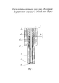
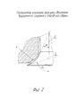
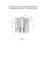
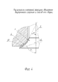
На фиг. 1 представлен эскиз распылителя клапанной форсунки двигателя внутреннего сгорания; на фиг. 2 - вариант клапанного узла, с формой поверхности клапана и седла клапана в виде кривых переменного радиуса, угол между касательными к которым и осью клапанного узла изменяется в диапазоне от 30° до 75°; на фиг. 3 показан способ соединения направляющей клапана и стержня клапана с помощью сварки; на фиг. 4 - эскиз клапанного узла с легкоплавкой вставкой.In FIG. 1 is a sketch of a nozzle of a valve nozzle of an internal combustion engine; in FIG. 2 is a variant of the valve assembly, with the shape of the valve surface and the valve seat in the form of curves of variable radius, the angle between the tangents to which and the axis of the valve assembly varies in the range from 30 ° to 75 °; in FIG. 3 shows a method for connecting a valve guide and a valve stem by welding; in FIG. 4 is a sketch of a valve assembly with a fusible insert.
Распылитель клапанной форсунки (фиг. 1) состоит из цилиндрического корпуса 1 распылителя с каналами подвода топлива 2 внутри него, имеющего сквозное центральное цилиндрическое трехступенчатое отверстие 3, окончание которого выполнено в виде седла 4 клапана, и установленного с возможностью осевого перемещения внутри центрального отверстия 3 стержня 5 клапана, один конец которого выполнен в виде клапана 6 и выставлен наружу корпуса 1 распылителя таким образом, что в совокупности с седлом 4 образует клапанный узел, а другой конец стержня 5 клапана жестко соединен с направляющей 7 клапана, коаксиально установленной в центральном отверстии 3 корпуса 1 распылителя и подпружиненной относительно него с помощью клапанной пружины 8. Зазор h между торцом подпружиненной направляющей 7 клапана и уступом отверстия наибольшего диаметра равен ходу клапана.The atomizer of the valve nozzle (Fig. 1) consists of a
Поверхности клапана 6 и седла 4 выполнены в виде кривых переменного радиуса, величина угла между касательными к которым и осью клапанного узла изменяется в любом диапазоне от 0° до 90° (фиг. 2). Сопряженные поверхности клапанного узла эквидистантны.The surfaces of the
Неподвижность соединения (фиг. 3) направляющей 7 клапана и стержня 5 клапана относительно друг друга обеспечивается одним из методов сварки с помощью сварного шва 9.The immobility of the connection (Fig. 3) of the
Данный распылитель предназначен для использования в форсунках ударного типа, где он работает следующим образом.This sprayer is intended for use in shock-type nozzles, where it works as follows.
При воздействии управляющего импульса от электронного блока управления на электромагнит форсунки, его сердечник через боек (не показано) воздействует на стержень 5 клапана, который перемещается вниз на величину зазора h до упора направляющей 7 клапана в уступ корпуса 1 распылителя. Топливо под давлением поступает от аккумулятора через каналы подвода топлива 2 в центральное трехступенчатое отверстие 3 и через клапанный узел распылителя, образованный клапаном 6 и седлом 4, распыливается в камеру сгорания ДВС.When a control pulse from the electronic control unit exerts an influence on the nozzle electromagnet, its core acts on the
Впрыскивание топлива прекращается при исчезновении управляющего импульса по команде электронного блока управления на электромагнит форсунки, и электромагнитная сила, удерживающая сердечник электромагнита, исчезает, поэтому он возвращается в исходное положение совместно с ударником. Направляющая 7 клапана совместно со стержнем 5 клапана под действием усилия, вызываемого давлением топлива, также возвращаются в исходное положение, и клапанный узел закрывается.Fuel injection stops when the control pulse disappears upon the command of the electronic control unit to the nozzle electromagnet, and the electromagnetic force holding the core of the electromagnet disappears, so it returns to its original position with the hammer. The
Новый способ сборки состоит в следующем (фиг. 1).A new method of assembly is as follows (Fig. 1).
В корпус 1 распылителя вставляют стержень 5 клапана таким образом, чтобы поверхность клапана 6 совпадала с поверхностью седла 4 клапана, затем с противоположной стороны в центральное отверстие 3 на стержень 5 клапана надевают пружину 8, а на седло 4 накладывают кольцевую вставку 10 (фиг. 4) из легкоплавкого материала, номинальный размер которой равен размеру X кольцевой щели клапанного узла в рабочем состоянии, затем направляющую 7 клапана вставляют в центральное отверстие 3 до соприкосновения ее торца с уступом корпуса 1 распылителя и в таком положении запрессовывают стержень 5 клапана в направляющую 7 клапана до соприкосновения его клапанной поверхности с кольцевой вставкой 10 из легкоплавкого материала, после чего клапанный узел нагревают до температуры плавления легкоплавкого материала вставки, расплавляют ее и выдувают воздухом, нагнетаемым через каналы подвода топлива 2.A
Вместо запрессовки стержня 5 клапана в направляющую 7 клапана (как вариант) ее размещают в центральном отверстии 3 и прижимают к уступу корпуса 1 распылителя и в таком положении с противоположной стороны корпуса 1 просовывают стержень 5 клапана в отверстие направляющей 7 клапана до соприкосновения его клапанной поверхности с кольцевой вставкой 10 из легкоплавкого материала, и приваривают направляющую 7 клапана к стержню 5 клапана.Instead of pressing the
Предлагаемое изобретение является актуальным, т.к. его внедрение позволит улучшить распыливание топлива в камере сгорания ДВС, что положительно скажется на процессе его сгорания и будет способствовать увеличению его топливной экономичности и уменьшению вредных выбросов. Клапанные форсунки более технологичны по сравнению с многосопловыми, и управление клапаном, открывающимся по ходу движения топлива, проще, чем клапаном, открывающимся навстречу движению топлива.The present invention is relevant, because its implementation will improve the atomization of fuel in the combustion chamber of the internal combustion engine, which will positively affect the combustion process and will increase its fuel efficiency and reduce harmful emissions. Valve nozzles are more technologically advanced than multi-nozzle ones, and controlling a valve that opens in the direction of travel of the fuel is simpler than a valve that opens toward the movement of fuel.
Для изготовления таких распылителей может быть использовано оборудование такого же класса точности, как и для распылителей, серийно выпускающихся для современной топливоподающей аппаратуры.For the manufacture of such atomizers, equipment of the same accuracy class can be used as for atomizers commercially available for modern fuel supply equipment.
Claims (3)
Priority Applications (1)
| Application Number | Priority Date | Filing Date | Title |
|---|---|---|---|
| RU2017126016A RU2651925C1 (en) | 2017-07-19 | 2017-07-19 | Atomizer of valve injector for internal combustion engine and method of its assembly |
Applications Claiming Priority (1)
| Application Number | Priority Date | Filing Date | Title |
|---|---|---|---|
| RU2017126016A RU2651925C1 (en) | 2017-07-19 | 2017-07-19 | Atomizer of valve injector for internal combustion engine and method of its assembly |
Publications (1)
| Publication Number | Publication Date |
|---|---|
| RU2651925C1 true RU2651925C1 (en) | 2018-04-24 |
Family
ID=62045837
Family Applications (1)
| Application Number | Title | Priority Date | Filing Date |
|---|---|---|---|
| RU2017126016A RU2651925C1 (en) | 2017-07-19 | 2017-07-19 | Atomizer of valve injector for internal combustion engine and method of its assembly |
Country Status (1)
| Country | Link |
|---|---|
| RU (1) | RU2651925C1 (en) |
Citations (6)
| Publication number | Priority date | Publication date | Assignee | Title |
|---|---|---|---|---|
| US4034917A (en) * | 1975-12-22 | 1977-07-12 | Caterpillar Tractor Co. | Variable orifice fuel injection nozzle |
| JPH0261363A (en) * | 1988-06-10 | 1990-03-01 | Orbital Engine Co Pty Ltd | Fuel injection nozzle |
| RU2069788C1 (en) * | 1990-01-26 | 1996-11-27 | Орбитал Энджин Компани (Аустрэлиа) Пти, Лимитед | Fuel nozzle for internal combustion engine |
| WO2005075814A1 (en) * | 2004-01-28 | 2005-08-18 | Siemens Vdo Automotive Spa | Valve body, fluid injector and process for manufacturing a valve body |
| EP1481159B1 (en) * | 2002-02-26 | 2009-10-28 | Robert Bosch Gmbh | Fuel injection valve |
| RU2540347C2 (en) * | 2013-01-24 | 2015-02-10 | Федеральное государственнное бюджетное образовательное учреждение высшего профессионального образования "Ярославский государственный технический университет" | Ice electrically-controlled fuel injector |
-
2017
- 2017-07-19 RU RU2017126016A patent/RU2651925C1/en active
Patent Citations (6)
| Publication number | Priority date | Publication date | Assignee | Title |
|---|---|---|---|---|
| US4034917A (en) * | 1975-12-22 | 1977-07-12 | Caterpillar Tractor Co. | Variable orifice fuel injection nozzle |
| JPH0261363A (en) * | 1988-06-10 | 1990-03-01 | Orbital Engine Co Pty Ltd | Fuel injection nozzle |
| RU2069788C1 (en) * | 1990-01-26 | 1996-11-27 | Орбитал Энджин Компани (Аустрэлиа) Пти, Лимитед | Fuel nozzle for internal combustion engine |
| EP1481159B1 (en) * | 2002-02-26 | 2009-10-28 | Robert Bosch Gmbh | Fuel injection valve |
| WO2005075814A1 (en) * | 2004-01-28 | 2005-08-18 | Siemens Vdo Automotive Spa | Valve body, fluid injector and process for manufacturing a valve body |
| RU2540347C2 (en) * | 2013-01-24 | 2015-02-10 | Федеральное государственнное бюджетное образовательное учреждение высшего профессионального образования "Ярославский государственный технический университет" | Ice electrically-controlled fuel injector |
Similar Documents
| Publication | Publication Date | Title |
|---|---|---|
| JP3527126B2 (en) | Fuel injection device for internal combustion engine | |
| US4192466A (en) | Swirl injection valve | |
| KR930004967B1 (en) | Electronic fuel injector | |
| US7306173B2 (en) | Fuel injection valve | |
| US9739246B2 (en) | Fuel injector with variable spray | |
| CN102132030A (en) | Nozzle body, nozzle assembly and fuel injector, and method for producing a nozzle body | |
| US7237527B2 (en) | Fuel injector for an internal combustion engine | |
| CN103261665A (en) | Fuel injection valve for internal combustion engines | |
| RU2651925C1 (en) | Atomizer of valve injector for internal combustion engine and method of its assembly | |
| JP2007534875A (en) | Valve body, fluid injector, and method of manufacturing valve body | |
| JP2005532504A (en) | Control method for internal combustion engine | |
| US20030192957A1 (en) | Fuel injector tip for control of fuel delivery | |
| EP1467087B1 (en) | Spray pattern element and fuel injection valve with a spray pattern element | |
| JP3924949B2 (en) | Fuel injection nozzle | |
| EP3513056B1 (en) | Fuel injector and piston bowl | |
| US20040256494A1 (en) | Outwardly-opening fuel injector | |
| US7520269B2 (en) | Fuel injector nozzle assembly | |
| RU200998U1 (en) | SPRAYER NOZZLE FOR DIESEL INTERNAL COMBUSTION ENGINE | |
| JPWO2018155091A1 (en) | Fuel injection device | |
| JP3849224B2 (en) | Fuel injection valve | |
| CN102287302A (en) | High-pressure common rail electrical control oil sprayer | |
| JP2000027733A (en) | Fuel injection nozzle | |
| RU2191285C2 (en) | Valve-type nozzle | |
| EA005020B1 (en) | Method for fuel injection in combustion chamber of internal combustion engine | |
| RU2239089C1 (en) | Diesel engine nozzle spray tip |