RU2651571C2 - Reactive synchronous rotor with recess for reducing voltages - Google Patents
Reactive synchronous rotor with recess for reducing voltages Download PDFInfo
- Publication number
- RU2651571C2 RU2651571C2 RU2016134841A RU2016134841A RU2651571C2 RU 2651571 C2 RU2651571 C2 RU 2651571C2 RU 2016134841 A RU2016134841 A RU 2016134841A RU 2016134841 A RU2016134841 A RU 2016134841A RU 2651571 C2 RU2651571 C2 RU 2651571C2
- Authority
- RU
- Russia
- Prior art keywords
- rotor
- jet rotor
- jet
- sheet
- sheets
- Prior art date
Links
Images


Classifications
-
- H—ELECTRICITY
- H02—GENERATION; CONVERSION OR DISTRIBUTION OF ELECTRIC POWER
- H02K—DYNAMO-ELECTRIC MACHINES
- H02K1/00—Details of the magnetic circuit
- H02K1/06—Details of the magnetic circuit characterised by the shape, form or construction
- H02K1/22—Rotating parts of the magnetic circuit
-
- H—ELECTRICITY
- H02—GENERATION; CONVERSION OR DISTRIBUTION OF ELECTRIC POWER
- H02K—DYNAMO-ELECTRIC MACHINES
- H02K1/00—Details of the magnetic circuit
- H02K1/06—Details of the magnetic circuit characterised by the shape, form or construction
- H02K1/22—Rotating parts of the magnetic circuit
- H02K1/24—Rotor cores with salient poles ; Variable reluctance rotors
- H02K1/246—Variable reluctance rotors
-
- H—ELECTRICITY
- H02—GENERATION; CONVERSION OR DISTRIBUTION OF ELECTRIC POWER
- H02K—DYNAMO-ELECTRIC MACHINES
- H02K1/00—Details of the magnetic circuit
- H02K1/06—Details of the magnetic circuit characterised by the shape, form or construction
- H02K1/22—Rotating parts of the magnetic circuit
- H02K1/24—Rotor cores with salient poles ; Variable reluctance rotors
-
- H—ELECTRICITY
- H02—GENERATION; CONVERSION OR DISTRIBUTION OF ELECTRIC POWER
- H02K—DYNAMO-ELECTRIC MACHINES
- H02K1/00—Details of the magnetic circuit
- H02K1/06—Details of the magnetic circuit characterised by the shape, form or construction
- H02K1/22—Rotating parts of the magnetic circuit
- H02K1/28—Means for mounting or fastening rotating magnetic parts on to, or to, the rotor structures
-
- H—ELECTRICITY
- H02—GENERATION; CONVERSION OR DISTRIBUTION OF ELECTRIC POWER
- H02K—DYNAMO-ELECTRIC MACHINES
- H02K15/00—Methods or apparatus specially adapted for manufacturing, assembling, maintaining or repairing of dynamo-electric machines
- H02K15/02—Methods or apparatus specially adapted for manufacturing, assembling, maintaining or repairing of dynamo-electric machines of stator or rotor bodies
- H02K15/024—Methods or apparatus specially adapted for manufacturing, assembling, maintaining or repairing of dynamo-electric machines of stator or rotor bodies with slots
- H02K15/028—Methods or apparatus specially adapted for manufacturing, assembling, maintaining or repairing of dynamo-electric machines of stator or rotor bodies with slots for fastening to casing or support, respectively to shaft or hub
-
- H—ELECTRICITY
- H02—GENERATION; CONVERSION OR DISTRIBUTION OF ELECTRIC POWER
- H02K—DYNAMO-ELECTRIC MACHINES
- H02K29/00—Motors or generators having non-mechanical commutating devices, e.g. discharge tubes or semiconductor devices
- H02K29/06—Motors or generators having non-mechanical commutating devices, e.g. discharge tubes or semiconductor devices with position sensing devices
-
- H—ELECTRICITY
- H02—GENERATION; CONVERSION OR DISTRIBUTION OF ELECTRIC POWER
- H02K—DYNAMO-ELECTRIC MACHINES
- H02K2201/00—Specific aspects not provided for in the other groups of this subclass relating to the magnetic circuits
- H02K2201/06—Magnetic cores, or permanent magnets characterised by their skew
Abstract
Description
Данное изобретение относится к листу реактивного синхронного ротора, который выполнен по существу в виде круглого диска. Он имеет центральную выемку на центре и вдоль оси d (направление легкого намагничивания) участок проведения потока, распространяющийся в радиальном направлении от центральной выемки до находящегося на наружном краю листа реактивного синхронного ротора соединительного кольца. Кроме того, изобретение относится к реактивному синхронному ротору, включающему в себя пакет сердечника из множества листов реактивного синхронного ротора, а также к способу его изготовления.This invention relates to a sheet of a synchronous reactive rotor, which is made essentially in the form of a circular disk. It has a central recess in the center and along the d axis (direction of easy magnetization) a section of the flow, extending in the radial direction from the Central recess to located on the outer edge of the sheet of the synchronous synchronous rotor of the connecting ring. In addition, the invention relates to a reactive synchronous rotor, including a core package of multiple sheets of a reactive synchronous rotor, as well as to a method for its manufacture.
Подобные листы реактивного синхронного ротора с соответствующими выемками известны из патентного описания US 5818140 A. Из листов реактивного синхронного ротора можно собирать пакет сердечника и соответствующий ротор. Благодаря вырезам возникают изогнутые полосовидные участки листа, которые служат в качестве участков проведения потока и проводят магнитный поток необходимым для предоставления необходимого магнитного сопротивления ротора образом. Между отдельными участками проведения потока благодаря вырезам находится воздух, то есть немагнитная область, которая действует в качестве барьера магнитного потока. Благодаря полосовидным участкам проведения потока возникает высокий выход крутящего момента. Магнитная проницаемость пакета сердечника в направлении оси q, то есть направлении блокировки магнитного потока сравнительно мала ввиду немагнитных областей. Полосовидные участки проведения потока проходят поперек оси q и соединяют соседние в окружном направлении полюса ротора, которые в каждом случае расположены на осях d (направлениях легкого намагничивания). Однако вырезы для предоставления немагнитных областей или для образования участков проведения потока приводят к ослаблению механической устойчивости пакета сердечника, так что описанный ротор не подходит для больших частот вращения, в частности для частот вращения больше 3000 оборотов в минуту. По этой причине реактивные синхронные электродвигатели описанного типа не подходят для требований к частотам вращения в области, например, автомобилей с электрическими приводами.Such reactive synchronous rotor sheets with corresponding recesses are known from US Pat. No. 5,818,140 A. From the reactive synchronous rotor sheets, a core pack and a corresponding rotor can be assembled. Thanks to the cutouts, curved strip-like sections of the sheet appear, which serve as sections of the flow and conduct magnetic flux in a manner necessary to provide the necessary magnetic resistance of the rotor. Between the individual sections of the flow, thanks to the cutouts, there is air, that is, a non-magnetic region that acts as a barrier to the magnetic flux. Due to the strip-like sections of the flow, a high torque output occurs. The magnetic permeability of the core packet in the q axis direction, that is, the magnetic flux blocking direction, is relatively small due to non-magnetic regions. The streaky sections of the flow pass across the q axis and connect the rotor poles adjacent in the circumferential direction, which in each case are located on the d axes (directions of easy magnetization). However, cutouts for providing non-magnetic regions or for forming flow conduction sites weaken the mechanical stability of the core stack, so the described rotor is not suitable for high rotational speeds, in particular for rotational speeds greater than 3000 rpm. For this reason, jet synchronous motors of the type described are not suitable for the requirements for the rotational speeds in the field, for example, cars with electric drives.
Таким образом, в частности лист ротора реактивного синхронного электродвигателя (коротко: лист реактивного синхронного ротора) выполнен на основе принципа действия в отношении оси d и q более высокой различной радиальной устойчивости. Так, ось d образована участком проведения потока, выходящим из листа от внутреннего к внешнему диаметру, в то время как ось q прервана барьерами потока.Thus, in particular, the rotor sheet of the jet synchronous electric motor (in short: the sheet of the jet synchronous rotor) is made on the basis of the principle of action with respect to the d and q axes of a higher different radial stability. Thus, the d axis is formed by a flow conducting section extending from the sheet from the inner to the outer diameter, while the q axis is interrupted by the flow barriers.
Листы ротора соединяются, например, посредством цилиндрической посадки с натягом на вал. При высоких частотах вращения натяг посадки должен выполняться более высоким, так как благодаря центробежной силе доходит до расширения листа ротора на внутреннем диаметре, и передача крутящего момента на вал уменьшается. Призматические шпонки для передачи крутящего момента были бы также нежелательны, так как выбираемый на листах паз дополнительно уменьшил бы устойчивость.The rotor sheets are connected, for example, by means of a cylindrical fit with an interference fit on the shaft. At high rotational speeds, the interference fit should be higher, since due to centrifugal force it reaches the expansion of the rotor sheet on the inner diameter, and the transmission of torque to the shaft is reduced. Torque dowels would also be undesirable, since the groove selected on the sheets would further reduce stability.
Благодаря различной устойчивости на осях при напрессовке доходит до различных деформаций и тем самым до недопустимых напряжений на внешних перемычках или на внешнем соединительном кольце листа ротора, в частности на перемычке непосредственно рядом с осью d. Сплошной материал на оси d смещается в виде деформации от внутреннего к наружному диаметру, в то время как в соседней области ввиду барьеров потока обходится без деформации изнутри наружу.Due to the different stability on the axes during pressing, it reaches various deformations and thereby to unacceptable stresses on the external jumpers or on the external connecting ring of the rotor sheet, in particular on the jumper directly next to the d axis. The continuous material on the d axis shifts in the form of deformation from the inner to the outer diameter, while in the neighboring region, due to flow barriers, without deformation from the inside out.
Дополнительно перемычки, которые удерживают вместе участки проведения потока, при вращении сильно нагружаются центробежной силой. При относительно высоком растягивающем напряжении, которое может вызываться уже посадкой с натягом, для нагрузки центробежной силой остается лишь незначительный резерв, или он не остается вовсе. Таким образом, подобный реактивный синхронный ротор подходит лишь для относительно низких частот вращения.Additionally, the jumpers that hold together the sections of the flow, during rotation, are heavily loaded by centrifugal force. At a relatively high tensile stress, which can already be caused by an interference fit, only a small reserve remains for the load by centrifugal force, or it does not remain at all. Thus, such a synchronous reactive rotor is only suitable for relatively low rotational speeds.
Возможная оптимизация заключается в том, чтобы встраивать между валом и листом ротора элементы геометрического замыкания, для того чтобы была возможность отводить усилия посадки с натягом и одновременно передавать высокий крутящий момент. В качестве элементов геометрического замыкания могут использоваться шпоночные канавки и призматические шпонки, притупления или же валы с многоугольными поперечными сечениями. И хотя благодаря этим мерам ввиду нетребующейся посадки с натягом можно предотвращать растягивающие напряжения, тем не менее, как было указано выше, лист благодаря шпоночным пазам при определенных обстоятельствах дополнительно теряет устойчивость, и изготовление или соединение с валами затруднено.A possible optimization is to integrate geometric locking elements between the shaft and the rotor sheet in order to be able to deflect interference fit while transmitting high torque. As keying elements, keyways and keyways, blunts or shafts with polygonal cross-sections can be used. And although thanks to these measures, due to the unnecessary fit with an interference fit, tensile stresses can be prevented, nevertheless, as mentioned above, the sheet due to keyways under certain circumstances additionally loses stability, and manufacturing or connecting with shafts is difficult.
Таким образом, задача данного изобретения заключается в предоставлении листа реактивного синхронного ротора, при помощи которого может собираться просто изготавливаемый ротор, который не подвержен чрезмерным растягивающим напряжениям.Thus, the object of the present invention is to provide a sheet of a synchronous reactive rotor by means of which a simply manufactured rotor can be assembled which is not subject to excessive tensile stresses.
Согласно изобретению эта задача решается с помощью листа реактивного синхронного ротора,According to the invention, this problem is solved using a sheet of a synchronous reactive rotor,
- который выполнен по существу в виде круглого диска и имеет одну или несколько осей d, причем каждая ось d, будучи разделена центром листа реактивного синхронного ротора, имеет две половины оси d и включает в себя- which is made essentially in the form of a circular disk and has one or more axes d, and each axis d, being divided by the center of the sheet of the synchronous reactive rotor, has two halves of the axis d and includes
- центральную выемку на центре листа реактивного синхронного ротора и- a Central recess in the center of the sheet of the synchronous rotor and
- вдоль каждой половины оси d в каждом случае один участок проведения потока, распространяющийся в радиальном направлении от центральной выемки до находящегося на наружном краю листа реактивного синхронного ротора соединительного кольца, причем- along each half of the axis d in each case, one section of the flow, extending in the radial direction from the Central recess to located on the outer edge of the sheet of the synchronous reactive rotor of the connecting ring, and
- на каждом участке проведения потока на соответствующей половине оси d расположена выемка для уменьшения напряжения, так что с обеих сторон от соответствующей половины оси d на соответствующем участке проведения потока в каждом случае образован участок проведения частичного потока, и- a recess is located in each section of the flow conduit on the corresponding half of the d axis so that a partial flow conduction section is formed in each case on both sides of the corresponding half of the d axis in each respective flow conduit, and
- сумма в каждом случае наименьшего поперечного сечения обоих участков проведения частичного потока по существу больше или равна наименьшей, перпендикулярной к соответствующей половине оси d площади поперечного сечения участка проведения потока в радиальном направлении выше выемки.- the sum in each case of the smallest cross-section of both sections of the partial flow conducting is substantially greater than or equal to the smallest perpendicular to the corresponding half axis d of the cross-sectional area of the flow conducting section in the radial direction above the recess.
Предпочтительным образом благодаря выемке на каждом участке проведения потока нескольких половин осей d уменьшается жесткость листа реактивного синхронного ротора в направлении оси d. При этом выемка расположена и/или выполнена таким образом, что соответствующий участок проведения потока не суживается больше, чем сужение, которое участок проведения потока имеет на своем самом узком месте без выемки. Это означает, что магнитный поток не ухудшается больше, чем на самом узком сплошном месте участка проведения потока, которое, как правило, расположено в радиальном направлении максимально наружу на соединительном кольце. Тем самым найден идеальный компромисс между уменьшением жесткости и ухудшением магнитного потока. По сравнению с уровнем техники у изобретения листы реактивного синхронного ротора не должны быть соединены друг с другом для образования пакета сердечника. Предпочтительно они соединены исключительно непосредственно в области центральной выемки с валом ротора. Например, соединительные пальцы, соединения с силовым замыканием расположенных друг около друга листов реактивного синхронного ротора или тому подобное могут экономиться. У изобретения передача усилия между листом реактивного синхронного ротора и валом осуществляется предпочтительно напрямую или непосредственно, а именно без содействия дальнейших компонентов. Со стороны реактивного синхронного ротора задача решается с помощью пакета сердечника, который имеет листы реактивного синхронного ротора согласно изобретению.Advantageously, due to the recess in each flow section, several halves of the d axes decrease the stiffness of the sheet of the synchronous rotor in the d axis direction. In this case, the recess is located and / or made in such a way that the corresponding section of the flow does not taper more than the narrowing, which the section of the flow has at its narrowest point without a recess. This means that the magnetic flux does not deteriorate more than at the narrowest continuous site of the flux, which is usually located in the radial direction as far outward as possible on the connecting ring. Thus, an ideal compromise was found between a decrease in stiffness and a decrease in magnetic flux. Compared with the prior art, the sheets of the synchronous rotor do not have to be connected to each other to form a core package. Preferably, they are connected exclusively directly in the region of the central recess to the rotor shaft. For example, connecting fingers, power-locked connections of adjacent synchronous rotor sheets or the like can be saved. In the invention, the transfer of force between the sheet of the synchronous reactive rotor and the shaft is preferably carried out directly or directly, namely without the assistance of further components. From the side of the reactive synchronous rotor, the problem is solved with the help of a core package, which has the sheets of the reactive synchronous rotor according to the invention.
Выемка для уменьшения напряжения может быть полностью окружена материалом листа реактивного синхронного ротора. Это означает, что выемка полностью расположена внутри соответствующего участка проведения потока. Это имеет то преимущество, что центральная выемка на всем своем периметре может быть расположена с фрикционным замыканием на чисто цилиндрическом валу. В частности, край центральной выемки листа реактивного синхронного ротора, предпочтительно в области q между выемками для уменьшения напряжения, может иметь ответную форму относительно формы вала. Вследствие этого может достигаться передача большого усилия при значительном предотвращении перегрузки листа реактивного синхронного ротора. Уменьшение напряжения относится к уменьшению механических напряжений.The recess for reducing voltage can be completely surrounded by the sheet material of the synchronous rotor. This means that the recess is completely located inside the corresponding section of the flow. This has the advantage that the central recess along its entire perimeter can be located with a frictional closure on a purely cylindrical shaft. In particular, the edge of the central recess of the sheet of the synchronous rotor, preferably in the region q between the recesses to reduce stress, may have a reciprocal shape with respect to the shape of the shaft. As a result of this, a large force transmission can be achieved while significantly preventing overloading of the sheet of the synchronous rotor. Stress reduction refers to the reduction of mechanical stress.
В альтернативном варианте осуществления пустое пространство выемки соединено с пустым пространством центральной выемки. Это означает, что оба пустых пространства переходят непосредственно друг в друга или границы пустых пространств пересекаются друг с другом или переходят друг в друга.In an alternative embodiment, the empty space of the recess is connected to the empty space of the central recess. This means that both empty spaces pass directly into each other or the boundaries of empty spaces intersect with each other or pass into each other.
В частности, две из осей d могут быть расположены перпендикулярно друг к другу, и две оси q могут быть расположены, образуя биссектрисы между осями d, причем изогнутые полосовидные участки листа расположены перпендикулярно к осям q и участки листа отделены друг от друга вырезами. Тем самым можно реализовывать четырехполюсный реактивный синхронный ротор, чьи полюса расположены в каждом случае со смещением на 90°. Посередине между в каждом случае двумя соседними полюсами находятся оси q c направлением магнитного барьера. Таким образом, соседние оси d и q смещены друг относительно друга на 45°.In particular, two of the d axes can be arranged perpendicular to each other, and the two q axes can be arranged to form bisectors between the d axes, with curved strip-like sections of the sheet located perpendicular to the q axes and sections of the sheet separated by cutouts. Thus, it is possible to realize a four-pole synchronous reactive rotor, whose poles are located in each case with a shift of 90 °. In the middle between, in each case, two adjacent poles are the q axis with the direction of the magnetic barrier. Thus, the adjacent axes d and q are offset relative to each other by 45 °.
Далее в дополнение к выемке или выемкам для уменьшения напряжения лист реактивного синхронного ротора может иметь, по меньшей мере, одну опознавательную выемку. Таким образом, наряду с центральной выемкой, выемками для уменьшения напряжения и вырезами для сокращения потока дополнительно предусмотрена, по меньшей мере, одна выемка в качестве опознавательной метки, для того чтобы проще регистрировать ориентацию листа реактивного синхронного ротора. Это полезно при составлении пакета сердечника. Подобные опознавательные выемки, как правило, существенно меньше, чем все остальные вырезы, так как они не должны оказывать влияния ни на магнитный поток, ни на механическую устойчивость.Further, in addition to the recess or recesses, in order to reduce the voltage, the sheet of the reactive synchronous rotor may have at least one identification recess. Thus, along with the central recess, recesses to reduce stress and cutouts to reduce the flow, at least one recess is additionally provided as an identification mark in order to more easily register the orientation of the sheet of the synchronous rotor. This is useful when compiling a core package. Such identification notches, as a rule, are substantially smaller than all other notches, since they should not affect either magnetic flux or mechanical stability.
Согласно варианту осуществления предлагается то, что центральная выемка выполнена исключительно для соединения листа реактивного синхронного ротора с валом реактивного синхронного ротора. Вследствие этого лист реактивного синхронного ротора может закрепляться на валу ротора исключительно в области центральной выемки. Вследствие этого могут экономиться дальнейшие варианты закрепления. Лист реактивного синхронного ротора соединен с вылом ротора предпочтительно исключительно в области центральной выемки. Соединение с соседними листами реактивного синхронного ротора может также экономиться. Центральная выемка предпочтительно выполнена таким образом, что она может соединяться с валом посредством посадки, в частности посадки с натягом. Вследствие этого может достигаться надежное соединение.According to an embodiment, it is proposed that the central recess is made solely for connecting the sheet of the reactive synchronous rotor to the shaft of the reactive synchronous rotor. As a result of this, the sheet of the synchronous reactive rotor can be fixed on the rotor shaft exclusively in the region of the central recess. As a result, further fixing options can be saved. A synchronous rotor rotor sheet is connected to the rotor opening, preferably exclusively in the region of the central recess. Connecting to adjacent sheets of a jet synchronous rotor can also be economized. The central recess is preferably made in such a way that it can be connected to the shaft by means of a fit, in particular an interference fit. As a result, a reliable connection can be achieved.
Согласно дальнейшему варианту осуществления предлагается то, что лист реактивного синхронного ротора имеет направляющий скошенный элемент, который предпочтительно расположен на внешнем периметре листа реактивного синхронного ротора. Сверх этого, направляющий скошенный элемент может быть также расположен в области центральной выемки листа реактивного синхронного ротора. Направляющий скошенный элемент может быть образован, например, выступом, углублением, комбинациями из них и/или тому подобным. Направляющий скошенный элемент предпочтительно выполнен таким образом, что он по существу не образует дисбаланс при надлежащей целевой эксплуатации. Например, выполненные по существу идентично, задающие перекос элементы могут быть расположены в радиальном направлении на противоположных сторонах на листе реактивного синхронного ротора. Кроме того, задающие перекос элементы предпочтительно выполнены для взаимодействия с задающей перекос кулисой, так что является возможным располагать листы реактивного синхронного ротора предварительно задаваемым образом с угловым смещением друг относительно друга в пакете сердечника. Сверх этого, может быть предусмотрено то, что направляющий скошенный элемент после окончательного изготовления реактивного синхронного ротора удаляется. Это является предпочтительным, в частности, при выступающих в радиальном направлении, задающих перекос элементах.According to a further embodiment, it is proposed that the reactive synchronous rotor sheet has a beveled guiding element, which is preferably located on the outer perimeter of the reactive synchronous rotor sheet. On top of this, the tapered guide element can also be located in the region of the central recess of the sheet of the synchronous rotor. The guide beveled element may be formed, for example, by a protrusion, recess, combinations of them and / or the like. The chamfered guide element is preferably designed in such a way that it does not substantially create an imbalance when properly targeted. For example, skewed substantially identically skew defining elements may be located in the radial direction on opposite sides of the synchronous rotor sheet. In addition, the skew-setting elements are preferably made to interact with the skew-setting backstage, so that it is possible to arrange the sheets of the synchronous rotor in a predetermined manner with angular displacement relative to each other in the core package. On top of this, it can be provided that the guide beveled element after the final manufacture of the reactive synchronous rotor is removed. This is preferable, in particular, when protruding in the radial direction, defining skew elements.
Из множества подобных листов реактивного синхронного ротора может образовываться пакет сердечника, который может монтироваться на вал. При этом предпочтительно, если вал с передачей вращательного движения соединен с пакетом сердечника лишь посредством фрикционного соединения. Это означает, что центральная выемка, за исключением дальнейших выемок, которые вдаются в нее, может иметь форму круга, и равным образом вал может образовываться чисто с формой круглого цилиндра. Вследствие этого можно реализовывать очень простую конструкцию вала.From a plurality of such sheets of a synchronous rotor, a core package can be formed which can be mounted on a shaft. Moreover, it is preferable if the shaft with the transmission of rotational motion is connected to the core package only by means of a friction connection. This means that the central recess, with the exception of further recesses that protrude into it, can be in the shape of a circle, and likewise, the shaft can be formed purely with the shape of a round cylinder. As a result, a very simple shaft design can be realized.
Кроме того, пакет сердечника может иметь перекос. При этом отдельные листы пакета сердечника смещены в окружном направлении друг относительно друга на незначительное угловое значение, вследствие чего пульсация крутящего момента электрической машины и, в частности, реактивного синхронного электродвигателя может уменьшаться.In addition, the core package may be skewed. In this case, the individual sheets of the core package are displaced in the circumferential direction relative to each other by a small angular value, as a result of which the ripple of the torque of the electric machine and, in particular, of the synchronous reactive electric motor can be reduced.
Предпочтительно выемки на каждой отдельной оси d или на всех осях d имеют одинаковые размеры. Равным образом выемки на каждой отдельной оси d или на всех осях d должны иметь одинаковое расстояние до центра листа реактивного синхронного ротора. Вследствие этого напряжения могут уменьшаться во всех областях листа реактивного синхронного ротора.Preferably, the recesses on each individual d axis or on all d axes have the same dimensions. Likewise, the recesses on each individual d axis or on all d axes should have the same distance to the center of the sheet of the synchronous reactive rotor. As a result of this, stresses can decrease in all areas of the sheet of the synchronous rotor.
Со стороны способа в качестве решения задачи предлагается то, что в способе изготовления реактивного синхронного ротора, имеющего пакет сердечника из множества листов реактивного синхронного ротора и вал, используются листы реактивного синхронного ротора согласно изобретению, причем способ включает в себя следующие шаги:On the part of the method, it is proposed as a solution to the problem that in the method of manufacturing a reactive synchronous rotor having a core package of a plurality of sheets of a reactive synchronous rotor and a shaft, sheets of a reactive synchronous rotor according to the invention are used, the method comprising the following steps:
- укладывание в стопу необходимого для целевой функции пакета сердечника количества листов реактивного синхронного ротора для образования стопы, причем листы реактивного синхронного ротора располагаются соосно друг к другу,- stacking the number of sheets of the reactive synchronous rotor necessary for the core function of the core package to form the stack, the sheets of the reactive synchronous rotor being aligned with each other,
- расположение в каждом случае одной концевой пластины на противоположных концах стопы,- the location in each case of one end plate at opposite ends of the foot,
- нагрев стопы до заданной температуры и- heating the foot to a predetermined temperature and
- введение имеющего более низкую температуру, чем листы реактивного синхронного ротора вала, в образованное центральными выемками листов реактивного синхронного ротора отверстие, причем диаметр вала выбирается таким образом, что при выравнивании температур между стопой и валом образуется посадка с натягом.- the introduction of a lower temperature than the sheets of the reactive synchronous rotor of the shaft into the hole formed by the central recesses of the sheets of the reactive synchronous rotor, the diameter of the shaft being selected in such a way that an interference fit is formed when the temperatures are equalized between the stack and the shaft.
Изобретение благодаря использованию листов реактивного синхронного ротора согласно изобретению позволяет отказаться от дальнейших вариантов закрепления. Вследствие этого может достигаться не только наиболее простой способ изготовления, но и исключаются также дополнительные крепежные средства, которые наряду с издержками требовали бы также особых мер с точки зрения целевой эксплуатации. Предпочтительно стопа может подготавливаться в форме и нагреваться до заданной температуры, причем затем ненагретый вал может вводиться в образованное центральными выемками отверстие. Например, разница температур может составлять от 100° до 250°C, предпочтительно от 150 до 220°C, наиболее предпочтительно 180°C. Диаметры отверстия и вала согласованы друг с другом таким образом, что при уравнивании или выравнивании температур между листами реактивного синхронного ротора и валом образуется посадка с натягом.The invention due to the use of sheets of a jet synchronous rotor according to the invention allows to abandon further fixing options. As a result of this, not only the simplest manufacturing method can be achieved, but also additional fasteners which, along with costs, would also require special measures in terms of targeted operation, can be eliminated. Preferably, the foot may be prepared in shape and heated to a predetermined temperature, whereupon the unheated shaft may then be introduced into the hole formed by the central recesses. For example, the temperature difference may be from 100 ° to 250 ° C, preferably from 150 to 220 ° C, most preferably 180 ° C. The diameters of the holes and the shaft are coordinated with each other in such a way that when equalizing or equalizing the temperatures between the sheets of the reactive synchronous rotor and the shaft, an interference fit is formed.
Кроме того, предлагается то, что на концах стопы в каждом случае располагается втулка с отверстием втулки, причем отверстие втулки имеет тот же диаметр, как и центральные выемки листов реактивного синхронного ротора. Благодаря предусмотрению втулок может достигаться то, что во время изготовления пакета сердечника может в значительной степени предотвращаться развертка листов реактивного синхронного ротора, в частности во время введения вала в отверстие. С этой целью может быть предусмотрено то, что втулки на своем соответствующем положении зафиксированы. Сверх этого, при помощи втулок может достигаться то, что во время целевой эксплуатации может обеспечиваться придание устойчивость пакету сердечника в целом. Предпочтительно концы стопы подпираются втулками.In addition, it is proposed that at the ends of the foot in each case there is a sleeve with a hole in the sleeve, the hole of the sleeve having the same diameter as the central recesses of the sheets of the jet synchronous rotor. Due to the provision of the bushings, it can be achieved that during the production of the core package, the sweep of the sheets of the synchronous rotor can be largely prevented, in particular during the introduction of the shaft into the hole. For this purpose, it may be provided that the bushings are locked in their respective position. On top of this, with the help of the bushings, it can be achieved that during the target operation, stability can be ensured for the core package as a whole. Preferably, the ends of the foot are supported by bushings.
Далее предлагается то, что стопа образуется в форме для протяжки с задающей перекос кулисой. Форма для протяжки служит, в частности, для того, чтобы при формировании стопы листы реактивного синхронного ротора располагать и удерживать в необходимой ориентации рядом друг с другом. При этом посредством задающей перекос кулисы может обеспечиваться ориентация листов реактивного синхронного ротора друг относительно друга. Таким образом, форма для протяжки позволят простым и надежным образом реализовывать перекос пакета сердечника.Further, it is proposed that the foot is formed in a form for broaching with deflecting backstage. The form for broaching serves, in particular, in order to position and hold the sheets of the synchronous rotor in the formation of the foot and hold them in the necessary orientation next to each other. In this case, by means of the deflecting backstage, the sheets of the synchronous reactive rotor can be oriented with respect to each other. Thus, the form for broaching will allow a simple and reliable way to realize the skew of the core package.
Далее предлагается то, что стопа на своих концах стопы нагружается давлением. Вследствие этого может достигаться то, что листы реактивного синхронного ротора могут за короткое время нагреваться до соразмерной температуры. Одновременно может достигаться то, что листы реактивного синхронного ротора расположены в каждом случае непосредственно рядом друг с другом и могут в значительной степени предотвращаться нежелательные воздушные зазоры.It is further suggested that the foot at its ends is loaded with pressure. As a consequence of this, it can be achieved that the sheets of the synchronous reactive rotor can be heated to a commensurate temperature in a short time. At the same time, it can be achieved that the sheets of the jet synchronous rotor are located in each case directly adjacent to each other and unwanted air gaps can be largely prevented.
Наиболее предпочтительно, если вал вводится в нагруженном давлением состоянии стопы. Вследствие этого может достигаться то, что листы стопы реактивного синхронного ротора сохраняют свое положение даже при механическом воздействии во время введения вала.Most preferably, the shaft is inserted in a pressure-loaded state of the foot. As a consequence of this, it can be achieved that the sheets of the foot of the synchronous rotor rotor retain their position even under mechanical stress during the introduction of the shaft.
Сверх этого, предлагается то, что во время выравнивания температур давление воздействует на стопу. Вследствие этого может достигаться то, что стопа изменяет свою температуру наиболее равномерно. Вследствие этого образуется надежная посадка с натягом относительно введенного вала. Вследствие этого коробление, неоднородности или тому подобное могут в значительной степени предотвращаться.On top of this, it is suggested that during temperature equalization, pressure acts on the foot. As a result of this, it can be achieved that the foot changes its temperature most evenly. As a result of this, a secure fit is formed with an interference fit with respect to the inserted shaft. As a result, warpage, discontinuities or the like can be largely prevented.
Далее данное изобретение разъясняется более подробно при помощи приложенных чертежей, на которых показаны:Further, the invention is explained in more detail using the attached drawings, which show:
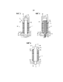
фиг. 1 - лист реактивного синхронного ротора согласно данному изобретению на схематичном виде сверху;FIG. 1 is a sheet of a jet synchronous rotor according to this invention in a schematic top view;
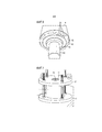
фиг. 2 - пакет сердечника ротора с множеством листов реактивного синхронного ротора согласно фиг. 1 на схематичном виде в перспективе;FIG. 2 shows a rotor core package with multiple sheets of a jet synchronous rotor according to FIG. 1 in a schematic perspective view;
фиг. 3 - на схематичном виде в разрезе стопа необходимого для целевой функции пакета сердечника ротора количества листов реактивного синхронного ротора для образования стопы;FIG. 3 is a schematic sectional view of a stop of the number of sheets of a reactive synchronous rotor necessary for the target function of the rotor core package to form a foot;
фиг. 4 - на схематичном виде в разрезе расположение в каждом случае одной концевой пластины и нагрев стопы;FIG. 4 - in a schematic view in section, the location in each case of one end plate and the heating of the foot;
фиг. 5 - на схематичном виде в разрезе введение вала ротора и образование посадки с натягом;FIG. 5 is a schematic sectional view of the introduction of the rotor shaft and the formation of an interference fit;
фиг. 6 - на схематичном виде в перспективе реактивный синхронный ротор согласно изобретению; иFIG. 6 is a schematic perspective view of a jet synchronous rotor according to the invention; and
фиг. 7 - на схематичном виде в перспективе альтернативный вариант осуществления для расположения в каждом случае одной концевой пластины и нагрева стопы на основе пакета сердечника ротора согласно фиг. 2.FIG. 7 is a schematic perspective view of an alternative embodiment for arranging in each case one end plate and heating the stack based on the rotor core package of FIG. 2.
Описанные в дальнейшем более подробно примеры осуществления представляют собой предпочтительные варианты осуществления данного изобретения.Described in more detail below, exemplary embodiments are preferred embodiments of the present invention.
Изображенный на фиг. 1 лист 18 реактивного синхронного ротора имеет выемки 22, которые образуют магнитные барьеры. Выемки 22, так же как и все остальные выемки, обычно образуются посредством пробивки. Они образуют немагнитные области и таким образом действуют в качестве барьеров магнитного потока. Таким образом, между выемками 22 образуются секции проведения потока, по которым магнитный поток проводится при соответствующем режиму эксплуатации намагничивании.Depicted in FIG. 1, the
Изображенный на фиг. 1 лист 18 реактивного синхронного ротора используется для четырехполюсного реактивного синхронного ротора. В соответствии с этим лист 18 реактивного синхронного ротора имеет две расположенные перпендикулярно друг к другу оси d, которые представляют собой направления легкого намагничивания и которые, будучи разделены центром листа 18 реактивного синхронного ротора, имеют соответствующие половины 32 осей d. Направления легкого намагничивания образованы секциями 24 проведения потока, которые по большей части проходят непрерывно по соответствующим половинам 32 осей d, если не принимается во внимание центральная выемка 2, которая служит для приема вала.Depicted in FIG. 1
Выемки 22, которые служат в качестве магнитного барьера, проходят по существу в виде дуги от одного полюса к соседнему полюсу. Сверх этого, они выполнены по существу в виде полос. По причинам устойчивости они могут быть прерваны перемычками 26. Таким образом, между дугообразными полосовидными выемками 22 образуются также полосовидные дугообразные участки 24 проведения потока.The
Дугообразные немагнитные выемки 22 между соседними полюсами проходят перпендикулярно к осям q 30, которые расположены, образуя биссектрисы между осями d. Таким образом, на осях q 30 происходит блокировка магнитного поля. Для более подробного принципа действия следует обратиться к ссылке на упомянутый вначале патент US 5818140 A от Vagati.Arcuate
На фиг. 2 показан реактивный синхронный ротор или кратко ротор 10 без вала. Ротор 10 может быть установлен в реактивный синхронный электродвигатель. Например, реактивный синхронный электродвигатель может быть приводным двигателем для электроприводного автомобиля. В смонтированном состоянии в проходное отверстие 12 ротора 10, которое образуется посредством центральных выемок 2, вставлен не изображенный на фиг. 2 вал реактивного синхронного электродвигателя. Предпочтительно ротор 10 напрессован на вал. В этом случае вал и тем самым ротор 10 установлены с возможностью вращения вокруг оси A вращения, так что ротор 10 в (неизображенном) статоре реактивного синхронного электродвигателя может осуществлять вращение R вокруг оси A вращения. Диаметр ротора 10 в радиальном направлении может составлять, например, 20 см и более. Длина ротора 10 в осевом направлении может составлять, например, 30 см и более.In FIG. 2 shows a synchronous reactive rotor or, briefly,
В качестве магнитно-активного элемента ротор 10 имеет пакет 14 сердечника, который образован из нескольких слоев 16, которые в каждом случае имеют мягкомагнитный, в частности ферромагнитный, материал. Этот материал получается из отдельных листов согласно фиг. 1. Кроме того, слои имеют изолирующие электричество частичные слои, для того чтобы блокировать вихревые токи в пакете 14 сердечника. Ради видимости из слоев 16 на фиг. 2 снабжены ссылочными позициями лишь некоторые.As a magnetically active element, the
Таким образом, каждый слой 16 образуется по существу посредством одного листа 18 ротора. На фиг. 2 ссылочной позицией снабжен лишь лист 18 ротора, который находится на торцевой стороне 20 в осевом направлении вдоль оси A на переднем конце.Thus, each
Листы 18 ротора расположены на одной прямой в пакете 14 сердечника в осевом направлении друг за другом таким образом, что выемки 22 и соответственно также участки 24 проведения потока совпадают в осевом направлении, если не предусмотрен перекос. Все листы ротора слоев 16 могут иметь одинаковую форму.The
Чтобы ротор 10 на наружной поверхности был замкнут, каждый лист 18 ротора имеет на своем наружном краю замкнутое соединительное кольцо 28. Оно фиксирует также участки 24 проведения потока.In order for the
Пример на фиг. 1 и 2 относится к четырехполюсному ротору. Однако количество полюсов может быть также выбрано большим. В наиболее оптимальном случае проходное отверстие 12 ротора 10 имеет форму круглого цилиндра и соответствующий вал также имеет форму круглого цилиндра. В этом случае ротор 10 или пакет 14 сердечника соединяется с валом посредством посадки с натягом. Таким образом, крутящий момент передается с ротора на вал исключительно посредством фрикционного соединения. Посадка с натягом должна рассчитываться в соответствии с необходимым крутящим моментом и может передавать очень высокие усилия. Благодаря структуре листов 18 реактивного синхронного ротора усилие вдоль осей d 32 проводится в известных сечениях листов практически без ослабления от центральной выемки 2 наружу к соединительному кольцу 28, так как участки проведения потока именно в этих известных сечениях листов непрерывно проходят от центральной выемки 2 до соединительного кольца 28. В областях соединительного кольца между полюсами или осями d 32 усилие посадки с натягом лишь уменьшается или и вовсе не передается, так как выемки 22 блокируют это. Поэтому в областях 4 соединительного кольца 28 возникают очень высокие растягивающие напряжения, которые могут приводить к разрушению листов 18 ротора и тем самым самого ротора 10.The example of FIG. 1 and 2 refers to a four-pole rotor. However, the number of poles can also be selected large. In the most optimal case, the
Для того чтобы сокращать деформацию или растягивающие напряжения в областях 4 соединительного кольца 28 на каждой половине оси d, согласно изобретению выполняются выемки 6 в области осей d или половин 32 осей d. Такая выемка 6, которая может также выполняться посредством пробивки, прерывает линию непосредственного действия усилия вдоль соответствующей половины 32 оси d. Выемка 6 может деформироваться, так что возникают меньшие деформации соединительного кольца 28 в области соответствующей половины 32 оси d и тем самым также меньшие растягивающие напряжения в областях 4 соединительных колец 28. Таким образом, опасность разрушения или повреждения в этих областях значительно снижена.In order to reduce deformation or tensile stresses in the
Выемка 6 должна иметь такие размеры, что она практически не обладает воздействиями на магнитный поток. Это может достигаться вследствие того, что магнитный поток на секции 24 проведения потока в области оси d ограничивается не сильнее, чем в своем самом узком месте в направлении потока. То есть поток не должен получать более узкие проходные сечения, чем у сечения листа без выемок 6.The
Самое узкое место 34 для магнитного потока в области полюсов расположено на переходе секции 24 проведения потока, которая проходит вдоль соответствующей половины 32 оси d, в соединительное кольцо 28. В этом месте лист суживается благодаря прилегающим выемкам 22, которые здесь приближаются друг к другу на минимальное расстояние. Таким образом, на внутреннем краю соединительного кольца 28 возникает узкое место с шириной a. Согласно изобретению магнитный поток на секции 24 проведения потока должен быть ограничен не более чем в узком месте 34.The
Благодаря выемке 6 на участке 24 проведения потока этот участок делится на две области, и слева и справа от выемки 6 возникают участки 36 и 37 проведения частичного потока. Таким образом, участки 36 и 37 проведения частичного потока проходят в каждом случае между выемкой 6 для уменьшения напряжения и прилегающей выемкой 22 для блокировки потока. Каждый из участков 36, 37 проведения частичного потока имеет для соответствующего магнитного частичного потока 38, 39 на соответствующем участке 36, 37 проведения частичного потока узкое место с шириной a1 и соответственно a2. Эти узкие места характеризуются наименьшим поперечным сечением соответствующего участка 36, 37 проведения частичного потока. То есть, чтобы магнитный поток ограничивался выемкой 6 не более чем узким местом 34, сумма наименьшей площади поперечного сечения одного участка 36 проведения частичного потока и наименьшей площади поперечного сечения другого участка 37 проведения частичного потока не должна быть меньше, чем площадь поперечного сечения участка 24 проведения потока в узком месте 34. Так как лист реактивного синхронного ротора везде имеет одинаковую толщину, должно иметь место следующее: a1+a2≥a.Due to the
Чтобы снижение напряжения на участке 24 проведения потока на половине 32 оси d было максимальным, выемка 6 для уменьшения напряжения также должна иметь максимально возможные размеры. Для того чтобы была возможность одновременно соблюдать упомянутое выше условие, сумма в каждом случае наименьшего поперечного сечения обоих участков 36, 37 проведения частичного потока предпочтительно выбирается по существу равной наименьшей, перпендикулярной к оси d 32 площади поперечного сечения участка 24 проведения потока в радиальном направлении выше выемки 6. В этом случае предпочтительно имеет место следующее: a1+a2=a.In order to maximize the decrease in voltage in the
Наименьшее относительно магнитного потока поперечное сечение в узком месте 34 расположено, как правило, перпендикулярно к оси d 32, так как в этой области магнитный поток проходит по существу параллельно к оси d 32.The smallest cross-section relative to the magnetic flux in the
Таким образом, на каждой половине 32 осей d находится выемка 6. Место для выемки 6 на соответствующей половине 32 осей d может выбираться в принципе свободно, пока соблюдается упомянутое выше неравенство. В соответствии с этим, говоря о выемке 6, речь может идти, как в примере на фиг. 1, о закрытой выемке, которая полностью окружена материалом листа. Однако при необходимости выемка 6 может доходить до центральной выемки 2 или и вовсе вдаваться в нее. Это означает, что в этом случае обе выемки 2 и 6 переходят друг в друга. Такая выемка в качестве примера могла бы иметь пунктирный контур 42 (на фиг. 1 отмечена лишь одна из четырех таких выемок). Однако при этом также должно соблюдаться упомянутое выше неравенство относительно площадей поперечных сечений или ширины узких мест. Для этого варианта осуществления фиг. 1 следует воспринимать лишь чисто схематично. Однако этот вариант осуществления может иметь, в частности значение, если выемки 22 проходят дальше вниз до центральной выемки 2 или центральная выемка 2 выполнена большей.Thus, a
В данном примере все выемки 6 или 42 выполнены идентично. По меньшей мере, они должны быть выполнены идентично в паре на одной оси d (то есть выемка на одной половине оси d должна быть выполнена так же, как и выемка на противоположной половине оси d), для того чтобы уменьшать напряжения во всех областях листа реактивного синхронного ротора. Сверх этого, в данном случае все выемки 6 или 42 имеют одинаковое расстояние до центра. В любом случае здесь также противоположные выемки должны быть одинаково удалены от центра.In this example, all the
Если выемка 6 для уменьшения механического напряжения переходит в центральную выемку 2, посадка с натягом действует таким образом с большим усилием или исключительно в областях осей q. Вследствие этого направленная наружу деформация в области осей d 32 также сохраняется на низком уровне, вследствие чего также происходит продление срока эксплуатации в областях 4.If the
Кроме того, на листе 18 реактивного синхронного ротора могут быть выполнены опознавательные вырезы 44. При сборке пакета сердечника они служат для лучшей ориентации. Они существенно меньше, чем выемки 6 для уменьшения напряжения, и таким образом практически не оказывают механического и магнитного воздействия.In addition,
Таким образом, согласно изобретению принимаются уменьшающие деформацию меры для предотвращения недопустимых напряжений в листе реактивного синхронного ротора. Эти меры могут реализовываться посредством вырезов, которые выполняются тем же пробивным инструментом, как и остальные вырезы в листе ротора. Сверх этого, вал ротора может выполняться просто цилиндрическим. Напряжения во внешних перемычках или в соединительном кольце 28, будучи вызваны посадкой с натягом, уменьшаются, вследствие чего имеется резерв для нагружения центробежной силой и обеспечена совместимость с более высокими частотами вращения. В итоге могут избегаться элементы геометрического замыкания на валу. Из-за возможности использования цилиндрического вала может просто реализовываться перекос пакета сердечника.Thus, according to the invention, deformation-reducing measures are taken to prevent unacceptable stresses in the sheet of the synchronous reactive rotor. These measures can be implemented through cuts that are performed by the same punching tool as the other cuts in the rotor sheet. On top of this, the rotor shaft can be simply cylindrical. Stresses in the external jumpers or in the connecting
Далее согласно первому примеру осуществления описывается способ изготовления реактивного синхронного ротора, который имеет пакет 14 сердечника из множества листов 18 реактивного синхронного ротора согласно изобретению, а также вал 52, а именно вал ротора.Next, according to a first embodiment, a method for manufacturing a jet synchronous rotor is described which has a
Фиг. 3 показывает первый шаг изготовления реактивного синхронного ротора, согласно которому образуется стопа 61, которая формируется посредством укладывания в стопу необходимого для целевой функции пакета 14 сердечника количества листов 18 реактивного синхронного ротора. При этом используется форма 68 для протяжки, в которой листы 18 реактивного синхронного ротора располагаются соосно друг относительно друга. На фигурах не видно, что форма 68 для протяжки имеет задающую перекос кулису, которая служит для того, чтобы располагать листы 18 реактивного синхронного ротора в соответствии с перекосом в осевом направлении 70. С этой целью листы 18 реактивного синхронного ротора имеют в каждом случае два противоположных в радиальном направлении, задающих перекос элемента 50 (фиг. 1), которые в данном случае выполнены в виде небольших, выдающихся в радиальном направлении наружу выступов и взаимодействуют с направляющей кулисой формы 68 для протяжки. В данном случае предусмотрено то, что направляющая кулиса образована посредством паза, выполненного в виде спирали на внутренней стороне отверстия формы 68 для протяжки. Вследствие этого достигается то, что соседние листы 18 реактивного синхронного ротора имеют незначительное угловое смещение друг относительно друга.FIG. 3 shows the first step of manufacturing a reactive synchronous rotor, according to which a
Кроме того, на фиг. 3 видно, что стопа 61 изготавливается с вертикальным выравниванием. С этой целью форма 68 для протяжки снабжена стержнем 51, который вводится в центральные выемки 2 листов 18 реактивного синхронного ротора. На базовой плите 54 изначально расположена первая втулка 66, которая в осевом направлении расположена рядом с концевой пластиной 60. На противоположной втулке 66 стороне концевой платы 60 находится первый конец 64 стопы, который одновременно образует также первый конец пакета 14 сердечника. После того, как необходимое количество листов 18 реактивного синхронного ротора расположено в форме 68 для протяжки, при помощи пуансона 58 оказывается давление 69 на образованную таким образом стопу 61. В данном случае предусмотрено давление 69 приблизительно в 20 тонн. Вследствие этого происходит плоскостное соприкосновение соседних листов 18 реактивного синхронного ротора друг с другом, которые вставлены в форму 68 для протяжки.In addition, in FIG. 3 shows that the
Далее из фиг. 3 можно увидеть, что стержень 51 может перемещаться в осевом направлении 70. Таким образом, в сдавленном состоянии стержень 51 может извлекаться из формы 68 для протяжки в вертикальном направлении вниз, причем в этом состоянии структура стопы 61 сохраняется ввиду воздействия давления посредством усилия 69 от пуансона 58.Further from FIG. 3, it can be seen that the
Теперь на дальнейшем схематичном виде в разрезе фиг. 4 показывает следующий шаг изготовления реактивного синхронного ротора согласно изобретению, причем теперь расположена вторая концевая пластина 62, а также затем в вертикальном направлении выше вторая втулка 67. Форма 68 для протяжки со своим стержнем 51 полностью удалена. Пуансон 58 нагружает теперь стопу 61 усилием 69, которое в данном случае составляет 1 тонну. В образованное центральными выемками 2 отверстие 65, которое на фиг. 3 было занято стержнем 51, теперь в осевом направлении 70 вертикально снизу введена индукционная катушка 59. Индукционная катушка 59 нагружена переменным током, который создает переменное магнитное поле. Это поле выбрано таким образом, что необходимым способом осуществляется тепловой нагрев листов 18 реактивного синхронного ротора. В данном случае предусмотрено то, что при помощи индукционного нагрева происходит повышение температуры примерно до 250°C. Одновременно при помощи пуансона 58 прикладывается прижимное усилие 69 на уровне приблизительно 1 тонны.Now, in a further schematic sectional view of FIG. 4 shows the next step for manufacturing the synchronous reactive rotor according to the invention, the
Фиг. 5 показывает следующий шаг при изготовлении реактивного синхронного ротора согласно изобретению, причем в нагретом состоянии пакета 14 сердечника или стопы 61 индукционная катушка 59 была удалена в осевом направлении 70 вертикально вниз, и вертикально сверху также в направлении 70 вводится вал 52 ротора. Вал 52 ротора не нагрет и имеет температуру приблизительно 20°C. Наружный диаметр вала 52 ротора, а также внутренний диаметр отверстия 65 в нагретом состоянии выбраны таким образом, что при выравнивании температур, то есть в данном случае предпочтительно при охлаждении пакета 14 сердечника приблизительно до 20°C, образуется посадка с натягом между пакетом 14 сердечника и в данном случае исключительно листами 18 реактивного синхронного ротора и валом 52. Фиг. 6 показывает изготовленный таким образом реактивный синхронный ротор на схематичном виде в перспективе на нижнюю сторону согласно фиг. 3-5. В этом месте далее предусмотрено то, что задающие перекос элементы 50 (фиг. 1) удаляются, чтобы они не выступали за внешний периметр реактивного синхронного ротора, например в воздушный зазор будущего реактивного синхронного электродвигателя. С этой целью предусмотрено то, что задающие перекос элементы 50 удаляются при помощи способа обточки вращением. Альтернативно могут также естественно применяться другие снимающие материал способы обработки, которые по существу не оказывают отрицательного воздействия на конструктивную целостность реактивного синхронного ротора.FIG. 5 shows the next step in the manufacture of the synchronous reactive rotor according to the invention, in the heated state of the
Кроме того, из фиг. 6 видно, что концевая пластина 60 со стороны втулки имеет прерывистый наружный контур 55; при помощи наружного контура 55 может достигаться то, что во внутреннем пространстве двигателя движение воздуха может создаваться или ему может оказываться содействие. Вследствие этого может улучшаться охлаждение. Сверх этого, этот вариант осуществления позволяет создавать условия для автоматизируемой балансировки высверливанием. На фиг. 6 изображены соответствующие высверленные отверстия 56. В данном случае концевая пластина 62 выполнена соответствующим образом.In addition, from FIG. 6 shows that the
Фиг. 7 показывает на схематичном виде в перспективе альтернативное изготовление соответствующего изобретению пакета 14 сердечника на основе пакета 14 сердечника согласно фиг. 2. В отличие от фиг. 1 у листов 18 реактивного синхронного ротора согласно фиг. 2 предусмотрено то, что предусмотрен направляющий скошенный элемент 71 в форме выемки, имеющей вид кругового сегмента. Пакет 14 сердечника изготавливается по существу, как уже было описано для фиг. 3. Дальнейшие шаги альтернативно предусматривают то, что пакет 14 сердечника зажимается между двумя зажимными пластинами 53, 57 и в этом состоянии нагревается в печи до необходимой температуры. Затем в нагретом состоянии в соответствии с шагом способа согласно фиг. 5 вводится ненагретый вал 52 ротора. После того, как произошло выравнивание температур, зажатие зажимными пластинами 53, 57 снимается. В этом варианте осуществления изобретения также предусмотрены концевые пластины и втулки, причем лишь втулка 67 видна в зажимной пластине 57 на фиг. 7. Так как в этом варианте осуществления задающие перекос элементы 71 листов 18 реактивного синхронного ротора не выступают за внешний периметр изготовленного реактивного синхронного ротора, шаг удаления задающих перекос элементов 71 в данном случае может исключаться.FIG. 7 shows in a schematic perspective view an alternative manufacturing of the
Описание служит лишь для разъяснения изобретения и не ограничивает его.The description serves only to clarify the invention and does not limit it.
Описанные для соответствующего изобретению способа преимущества и признаки, а также варианты осуществления равным образом относятся к соответствующему изобретению реактивному синхронному ротору, и наоборот. Следовательно, для признаков способа могут быть предусмотрены соответствующие признаки устройства и наоборот.The advantages and features described for the method according to the invention, as well as the embodiments equally apply to the reactive synchronous rotor according to the invention, and vice versa. Therefore, for the features of the method, corresponding features of the device and vice versa can be provided.
Claims (49)
Applications Claiming Priority (3)
| Application Number | Priority Date | Filing Date | Title |
|---|---|---|---|
| EP14153448.7 | 2014-01-31 | ||
| EP14153448.7A EP2903136A1 (en) | 2014-01-31 | 2014-01-31 | Reluctance rotor sheet with a recess for reducing stress |
| PCT/EP2014/070254 WO2015113656A2 (en) | 2014-01-31 | 2014-09-23 | Reluctance rotor lamination having an opening for stress reduction |
Publications (3)
| Publication Number | Publication Date |
|---|---|
| RU2016134841A3 RU2016134841A3 (en) | 2018-03-05 |
| RU2016134841A RU2016134841A (en) | 2018-03-05 |
| RU2651571C2 true RU2651571C2 (en) | 2018-04-23 |
Family
ID=50023474
Family Applications (1)
| Application Number | Title | Priority Date | Filing Date |
|---|---|---|---|
| RU2016134841A RU2651571C2 (en) | 2014-01-31 | 2014-09-23 | Reactive synchronous rotor with recess for reducing voltages |
Country Status (6)
| Country | Link |
|---|---|
| US (1) | US10727707B2 (en) |
| EP (2) | EP2903136A1 (en) |
| CN (1) | CN106104970B (en) |
| BR (1) | BR112016017574A2 (en) |
| RU (1) | RU2651571C2 (en) |
| WO (1) | WO2015113656A2 (en) |
Families Citing this family (17)
| Publication number | Priority date | Publication date | Assignee | Title |
|---|---|---|---|---|
| ITUB20150608A1 (en) * | 2015-04-14 | 2016-10-14 | Ge Avio Srl | METHOD OF REALIZATION OF A ROTOR STRUCTURE OF A SYNCHRONOUS RELUCTANCE ELECTRIC MACHINE, AND RELATED RELUCTANCE SYNCHRONOUS ELECTRICAL MACHINE |
| WO2017012766A1 (en) | 2015-07-17 | 2017-01-26 | Siemens Aktiengesellschaft | Reluctance rotor having an additional inherent magnetization |
| EP3136549A1 (en) * | 2015-08-24 | 2017-03-01 | Siemens Aktiengesellschaft | Synchronous reluctance machine |
| EP3185404A1 (en) | 2015-12-22 | 2017-06-28 | Siemens Aktiengesellschaft | Electrical machine with a stator and method for producing such a stator |
| EP3193431A1 (en) | 2016-01-14 | 2017-07-19 | Siemens Aktiengesellschaft | Electrical sheet having printed web |
| US11139704B2 (en) * | 2016-03-09 | 2021-10-05 | Mitsubishi Heavy Industries Engine & Turbocharger, Ltd. | Salient pole rotor with magnetic pole portions, concave portions and cylindrical cover portion with fiber filament |
| EP3252933A1 (en) | 2016-06-03 | 2017-12-06 | Siemens Aktiengesellschaft | Dynamoelectric machine with a thermosiphon |
| EP3258578A1 (en) | 2016-06-16 | 2017-12-20 | Siemens Aktiengesellschaft | Cage rotor for an asynchronous motor |
| EP3379696A1 (en) * | 2017-03-21 | 2018-09-26 | Siemens Aktiengesellschaft | Synchronous reluctance machine |
| EP3474303B1 (en) * | 2017-10-18 | 2023-05-17 | EUCHNER GmbH + Co. KG | Actuator |
| US20190172080A1 (en) * | 2017-12-05 | 2019-06-06 | TrailerVote Corp. | Movie trailer voting system |
| CN110690775B (en) * | 2018-07-05 | 2021-11-19 | 爱信艾达株式会社 | Rotor and rotating electrical machine |
| TWI676335B (en) * | 2018-10-24 | 2019-11-01 | 台灣電產科技股份有限公司 | Rotor device and reluctance motor having the rotor device |
| TWI676336B (en) * | 2018-10-24 | 2019-11-01 | 台灣電產科技股份有限公司 | Six-pole rotor device and reluctance motor having the six-pole rotor device |
| CN110138116B (en) * | 2019-06-19 | 2020-10-02 | 珠海格力电器股份有限公司 | Rotor structure of direct-start synchronous reluctance motor, motor and compressor |
| DE102020126715A1 (en) | 2020-10-12 | 2022-04-14 | Dr. Ing. H.C. F. Porsche Aktiengesellschaft | Mounting device for an electric machine |
| DE102021111191B4 (en) | 2021-04-30 | 2023-02-02 | Dr. Ing. H.C. F. Porsche Aktiengesellschaft | Joining tool for pressing a disk with a shaft and rotor shaft for an electrical machine |
Citations (7)
| Publication number | Priority date | Publication date | Assignee | Title |
|---|---|---|---|---|
| SU1497687A1 (en) * | 1988-01-11 | 1989-07-30 | Новосибирский электротехнический институт | Synchronous reactive motor |
| JP2000050548A (en) * | 1998-08-03 | 2000-02-18 | Okuma Corp | Rotor assembly for synchronous motor |
| US6259181B1 (en) * | 1997-03-13 | 2001-07-10 | Matsushita Electric Industrial Co. | Rotor core for reluctance motor |
| EP1734639A2 (en) * | 2005-06-15 | 2006-12-20 | LG Electronics Inc. | Flux barrier type synchronous reluctance motor and rotor thereof |
| JP2008275485A (en) * | 2007-04-27 | 2008-11-13 | Nikon Corp | Interferometer system, stage device, exposure device, and device manufacturing method |
| DE102009047485A1 (en) * | 2009-12-04 | 2011-06-09 | Robert Bosch Gmbh | Electric machine |
| JP2012196033A (en) * | 2011-03-16 | 2012-10-11 | Nittoku Eng Co Ltd | Manufacturing method of skewed stator and manufacturing device of the same |
Family Cites Families (9)
| Publication number | Priority date | Publication date | Assignee | Title |
|---|---|---|---|---|
| JPS5666147A (en) * | 1979-11-02 | 1981-06-04 | Toshiba Corp | Rotor core |
| US5233254A (en) * | 1992-03-27 | 1993-08-03 | General Electric Company | Conical rotor for switched reluctance machine |
| IT1276487B1 (en) | 1995-07-11 | 1997-10-31 | Alfredo Vagati | SYNCHRONOUS RELUCTANCE ELECTRIC MOTOR WITH LOW TORQUE WAVING |
| DE102005000899B4 (en) * | 2004-10-07 | 2008-04-17 | Lg Electronics Inc. | scroll compressor |
| JP4815204B2 (en) * | 2005-12-01 | 2011-11-16 | アイチエレック株式会社 | Permanent magnet rotating machine and compressor |
| JP5012169B2 (en) * | 2007-04-23 | 2012-08-29 | 日本電産株式会社 | Resolver |
| JP2008275385A (en) * | 2007-04-26 | 2008-11-13 | Asmo Co Ltd | Variable reluctance type resolver rotor and brushless motor |
| EP2589135A1 (en) * | 2010-07-02 | 2013-05-08 | ABB Research Ltd. | Rotor disk with spoke openings |
| US9906082B2 (en) * | 2013-09-06 | 2018-02-27 | General Electric Company | Electric machine having reduced torque oscillations and axial thrust |
-
2014
- 2014-01-31 EP EP14153448.7A patent/EP2903136A1/en not_active Withdrawn
- 2014-09-23 US US15/115,408 patent/US10727707B2/en active Active
- 2014-09-23 BR BR112016017574A patent/BR112016017574A2/en not_active Application Discontinuation
- 2014-09-23 CN CN201480077017.5A patent/CN106104970B/en active Active
- 2014-09-23 WO PCT/EP2014/070254 patent/WO2015113656A2/en active Application Filing
- 2014-09-23 RU RU2016134841A patent/RU2651571C2/en not_active IP Right Cessation
- 2014-09-23 EP EP14781483.4A patent/EP3084936B1/en active Active
Patent Citations (7)
| Publication number | Priority date | Publication date | Assignee | Title |
|---|---|---|---|---|
| SU1497687A1 (en) * | 1988-01-11 | 1989-07-30 | Новосибирский электротехнический институт | Synchronous reactive motor |
| US6259181B1 (en) * | 1997-03-13 | 2001-07-10 | Matsushita Electric Industrial Co. | Rotor core for reluctance motor |
| JP2000050548A (en) * | 1998-08-03 | 2000-02-18 | Okuma Corp | Rotor assembly for synchronous motor |
| EP1734639A2 (en) * | 2005-06-15 | 2006-12-20 | LG Electronics Inc. | Flux barrier type synchronous reluctance motor and rotor thereof |
| JP2008275485A (en) * | 2007-04-27 | 2008-11-13 | Nikon Corp | Interferometer system, stage device, exposure device, and device manufacturing method |
| DE102009047485A1 (en) * | 2009-12-04 | 2011-06-09 | Robert Bosch Gmbh | Electric machine |
| JP2012196033A (en) * | 2011-03-16 | 2012-10-11 | Nittoku Eng Co Ltd | Manufacturing method of skewed stator and manufacturing device of the same |
Also Published As
| Publication number | Publication date |
|---|---|
| EP2903136A1 (en) | 2015-08-05 |
| CN106104970B (en) | 2018-11-02 |
| US20170012481A1 (en) | 2017-01-12 |
| EP3084936A2 (en) | 2016-10-26 |
| US10727707B2 (en) | 2020-07-28 |
| BR112016017574A2 (en) | 2017-08-08 |
| RU2016134841A3 (en) | 2018-03-05 |
| RU2016134841A (en) | 2018-03-05 |
| CN106104970A (en) | 2016-11-09 |
| EP3084936B1 (en) | 2022-04-20 |
| WO2015113656A3 (en) | 2016-04-28 |
| WO2015113656A2 (en) | 2015-08-06 |
Similar Documents
| Publication | Publication Date | Title |
|---|---|---|
| RU2651571C2 (en) | Reactive synchronous rotor with recess for reducing voltages | |
| US9531226B2 (en) | Rotor of internal permanent magnet synchronous motor and internal permanent magnet sycnronous motor | |
| US10770941B2 (en) | Rotor of rotating electrical machine | |
| EP2961043B1 (en) | Rotor of rotary electric machine | |
| EP1953896B1 (en) | Rotor for electric rotating machine and electric rotating machine | |
| US8957560B2 (en) | Electric rotating machine | |
| US8766503B2 (en) | Permanent magnet embedded rotor for rotating electric machine and rotating electric machine | |
| US7948138B2 (en) | Rotor | |
| US9923436B2 (en) | Rotor for a rotary electric machine | |
| JP6079733B2 (en) | Rotating electrical machine rotor | |
| JP5324673B2 (en) | Motor rotor having split core and method of manufacturing the same | |
| EP3273573B1 (en) | Rotor for rotating electrical machine | |
| US8456056B2 (en) | Rotor core for rotating electric machine | |
| KR20140094440A (en) | Laminated rotor for rotating electric machine, in particular for hybrid synchronous motor of vehicle drive | |
| JP6191370B2 (en) | Synchronous motor | |
| CN109964388B (en) | Rotor for rotating electrical machine and method for manufacturing rotor for rotating electrical machine | |
| JP2015053831A (en) | Rotor of rotating electrical machine | |
| US10916979B2 (en) | Line-start synchronous reluctance motor and rotor thereof | |
| US20140084729A1 (en) | Electric rotating machine | |
| JP6025998B2 (en) | Magnetic inductor type electric motor | |
| JP2013046466A (en) | Rotor | |
| US20150188397A1 (en) | Rotor, induction motor having the same, and method for manufacturing the same | |
| JP6357859B2 (en) | Permanent magnet embedded rotary electric machine | |
| WO2018056318A1 (en) | Electric motor rotor | |
| CN108023419A (en) | Replace pole motor and there is its compressor |
Legal Events
| Date | Code | Title | Description |
|---|---|---|---|
| MM4A | The patent is invalid due to non-payment of fees |
Effective date: 20200924 |