RU2651283C2 - Packaging machine and method for making capsules - Google Patents
Packaging machine and method for making capsules Download PDFInfo
- Publication number
- RU2651283C2 RU2651283C2 RU2016101044A RU2016101044A RU2651283C2 RU 2651283 C2 RU2651283 C2 RU 2651283C2 RU 2016101044 A RU2016101044 A RU 2016101044A RU 2016101044 A RU2016101044 A RU 2016101044A RU 2651283 C2 RU2651283 C2 RU 2651283C2
- Authority
- RU
- Russia
- Prior art keywords
- disk
- elements
- cutting
- section
- shaped elements
- Prior art date
Links
- 239000002775 capsule Substances 0.000 title claims abstract description 27
- 238000004806 packaging method and process Methods 0.000 title claims abstract description 17
- 238000000034 method Methods 0.000 title claims description 14
- 238000005520 cutting process Methods 0.000 claims description 72
- 230000005540 biological transmission Effects 0.000 claims description 29
- 238000004519 manufacturing process Methods 0.000 claims description 12
- 238000007789 sealing Methods 0.000 claims description 10
- 230000015572 biosynthetic process Effects 0.000 claims description 2
- 238000009434 installation Methods 0.000 claims 1
- 239000000126 substance Substances 0.000 abstract description 6
- 125000003118 aryl group Chemical group 0.000 description 5
- 239000000463 material Substances 0.000 description 5
- 238000000926 separation method Methods 0.000 description 5
- XLYOFNOQVPJJNP-UHFFFAOYSA-N water Substances O XLYOFNOQVPJJNP-UHFFFAOYSA-N 0.000 description 4
- 239000011159 matrix material Substances 0.000 description 3
- 239000002699 waste material Substances 0.000 description 3
- 235000013361 beverage Nutrition 0.000 description 2
- 238000005516 engineering process Methods 0.000 description 1
- 238000001802 infusion Methods 0.000 description 1
- 238000002360 preparation method Methods 0.000 description 1
- 230000007704 transition Effects 0.000 description 1
Images


Classifications
-
- B—PERFORMING OPERATIONS; TRANSPORTING
- B65—CONVEYING; PACKING; STORING; HANDLING THIN OR FILAMENTARY MATERIAL
- B65B—MACHINES, APPARATUS OR DEVICES FOR, OR METHODS OF, PACKAGING ARTICLES OR MATERIALS; UNPACKING
- B65B29/00—Packaging of materials presenting special problems
- B65B29/02—Packaging of substances, e.g. tea, which are intended to be infused in the package
- B65B29/022—Packaging of substances, e.g. tea, which are intended to be infused in the package packaging infusion material into capsules
-
- B—PERFORMING OPERATIONS; TRANSPORTING
- B65—CONVEYING; PACKING; STORING; HANDLING THIN OR FILAMENTARY MATERIAL
- B65B—MACHINES, APPARATUS OR DEVICES FOR, OR METHODS OF, PACKAGING ARTICLES OR MATERIALS; UNPACKING
- B65B61/00—Auxiliary devices, not otherwise provided for, for operating on sheets, blanks, webs, binding material, containers or packages
- B65B61/005—Auxiliary devices, not otherwise provided for, for operating on sheets, blanks, webs, binding material, containers or packages for removing material by cutting
-
- B—PERFORMING OPERATIONS; TRANSPORTING
- B65—CONVEYING; PACKING; STORING; HANDLING THIN OR FILAMENTARY MATERIAL
- B65B—MACHINES, APPARATUS OR DEVICES FOR, OR METHODS OF, PACKAGING ARTICLES OR MATERIALS; UNPACKING
- B65B7/00—Closing containers or receptacles after filling
- B65B7/01—Machines characterised by incorporation of means for making the closures before applying
Landscapes
- Engineering & Computer Science (AREA)
- Mechanical Engineering (AREA)
- Auxiliary Devices For And Details Of Packaging Control (AREA)
- Containers And Plastic Fillers For Packaging (AREA)
- Closing Of Containers (AREA)
- Basic Packing Technique (AREA)
Abstract
Description
ОБЛАСТЬ ТЕХНИКИFIELD OF TECHNOLOGY
Данное изобретение относится к упаковочной машине и способу упаковки для изготовления капсул, содержащих ароматические вещества для приготовления настоев.This invention relates to a packaging machine and method of packaging for the manufacture of capsules containing aromatic substances for the preparation of infusions.
Указанные капсулы представляют собой одноразовые капсулы, в целом содержащие контейнер, например чашеобразный контейнер, имеющий крышку, которая выполнена с возможностью пробивания и через которую может быть подана вода, и дно, через которое происходит раздача напитка, полученного путем настаивания воды с ароматическим веществом, находящимся в контейнере.These capsules are single-use capsules, generally containing a container, for example a cup-shaped container having a lid that is punchable and through which water can be supplied, and a bottom through which the beverage can be dispensed, obtained by infusing water with an aromatic substance located in the container.
ПРЕДПОСЫЛКИ ИЗОБРЕТЕНИЯBACKGROUND OF THE INVENTION
Известные упаковочные машины для изготовления капсул содержат, если описывать очень кратко, линию транспортировки для перемещения контейнеров вдоль заданной траектории в направлении подачи.Known capsule packaging machines comprise, if very briefly described, a conveyance line for moving containers along a predetermined path in the feed direction.
В первой секции вдоль траектории подачи расположено, если это предусмотрено, устройство для подачи непрерывного полотна листового материала, которое расположено по меньшей мере частично над линией транспортировки контейнеров и из которого вырезаются донные накладки капсул, вставляемые в контейнеры.In the first section, if provided, a device for supplying a continuous sheet of sheet material, which is located at least partially above the container conveyance line and from which the bottom capsule capsules are inserted into the containers, is cut out, if provided.
В этой секции каждая донная накладка вырезается из полотна, подается вниз и вставляется в соответствующий контейнер. Если это предусмотрено, в этой же секции донная накладка герметично прикрепляется к контейнеру.In this section, each bottom plate is cut out of the web, fed down and inserted into the appropriate container. If provided, in the same section the bottom plate is hermetically attached to the container.
Затем в заправочной секции контейнеры заполняются соответственно отмеренным количеством ароматического вещества.Then, in the refueling section, the containers are filled with an appropriately measured amount of aromatic substance.
В известных машинах за заправочной секцией вдоль направления подачи расположена секция для закрытия капсул, в которой на каждый контейнер накладывается крышка.In known machines, behind the filling section, a capsule closing section is arranged along the feed direction, in which a lid is applied to each container.
По существу аналогично ситуации с донными накладками, закрывающая секция обычно снабжена устройством для подачи непрерывного полотна пленки, которое расположено по меньшей мере частично над линией транспортировки контейнеров и из которого вырезаются крышки, накладываемые на горловину в верхней части каждого контейнера.Essentially similar to the situation with the bottom plates, the closing section is usually equipped with a continuous film web feed device that is located at least partially above the container conveyance line and from which the lids are applied, which are applied to the neck in the upper part of each container.
В этой секции каждая крышка вырезается из полотна, подается вниз, накладывается на соответствующий контейнер и герметично прикрепляется к нему.In this section, each lid is cut out of the web, fed down, superimposed on the appropriate container and sealed to it.
В общем случае для наложения как крышек, так и (если это предусмотрено) донных накладок вышеуказанные операции выполняют с помощью исполнительных средств, снабженных ножами для вырезания крышек или донных накладок, захватными элементами для удерживания крышек или донных накладок и, при необходимости, запечатывающими элементами. Каждое из исполнительных средств, разнесенных на то же расстояние, что и обрабатываемые контейнеры, в целом содержит стержень, выполненный с возможностью перемещения между поднятым положением и опущенным положением для наложения/позиционирования донных накладок или крышек в контейнере или на нем. В положении, промежуточном между крайними положениями, как указано выше, донные накладки или крышки вырезаются из соответствующего непрерывного полотна.In the general case, for applying both covers and (if provided) bottom plates, the above operations are performed using actuating means equipped with knives for cutting covers or bottom plates, gripping elements for holding covers or bottom plates and, if necessary, sealing elements. Each of the actuating means spaced at the same distance as the containers being processed generally comprises a rod configured to move between the raised position and the lowered position for applying / positioning bottom plates or covers in or on the container. In the position intermediate between the extreme positions, as indicated above, the bottom pads or covers are cut from the corresponding continuous web.
В случае крышек, поскольку один и тот же исполнительный элемент должен вырезать, позиционировать и герметично прикрепить крышку, крышка должна быть вырезана с размером, значительно превышающим размер горловины в верхней части контейнера, а это означает, что используется значительно больше материала, чем фактически необходимо для закрытия контейнера.In the case of lids, since the same actuator must cut, position, and tightly attach the lid, the lid must be cut with a size significantly larger than the size of the neck at the top of the container, which means that much more material is used than is actually necessary for closing the container.
Кроме того, поскольку разнесение и относительное расположение контейнеров на линии по существу продиктовано конструктивными требованиями, исполнительные средства для вырезания и позиционирования крышек и, если необходимо, донных накладок, как указано выше, разнесены на такое же расстояние, что и контейнеры.In addition, since the spacing and relative position of the containers on the line are essentially dictated by the design requirements, the actuating means for cutting and positioning the lids and, if necessary, the bottom plates, as indicated above, are spaced the same distance as the containers.
Данная конфигурация приводит к образованию больших количеств состриженных отходов полотна, из которого вырезают крышки и донные накладки.This configuration leads to the formation of large quantities of sheared waste web, from which the covers and bottom pads are cut.
В этом контексте основной технической задачей данного изобретения является создание упаковочной машины и способа изготовления капсул, которые лишены вышеуказанных недостатков.In this context, the main technical objective of the present invention is to provide a packaging machine and method for manufacturing capsules that are devoid of the above disadvantages.
СУЩНОСТЬ ИЗОБРЕТЕНИЯSUMMARY OF THE INVENTION
Одной целью данного изобретения является создание упаковочной машины и способа изготовления капсул, которые обеспечивают возможность уменьшения количества материала, используемого, в частности, для крышек.One purpose of this invention is to provide a packaging machine and method for manufacturing capsules, which provide the ability to reduce the amount of material used, in particular for caps.
Еще одной целью данного изобретения является создание упаковочной машины для изготовления капсул, в которой уменьшено количество состриженных отходов, образующихся в результате разрезания полотна для получения крышек и/или донных накладок.Another objective of this invention is to provide a packaging machine for the manufacture of capsules, in which the amount of trimmed waste resulting from cutting the web to obtain covers and / or bottom plates is reduced.
Указанные техническая задача и цели достигаются по существу с помощью упаковочной машины для изготовления капсул в соответствии с п. 1 формулы изобретения и способом упаковки для изготовления капсул в соответствии с п. 20 формулы изобретения.The specified technical task and objectives are achieved essentially using a packaging machine for the manufacture of capsules in accordance with
КРАТКОЕ ОПИСАНИЕ ЧЕРТЕЖЕЙBRIEF DESCRIPTION OF THE DRAWINGS
Другие особенности изобретения и его преимущества станут более очевидны из нижеследующего неограничивающего описания, приведенного со ссылкой на предпочтительный, но не исключительный, вариант выполнения упаковочной машины для изготовления капсул, изображенный на прилагаемых чертежах, на которых:Other features of the invention and its advantages will become more apparent from the following non-limiting description, given with reference to a preferred, but not exclusive, embodiment of a capsule packaging machine shown in the accompanying drawings, in which:
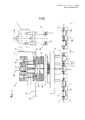
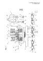
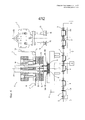
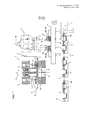
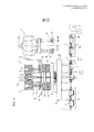
фиг. 1-9 изображают схематические виды спереди предложенной упаковочной машины для изготовления капсул в последовательности рабочих конфигураций, при этом некоторые элементы удалены для большей ясности,FIG. 1-9 depict schematic front views of the proposed capsule packaging machine in a sequence of operating configurations, with some elements removed for clarity,
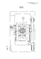
фиг. 10 изображает схематический вид сверху части машины, показанной на предыдущих чертежах, в конфигурации, изображенной на фиг. 1, при этом некоторые элементы удалены для большей ясности,FIG. 10 is a schematic top view of a part of the machine shown in the previous drawings, in the configuration shown in FIG. 1, with some elements removed for clarity,
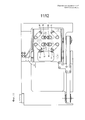
фиг. 11 изображает схематический вид сверху части, показанной на фиг. 10, в конфигурации, изображенной на фиг. 5, при этом некоторые элементы удалены для большей ясности,FIG. 11 is a schematic top view of the part shown in FIG. 10, in the configuration shown in FIG. 5, with some elements removed for clarity,
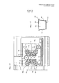
фиг. 12 изображает схематический вид снизу части, показанной на фиг. 10 и 11, при этом некоторые элементы удалены для большей ясности,FIG. 12 is a schematic bottom view of the part shown in FIG. 10 and 11, with some elements removed for clarity,
фиг. 13 изображает схематический вид сбоку в частичном разрезе капсулы, изготовленной с помощью машины, выполненной в соответствии с изобретением.FIG. 13 is a schematic partial cross-sectional side view of a capsule made with a machine made in accordance with the invention.
ПОДРОБНОЕ ОПИСАНИЕ ИЗОБРЕТЕНИЯDETAILED DESCRIPTION OF THE INVENTION
В соответствии с прилагаемыми чертежами номер 1 позиции обозначает упаковочную машину для изготовления капсул 100. Здесь и далее машина 1 описана лишь в той степени, насколько это необходимо для понимания данного изобретения.In accordance with the accompanying drawings,
В качестве примера на фиг. 13 изображена капсула 100, в целом содержащая контейнер 101, например чашеобразный, имеющий горловину 102 и дно 103, через которое происходит раздача напитка, полученного путем настаивания воды с ароматическим веществом, находящимся в контейнере и не показанным на чертежах.As an example in FIG. 13 shows a
Капсулы 100 являются одноразовыми капсулами и дополнительно содержат крышку 104, которая выполнена с возможностью пробивания и через которую может быть подана вода, и донную накладку 105, например фильтрующий элемент, в изображенном примере расположенную на дне 103 контейнера 101.
Здесь и далее для обозначения крышки 104 и/или донной накладки 105 используется общее выражение «дискообразный элемент», поскольку машина 1 предпочтительно сконструирована с обеспечением подготовки и наложения крышки 104 и накладки 105 по существу одинаковым способом.Hereinafter, the generic expression “disk-shaped element” is used to designate
В других вариантах выполнения крышка, и/или донная накладка, и/или фильтрующий элемент не являются дискообразными.In other embodiments, the cover and / or bottom plate and / or filter element are not disk-shaped.
Машина 1 содержит перемещающие средства, с помощью которых контейнеры 101 направляются вдоль заданной траектории P в направлении V подачи.
Перемещающие средства, предназначенные для перемещения контейнеров 101, содержат, например, лотки 2 и устройство для подачи лотков 2 и схематически изображены в виде блока 3.Moving means intended for moving
Каждый лоток 2 имеет гнезда 4, каждое из которых выполнено с возможностью размещения в нем соответствующего контейнера 101.Each
В изображенном предпочтительном варианте выполнения каждый лоток 2 имеет восемь гнезд 4 для такого же количества контейнеров 101.In the depicted preferred embodiment, each
Гнезда 4 расположены в лотке 2 в фиксированных заданных местоположениях, разнесенных друг от друга.
Для удобства описания ниже сделана ссылка на «расстояние разнесения» между гнездами 4 в лотке 2, что также относится к взаимному положению самих гнезд 4.For convenience of description, reference is made below to the “separation distance” between the
Машина 1 содержит перемещающие средства, с помощью которых непрерывное полотно W перемещается вдоль соответствующей заданной траектории P1 в направлении V1 подачи. Для удобства из всех средств для перемещения полотна W показан только трансмиссионный ролик 5.
Траектория P и траектория P1 по существу параллельны друг другу по меньшей мере на одном участке, как станет ясно из нижеследующего описания.The path P and the path P1 are substantially parallel to each other in at least one portion, as will become clear from the following description.
Полотно W используется для изготовления вышеуказанного дискообразного элемента 104, 105 и выполнено, например, из марли при его использовании для изготовления фильтрующих элементов 105 или из пленки при использовании для изготовления крышек 104.The web W is used for the manufacture of the aforementioned disk-
Машина 1 содержит резальную секцию 6, в которой из полотна W вырезаются дискообразные элементы 104, 105, и присоединительную секцию 7, в которой элементы 104, 105 соединяются с контейнерами 101.The
Присоединительная секция 7 выполнена отдельно от резальной секции 6 и предпочтительно расположена за ней вдоль направления V подачи контейнеров 101.The connecting section 7 is made separately from the
В соответствии с чертежами секция 6 расположена вдоль траектории P1 прохождения полотна W для обеспечения разрезания полотна W.In accordance with the drawings,
Секция 6 расположена над траекторией P прохождения контейнеров 101, в частности, по существу вдоль участка, на котором две траектории P, P1 являются параллельными.
Машина 1 содержит первые передаточные средства, с помощью которых элементы 104, 105 переносятся от секции 6 к секции 7.The
Первые передаточные средства выполнены с возможностью перемещения вдоль заданной траектории P и, более конкретно, параллельно ей.The first transmission means is arranged to move along a predetermined path P and, more specifically, parallel to it.
Первые передаточные средства выполнены с возможностью перемещения между первым рабочим положением, показанным на фиг. 1, 2, 3, 4, 8 и 9 в секции 6, и вторым рабочим положением, показанным на фиг. 6 и 7 в секции 7.The first transmission means is movable between the first operating position shown in FIG. 1, 2, 3, 4, 8, and 9 in
Более конкретно, также в соответствии с фиг. 10 и 11, первые передаточные средства содержат каретку 8, расположенную между секцией 6 и секцией 7.More specifically, also in accordance with FIG. 10 and 11, the first transmission means comprise a
Каретка 8 предпочтительно выполнена с возможностью перемещения параллельно траектории P и выполняет прямой ход в направлении V2 от секции 6 к секции 7 и обратный ход в направлении V3 от секции 7 к секции 6.The
Первые передаточные средства имеют гнезда 9, которые выполнены на каретке 8 и каждое из которых предназначено для дискообразного элемента 104, 105.The first transmission means have
Гнезда 9 выполнены с возможностью перемещения как одно целое с кареткой между первым рабочим положением для приема элементов 104, 105 в секции 6 и вторым рабочим положением для выпуска элементов 104, 105 в секции 7.The
Первые передаточные средства содержат устройство для приведения каретки 8 в действие, схематически изображенное в виде блока 10 и предназначенное для подачи каретки 8 от секции 6 к секции 7 и наоборот.The first transmission means comprise a device for driving the
На практике элементы 104, 105 вырезаются из полотна W в секции 6, а затем переносятся первыми передаточными средствами к соответствующей секции 7, в которой происходит их наложение на контейнеры 101.In practice, the
Более конкретно, элементы 104, 105 помещаются в гнезда 9 и подаются с помощью каретки 8 к секции 7.More specifically, the
При более подробном рассмотрении резальной секции 6 можно видеть, что данная секция 6 содержит средства для вырезания элементов 104, 105 и вторые средства для переноса элементов 104, 105 от секции 6 к первым передаточным средствам, в частности к гнездам 9.Upon a more detailed examination of the
На практике вторые средства для переноса элементов 104, 105 переносят элементы 104, 105 от траектории P1 к траектории P.In practice, the second means for transferring the
Вырезающие средства содержат режущие элементы 11, каждый из которых предназначен для вырезания соответствующего дискообразного элемента 104, 105.Cutting means contain
Каждый режущий элемент 11 выполнен с возможностью перемещения вдоль направления D1 резания, предпочтительно по вертикали и под прямым углом к траекториям P и P1, между поднятым исходным положением, изображенным на фиг. 1, и опущенным положением для вырезания элементов 104, 105, изображенным на фиг. 3.Each
Более конкретно, элементы 11 пересекают полотно W вдоль траектории P1, когда они находятся в опущенном положении.More specifically, the
Режущие средства содержат матричный блок 12 для полотна W, который действует совместно с режущими элементами 11 для вырезания дискообразных элементов 104, 105 и образует режущее устройство, известное также как «пуансон и матрица».The cutting means comprise a
Таким образом, при вырезании элементов 104, 105 режущее лезвие поддерживается матричным блоком с обеспечением возможности выполнения более качественных и чистых разрезов по сравнению с известными решениями.Thus, when cutting out the
Блок 12 имеет сквозные отверстия 13 для размещения и прохождения элементов 104, 105.
Вторые передаточные средства содержат захватные и подающие элементы 14, которые, например, работают с использованием всасывания и дополнительно не рассмотрены и каждый из которых предназначен для переноса соответствующего элемента 104, 105 к вышеуказанным гнездам 9, выполненным на каретке 8.The second transmission means contain gripping and feeding
Каждый элемент 14 выполнен с возможностью перемещения предпочтительно вдоль направления D1 резания между поднятым исходным положением, показанным на фиг. 1, и опущенным положением, изображенным на фиг. 4, для переноса элементов 104, 105 к соответствующему гнезду 9.Each
Предпочтительно вышеуказанные режущие элементы 11 являются трубчатыми, при этом каждый захватный элемент 14 расположен внутри соответствующего режущего элемента 11.Preferably, the
Можно видеть, что захватные элементы 14 выполнены с возможностью перемещения через отверстия 13 в блоке 12.You can see that the
В опущенном положении переноса элементы 14 расположены под трубчатыми элементами 11, находясь в опущенном положении под блоком 12.In the lowered position of the
Первые передаточные средства, в частности каретка 8 с гнездами 9, расположены под заданной траекторией P1 и под полотном W.The first transmission means, in particular the
Первые передаточные средства, в частности каретка 8 с гнездами 9, расположены над заданной траекторией P и над лотками 2.The first transfer means, in particular the
В первом рабочем положении каретка 8 расположена между режущими элементами 11 и лотками 2 в направлении D1 резания.In the first operating position, the
Присоединительная секция 7 содержит соответствующие элементы 15 для захвата и подачи элементов 104, 105, при этом каждый элемент 15 предназначен для переноса соответствующего элемента 104, 105 из гнезд 9 каретки 8 к соответствующему контейнеру 101, подаваемому лотками 2.The connecting section 7 contains corresponding
Перенос элементов 104, 105 от первых передаточных средств к контейнерам 101 происходит предпочтительно тогда, когда сами контейнеры 101 находятся в неподвижном состоянии в секции 7.The transfer of the
В соответствии с прилагаемыми чертежами захватные и удерживающие элементы 15 расположены над траекторией P, в частности над лотками 2.In accordance with the accompanying drawings, the gripping and holding
Каждый второй захватный и удерживающий элемент 15 выполнен с возможностью перемещения вдоль направления D2 наложения, предпочтительно параллельного направлению D1 резания, между поднятым исходным положением, изображенным в качестве примера на фиг. 1-4, и опущенным положением для наложения соответствующего элемента 104, 105 на соответствующий ему контейнер 101, которое изображено на фиг. 9, в частности, иллюстрирующей в качестве примера наложение донной накладки 105 в контейнере 101.Each second gripping and holding
Каждый элемент 15 может быть остановлен в промежуточном положении, изображенном на фиг. 6, между поднятым и опущенным положениями, для захвата элемента 104, 105 из соответствующего гнезда 9.Each
В одном варианте выполнения машины 1 секция 6 и секция 7 образуют часть аппарата для наложения крышки 105 на контейнер 101.In one embodiment of the
В этом случае секция 7 для присоединения крышки 105 содержит для каждого захватного элемента 15 запечатывающий элемент 16, показанный в качестве примера пунктирной линией на фиг. 1 и предназначенный для прикрепления крышки 105 к контейнеру 101.In this case, the section 7 for attaching the
Машина 1 содержит запечатывающую секцию (не показана), расположенную за секцией 7 в направлении V подачи и предназначенную для полного и окончательного герметичного присоединения крышки 105 к контейнеру 101.The
На практике запечатывающий элемент 16 временно прикрепляет крышку 105 к контейнеру 101 так, что она остается на месте до перемещения к запечатывающей секции.In practice, the sealing
Присоединение крышки 105 к контейнеру 101 в секции 7, отдельной от резальной секции, с помощью предназначенных для этого захватных и позиционирующих элементов 15, не присоединенных к режущим элементам, обеспечивает возможность вырезания крышки 105, размер которой по существу совпадает с размером наружного края горловины 102 капсулы 100, что обеспечивает возможность значительной экономии материала по сравнению с известными решениями.The attachment of the
Преимущественно использование режущего устройства типа «пуансон и матрица» обеспечивает возможность выполнения чистых, точных разрезов.Advantageously, the use of a “punch and die” type cutting device allows for clean, accurate cuts.
Запечатывание крышками в секции, отдельной от присоединительной секции, повышает качество запечатывания по сравнению с известными решениями.Sealing with covers in a section separate from the connecting section improves the quality of sealing compared to known solutions.
В предпочтительном варианте выполнения, изображенном на прилагаемых чертежах, режущие элементы 11 расположены относительно друг друга в фиксированной, заданной первой конфигурации.In the preferred embodiment depicted in the accompanying drawings, the cutting
Более конкретно, элементы 11 расположены относительно друг друга на расстоянии разнесения, отличном от расстояния разнесения между гнездами 4 в лотках 2.More specifically, the
Преимущественно элементы 11 отнесены друг от друга на меньшее расстояние, чем гнезда 4.Mostly, the
Поскольку элементы 14 для захвата дискообразных элементов 104, 105 в секции 6, как указано выше, предпочтительно выполнены с возможностью перемещения внутри режущих элементов 11, они расположены относительно друг друга в соответствии с расстоянием разнесения между указанными элементами 11.Since the
Захватные элементы 15 в секции 7 расположены относительно друг друга в соответствии с фиксированной, заданной второй конфигурацией.The
Элементы 15 расположены относительно друг друга таким образом, что каждый из них совмещен с соответствующим гнездом 4 вдоль направления D2, принимая во внимание, в частности, лоток 2, находящийся в неподвижном состоянии в секции 7.The
Средства для переноса элементов 104, 105 от секции 6 к секции 7 содержат средства для позиционирования элементов 104, 105, выполненные с возможностью перемещения между первым рабочим положением для приема элементов 104, 105 в секции 6 и вторым рабочим положением для выпуска элементов 104, 105 в секции 7.Means for transferring the
Позиционирующие средства, установленные на каретке 8, содержат вышеуказанные гнезда 9, которые в секции 6 расположены в соответствии с указанной первой конфигурацией, то есть в соответствии с положением режущих элементов 11, а в секции 7 - в соответствии с указанной второй конфигурацией, то есть в соответствии с положением захватных элементов 15.The positioning means mounted on the
Другими словами, гнезда 9 выполнены с возможностью перемещения между первой конфигурацией, которая показана на фиг. 10 и при которой каждое гнездо совмещено с соответствующим режущим элементом 11 вдоль направления D1, когда каретка 8 находится под секцией 6, и второй конфигурацией, которая показана на фиг. 11 и при которой каждое гнездо совмещено с соответствующим захватным и подающим элементом 15 вдоль направления D2, когда каретка 8 находится у секции 7.In other words, the
В варианте выполнения, изображенном, в частности, на фиг. 10 и 11, позиционирующие средства содержат подвижные элементы 17а, 17b, 17с, 17d, 17е, 17f, 17g, 17h, которые соединены с кареткой 8 и каждый из которых содержит соответствующее гнездо 9.In the embodiment shown in particular in FIG. 10 and 11, the positioning means comprise
Гнезда 9 выполнены с возможностью перемещения между первой конфигурацией и второй конфигурацией при помощи подвижных элементов 17.
Более конкретно, элементы 17 присоединены к каретке 8 с возможностью поворота относительно соответствующих осей R1, R2, R3, R4, R5, R6, R7, R8, которые параллельны друг другу и предпочтительно параллельны направлениям D1 и D2.More specifically, the elements 17 are rotatably connected to the
Вышеуказанное устройство 10 для приведения каретки 8 в действие также обеспечивает приведение элементов 17 в действие с их поворотом относительно соответствующих осей R1-R8.The
В варианте выполнения, схематически изображенном на фиг. 12, устройство 10 для приведения элементов 17 в действие содержит шкивы 18.In the embodiment schematically depicted in FIG. 12, a
Более конкретно, каждый элемент 17а, 17b, 17с, 17d, 17е, 17f, 17g, 17h установлен коаксиально с соответствующим шкивом 18а, 18b, 18с, 18d, 18е, 18f, 18g, 18h, предпочтительно расположенным на противоположной стороне каретки 8 относительно элементов 17.More specifically, each
В изображенном варианте выполнения шкивы 18а, 18с присоединены к соответствующему бесконечному ремню 19, проходящему петлей вокруг них.In the depicted embodiment, the
Шкивы 18b, 18d присоединены к соответствующему бесконечному ремню 20, проходящему петлей вокруг них.
Шкивы 18е, 18g присоединены к соответствующему бесконечному ремню 21, проходящему петлей вокруг них.
Шкивы 18f, 18h присоединены к соответствующему бесконечному ремню 22, проходящему петлей вокруг них.
Каждый ремень 19, 20, 21, 22 поддерживается в надлежаще натянутом состоянии с помощью соответствующего натяжного шкива, который не обозначен на чертежах и также образует часть приводного устройства 10.Each
Приводной ремень 23 приводит в действие шкивы 18а, 18b, 18g и 18h, которые, соответственно, являются ведомыми шкивами. Устройство 10 содержит ведущий шкив 24 для приведения в действие ремня 23.The drive belt 23 drives the
Устройство 10 обеспечивает переход гнезд 9 между первой и второй конфигурациями, в частности от первой конфигурации ко второй конфигурации при прямом ходе и от второй конфигурации к первой конфигурации при обратном ходе.The
Более конкретно, элементы 17а, 17с, 17f, 17h выполняют поворот против часовой стрелки при прямом ходе и в противоположном направлении - при обратном ходе, тогда как элементы 17b, 17d, 17е, 17g выполняют поворот по часовой стрелке при прямом ходе и в противоположном направлении - при обратном ходе.More specifically, the
Дискообразные элементы 104, 105 отнесены друг о друга на большее расстояние по сравнению с первой исходной конфигурацией в секции 6 по меньшей мере вдоль двух ортогональных направлений, одно из которых предпочтительно параллельно направлению подачи контейнеров 101.The disc-shaped
При использовании способ упаковки для изготовления капсул 100 включает этап подачи контейнеров 101 вдоль траектории P в направлении V подачи.In use, the packaging method for manufacturing
Способ включает этап вырезания дискообразных элементов 104, 105 из непрерывного полотна W, которое перемещают вдоль «траектории P1 в резальной секции 6.The method includes the step of cutting disc-shaped
Полотно W останавливают в секции 6 во время работы режущих элементов 11.The blade W is stopped in
Дискообразные элементы 104, 105 вырезают с помощью элементов 11 и подают, предпочтительно с помощью элементов 14, в гнезда 9 на каретке 8, расположенные в конфигурации, при которой они находятся близко друг к другу.The disk-shaped
Более конкретно, дискообразные элементы 104, 105 подают к гнездам 9 путем опускания элементов 14.More specifically, the disk-shaped
Каретка 8 перемещается в присоединительную секцию 7, выполненную отдельно от секции 6, и предпочтительно во время прямого хода гнезда 9 и, соответственно, дискообразные элементы 104, 105 приводят во вторую конфигурацию, при которой они разнесены на большое расстояние, то есть расположены на том же расстоянии разнесения, что и гнезда 4 на лотках 2, и на том же расстоянии разнесения, что и элементы 15, предпочтительно вследствие поворота опорных элементов 17 гнезд 9.The
В секции 7 элементы 104, 105 извлекают из гнезд 9 с помощью захватных элементов 15.In section 7,
После выполнения переноса элементы 15 опускают к элементам 104, 105, расположенным на каретке 8, и каждый из них захватывает соответствующий элемент 104, 105.After performing the transfer, the
Элементы 15 понимают элементы 104, 105 из каретки 8, которая возвращается к секции 6.
После перемещения каретки 8, как показано на фиг. 9, элементы 15 перемещаются вниз до контейнеров 101.After moving the
В проиллюстрированном случае при выполнении наложения донной накладки или фильтрующего элемента 104 элементы 15 подают по существу к дну 103 контейнера 101 для позиционирования элемента 105.In the illustrated case, when overlaying the bottom plate or
В случае наложения крышки 104 после заполнения контейнера 101 ароматическим веществом, например кофе, элемент 104 подают к горловине 102.In the case of applying the
Как указано выше, в секции 7 крышку 104 прикрепляют к контейнеру 101 с помощью заделывающего элемента 16.As indicated above, in section 7, the
Перемещение гнезд, в которых располагают донные накладки, из положения, в котором они расположены близко друг к другу, к положению, в котором они разнесены на большее расстояние, обеспечивает возможность значительного уменьшения количества состриженных отходов во время резания полотна W.Moving the nests in which the bottom plates are located, from a position in which they are located close to each other, to a position in which they are spaced a greater distance, provides the opportunity to significantly reduce the amount of sheared waste during cutting of the blade W.
Поскольку дискообразные элементы, как в случае донных накладок, так и в случае крышек, могут быть вырезаны максимально близко друг к другу независимо от расстояния разнесения между контейнерами 101, на которые накладывают дискообразные элементы, имеется возможность оптимизации использования материала полотна W.Since the disk-shaped elements, both in the case of bottom pads and in the case of covers, can be cut as close as possible to each other, regardless of the separation distance between the
Claims (37)
Applications Claiming Priority (3)
| Application Number | Priority Date | Filing Date | Title |
|---|---|---|---|
| ITBO2013A000390 | 2013-07-23 | ||
| IT000390A ITBO20130390A1 (en) | 2013-07-23 | 2013-07-23 | MACHINE AND METHOD FOR PACKAGING CAPSULES. |
| PCT/IB2014/063344 WO2015011657A1 (en) | 2013-07-23 | 2014-07-23 | Packaging machine and method for making capsules |
Publications (3)
| Publication Number | Publication Date |
|---|---|
| RU2016101044A RU2016101044A (en) | 2017-08-28 |
| RU2016101044A3 RU2016101044A3 (en) | 2018-03-01 |
| RU2651283C2 true RU2651283C2 (en) | 2018-04-19 |
Family
ID=49261599
Family Applications (1)
| Application Number | Title | Priority Date | Filing Date |
|---|---|---|---|
| RU2016101044A RU2651283C2 (en) | 2013-07-23 | 2014-07-23 | Packaging machine and method for making capsules |
Country Status (8)
| Country | Link |
|---|---|
| US (2) | US10358240B2 (en) |
| EP (1) | EP3024734B1 (en) |
| KR (1) | KR102251249B1 (en) |
| CN (1) | CN105408211B (en) |
| BR (1) | BR112016001481B1 (en) |
| IT (1) | ITBO20130390A1 (en) |
| RU (1) | RU2651283C2 (en) |
| WO (1) | WO2015011657A1 (en) |
Families Citing this family (16)
| Publication number | Priority date | Publication date | Assignee | Title |
|---|---|---|---|---|
| ITBO20130390A1 (en) * | 2013-07-23 | 2015-01-24 | Azionaria Costruzioni Acma Spa | MACHINE AND METHOD FOR PACKAGING CAPSULES. |
| US10472105B2 (en) * | 2014-05-22 | 2019-11-12 | Gima S.P.A. | Unit for feeding closing elements designed to close cup-shaped containers, station and method for closing the cup-shaped containers |
| ITUB20152469A1 (en) * | 2015-07-24 | 2017-01-24 | Marco Verri | EQUIPMENT FOR THE PRODUCTION OF A PRODUCT, PREFERABLY OF A FOOD PRODUCT TO REALIZE A DRINK THROUGH INFUSION IN A LIQUID RESPECTIVE |
| US10925430B2 (en) * | 2015-11-23 | 2021-02-23 | Mb2 Cup Development Llc | System, apparatus, and method for preparing a beverage cartridge |
| US11745906B2 (en) * | 2015-11-23 | 2023-09-05 | Cupper Llc | System, apparatus, and method for preparing a beverage cartridge |
| US20220361705A1 (en) * | 2015-11-23 | 2022-11-17 | Cupper, Llc | System, apparatus and method for preparing a beverage cartridge |
| IT201600071546A1 (en) | 2016-07-11 | 2018-01-11 | Azionaria Costruzioni Acma Spa | Hermetic closure device for food product containment packages. |
| IT201600103666A1 (en) * | 2016-10-14 | 2018-04-14 | Cryovac Inc | EQUIPMENT AND METHOD OF PACKAGING A PRODUCT |
| IT201800009195A1 (en) * | 2018-10-05 | 2020-04-05 | Omas Tecnosistemi Spa | CAPSULES PACKAGING PLANT |
| IT201800010250A1 (en) * | 2018-11-12 | 2020-05-12 | Opem S P A | APPARATUS FOR THE PACKAGING OF CAPSULES IN VACUUM |
| IT201800011153A1 (en) | 2018-12-17 | 2020-06-17 | Azionaria Costruzioni Acma Spa | DEVICE FOR TREATMENT OF A CONTINUOUS BELT |
| IT201900003631A1 (en) * | 2019-03-13 | 2020-09-13 | Sarong Spa | Beverage capsule processing plant |
| CN109866432B (en) * | 2019-04-15 | 2024-02-27 | 宁波锦宇电器有限公司 | Machine for making coffee capsules |
| IT201900013965A1 (en) * | 2019-08-05 | 2021-02-05 | Ima Spa | Machine for making capsules. |
| CA3183610A1 (en) * | 2020-08-05 | 2022-02-10 | G.D S.P.A. | Transfer device and process |
| BR112023001270A2 (en) * | 2020-08-05 | 2023-04-04 | Gd Spa | TRANSFER DEVICE AND PROCESS, AND PACKAGING APPLIANCE |
Citations (4)
| Publication number | Priority date | Publication date | Assignee | Title |
|---|---|---|---|---|
| SU1405697A3 (en) * | 1983-05-19 | 1988-06-23 | Эсселте Пак Актиеболаг (Фирма) | Arrangement for shaping and installing cover into tubular container |
| FR2827835A1 (en) * | 2001-07-26 | 2003-01-31 | Erca Formseal | Device for cutting row of protective caps and fixing them on containers comprises step by step advancement of cap band above rows of containers, cutting tools and suction pads |
| DE102007053034A1 (en) * | 2007-11-07 | 2009-05-14 | Robert Bosch Gmbh | Containers filling device for filling e.g. coffee powder, has thermoforming device with transporting device serving as integral part, where uninterrupted sequence is executed from forming of container till filling of container |
| WO2013064988A1 (en) * | 2011-11-04 | 2013-05-10 | Ima Industries S.R.L. | Method and machine for producing a single-use capsule for beverages and capsule obtained using method |
Family Cites Families (23)
| Publication number | Priority date | Publication date | Assignee | Title |
|---|---|---|---|---|
| NO161311C (en) * | 1983-02-24 | 1989-08-02 | Reinhard Goepfert | Self-propelled device for lifting and moving elements to be lifted. |
| US4625498A (en) * | 1985-03-25 | 1986-12-02 | Sealright Co., Inc. | Apparatus for applying recessed membrane seals to containers |
| US4682463A (en) * | 1985-09-03 | 1987-07-28 | Montreal Milling Cutter Company | Apparatus for forming and attaching a flexible foil sealing disk |
| US5108768A (en) * | 1988-11-25 | 1992-04-28 | So Peter K L | Cartridge for beverage making |
| IT1293236B1 (en) * | 1997-07-09 | 1999-02-16 | Gd Spa | METHOD AND UNIT FEEDING OF COLLARS FOR RIGID CIGARETTES PACKAGES TO A CONTINUOUS PACKAGING LINE. |
| DE19817737A1 (en) * | 1998-04-21 | 1999-11-04 | Hassia Verpackung Ag | Deep-drawn cup and process for its manufacture |
| US6439631B1 (en) * | 2000-03-03 | 2002-08-27 | Micron Technology, Inc. | Variable-pitch pick and place device |
| US6440256B1 (en) * | 2000-06-20 | 2002-08-27 | Keurig, Incorporated | Method of forming and inserting filter elements in cup-shaped containers |
| GB0209316D0 (en) * | 2002-04-24 | 2002-06-05 | Relco Uk Ltd | Cutting device |
| ES2309874T3 (en) * | 2006-07-26 | 2008-12-16 | INDAG GESELLSCHAFT FUR INDUSTRIEBEDARF MBH & CO. BETRIEBS KG | PRESSOR DEVICE. |
| US7910145B2 (en) * | 2007-05-31 | 2011-03-22 | Marco Reati | Precharged ground coffee capsule, method for its production and apparatus for implementing said method |
| SE531357C2 (en) * | 2007-09-28 | 2009-03-10 | Ecolean Res & Dev As | Device and method for handling a package |
| SE0702169L (en) * | 2007-09-28 | 2009-03-10 | Ecolean Res & Dev As | Method and apparatus for filling packages of collapsing kind |
| US8407973B2 (en) * | 2009-07-29 | 2013-04-02 | General Mills, Inc. | Food packaging with vertical to horizontal transfer loading |
| US20120204516A1 (en) * | 2009-07-29 | 2012-08-16 | Cryovac, Inc. | Vacuum Skin Packaging of a Product Arranged on a Support |
| DE102010009536A1 (en) * | 2010-02-26 | 2011-09-01 | Cfs Germany Gmbh | Method for changing the upper and lower tool of a packaging machine |
| EP2853357B2 (en) * | 2011-03-16 | 2023-01-25 | Cama1 S.p.A. | Machine and method for cartoning articles |
| WO2013134885A1 (en) * | 2012-03-15 | 2013-09-19 | Rychiger Ag | Apparatus and method for manufacturing filters and inserting the filters into single dose capsules for preparing beverages |
| ITBO20120170A1 (en) * | 2012-03-29 | 2013-09-30 | Ima Ind Srl | MACHINE AND PROCEDURE FOR THE FORMATION OF DISPOSABLE DRINKS FOR DRINKS |
| DE102012105282A1 (en) * | 2012-06-18 | 2013-12-19 | K-Fee System Gmbh | Portion capsule and method of making a beverage with a portion capsule |
| EP2730523B1 (en) * | 2012-11-12 | 2016-04-06 | 2266170 Ontario, Inc. | Beverage capsule and process and system for making same |
| NZ736438A (en) * | 2013-04-09 | 2019-06-28 | Cryovac Llc | Process and system of supplying film sheets to a packaging assembly of a packaging apparatus |
| ITBO20130390A1 (en) * | 2013-07-23 | 2015-01-24 | Azionaria Costruzioni Acma Spa | MACHINE AND METHOD FOR PACKAGING CAPSULES. |
-
2013
- 2013-07-23 IT IT000390A patent/ITBO20130390A1/en unknown
-
2014
- 2014-07-23 EP EP14777165.3A patent/EP3024734B1/en active Active
- 2014-07-23 RU RU2016101044A patent/RU2651283C2/en active
- 2014-07-23 CN CN201480041716.4A patent/CN105408211B/en active Active
- 2014-07-23 KR KR1020167004441A patent/KR102251249B1/en active IP Right Grant
- 2014-07-23 BR BR112016001481-2A patent/BR112016001481B1/en active IP Right Grant
- 2014-07-23 US US14/904,913 patent/US10358240B2/en active Active
- 2014-07-23 WO PCT/IB2014/063344 patent/WO2015011657A1/en active Application Filing
-
2019
- 2019-05-28 US US16/423,911 patent/US11325732B2/en active Active
Patent Citations (4)
| Publication number | Priority date | Publication date | Assignee | Title |
|---|---|---|---|---|
| SU1405697A3 (en) * | 1983-05-19 | 1988-06-23 | Эсселте Пак Актиеболаг (Фирма) | Arrangement for shaping and installing cover into tubular container |
| FR2827835A1 (en) * | 2001-07-26 | 2003-01-31 | Erca Formseal | Device for cutting row of protective caps and fixing them on containers comprises step by step advancement of cap band above rows of containers, cutting tools and suction pads |
| DE102007053034A1 (en) * | 2007-11-07 | 2009-05-14 | Robert Bosch Gmbh | Containers filling device for filling e.g. coffee powder, has thermoforming device with transporting device serving as integral part, where uninterrupted sequence is executed from forming of container till filling of container |
| WO2013064988A1 (en) * | 2011-11-04 | 2013-05-10 | Ima Industries S.R.L. | Method and machine for producing a single-use capsule for beverages and capsule obtained using method |
Also Published As
| Publication number | Publication date |
|---|---|
| WO2015011657A1 (en) | 2015-01-29 |
| KR102251249B1 (en) | 2021-05-13 |
| RU2016101044A3 (en) | 2018-03-01 |
| KR20160034993A (en) | 2016-03-30 |
| US11325732B2 (en) | 2022-05-10 |
| US20160144987A1 (en) | 2016-05-26 |
| EP3024734B1 (en) | 2017-09-20 |
| CN105408211A (en) | 2016-03-16 |
| EP3024734A1 (en) | 2016-06-01 |
| ITBO20130390A1 (en) | 2015-01-24 |
| US10358240B2 (en) | 2019-07-23 |
| BR112016001481B1 (en) | 2021-09-21 |
| BR112016001481A2 (en) | 2017-07-25 |
| RU2016101044A (en) | 2017-08-28 |
| US20190276172A1 (en) | 2019-09-12 |
| CN105408211B (en) | 2018-11-30 |
Similar Documents
| Publication | Publication Date | Title |
|---|---|---|
| RU2651283C2 (en) | Packaging machine and method for making capsules | |
| CN103402875B (en) | For the manufacture of there is immersion product and there is the machine of the filter bag of outer wrapping big envelope | |
| CN106114962A (en) | Fructus Mali pumilae set net packer and operational approach thereof | |
| US20130212988A1 (en) | Method for Changing the Upper and Lower Tool of a Packaging Machine | |
| CN205872601U (en) | Apple cover net packagine machine | |
| TW201442921A (en) | Beverage capsule machine for making single use beverage capsules | |
| US9056693B2 (en) | Machine for placing protective dividers of bottles contained in packaging boxes | |
| CN102009754B (en) | Capping device for drink outlet of high-capacity rectangular or square package box | |
| CN104787389B (en) | Bagging apparatus on bean noodles automatic packaging machine | |
| CN106144027A (en) | To chartered plane in folded film | |
| US20130209207A1 (en) | Tray filling machine | |
| US3703066A (en) | Apparatus for feeding heat shrinkable plastic film and capping containers therewith | |
| CN102717918A (en) | Automatic packing machine for toothpicks | |
| US6615882B1 (en) | Filling device of a dual layered filling and packing device | |
| CN205467785U (en) | Full -automatic film laminating machine | |
| KR101574271B1 (en) | A rotary type packing machine | |
| CN102826265B (en) | Manipulator unit and production line with same | |
| JP2023536309A (en) | Packaging equipment and processes | |
| CN205418273U (en) | Aluminium foil sealing label mechanism during plastic bottle packs with metal bottle lid and liquid filling machine thereof | |
| CN203439307U (en) | Packaging machine | |
| CN103466137B (en) | Food packaging processes | |
| CN106965245B (en) | A kind of electronic bill back segment process equipment | |
| US3452512A (en) | Apparatus for packaging | |
| CN211943912U (en) | Packing plant is used in shoes production and processing | |
| USRE28584E (en) | Apparatus for feeding heat shrinkable plastic film and capping containers therewith |