EP3024734B1 - Packaging machine and method for making capsules - Google Patents
Packaging machine and method for making capsules Download PDFInfo
- Publication number
- EP3024734B1 EP3024734B1 EP14777165.3A EP14777165A EP3024734B1 EP 3024734 B1 EP3024734 B1 EP 3024734B1 EP 14777165 A EP14777165 A EP 14777165A EP 3024734 B1 EP3024734 B1 EP 3024734B1
- Authority
- EP
- European Patent Office
- Prior art keywords
- disc
- station
- shaped elements
- associating
- elements
- Prior art date
- Legal status (The legal status is an assumption and is not a legal conclusion. Google has not performed a legal analysis and makes no representation as to the accuracy of the status listed.)
- Active
Links
- 239000002775 capsule Substances 0.000 title claims description 23
- 238000000034 method Methods 0.000 title claims description 16
- 238000004806 packaging method and process Methods 0.000 title claims description 15
- 238000007789 sealing Methods 0.000 claims description 6
- 125000003118 aryl group Chemical group 0.000 description 5
- 239000000463 material Substances 0.000 description 5
- 239000000126 substance Substances 0.000 description 5
- XLYOFNOQVPJJNP-UHFFFAOYSA-N water Substances O XLYOFNOQVPJJNP-UHFFFAOYSA-N 0.000 description 4
- 238000001802 infusion Methods 0.000 description 3
- 239000002699 waste material Substances 0.000 description 3
- 235000013361 beverage Nutrition 0.000 description 2
- 230000000694 effects Effects 0.000 description 2
- 230000005540 biological transmission Effects 0.000 description 1
- 230000015572 biosynthetic process Effects 0.000 description 1
- 235000014121 butter Nutrition 0.000 description 1
Images


Classifications
-
- B—PERFORMING OPERATIONS; TRANSPORTING
- B65—CONVEYING; PACKING; STORING; HANDLING THIN OR FILAMENTARY MATERIAL
- B65B—MACHINES, APPARATUS OR DEVICES FOR, OR METHODS OF, PACKAGING ARTICLES OR MATERIALS; UNPACKING
- B65B29/00—Packaging of materials presenting special problems
- B65B29/02—Packaging of substances, e.g. tea, which are intended to be infused in the package
- B65B29/022—Packaging of substances, e.g. tea, which are intended to be infused in the package packaging infusion material into capsules
-
- B—PERFORMING OPERATIONS; TRANSPORTING
- B65—CONVEYING; PACKING; STORING; HANDLING THIN OR FILAMENTARY MATERIAL
- B65B—MACHINES, APPARATUS OR DEVICES FOR, OR METHODS OF, PACKAGING ARTICLES OR MATERIALS; UNPACKING
- B65B61/00—Auxiliary devices, not otherwise provided for, for operating on sheets, blanks, webs, binding material, containers or packages
- B65B61/005—Auxiliary devices, not otherwise provided for, for operating on sheets, blanks, webs, binding material, containers or packages for removing material by cutting
-
- B—PERFORMING OPERATIONS; TRANSPORTING
- B65—CONVEYING; PACKING; STORING; HANDLING THIN OR FILAMENTARY MATERIAL
- B65B—MACHINES, APPARATUS OR DEVICES FOR, OR METHODS OF, PACKAGING ARTICLES OR MATERIALS; UNPACKING
- B65B7/00—Closing containers or receptacles after filling
- B65B7/01—Machines characterised by incorporation of means for making the closures before applying
Definitions
- This invention relates to a packaging machine and a packaging method for making capsules containing aromatic substances for preparing infusions.
- the reference capsules are single-use capsules basically comprising a container, for example cup-shaped, provided with a perforatable lid through which water can be fed, and a bottom through which is dispensed the beverage produced by effect of the infusion of the water with an aromatic substance present in the container.
- Prior art packaging machines for making capsules comprise, very briefly, a conveying line for moving the containers along a predetermined path in a feed direction.
- a system In a first station along the feed path is located a system, where provided, for feeding a continuous web of sheet material which is located at least partly above the container conveying line and from which capsule bottom linings are cut and inserted into the containers.
- each bottom lining is cut from the web, fed downwardly and inserted into the respective container.
- the bottom lining is sealed to the container.
- the containers are filled with a suitably measured quantity of the aromatic substance.
- prior art machines Downstream of the filling station along the feed direction, prior art machines comprise a station for closing the capsules where a cover is applied to each container.
- the closing station is normally provided with a system for feeding a continuous web of film, which is located at least partly above the container conveying line and from which the covers are cut and applied to the mouth at the top of each container.
- each cover is cut from the web, fed downwardly and applied and sealed to the respective container.
- the above mentioned operations are performed by actuator means equipped with knives for cutting the covers or the bottom linings, with pickup elements for holding the covers or the bottom linings and, if necessary, with sealers.
- the actuator means spaced at the same spacing as the containers being processed, each basically comprise a rod movable between a raised position and a lowered position for applying/positioning the bottom lining or the cover in or on the container. At a position intermediate between the end positions, as mentioned, the bottom lining or the cover is cut from the respective continuous web.
- the actuator means for cutting and positioning the covers and, if necessary, the bottom linings are, as already mentioned, spaced at the same spacing as the containers.
- the main technical purpose of this invention is to propose a packaging machine and method for making capsules which are free of the above mentioned disadvantages.
- One aim of this invention is to provide a packaging machine and method for making capsules which allow reducing the amount of material used in particular for the covers.
- a further aim of the invention is to provide a packaging machine for making capsules where the amount of waste offcuts resulting from cutting the webs for the covers and/or the bottom linings is reduced.
- the technical purpose and aims specified are substantially achieved by a packaging machine for making capsules according to claim 1 and by a packaging method for making capsules according to claim 21.
- the numeral 1 denotes a packaging machine for making capsules 100.
- the machine 1 is hereinafter described only insofar as necessary for understanding this invention.
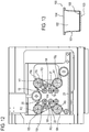
- Figure 13 shows a capsule 100 basically comprising a container 101, for example cup-shaped, provided with a mouth 102 and a bottom 103 through which is dispensed the beverage produced by effect of the infusion of the water with an aromatic substance present in the container and not illustrated.
- the reference capsules 100 are single-use capsules and further comprise a perforatable cover 104 through which water can be fed, and a bottom lining 105, for example a filter element, positioned, in the example illustrated, on the bottom 103 of the container 101.
- the term "disc-shaped element” is used generically to denote the cover 104 and/or the bottom lining 105, since the machine 1 is preferably structured to prepare and apply both the cover 104 and the bottom lining 105 in substantially the same way.
- cover and/or the bottom lining and/or the filter element are not disc-shaped.
- the machine 1 comprises movement means by which the containers 101 are directed along a predetermined path P in a feed direction V.
- the movement means for moving the containers 101 comprise, for example, a plurality of trays 2 and a system for feeding the trays 2 and schematically represented as a block 3.
- Each tray 2 is provided with a plurality of pockets 4, each designed to receive a respective container 101.
- each tray 2 comprises eight pockets 4 for as many containers 101.
- the pockets 4 are located on the tray 2 at fixed, predetermined positions suitably spaced from each other.
- the machine 1 comprises movement means by which a continuous web W is moved along a respective predetermined path P1 in a feed direction V1.
- movement means for moving the web W only a transmission roller 5 is, for convenience, illustrated.
- the path P and the path P1 are substantially parallel to each other along at least one stretch, as will become clearer as this description continues.
- the web W is used to make the aforementioned disc-shaped element 104, 105 and is, for example, of butter muslin if used to make the filter elements 105 or of film if used to make the covers 104.
- the machine 1 comprises a cutoff station 6 where the disc-shaped elements 104, 105 are cut from the web W and an associating station 7 where the disc-shaped elements 104, 105 are associated with the containers 101.
- the associating station 7 is distinct from the cutoff station 6 and is preferably located downstream thereof along the feed direction V of the containers 101.
- the cutoff station 6 is located along the path P1 of the web W to cut the web W.
- the station 6 is located above the feed path P of the containers 101, in particular substantially along the stretch where the two paths P, P1 are parallel.
- the machine 1 comprises first transfer means by which the disc-shaped elements 104, 105 are transferred from the cutoff station 6 to the associating station 7.
- the first transfer means are movable along the predetermined path P, and more specifically, parallel thereto.
- the first transfer means are movable between a first operating position, illustrated in Figures 1 , 2 , 3 , 4 , 8 , 9 at the cutoff station 6, and a second operating position, illustrated in Figures 6 , 7 , at the associating station 7. More specifically, also with reference to Figures 10 and 11 , the first transfer means comprise a carriage 8 between the cutoff station 6 and the associating station 7.
- the carriage 8 is preferably movable parallel to the path P and performs a forward stroke in a direction V2 from the cutoff station 6 to the associating station 7 and a return stroke in a direction V3 from the associating station 7 to the cutoff station 6.
- the first transfer means comprise a plurality of pockets 9, each for a disc-shaped element 104, 105, provided on the carriage 8.
- the pockets 9 are movable as one with the carriage between a first operating position for receiving the disc-shaped elements 104, 105 at the cutoff station 6 and a second operating position for releasing the disc-shaped elements 104, 105 at the associating station 7.
- the first transfer means comprise a system for driving the carriage 8, schematically represented as a block 10, for feeding the carriage 8 from the cutoff station 6 to the associating station 7 and vice versa.
- the disc-shaped elements 104, 105 are cut from the web W at the cutoff station 6 and then transferred by the first transfer means to the corresponding associating station 7 where they are applied to the containers 101.
- the disc-shaped elements 104, 105 are placed in the pockets 9 and fed by the carriage 8 to the associating station 7.
- this station 6 comprises means for cutting the disc-shaped elements 104, 105 and second means for transferring the disc-shaped elements 104, 105 from the cutoff station 6 to the first transfer means, and more specifically, to the pockets 9.
- the second means for transferring the disc-shaped elements 104, 105 transfer the disc-shaped elements 104, 105 from the path P1 to the path P.
- the cutting means comprise a plurality of cutters 11 each for cutting a corresponding disc-shaped element 104, 105.
- Each cutter 11 is movable along a cutting direction D1, preferably vertical and at right angles to the paths P and P1, between a raised, rest position, illustrated in Figure 1 , and a lowered position for cutting the disc-shaped elements 104, 105, illustrated in Figure 3 .
- the cutters 11 intercept the web W along the path P1 when they are at the lowered position.
- the cutting means comprise a die block 12 for the web W which acts in conjunction with the cutters 11 to cut the disc-shaped elements 104, 105 and which defines a cutting system known also as "punch and die".
- a cutting system known also as "punch and die”.
- the die block 12 has a plurality of through holes 13 for the receiving and transit of the disc-shaped elements 104, 105.
- the second transfer means comprise a plurality of pickup and feed elements 14, for example operating by suction, not further described, each for transferring a corresponding disc-shaped element 104, 105 to the aforementioned pockets 9 provided on the carriage 8.
- Each element 14 is movable, preferably along the cutting direction D1, between a raised, rest position, illustrated in Figure 1 , and a lowered position for transferring the disc-shaped element 104, 105, illustrated in Figure 4 , to the respective pocket 9.
- the aforementioned cutters 11 are tubular and each pickup element 14 is located inside a corresponding cutter 11.
- the pickup elements 14 are movable through the holes 13 in the die block 12.
- the pickup elements 14 are located below the tubular cutters 11 at the lowered position and below the die block 12.
- the first transfer means in particular the carriage 8 with the pockets 9, are located below the predetermined path P1 and below the web W.
- the first transfer means in particular the carriage 8 with the pockets 9, are located above the predetermined path P and above the trays 2.
- the carriage 8 is interposed between the cutters 11 and the trays 2 in the cutting direction D1.
- the associating station 7 comprises respective elements 15 for picking up and feeding the disc-shaped elements 104, 105" each for transferring a corresponding disc-shaped element 104, 105 from the pockets 9 of the carriage 8 to a corresponding container 101 fed by the trays 2.
- the transfer of the disc-shaped element 104, 105 from the first transfer means to the containers 101 occurs preferably when the containers 101 themselves are stationary at the station 7.
- the pickup and retaining elements 15 are located above the path P and, in particular, above the trays 2.
- Each second pickup and retaining element 15 is movable along an application direction D2, preferably parallel to the cutting direction D1, between a raised, rest position, illustrated by way of example in Figures 1 to 4 , and a lowered position for applying the corresponding disc-shaped element 104, 105 to the respective container 101, illustrated in Figure 9 , which in particular shows by way of an example the application of the bottom lining 105 in the container 101.
- Each element 15 can be stopped at an intermediate position, illustrated in Figure 6 , between the raised and the lowered position, for picking up the disc-shaped element 104, 105 from the respective pockets 9.
- the station 6 and the station 7 form part of an apparatus for applying the cover 105 to the container 101.
- the station 7 for associating the cover 105 comprises a sealer 16, illustrated by way of example by a dashed line in Figure 1 , for each pickup element 15, to attach the cover 105 to the container 101.
- the machine 1 comprises a sealing station, not illustrated, located downstream of the associating station 7 in the feed direction V, for completely and definitively sealing the cover 105 to the container 101.
- the sealer 16 temporarily attaches the cover 105 to the container 101 so it remains in position until transfer to the sealing station.
- Sealing the covers at a station distinct from the associating station improves the quality of the seal compared to prior art solutions.
- the cutters 11 are positioned relative to each other in a fixed, predetermined first configuration.
- the cutters 11 are positioned relative to each other according to a spacing which is different from the spacing of the pockets 4 in the trays 2.
- the cutters 11 are spaced more closely together than the pockets 4 are.
- the elements 14 for picking up the disc-shaped elements 104, 105 in the station 6 are, as mentioned above, preferably slidable inside the cutters 11, they are positioned relative to each other according to the spacing thereof.
- the pickup elements 15 in the station 7 are positioned relative to each other according to a fixed, predetermined second configuration.
- the elements 15 are positioned relative to each other in such a way that each is aligned with a corresponding pocket 4 along the application direction D2, considering in particular a tray 2 which is stationary at the station 7.
- the means for transferring the disc-shaped elements 104, 105 from the station 6 to the station 7 comprise means for positioning the disc-shaped elements 104, 105 movable between a first operating position for receiving the disc-shaped elements 104, 105 in the station 6 and a second operating position for releasing the disc-shaped elements 104, 105 in the station 7.
- the positioning means mounted on the carriage 8, comprise the aforementioned pockets 9 which, in the cutoff station 6, are positioned according to the first configuration, that is according to the position of the cutters 11, and, in the associating station 7, according to the second configuration, that is, according to the position of the pickup elements 15.
- the pockets 9 are movable between the first configuration, illustrated in Figure 10 , where each is aligned with a corresponding cutter 11 along the cutting direction D1 when the carriage 8 is under the cutoff station 6, and the second configuration, illustrated in Figure 11 , where each is aligned with a corresponding pickup and feed element 15 along the application direction D2 when the carriage 8 is at the associating station 7.
- the positioning means comprise a plurality of movable elements 17a, 17b, 17c, 17d, 17e, 17f, 17g, 17h associated with the carriage 8, each bearing a respective pocket 9,
- the pockets 9 are movable between the first configuration and the second configuration through the agency of the movable elements 17.
- the elements 17 are rotatably connected to the carriage 8 and are rotatable about respective axes R1, R2, R3, R4, R5, R6, R7, R8 which are parallel to each other and preferably parallel to the directions D1 and D2.
- the aforementioned system 10 for driving the carriage 8 is configured to also drive the elements 17 in rotation about the respective axes R1-R8.
- the system 10 for driving the elements 17 comprises a plurality of pulleys 18.
- each element 17a, 17b, 17c, 17d, 17e, 17f, 17g, 17h is mounted coaxially with a respective pulley 18a, 18b, 18c, 18d, 18e, 18f, 18g, 18h, which are preferably located on the side of the carriage 8 opposite to the elements 17.
- the pulleys 18a, 18c are connected to a respective endless belt 19 looped around them.
- the pulleys 18b, 18d are connected to a respective endless belt 20 looped around them.
- the pulleys 18e, 18g are connected to a respective endless belt 21 looped around them.
- the pulleys 18f, 18h are connected to a respective endless belt 22 looped around them.
- Each belt 19, 20, 21, 22 is kept suitably tensioned by a respective tensioning pulley which is not labelled and which also forms part of the drive system 10.
- a drive belt 23 drives the pulleys 18a, 18b, 18g and 18h, which are thus driven pulleys.
- the drive system 10 comprises a drive pulley 24 for driving the belt 23.
- the system 10 drives the pockets 9 between the first and the second configuration, in particular from the first configuration to the second in the forward stroke and from the second configuration to the first in the return stroke.
- the elements 17a, 17c, 17f, 17h perform an anticlockwise rotation in the forward stroke and vice versa in the return stroke, while the elements 17b, 17d, 17e, 17g perform a clockwise rotation in the forward stroke and vice versa in the return stroke.
- the disc-shaped elements 104, 105 are further spaced from each other compared to the first starting configuration at the cutoff station 6 at least along two orthogonal directions of which one is preferably parallel to the feed direction of the containers 101.
- the packaging method for making the capsules 100 comprises a step of feeding the containers 101 along the path P in the feed direction V.
- the method comprises a step of cutting the disc-shaped elements 104, 105 from the continuous web W which is movable along the path P1 in the cutoff station 6
- the web W is stopped in the cutoff station 6 during the action of the cutters 11.
- the disc-shaped elements 104, 105 are cut by the cutters 11 and fed, preferably by the elements 14, into the pockets 9 on the carriage 8 positioned in the configuration where they are close to each other.
- the disc-shaped elements 104, 105 are fed to the pockets 9 by lowering the elements 14.
- the carriage 8 moves into the associating station 7, distinct from the cutoff station 6, and preferably during the forward stroke, the pockets 9, and hence the disc-shaped elements 104, 105, are brought to the second configuration where they are far apart, that is, positioned at the same spacing as the pockets 4 on the trays 2 and at the same spacing as the pickup and feed elements 15, preferably by a rotation of the supporting elements 17 of the pockets 9.
- the disc-shaped elements 104, 105 are withdrawn from the pockets 9 by the pickup elements 15.
- the pickup elements 15 are lowered to the disc-shaped elements 104, 105 on the carriage 8 and each grips a corresponding disc-shaped element 104, 105.
- the pickup elements 15 lift the disc-shaped elements 104, 105 out of the carriage 8 which returns to the cutoff station 6.
- the elements 15 are fed substantially as far as the bottom 103 of the container 101 in order to position the disc-shaped element 105.
- the disc-shaped element 104 is fed as far as the mouth 102.
- the cover 104 is attached to the container 101 by means of the sealer 16.
- the disc-shaped elements both in the case of the bottom linings and the covers, can be cut off as closely to each other as possible, irrespective of the spacing of the containers 101 which the disc-shaped elements will be applied to, it is possible to optimize the use of the material of the web W.
Description
- This invention relates to a packaging machine and a packaging method for making capsules containing aromatic substances for preparing infusions.
- The reference capsules are single-use capsules basically comprising a container, for example cup-shaped, provided with a perforatable lid through which water can be fed, and a bottom through which is dispensed the beverage produced by effect of the infusion of the water with an aromatic substance present in the container.
- Prior art packaging machines for making capsules comprise, very briefly, a conveying line for moving the containers along a predetermined path in a feed direction.
- In a first station along the feed path is located a system, where provided, for feeding a continuous web of sheet material which is located at least partly above the container conveying line and from which capsule bottom linings are cut and inserted into the containers.
- In this station, each bottom lining is cut from the web, fed downwardly and inserted into the respective container. Where provided, in the same station, the bottom lining is sealed to the container.
- Next, in a filling station, the containers are filled with a suitably measured quantity of the aromatic substance.
- Downstream of the filling station along the feed direction, prior art machines comprise a station for closing the capsules where a cover is applied to each container.
- In substantially the same way as with the bottom linings, the closing station is normally provided with a system for feeding a continuous web of film, which is located at least partly above the container conveying line and from which the covers are cut and applied to the mouth at the top of each container.
- In this station, each cover is cut from the web, fed downwardly and applied and sealed to the respective container.
- Generally speaking, to apply both the covers and, if provided, the bottom linings, the above mentioned operations are performed by actuator means equipped with knives for cutting the covers or the bottom linings, with pickup elements for holding the covers or the bottom linings and, if necessary, with sealers. The actuator means, spaced at the same spacing as the containers being processed, each basically comprise a rod movable between a raised position and a lowered position for applying/positioning the bottom lining or the cover in or on the container. At a position intermediate between the end positions, as mentioned, the bottom lining or the cover is cut from the respective continuous web.
- In the specific case of the covers, since the same actuator element has to cut, position and seal the cover, the latter has to be cut to a size much larger than the size of the mouth at the top of the container, which means that much more material is used than is actually necessary to close the container.
- Also, since the spacing and relative position of the containers on the line is substantially dictated by constructional requirements, the actuator means for cutting and positioning the covers and, if necessary, the bottom linings are, as already mentioned, spaced at the same spacing as the containers.
- This configuration leads to the formation of large amounts of waste offcuts from the webs from which the covers and the bottom linings are cut.
- In this context, the main technical purpose of this invention is to propose a packaging machine and method for making capsules which are free of the above mentioned disadvantages.
- Document
WO2013/064988A1 discloses the features of the preamble ofclaims - One aim of this invention is to provide a packaging machine and method for making capsules which allow reducing the amount of material used in particular for the covers.
- A further aim of the invention is to provide a packaging machine for making capsules where the amount of waste offcuts resulting from cutting the webs for the covers and/or the bottom linings is reduced.
- The technical purpose and aims specified are substantially achieved by a packaging machine for making capsules according to
claim 1 and by a packaging method for making capsules according toclaim 21. - Further features of the invention and its advantages are more apparent in the non-limiting description below, with reference to a preferred but non-exclusive embodiment of a packaging machine for making capsules, as illustrated in the accompanying drawings, in which:
-
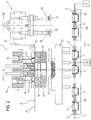
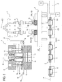
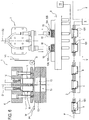
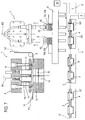
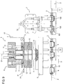
Figures 1 to 9 illustrate a packaging machine for making capsules according to this invention in schematic front views with some parts cut away for greater clarity and in a sequence of operating configurations; -
Figure 10 illustrates a detail of the machine of the preceding figures in the configuration ofFigure 1 in a schematic top plan view with some parts cut away for greater clarity; -
Figure 11 illustrates the detail ofFigure 10 in the configuration ofFigure 5 in a schematic top plan view with some parts cut away for greater clarity; -
Figure 12 illustrates the detail ofFigures 10 and11 in a schematic bottom plan view with some parts cut away for greater clarity; -
Figure 13 illustrates a capsule made with a machine according to the invention in a schematic side view partly in cross section. - With reference to the accompanying drawings, the
numeral 1 denotes a packaging machine for makingcapsules 100. Themachine 1 is hereinafter described only insofar as necessary for understanding this invention. - By way of an example,
Figure 13 shows acapsule 100 basically comprising acontainer 101, for example cup-shaped, provided with amouth 102 and abottom 103 through which is dispensed the beverage produced by effect of the infusion of the water with an aromatic substance present in the container and not illustrated. - The
reference capsules 100 are single-use capsules and further comprise aperforatable cover 104 through which water can be fed, and abottom lining 105, for example a filter element, positioned, in the example illustrated, on thebottom 103 of thecontainer 101. - Hereinafter, the term "disc-shaped element" is used generically to denote the
cover 104 and/or thebottom lining 105, since themachine 1 is preferably structured to prepare and apply both thecover 104 and thebottom lining 105 in substantially the same way. - In alternative embodiments, the cover and/or the bottom lining and/or the filter element are not disc-shaped.
- The
machine 1 comprises movement means by which thecontainers 101 are directed along a predetermined path P in a feed direction V. - The movement means for moving the
containers 101 comprise, for example, a plurality oftrays 2 and a system for feeding thetrays 2 and schematically represented as ablock 3. - Each
tray 2 is provided with a plurality ofpockets 4, each designed to receive arespective container 101. - In the preferred embodiment illustrated, each
tray 2 comprises eightpockets 4 for asmany containers 101. - The
pockets 4 are located on thetray 2 at fixed, predetermined positions suitably spaced from each other. - For convenience of description, reference is hereinafter made to the "spacing" of the
pockets 4 on thetray 2 to also mean the reciprocal position of thepockets 4 themselves. - The
machine 1 comprises movement means by which a continuous web W is moved along a respective predetermined path P1 in a feed direction V1. Of the movement means for moving the web W only atransmission roller 5 is, for convenience, illustrated. - The path P and the path P1 are substantially parallel to each other along at least one stretch, as will become clearer as this description continues. The web W is used to make the aforementioned disc-
shaped element filter elements 105 or of film if used to make thecovers 104. - The
machine 1 comprises acutoff station 6 where the disc-shaped elements associating station 7 where the disc-shaped elements containers 101. - The associating
station 7 is distinct from thecutoff station 6 and is preferably located downstream thereof along the feed direction V of thecontainers 101. - With reference to the drawings, the
cutoff station 6 is located along the path P1 of the web W to cut the web W. - The
station 6 is located above the feed path P of thecontainers 101, in particular substantially along the stretch where the two paths P, P1 are parallel. - The
machine 1 comprises first transfer means by which the disc-shaped elements cutoff station 6 to the associatingstation 7. - The first transfer means are movable along the predetermined path P, and more specifically, parallel thereto.
- The first transfer means are movable between a first operating position, illustrated in
Figures 1 ,2 ,3 ,4 ,8 ,9 at thecutoff station 6, and a second operating position, illustrated inFigures 6 ,7 , at the associatingstation 7. More specifically, also with reference toFigures 10 and11 , the first transfer means comprise acarriage 8 between thecutoff station 6 and the associatingstation 7. - The
carriage 8 is preferably movable parallel to the path P and performs a forward stroke in a direction V2 from thecutoff station 6 to the associatingstation 7 and a return stroke in a direction V3 from the associatingstation 7 to thecutoff station 6. - The first transfer means comprise a plurality of
pockets 9, each for a disc-shaped element carriage 8. - The
pockets 9 are movable as one with the carriage between a first operating position for receiving the disc-shaped elements cutoff station 6 and a second operating position for releasing the disc-shaped elements station 7. - The first transfer means comprise a system for driving the
carriage 8, schematically represented as ablock 10, for feeding thecarriage 8 from thecutoff station 6 to the associatingstation 7 and vice versa. - In practice, the disc-
shaped elements cutoff station 6 and then transferred by the first transfer means to the corresponding associatingstation 7 where they are applied to thecontainers 101. - More specifically, the disc-
shaped elements pockets 9 and fed by thecarriage 8 to the associatingstation 7. - Looking in more detail at the
cutoff station 6, it may be observed that thisstation 6 comprises means for cutting the disc-shaped elements shaped elements cutoff station 6 to the first transfer means, and more specifically, to thepockets 9. - In practice, the second means for transferring the disc-
shaped elements shaped elements - The cutting means comprise a plurality of
cutters 11 each for cutting a corresponding disc-shaped element - Each
cutter 11 is movable along a cutting direction D1, preferably vertical and at right angles to the paths P and P1, between a raised, rest position, illustrated inFigure 1 , and a lowered position for cutting the disc-shapedelements Figure 3 . - More specifically, the
cutters 11 intercept the web W along the path P1 when they are at the lowered position. - The cutting means comprise a
die block 12 for the web W which acts in conjunction with thecutters 11 to cut the disc-shapedelements elements - The
die block 12 has a plurality of throughholes 13 for the receiving and transit of the disc-shapedelements - The second transfer means comprise a plurality of pickup and feed
elements 14, for example operating by suction, not further described, each for transferring a corresponding disc-shapedelement aforementioned pockets 9 provided on thecarriage 8. - Each
element 14 is movable, preferably along the cutting direction D1, between a raised, rest position, illustrated inFigure 1 , and a lowered position for transferring the disc-shapedelement Figure 4 , to therespective pocket 9. - Preferably, the
aforementioned cutters 11 are tubular and eachpickup element 14 is located inside acorresponding cutter 11. - It may be observed that the
pickup elements 14 are movable through theholes 13 in thedie block 12. - At the lowered transfer position, the
pickup elements 14 are located below thetubular cutters 11 at the lowered position and below thedie block 12. The first transfer means, in particular thecarriage 8 with thepockets 9, are located below the predetermined path P1 and below the web W. - The first transfer means, in particular the
carriage 8 with thepockets 9, are located above the predetermined path P and above thetrays 2. - At the first operating position, the
carriage 8 is interposed between thecutters 11 and thetrays 2 in the cutting direction D1. - The associating
station 7 comprisesrespective elements 15 for picking up and feeding the disc-shapedelements element pockets 9 of thecarriage 8 to acorresponding container 101 fed by thetrays 2. - The transfer of the disc-shaped
element containers 101 occurs preferably when thecontainers 101 themselves are stationary at thestation 7. - With reference to the accompanying drawings, the pickup and retaining
elements 15 are located above the path P and, in particular, above thetrays 2. - Each second pickup and retaining
element 15 is movable along an application direction D2, preferably parallel to the cutting direction D1, between a raised, rest position, illustrated by way of example inFigures 1 to 4 , and a lowered position for applying the corresponding disc-shapedelement respective container 101, illustrated inFigure 9 , which in particular shows by way of an example the application of the bottom lining 105 in thecontainer 101. - Each
element 15 can be stopped at an intermediate position, illustrated inFigure 6 , between the raised and the lowered position, for picking up the disc-shapedelement respective pockets 9. - In one embodiment of the
machine 1, thestation 6 and thestation 7 form part of an apparatus for applying thecover 105 to thecontainer 101. - In that case, the
station 7 for associating thecover 105 comprises asealer 16, illustrated by way of example by a dashed line inFigure 1 , for eachpickup element 15, to attach thecover 105 to thecontainer 101. - The
machine 1 comprises a sealing station, not illustrated, located downstream of the associatingstation 7 in the feed direction V, for completely and definitively sealing thecover 105 to thecontainer 101. - In practice, the
sealer 16 temporarily attaches thecover 105 to thecontainer 101 so it remains in position until transfer to the sealing station. - Associating the
cover 105 with thecontainer 101 in astation 7 distinct from the cutoff station, by means of dedicated pickup andpositioning elements 15 not connected to the cutters allows cutting thecover 105 in a size substantially the same as an outer edge of themouth 102 of thecapsule 100, allowing considerable savings in material compared to prior art solutions. - Advantageously, the use of a "punch and die" cutting system allows making clean, precise cuts.
- Sealing the covers at a station distinct from the associating station improves the quality of the seal compared to prior art solutions.
- In the preferred embodiment illustrated in the accompanying drawings, the
cutters 11 are positioned relative to each other in a fixed, predetermined first configuration. - More specifically, the
cutters 11 are positioned relative to each other according to a spacing which is different from the spacing of thepockets 4 in thetrays 2. - Advantageously, the
cutters 11 are spaced more closely together than thepockets 4 are. - Since the
elements 14 for picking up the disc-shapedelements station 6 are, as mentioned above, preferably slidable inside thecutters 11, they are positioned relative to each other according to the spacing thereof. - The
pickup elements 15 in thestation 7 are positioned relative to each other according to a fixed, predetermined second configuration. - The
elements 15 are positioned relative to each other in such a way that each is aligned with acorresponding pocket 4 along the application direction D2, considering in particular atray 2 which is stationary at thestation 7. - The means for transferring the disc-shaped
elements station 6 to thestation 7 comprise means for positioning the disc-shapedelements elements station 6 and a second operating position for releasing the disc-shapedelements station 7. - The positioning means, mounted on the
carriage 8, comprise theaforementioned pockets 9 which, in thecutoff station 6, are positioned according to the first configuration, that is according to the position of thecutters 11, and, in the associatingstation 7, according to the second configuration, that is, according to the position of thepickup elements 15. - In other words, the
pockets 9 are movable between the first configuration, illustrated inFigure 10 , where each is aligned with acorresponding cutter 11 along the cutting direction D1 when thecarriage 8 is under thecutoff station 6, and the second configuration, illustrated inFigure 11 , where each is aligned with a corresponding pickup and feedelement 15 along the application direction D2 when thecarriage 8 is at the associatingstation 7. - In the embodiment illustrated in particular in
Figures 10 ,11 , the positioning means comprise a plurality ofmovable elements carriage 8, each bearing arespective pocket 9, - The
pockets 9 are movable between the first configuration and the second configuration through the agency of the movable elements 17. - More specifically, the elements 17 are rotatably connected to the
carriage 8 and are rotatable about respective axes R1, R2, R3, R4, R5, R6, R7, R8 which are parallel to each other and preferably parallel to the directions D1 and D2. - The
aforementioned system 10 for driving thecarriage 8 is configured to also drive the elements 17 in rotation about the respective axes R1-R8. - In an embodiment illustrated schematically in
Figure 12 , thesystem 10 for driving the elements 17 comprises a plurality of pulleys 18. - More specifically, each
element respective pulley carriage 8 opposite to the elements 17. - In the embodiment illustrated, the
pulleys 18a, 18c are connected to a respectiveendless belt 19 looped around them. - The
pulleys endless belt 20 looped around them. - The
pulleys 18e, 18g are connected to a respectiveendless belt 21 looped around them. - The
pulleys endless belt 22 looped around them. - Each
belt drive system 10. - A
drive belt 23 drives thepulleys drive system 10 comprises a drive pulley 24 for driving thebelt 23. - The
system 10 drives thepockets 9 between the first and the second configuration, in particular from the first configuration to the second in the forward stroke and from the second configuration to the first in the return stroke. - More specifically, the
elements elements - The disc-shaped
elements cutoff station 6 at least along two orthogonal directions of which one is preferably parallel to the feed direction of thecontainers 101. - In use, the packaging method for making the
capsules 100 comprises a step of feeding thecontainers 101 along the path P in the feed direction V. - The method comprises a step of cutting the disc-shaped
elements cutoff station 6 - The web W is stopped in the
cutoff station 6 during the action of thecutters 11. - The disc-shaped
elements cutters 11 and fed, preferably by theelements 14, into thepockets 9 on thecarriage 8 positioned in the configuration where they are close to each other. - More specifically, the disc-shaped
elements pockets 9 by lowering theelements 14. - The
carriage 8 moves into the associatingstation 7, distinct from thecutoff station 6, and preferably during the forward stroke, thepockets 9, and hence the disc-shapedelements pockets 4 on thetrays 2 and at the same spacing as the pickup and feedelements 15, preferably by a rotation of the supporting elements 17 of thepockets 9. - At the
station 7, the disc-shapedelements pockets 9 by thepickup elements 15. - After transfer has taken place, the
pickup elements 15 are lowered to the disc-shapedelements carriage 8 and each grips a corresponding disc-shapedelement - The
pickup elements 15 lift the disc-shapedelements carriage 8 which returns to thecutoff station 6. - Once the
carriage 8 has moved, as illustrated inFigure 9 , thepickup elements 15 move down as far as thecontainers 101. - In the case illustrated, where the bottom lining or
filter element 104 is applied, theelements 15 are fed substantially as far as thebottom 103 of thecontainer 101 in order to position the disc-shapedelement 105. - In the case where the
cover 104 is applied once thecontainer 101 is filled with the aromatic substance, for example coffee, the disc-shapedelement 104 is fed as far as themouth 102. - As already mentioned, at the
station 7, thecover 104 is attached to thecontainer 101 by means of thesealer 16. - Moving the pockets which receive the bottom linings from a position where they are close together to a position where they are further apart allows considerably reducing the amount of waste offcuts during cutting of the web W.
- Since the disc-shaped elements, both in the case of the bottom linings and the covers, can be cut off as closely to each other as possible, irrespective of the spacing of the
containers 101 which the disc-shaped elements will be applied to, it is possible to optimize the use of the material of the web W.
Claims (25)
- A packaging machine for making capsules (100) of the type comprising a container (101) having an inlet opening (102) and a bottom (103) and at least one substantially disc-shaped element (104, 105) associated with the container (101),
the machine comprising
first movement means (2, 3, 4) by which the containers (101) are directed along a predetermined path (P) in a feed direction (V);
second movement means (5) by which a continuous web (W) for defining the disc-shaped elements (104, 105) is moved along a second predetermined path (P1);
a cutoff station (6) where the disc-shaped elements (104, 105) are cut from the continuous web (W) and which is positioned along the second predetermined path (P1) and comprising cutting means (11) for cutting the disc-shaped elements (104, 105);
an associating station (7) where the disc-shaped elements (104, 105) are associated with the containers (101) and which is positioned along the predetermined path (P), the associating station (7) being distinct from the cutoff station (6), the machine comprising
first transfer means (8, 9, 10, 17) by which the disc-shaped elements (104, 105) are transferred from the cutoff station (6) to the associating station (7) and which operate between the cutoff station (6) and the associating station (7), the machine being characterized in that the cutoff station (6) comprises second transfer means (14) by which the disc-shaped elements (104, 105) are transferred from the cutting means (11) to the first transfer means (8, 9, 10, 17). - The machine according to claim 1, wherein the first transfer means comprise means (9, 17) for positioning the disc-shaped elements (104, 105) movable between a first operating position for receiving the disc-shaped elements (104, 105) in the cutoff station (6) and a second operating position for releasing the disc-shaped elements (104, 105) in the associating station (7).
- The machine according to claim 2, wherein the positioning means (9, 17) comprise a plurality of pockets (9) for the disc-shaped elements (104, 105), the pockets (9) being positioned in the first operating position at the cutoff station (6) and in the second operating position at the associating station (7).
- The machine according to any one of the preceding claims, wherein the associating station (7) is positioned along the predetermined path (P) downstream of the cutoff station (6) in the feed direction (V), the first transfer means (8, 9, 10, 17) operating preferably along the predetermined path (P).
- The machine according to any one of the preceding claims, wherein the cutting means (11) are positioned above the first transfer means (8, 9, 10, 17), the first transfer means (8, 9, 10, 17) being interposed between the cutting means (11) and the movement means (2, 3, 4) considering a cutting direction (D1) transversal to the predetermined path (P).
- The machine according to any one of the preceding claims, wherein the cutting means (11) comprise a plurality of cutters (11) each for cutting a corresponding disc-shaped element (104, 105) and movable along a cutting direction (D1) between a raised, rest position and a lowered position for cutting the disc-shaped elements (104, 105), the cutters (11) intercepting the web (W) along the second predetermined path (P1) when they are at the lowered position.
- The machine according to any one of the preceding claims, wherein the second transfer means comprise a plurality of pickup and feed elements (14), each for transferring a corresponding disc-shaped element (104, 105) to the first transfer means (8, 9, 10, 17), each pickup and feed element (14) being inserted in a corresponding cutter (11) and being movable between a raised, rest position and a lowered position for transferring the disc-shaped element (104, 105) to the first transfer means (8, 9, 10, 17).
- The machine according to claim 7, wherein the pickup and feed elements (14) at the lowered, transfer position are positioned below the cutters (11) at the lowered position, the first transfer means (8, 9, 10, 17) being located below the second predetermined path (P1).
- The machine according to any one of the preceding claims, wherein the associating station (7) comprises a plurality of second pickup and feed elements (15), each for transferring a corresponding disc-shaped element (104, 105) from the first transfer means (8, 9, 10, 17) to a corresponding container (101) in the movement means (2, 3, 4).
- The machine according to claim 9, wherein each second pickup and feed element (15) is movable between a raised, rest position and a lowered position where it associates the corresponding disc-shaped element (104, 105) with the respective container (101).
- The machine according to any one of the preceding claims, wherein the first transfer means (8, 9, 10, 17) operate along the predetermined path (P) and are movable between a first operating position at the cutoff station (6) and a second operating position at the associating station (7).
- The machine according to any one of the preceding claims, wherein the cutoff station (6) comprises a plurality of cutters (11) each for cutting a corresponding disc-shaped element (104, 105), the cutters (11) being positioned relative to each other in a first predetermined configuration; the station (7) for associating the disc-shaped elements (104, 105) with the containers (101) comprising a plurality of pickup elements (15) by which the disc-shaped elements (104, 105) are fed to the containers in an application direction (D2), the pickup and feed means (15) being positioned relative to each other in a second predetermined configuration; the first transfer means (8, 9, 10, 17) comprising means (9, 17) for positioning the disc-shaped elements (104, 105) and which are movable between a first operating position for receiving the disc-shaped elements (104, 105) and a second operating position for releasing the disc-shaped elements (104, 105), the positioning means (9, 17) comprising a plurality of pockets (9) for the disc-shaped elements (104, 105), the pockets (9) being positioned in the first configuration at the cutoff station (6) and in the second configuration at the associating station (7).
- The machine according to claim 1, wherein the first movement means (2, 3, 4) comprise at least one tray (2) for supporting the containers (101), the tray (2) comprising a plurality of pockets (4) for the containers (101), the pockets (4) for the containers (101) being located at a predetermined position, each pocket (9) for the disc-shaped elements (104, 105) in the second configuration being aligned with a corresponding pocket (4) for the containers (101) according to the application direction (D2) in the associating station (7).
- The machine according to claim 12 or 13, wherein the first transfer means (8, 9, 10, 17) comprise a carriage (8) movable along the predetermined path (P) between the cutoff station (6) and the associating station (7), the first transfer means (8, 9, 10, 17) comprising positioning means (9, 17) comprising a plurality of movable elements (17) associated with the carriage (8), each pocket (9) for a corresponding disc-shaped element (104, 105) being provided on a respective movable element (17), the pockets (9) for the disc-shaped elements (104, 105) being movable between the first configuration and the second configuration through the agency of the movable elements (17).
- The machine according to claim 14, wherein the movable elements (17) are rotatable relative to the carriage (8), the pockets (9) for the disc-shaped elements (104, 105) being movable between the first configuration and the second configuration by rotation of the respective movable element (17).
- The machine according to claim 14 or 15, wherein the first transfer means (8, 9, 10, 17) comprise a system (10) for driving the carriage (8) and the movable elements (17) for feeding the carriage (8) between the cutoff station (6) and the associating station (7) and for moving the pockets (9) for the disc-shaped elements (104, 105) between the first configuration and the second.
- The machine according to any one of the preceding claims, wherein the machine comprises an apparatus for applying a cover (104) to the container (101), the apparatus for applying a cover (104) to the container (101) comprising the cutoff station (6) and the associating station (7), the cover (104) being defined by the disc-shaped element (104).
- The machine according to claim 17, wherein the associating station (7) comprises a sealer (16) for applying the cover (104) to the container (101) in such a way as to attach the cover (104) to the container (101).
- The machine according to claim 18, wherein the machine comprises a sealing station located downstream of the associating station (7) according to the feed direction (V) for sealing the cover (104) to the container (101).
- The machine according to any one of the preceding claims, wherein the machine comprises an apparatus for applying a bottom lining (105) to the container (101), the apparatus for applying a bottom lining to the container comprising a second cutoff station (6) and a second associating station (7), the bottom lining (105) being defined by the disc-shaped element (104, 105).
- A packaging method for making capsules (100) of the type comprising a container (101) having an inlet opening (102) and a bottom (103) and at least one substantially disc-shaped element (104, 105) associated with the container (101),
the method comprising
a step of feeding the containers (101) along a predetermined path (P) in a feed direction (V);
a step of cutting, by cutting means, a plurality of disc-shaped elements (104, 105) from a continuous web (W) which is movable along a second predetermined path (P1) in a cutoff station (6),
a step of associating the disc-shaped elements (104, 105) with the respective containers (101) in an associating station (7), the cutting step and the associating step occurring in two different stations (6, 7), the method comprising a step of transferring the disc-shaped elements (104, 105) from the cutoff station (6) to the associating station (7) through the agency of first transfer means (8, 9, 10, 17), the method being characterized in that it comprises a second step of transferring, by second transfer means (14), the disc-shaped elements (104, 105) from the cutting means (11) to the first transfer means (8, 9, 10, 17). - The method according to claim 21, comprising a step of picking up the disc-shaped elements through the agency of the first transfer means (8, 9, 10, 17) at the end of the step of transferring the disc-shaped elements (104, 105) in the associating station (7), a step of lifting the disc-shaped elements through the agency of the first transfer means (8, 9, 10, 17), a step of moving the first transfer means (8, 9, 10, 17) from the associating station (7) to the cutoff station (6), a step of associating the disc-shaped elements (104, 105) with the corresponding container (101), this associating step comprising a step of lowering each disc-shaped element (104, 105) onto a corresponding container (101), the containers (101) being positioned under the transfer means (8, 9, 10, 17).
- The method according to claim 21 or 22, wherein the cutting step comprises cutting the disc-shaped elements (104, 105) in a first predetermined position relative to each other, where the disc-shaped elements (104, 105) are close to each other, and the associating step comprises picking up the disc-shaped elements (104, 105) from the first transfer means (8, 9, 10, 17) in a second predetermined position relative to each other, where the disc-shaped elements (104, 105) are spaced apart, the method comprising a step of positioning the disc-shaped elements (104, 105) in the second position relative to each other.
- The method according to claim 23, wherein the positioning step is carried out during the transfer step.
- The method according to claim 23 or 24, wherein the positioning step comprises a step of rotating a plurality of movable elements (17), each comprising a pocket (9) for a corresponding disc-shaped element (104, 105).
Applications Claiming Priority (2)
| Application Number | Priority Date | Filing Date | Title |
|---|---|---|---|
| IT000390A ITBO20130390A1 (en) | 2013-07-23 | 2013-07-23 | MACHINE AND METHOD FOR PACKAGING CAPSULES. |
| PCT/IB2014/063344 WO2015011657A1 (en) | 2013-07-23 | 2014-07-23 | Packaging machine and method for making capsules |
Publications (2)
| Publication Number | Publication Date |
|---|---|
| EP3024734A1 EP3024734A1 (en) | 2016-06-01 |
| EP3024734B1 true EP3024734B1 (en) | 2017-09-20 |
Family
ID=49261599
Family Applications (1)
| Application Number | Title | Priority Date | Filing Date |
|---|---|---|---|
| EP14777165.3A Active EP3024734B1 (en) | 2013-07-23 | 2014-07-23 | Packaging machine and method for making capsules |
Country Status (8)
| Country | Link |
|---|---|
| US (2) | US10358240B2 (en) |
| EP (1) | EP3024734B1 (en) |
| KR (1) | KR102251249B1 (en) |
| CN (1) | CN105408211B (en) |
| BR (1) | BR112016001481B1 (en) |
| IT (1) | ITBO20130390A1 (en) |
| RU (1) | RU2651283C2 (en) |
| WO (1) | WO2015011657A1 (en) |
Families Citing this family (15)
| Publication number | Priority date | Publication date | Assignee | Title |
|---|---|---|---|---|
| ITBO20130390A1 (en) * | 2013-07-23 | 2015-01-24 | Azionaria Costruzioni Acma Spa | MACHINE AND METHOD FOR PACKAGING CAPSULES. |
| WO2015177690A1 (en) * | 2014-05-22 | 2015-11-26 | I.M.A. Industria Macchine Automatiche S.P.A. | Unit for feeding closing elements designed to close cup-shaped containers, station and method for closing the cup-shaped containers |
| ITUB20152469A1 (en) * | 2015-07-24 | 2017-01-24 | Marco Verri | EQUIPMENT FOR THE PRODUCTION OF A PRODUCT, PREFERABLY OF A FOOD PRODUCT TO REALIZE A DRINK THROUGH INFUSION IN A LIQUID RESPECTIVE |
| US20220361705A1 (en) * | 2015-11-23 | 2022-11-17 | Cupper, Llc | System, apparatus and method for preparing a beverage cartridge |
| CN208791164U (en) * | 2015-11-23 | 2019-04-26 | Mb2杯子发展有限责任公司 | It is used to prepare the system and device of drink capsule |
| US11745906B2 (en) * | 2015-11-23 | 2023-09-05 | Cupper Llc | System, apparatus, and method for preparing a beverage cartridge |
| IT201600071546A1 (en) | 2016-07-11 | 2018-01-11 | Azionaria Costruzioni Acma Spa | Hermetic closure device for food product containment packages. |
| IT201600103666A1 (en) * | 2016-10-14 | 2018-04-14 | Cryovac Inc | EQUIPMENT AND METHOD OF PACKAGING A PRODUCT |
| IT201800009195A1 (en) * | 2018-10-05 | 2020-04-05 | Omas Tecnosistemi Spa | CAPSULES PACKAGING PLANT |
| IT201800010250A1 (en) * | 2018-11-12 | 2020-05-12 | Opem S P A | APPARATUS FOR THE PACKAGING OF CAPSULES IN VACUUM |
| IT201800011153A1 (en) * | 2018-12-17 | 2020-06-17 | Azionaria Costruzioni Acma Spa | DEVICE FOR TREATMENT OF A CONTINUOUS BELT |
| CN109866432B (en) * | 2019-04-15 | 2024-02-27 | 宁波锦宇电器有限公司 | Machine for making coffee capsules |
| IT201900013965A1 (en) * | 2019-08-05 | 2021-02-05 | Ima Spa | Machine for making capsules. |
| US20230294857A1 (en) * | 2020-08-05 | 2023-09-21 | G.D S.P.A. | Transfer device and process |
| US20230234738A1 (en) * | 2020-08-05 | 2023-07-27 | G.D S.P.A. | Transfer device and transfer process |
Family Cites Families (27)
| Publication number | Priority date | Publication date | Assignee | Title |
|---|---|---|---|---|
| NO161311C (en) * | 1983-02-24 | 1989-08-02 | Reinhard Goepfert | Self-propelled device for lifting and moving elements to be lifted. |
| SU1405697A3 (en) * | 1983-05-19 | 1988-06-23 | Эсселте Пак Актиеболаг (Фирма) | Arrangement for shaping and installing cover into tubular container |
| US4625498A (en) * | 1985-03-25 | 1986-12-02 | Sealright Co., Inc. | Apparatus for applying recessed membrane seals to containers |
| US4682463A (en) * | 1985-09-03 | 1987-07-28 | Montreal Milling Cutter Company | Apparatus for forming and attaching a flexible foil sealing disk |
| US5108768A (en) * | 1988-11-25 | 1992-04-28 | So Peter K L | Cartridge for beverage making |
| IT1293236B1 (en) * | 1997-07-09 | 1999-02-16 | Gd Spa | METHOD AND UNIT FEEDING OF COLLARS FOR RIGID CIGARETTES PACKAGES TO A CONTINUOUS PACKAGING LINE. |
| DE19817737A1 (en) * | 1998-04-21 | 1999-11-04 | Hassia Verpackung Ag | Deep-drawn cup and process for its manufacture |
| US6439631B1 (en) * | 2000-03-03 | 2002-08-27 | Micron Technology, Inc. | Variable-pitch pick and place device |
| US6440256B1 (en) * | 2000-06-20 | 2002-08-27 | Keurig, Incorporated | Method of forming and inserting filter elements in cup-shaped containers |
| FR2827835B1 (en) * | 2001-07-26 | 2003-12-19 | Erca Formseal | DEVICE FOR CUTTING A ROW OF LIDS IN A LID TAPE AND ATTACHING THEM TO A ROW OF FILLED CONTAINERS |
| GB0209316D0 (en) * | 2002-04-24 | 2002-06-05 | Relco Uk Ltd | Cutting device |
| DE502006001144D1 (en) * | 2006-07-26 | 2008-08-28 | Indag Gmbh | gripper |
| US7910145B2 (en) * | 2007-05-31 | 2011-03-22 | Marco Reati | Precharged ground coffee capsule, method for its production and apparatus for implementing said method |
| SE531357C2 (en) * | 2007-09-28 | 2009-03-10 | Ecolean Res & Dev As | Device and method for handling a package |
| SE0702169L (en) * | 2007-09-28 | 2009-03-10 | Ecolean Res & Dev As | Method and apparatus for filling packages of collapsing kind |
| DE102007053034B4 (en) * | 2007-11-07 | 2023-09-21 | Syntegon Technology Gmbh | Device and method for filling containers |
| US8407973B2 (en) * | 2009-07-29 | 2013-04-02 | General Mills, Inc. | Food packaging with vertical to horizontal transfer loading |
| WO2011012652A1 (en) | 2009-07-29 | 2011-02-03 | Cryovac, Inc. | Vacuum skin packaging of a product arranged on a support |
| DE102010009536A1 (en) * | 2010-02-26 | 2011-09-01 | Cfs Germany Gmbh | Method for changing the upper and lower tool of a packaging machine |
| EP2500151B1 (en) * | 2011-03-16 | 2014-11-19 | CAMA 1 SpA | Machine and method for cartoning articles |
| ITBO20110621A1 (en) * | 2011-11-04 | 2013-05-05 | Ima Ind Srl | PROCEDURE AND MACHINE FOR THE FORMATION OF A DISPOSABLE CAPSULE FOR BEVERAGES AND CAPSULE SO ONLY OBTAINED. |
| WO2013134885A1 (en) * | 2012-03-15 | 2013-09-19 | Rychiger Ag | Apparatus and method for manufacturing filters and inserting the filters into single dose capsules for preparing beverages |
| ITBO20120170A1 (en) * | 2012-03-29 | 2013-09-30 | Ima Ind Srl | MACHINE AND PROCEDURE FOR THE FORMATION OF DISPOSABLE DRINKS FOR DRINKS |
| DE102012105282A1 (en) * | 2012-06-18 | 2013-12-19 | K-Fee System Gmbh | Portion capsule and method of making a beverage with a portion capsule |
| CA2833096C (en) * | 2012-11-12 | 2016-05-31 | 2266170 Ontario Inc. | Beverage capsule and process and system for making same |
| EP2983894B1 (en) * | 2013-04-09 | 2017-10-18 | Cryovac, Inc. | Apparatus and process for packaging a product |
| ITBO20130390A1 (en) * | 2013-07-23 | 2015-01-24 | Azionaria Costruzioni Acma Spa | MACHINE AND METHOD FOR PACKAGING CAPSULES. |
-
2013
- 2013-07-23 IT IT000390A patent/ITBO20130390A1/en unknown
-
2014
- 2014-07-23 BR BR112016001481-2A patent/BR112016001481B1/en active IP Right Grant
- 2014-07-23 KR KR1020167004441A patent/KR102251249B1/en active IP Right Grant
- 2014-07-23 WO PCT/IB2014/063344 patent/WO2015011657A1/en active Application Filing
- 2014-07-23 RU RU2016101044A patent/RU2651283C2/en active
- 2014-07-23 CN CN201480041716.4A patent/CN105408211B/en active Active
- 2014-07-23 EP EP14777165.3A patent/EP3024734B1/en active Active
- 2014-07-23 US US14/904,913 patent/US10358240B2/en active Active
-
2019
- 2019-05-28 US US16/423,911 patent/US11325732B2/en active Active
Non-Patent Citations (1)
| Title |
|---|
| None * |
Also Published As
| Publication number | Publication date |
|---|---|
| KR102251249B1 (en) | 2021-05-13 |
| RU2016101044A3 (en) | 2018-03-01 |
| KR20160034993A (en) | 2016-03-30 |
| US20190276172A1 (en) | 2019-09-12 |
| US10358240B2 (en) | 2019-07-23 |
| WO2015011657A1 (en) | 2015-01-29 |
| ITBO20130390A1 (en) | 2015-01-24 |
| CN105408211A (en) | 2016-03-16 |
| BR112016001481A2 (en) | 2017-07-25 |
| BR112016001481B1 (en) | 2021-09-21 |
| RU2016101044A (en) | 2017-08-28 |
| EP3024734A1 (en) | 2016-06-01 |
| US11325732B2 (en) | 2022-05-10 |
| RU2651283C2 (en) | 2018-04-19 |
| US20160144987A1 (en) | 2016-05-26 |
| CN105408211B (en) | 2018-11-30 |
Similar Documents
| Publication | Publication Date | Title |
|---|---|---|
| US11325732B2 (en) | Packaging machine and method for making capsules | |
| EP2483163B1 (en) | Method and machine for packing infusion products into capsules | |
| EP2964536B1 (en) | Beverage capsule machine for making single use beverage capsules | |
| EP2483160B1 (en) | Machine for packing infusion products into capsules and featuring sealing unit | |
| CN102874423B (en) | High-speed full-automatic packing machine | |
| JP6181741B2 (en) | Equipment and station for producing disposable capsules for drinks | |
| CN108791978B (en) | Automatic packaging machine for filling bags made of heat-sealable material with a quantity of loose product | |
| CN106516249B (en) | Bag in bag fully automatic high-speed packing machine | |
| EP3040285B1 (en) | Machine and method for packaging capsules for producing beverages | |
| WO2011039707A1 (en) | Machine for packing infusion products into capsules | |
| US9309014B2 (en) | Machine with vertical axis for making filter bags with infusion products | |
| EP3046841B1 (en) | Apparatus and method for packing a product in a container comprising an external body and an internal bag. | |
| KR20190138952A (en) | An apparatus for feeding and packing mask packs | |
| CN202879810U (en) | High-speed full-automatic packing machine | |
| KR20130021166A (en) | Processed attaching apparatus for pack film | |
| NZ757940A (en) | Bag web and method and equipment for packing items | |
| KR101579066B1 (en) | A rotary type packing machine | |
| EP3426561B1 (en) | Machine for making filter bags with infusion products | |
| CN203439307U (en) | Packaging machine | |
| JP2023536309A (en) | Packaging equipment and processes |
Legal Events
| Date | Code | Title | Description |
|---|---|---|---|
| PUAI | Public reference made under article 153(3) epc to a published international application that has entered the european phase |
Free format text: ORIGINAL CODE: 0009012 |
|
| 17P | Request for examination filed |
Effective date: 20160222 |
|
| AK | Designated contracting states |
Kind code of ref document: A1 Designated state(s): AL AT BE BG CH CY CZ DE DK EE ES FI FR GB GR HR HU IE IS IT LI LT LU LV MC MK MT NL NO PL PT RO RS SE SI SK SM TR |
|
| AX | Request for extension of the european patent |
Extension state: BA ME |
|
| RIN1 | Information on inventor provided before grant (corrected) |
Inventor name: SCRIVANI, MASSIMO |
|
| DAX | Request for extension of the european patent (deleted) | ||
| GRAP | Despatch of communication of intention to grant a patent |
Free format text: ORIGINAL CODE: EPIDOSNIGR1 |
|
| INTG | Intention to grant announced |
Effective date: 20170509 |
|
| GRAS | Grant fee paid |
Free format text: ORIGINAL CODE: EPIDOSNIGR3 |
|
| GRAA | (expected) grant |
Free format text: ORIGINAL CODE: 0009210 |
|
| AK | Designated contracting states |
Kind code of ref document: B1 Designated state(s): AL AT BE BG CH CY CZ DE DK EE ES FI FR GB GR HR HU IE IS IT LI LT LU LV MC MK MT NL NO PL PT RO RS SE SI SK SM TR |
|
| REG | Reference to a national code |
Ref country code: GB Ref legal event code: FG4D |
|
| REG | Reference to a national code |
Ref country code: CH Ref legal event code: EP |
|
| REG | Reference to a national code |
Ref country code: AT Ref legal event code: REF Ref document number: 929927 Country of ref document: AT Kind code of ref document: T Effective date: 20171015 |
|
| REG | Reference to a national code |
Ref country code: IE Ref legal event code: FG4D |
|
| REG | Reference to a national code |
Ref country code: DE Ref legal event code: R096 Ref document number: 602014014875 Country of ref document: DE |
|
| REG | Reference to a national code |
Ref country code: CH Ref legal event code: NV Representative=s name: BUGNION S.A., CH |
|
| REG | Reference to a national code |
Ref country code: NL Ref legal event code: FP |
|
| PG25 | Lapsed in a contracting state [announced via postgrant information from national office to epo] |
Ref country code: LT Free format text: LAPSE BECAUSE OF FAILURE TO SUBMIT A TRANSLATION OF THE DESCRIPTION OR TO PAY THE FEE WITHIN THE PRESCRIBED TIME-LIMIT Effective date: 20170920 Ref country code: SE Free format text: LAPSE BECAUSE OF FAILURE TO SUBMIT A TRANSLATION OF THE DESCRIPTION OR TO PAY THE FEE WITHIN THE PRESCRIBED TIME-LIMIT Effective date: 20170920 Ref country code: FI Free format text: LAPSE BECAUSE OF FAILURE TO SUBMIT A TRANSLATION OF THE DESCRIPTION OR TO PAY THE FEE WITHIN THE PRESCRIBED TIME-LIMIT Effective date: 20170920 Ref country code: NO Free format text: LAPSE BECAUSE OF FAILURE TO SUBMIT A TRANSLATION OF THE DESCRIPTION OR TO PAY THE FEE WITHIN THE PRESCRIBED TIME-LIMIT Effective date: 20171220 Ref country code: HR Free format text: LAPSE BECAUSE OF FAILURE TO SUBMIT A TRANSLATION OF THE DESCRIPTION OR TO PAY THE FEE WITHIN THE PRESCRIBED TIME-LIMIT Effective date: 20170920 |
|
| REG | Reference to a national code |
Ref country code: LT Ref legal event code: MG4D |
|
| REG | Reference to a national code |
Ref country code: AT Ref legal event code: MK05 Ref document number: 929927 Country of ref document: AT Kind code of ref document: T Effective date: 20170920 |
|
| PG25 | Lapsed in a contracting state [announced via postgrant information from national office to epo] |
Ref country code: LV Free format text: LAPSE BECAUSE OF FAILURE TO SUBMIT A TRANSLATION OF THE DESCRIPTION OR TO PAY THE FEE WITHIN THE PRESCRIBED TIME-LIMIT Effective date: 20170920 Ref country code: GR Free format text: LAPSE BECAUSE OF FAILURE TO SUBMIT A TRANSLATION OF THE DESCRIPTION OR TO PAY THE FEE WITHIN THE PRESCRIBED TIME-LIMIT Effective date: 20171221 Ref country code: BG Free format text: LAPSE BECAUSE OF FAILURE TO SUBMIT A TRANSLATION OF THE DESCRIPTION OR TO PAY THE FEE WITHIN THE PRESCRIBED TIME-LIMIT Effective date: 20171220 Ref country code: RS Free format text: LAPSE BECAUSE OF FAILURE TO SUBMIT A TRANSLATION OF THE DESCRIPTION OR TO PAY THE FEE WITHIN THE PRESCRIBED TIME-LIMIT Effective date: 20170920 |
|
| PG25 | Lapsed in a contracting state [announced via postgrant information from national office to epo] |
Ref country code: PL Free format text: LAPSE BECAUSE OF FAILURE TO SUBMIT A TRANSLATION OF THE DESCRIPTION OR TO PAY THE FEE WITHIN THE PRESCRIBED TIME-LIMIT Effective date: 20170920 Ref country code: RO Free format text: LAPSE BECAUSE OF FAILURE TO SUBMIT A TRANSLATION OF THE DESCRIPTION OR TO PAY THE FEE WITHIN THE PRESCRIBED TIME-LIMIT Effective date: 20170920 Ref country code: ES Free format text: LAPSE BECAUSE OF FAILURE TO SUBMIT A TRANSLATION OF THE DESCRIPTION OR TO PAY THE FEE WITHIN THE PRESCRIBED TIME-LIMIT Effective date: 20170920 Ref country code: CZ Free format text: LAPSE BECAUSE OF FAILURE TO SUBMIT A TRANSLATION OF THE DESCRIPTION OR TO PAY THE FEE WITHIN THE PRESCRIBED TIME-LIMIT Effective date: 20170920 |
|
| PG25 | Lapsed in a contracting state [announced via postgrant information from national office to epo] |
Ref country code: EE Free format text: LAPSE BECAUSE OF FAILURE TO SUBMIT A TRANSLATION OF THE DESCRIPTION OR TO PAY THE FEE WITHIN THE PRESCRIBED TIME-LIMIT Effective date: 20170920 Ref country code: SK Free format text: LAPSE BECAUSE OF FAILURE TO SUBMIT A TRANSLATION OF THE DESCRIPTION OR TO PAY THE FEE WITHIN THE PRESCRIBED TIME-LIMIT Effective date: 20170920 Ref country code: IS Free format text: LAPSE BECAUSE OF FAILURE TO SUBMIT A TRANSLATION OF THE DESCRIPTION OR TO PAY THE FEE WITHIN THE PRESCRIBED TIME-LIMIT Effective date: 20180120 Ref country code: SM Free format text: LAPSE BECAUSE OF FAILURE TO SUBMIT A TRANSLATION OF THE DESCRIPTION OR TO PAY THE FEE WITHIN THE PRESCRIBED TIME-LIMIT Effective date: 20170920 Ref country code: AT Free format text: LAPSE BECAUSE OF FAILURE TO SUBMIT A TRANSLATION OF THE DESCRIPTION OR TO PAY THE FEE WITHIN THE PRESCRIBED TIME-LIMIT Effective date: 20170920 |
|
| REG | Reference to a national code |
Ref country code: DE Ref legal event code: R097 Ref document number: 602014014875 Country of ref document: DE |
|
| REG | Reference to a national code |
Ref country code: FR Ref legal event code: PLFP Year of fee payment: 5 |
|
| PLBE | No opposition filed within time limit |
Free format text: ORIGINAL CODE: 0009261 |
|
| STAA | Information on the status of an ep patent application or granted ep patent |
Free format text: STATUS: NO OPPOSITION FILED WITHIN TIME LIMIT |
|
| PG25 | Lapsed in a contracting state [announced via postgrant information from national office to epo] |
Ref country code: DK Free format text: LAPSE BECAUSE OF FAILURE TO SUBMIT A TRANSLATION OF THE DESCRIPTION OR TO PAY THE FEE WITHIN THE PRESCRIBED TIME-LIMIT Effective date: 20170920 |
|
| 26N | No opposition filed |
Effective date: 20180621 |
|
| PG25 | Lapsed in a contracting state [announced via postgrant information from national office to epo] |
Ref country code: SI Free format text: LAPSE BECAUSE OF FAILURE TO SUBMIT A TRANSLATION OF THE DESCRIPTION OR TO PAY THE FEE WITHIN THE PRESCRIBED TIME-LIMIT Effective date: 20170920 |
|
| GBPC | Gb: european patent ceased through non-payment of renewal fee |
Effective date: 20180723 |
|
| PG25 | Lapsed in a contracting state [announced via postgrant information from national office to epo] |
Ref country code: MC Free format text: LAPSE BECAUSE OF FAILURE TO SUBMIT A TRANSLATION OF THE DESCRIPTION OR TO PAY THE FEE WITHIN THE PRESCRIBED TIME-LIMIT Effective date: 20170920 Ref country code: LU Free format text: LAPSE BECAUSE OF NON-PAYMENT OF DUE FEES Effective date: 20180723 |
|
| REG | Reference to a national code |
Ref country code: BE Ref legal event code: MM Effective date: 20180731 |
|
| REG | Reference to a national code |
Ref country code: IE Ref legal event code: MM4A |
|
| PG25 | Lapsed in a contracting state [announced via postgrant information from national office to epo] |
Ref country code: GB Free format text: LAPSE BECAUSE OF NON-PAYMENT OF DUE FEES Effective date: 20180723 Ref country code: IE Free format text: LAPSE BECAUSE OF NON-PAYMENT OF DUE FEES Effective date: 20180723 |
|
| PG25 | Lapsed in a contracting state [announced via postgrant information from national office to epo] |
Ref country code: BE Free format text: LAPSE BECAUSE OF NON-PAYMENT OF DUE FEES Effective date: 20180731 |
|
| PG25 | Lapsed in a contracting state [announced via postgrant information from national office to epo] |
Ref country code: MT Free format text: LAPSE BECAUSE OF NON-PAYMENT OF DUE FEES Effective date: 20180723 |
|
| PG25 | Lapsed in a contracting state [announced via postgrant information from national office to epo] |
Ref country code: TR Free format text: LAPSE BECAUSE OF FAILURE TO SUBMIT A TRANSLATION OF THE DESCRIPTION OR TO PAY THE FEE WITHIN THE PRESCRIBED TIME-LIMIT Effective date: 20170920 |
|
| PG25 | Lapsed in a contracting state [announced via postgrant information from national office to epo] |
Ref country code: PT Free format text: LAPSE BECAUSE OF FAILURE TO SUBMIT A TRANSLATION OF THE DESCRIPTION OR TO PAY THE FEE WITHIN THE PRESCRIBED TIME-LIMIT Effective date: 20170920 |
|
| PG25 | Lapsed in a contracting state [announced via postgrant information from national office to epo] |
Ref country code: HU Free format text: LAPSE BECAUSE OF FAILURE TO SUBMIT A TRANSLATION OF THE DESCRIPTION OR TO PAY THE FEE WITHIN THE PRESCRIBED TIME-LIMIT; INVALID AB INITIO Effective date: 20140723 Ref country code: CY Free format text: LAPSE BECAUSE OF FAILURE TO SUBMIT A TRANSLATION OF THE DESCRIPTION OR TO PAY THE FEE WITHIN THE PRESCRIBED TIME-LIMIT Effective date: 20170920 Ref country code: MK Free format text: LAPSE BECAUSE OF NON-PAYMENT OF DUE FEES Effective date: 20170920 |
|
| PG25 | Lapsed in a contracting state [announced via postgrant information from national office to epo] |
Ref country code: AL Free format text: LAPSE BECAUSE OF FAILURE TO SUBMIT A TRANSLATION OF THE DESCRIPTION OR TO PAY THE FEE WITHIN THE PRESCRIBED TIME-LIMIT Effective date: 20170920 |
|
| P01 | Opt-out of the competence of the unified patent court (upc) registered |
Effective date: 20230527 |
|
| P02 | Opt-out of the competence of the unified patent court (upc) changed |
Effective date: 20230530 |
|
| PGFP | Annual fee paid to national office [announced via postgrant information from national office to epo] |
Ref country code: NL Payment date: 20230726 Year of fee payment: 10 |
|
| PGFP | Annual fee paid to national office [announced via postgrant information from national office to epo] |
Ref country code: IT Payment date: 20230720 Year of fee payment: 10 Ref country code: CH Payment date: 20230802 Year of fee payment: 10 |
|
| PGFP | Annual fee paid to national office [announced via postgrant information from national office to epo] |
Ref country code: FR Payment date: 20230725 Year of fee payment: 10 Ref country code: DE Payment date: 20230727 Year of fee payment: 10 |