RU2648229C1 - Intraocular shunt device - Google Patents
Intraocular shunt device Download PDFInfo
- Publication number
- RU2648229C1 RU2648229C1 RU2016123178A RU2016123178A RU2648229C1 RU 2648229 C1 RU2648229 C1 RU 2648229C1 RU 2016123178 A RU2016123178 A RU 2016123178A RU 2016123178 A RU2016123178 A RU 2016123178A RU 2648229 C1 RU2648229 C1 RU 2648229C1
- Authority
- RU
- Russia
- Prior art keywords
- needle
- drive
- groove
- housing
- plunger
- Prior art date
Links
- 208000010412 Glaucoma Diseases 0.000 claims abstract description 21
- 230000004044 response Effects 0.000 claims description 4
- 239000000126 substance Substances 0.000 abstract 1
- 238000003780 insertion Methods 0.000 description 66
- 230000037431 insertion Effects 0.000 description 66
- 239000010410 layer Substances 0.000 description 57
- 210000005252 bulbus oculi Anatomy 0.000 description 52
- 238000000034 method Methods 0.000 description 41
- 210000000795 conjunctiva Anatomy 0.000 description 28
- 210000003786 sclera Anatomy 0.000 description 28
- 230000007246 mechanism Effects 0.000 description 21
- 239000002344 surface layer Substances 0.000 description 17
- 238000013461 design Methods 0.000 description 16
- 210000001519 tissue Anatomy 0.000 description 15
- 210000002159 anterior chamber Anatomy 0.000 description 13
- 210000001508 eye Anatomy 0.000 description 13
- 239000012530 fluid Substances 0.000 description 12
- 230000006378 damage Effects 0.000 description 9
- 230000006870 function Effects 0.000 description 8
- 238000002513 implantation Methods 0.000 description 8
- 210000003128 head Anatomy 0.000 description 7
- 210000004087 cornea Anatomy 0.000 description 6
- 238000012986 modification Methods 0.000 description 6
- 230000004048 modification Effects 0.000 description 6
- 201000004569 Blindness Diseases 0.000 description 5
- 210000001742 aqueous humor Anatomy 0.000 description 5
- 230000008859 change Effects 0.000 description 5
- 210000003811 finger Anatomy 0.000 description 5
- 239000007943 implant Substances 0.000 description 5
- 230000004410 intraocular pressure Effects 0.000 description 5
- 210000001328 optic nerve Anatomy 0.000 description 5
- 230000009471 action Effects 0.000 description 4
- 230000008901 benefit Effects 0.000 description 4
- 230000003993 interaction Effects 0.000 description 4
- 230000002427 irreversible effect Effects 0.000 description 4
- 230000008569 process Effects 0.000 description 4
- 238000001356 surgical procedure Methods 0.000 description 4
- 208000024304 Choroidal Effusions Diseases 0.000 description 3
- 238000006243 chemical reaction Methods 0.000 description 3
- 230000007423 decrease Effects 0.000 description 3
- 201000010099 disease Diseases 0.000 description 3
- 208000037265 diseases, disorders, signs and symptoms Diseases 0.000 description 3
- 238000002347 injection Methods 0.000 description 3
- 239000007924 injection Substances 0.000 description 3
- 239000007788 liquid Substances 0.000 description 3
- 230000007704 transition Effects 0.000 description 3
- 206010061218 Inflammation Diseases 0.000 description 2
- FAPWRFPIFSIZLT-UHFFFAOYSA-M Sodium chloride Chemical compound [Na+].[Cl-] FAPWRFPIFSIZLT-UHFFFAOYSA-M 0.000 description 2
- 229910000831 Steel Inorganic materials 0.000 description 2
- 238000005452 bending Methods 0.000 description 2
- 239000002131 composite material Substances 0.000 description 2
- 238000006073 displacement reaction Methods 0.000 description 2
- 230000029142 excretion Effects 0.000 description 2
- 230000004054 inflammatory process Effects 0.000 description 2
- 238000001746 injection moulding Methods 0.000 description 2
- 208000018769 loss of vision Diseases 0.000 description 2
- 231100000864 loss of vision Toxicity 0.000 description 2
- 238000004519 manufacturing process Methods 0.000 description 2
- 230000035515 penetration Effects 0.000 description 2
- 238000003825 pressing Methods 0.000 description 2
- 230000000750 progressive effect Effects 0.000 description 2
- 239000010959 steel Substances 0.000 description 2
- 230000002123 temporal effect Effects 0.000 description 2
- 210000003462 vein Anatomy 0.000 description 2
- 230000004393 visual impairment Effects 0.000 description 2
- XLYOFNOQVPJJNP-UHFFFAOYSA-N water Substances O XLYOFNOQVPJJNP-UHFFFAOYSA-N 0.000 description 2
- 210000000216 zygoma Anatomy 0.000 description 2
- 206010016654 Fibrosis Diseases 0.000 description 1
- NNJVILVZKWQKPM-UHFFFAOYSA-N Lidocaine Chemical compound CCN(CC)CC(=O)NC1=C(C)C=CC=C1C NNJVILVZKWQKPM-UHFFFAOYSA-N 0.000 description 1
- 238000007792 addition Methods 0.000 description 1
- 230000002730 additional effect Effects 0.000 description 1
- 238000004026 adhesive bonding Methods 0.000 description 1
- 230000015572 biosynthetic process Effects 0.000 description 1
- 210000000988 bone and bone Anatomy 0.000 description 1
- 210000003161 choroid Anatomy 0.000 description 1
- 238000004891 communication Methods 0.000 description 1
- 230000000295 complement effect Effects 0.000 description 1
- 150000001875 compounds Chemical class 0.000 description 1
- 238000010276 construction Methods 0.000 description 1
- 238000012937 correction Methods 0.000 description 1
- 230000008878 coupling Effects 0.000 description 1
- 238000010168 coupling process Methods 0.000 description 1
- 238000005859 coupling reaction Methods 0.000 description 1
- 239000003814 drug Substances 0.000 description 1
- 229940079593 drug Drugs 0.000 description 1
- 230000009977 dual effect Effects 0.000 description 1
- 238000005516 engineering process Methods 0.000 description 1
- 230000001815 facial effect Effects 0.000 description 1
- 230000004761 fibrosis Effects 0.000 description 1
- 238000001914 filtration Methods 0.000 description 1
- 210000005224 forefinger Anatomy 0.000 description 1
- 239000012634 fragment Substances 0.000 description 1
- 210000004247 hand Anatomy 0.000 description 1
- 230000000977 initiatory effect Effects 0.000 description 1
- 238000009434 installation Methods 0.000 description 1
- 238000011900 installation process Methods 0.000 description 1
- 230000007794 irritation Effects 0.000 description 1
- 230000009191 jumping Effects 0.000 description 1
- 229960004194 lidocaine Drugs 0.000 description 1
- 230000007774 longterm Effects 0.000 description 1
- 230000014759 maintenance of location Effects 0.000 description 1
- 239000002991 molded plastic Substances 0.000 description 1
- 238000000465 moulding Methods 0.000 description 1
- 230000037361 pathway Effects 0.000 description 1
- 230000002265 prevention Effects 0.000 description 1
- 238000012545 processing Methods 0.000 description 1
- 230000009467 reduction Effects 0.000 description 1
- 231100000241 scar Toxicity 0.000 description 1
- 239000010802 sludge Substances 0.000 description 1
- 239000011780 sodium chloride Substances 0.000 description 1
- 210000002330 subarachnoid space Anatomy 0.000 description 1
- 238000011477 surgical intervention Methods 0.000 description 1
- 230000008961 swelling Effects 0.000 description 1
- 210000001760 tenon capsule Anatomy 0.000 description 1
- 210000003813 thumb Anatomy 0.000 description 1
- 230000000451 tissue damage Effects 0.000 description 1
- 231100000827 tissue damage Toxicity 0.000 description 1
- 230000009772 tissue formation Effects 0.000 description 1
- 238000012546 transfer Methods 0.000 description 1
- 230000002792 vascular Effects 0.000 description 1
- 239000003190 viscoelastic substance Substances 0.000 description 1
Images


Classifications
-
- A—HUMAN NECESSITIES
- A61—MEDICAL OR VETERINARY SCIENCE; HYGIENE
- A61F—FILTERS IMPLANTABLE INTO BLOOD VESSELS; PROSTHESES; DEVICES PROVIDING PATENCY TO, OR PREVENTING COLLAPSING OF, TUBULAR STRUCTURES OF THE BODY, e.g. STENTS; ORTHOPAEDIC, NURSING OR CONTRACEPTIVE DEVICES; FOMENTATION; TREATMENT OR PROTECTION OF EYES OR EARS; BANDAGES, DRESSINGS OR ABSORBENT PADS; FIRST-AID KITS
- A61F9/00—Methods or devices for treatment of the eyes; Devices for putting-in contact lenses; Devices to correct squinting; Apparatus to guide the blind; Protective devices for the eyes, carried on the body or in the hand
- A61F9/007—Methods or devices for eye surgery
- A61F9/00781—Apparatus for modifying intraocular pressure, e.g. for glaucoma treatment
-
- A—HUMAN NECESSITIES
- A61—MEDICAL OR VETERINARY SCIENCE; HYGIENE
- A61B—DIAGNOSIS; SURGERY; IDENTIFICATION
- A61B90/00—Instruments, implements or accessories specially adapted for surgery or diagnosis and not covered by any of the groups A61B1/00 - A61B50/00, e.g. for luxation treatment or for protecting wound edges
- A61B90/02—Devices for expanding tissue, e.g. skin tissue
-
- A—HUMAN NECESSITIES
- A61—MEDICAL OR VETERINARY SCIENCE; HYGIENE
- A61F—FILTERS IMPLANTABLE INTO BLOOD VESSELS; PROSTHESES; DEVICES PROVIDING PATENCY TO, OR PREVENTING COLLAPSING OF, TUBULAR STRUCTURES OF THE BODY, e.g. STENTS; ORTHOPAEDIC, NURSING OR CONTRACEPTIVE DEVICES; FOMENTATION; TREATMENT OR PROTECTION OF EYES OR EARS; BANDAGES, DRESSINGS OR ABSORBENT PADS; FIRST-AID KITS
- A61F9/00—Methods or devices for treatment of the eyes; Devices for putting-in contact lenses; Devices to correct squinting; Apparatus to guide the blind; Protective devices for the eyes, carried on the body or in the hand
- A61F9/0008—Introducing ophthalmic products into the ocular cavity or retaining products therein
- A61F9/0017—Introducing ophthalmic products into the ocular cavity or retaining products therein implantable in, or in contact with, the eye, e.g. ocular inserts
-
- A—HUMAN NECESSITIES
- A61—MEDICAL OR VETERINARY SCIENCE; HYGIENE
- A61M—DEVICES FOR INTRODUCING MEDIA INTO, OR ONTO, THE BODY; DEVICES FOR TRANSDUCING BODY MEDIA OR FOR TAKING MEDIA FROM THE BODY; DEVICES FOR PRODUCING OR ENDING SLEEP OR STUPOR
- A61M27/00—Drainage appliance for wounds or the like, i.e. wound drains, implanted drains
- A61M27/002—Implant devices for drainage of body fluids from one part of the body to another
-
- A—HUMAN NECESSITIES
- A61—MEDICAL OR VETERINARY SCIENCE; HYGIENE
- A61M—DEVICES FOR INTRODUCING MEDIA INTO, OR ONTO, THE BODY; DEVICES FOR TRANSDUCING BODY MEDIA OR FOR TAKING MEDIA FROM THE BODY; DEVICES FOR PRODUCING OR ENDING SLEEP OR STUPOR
- A61M5/00—Devices for bringing media into the body in a subcutaneous, intra-vascular or intramuscular way; Accessories therefor, e.g. filling or cleaning devices, arm-rests
- A61M5/178—Syringes
- A61M5/31—Details
- A61M5/32—Needles; Details of needles pertaining to their connection with syringe or hub; Accessories for bringing the needle into, or holding the needle on, the body; Devices for protection of needles
- A61M5/3286—Needle tip design, e.g. for improved penetration
-
- A—HUMAN NECESSITIES
- A61—MEDICAL OR VETERINARY SCIENCE; HYGIENE
- A61M—DEVICES FOR INTRODUCING MEDIA INTO, OR ONTO, THE BODY; DEVICES FOR TRANSDUCING BODY MEDIA OR FOR TAKING MEDIA FROM THE BODY; DEVICES FOR PRODUCING OR ENDING SLEEP OR STUPOR
- A61M2210/00—Anatomical parts of the body
- A61M2210/06—Head
- A61M2210/0612—Eyes
Abstract
Description
Область техникиTechnical field
Изобретение относится к устройству и способу имплантации интраокулярного шунта в глазное яблоко.The invention relates to a device and method for implanting an intraocular shunt into an eyeball.
Уровень техникиState of the art
Глаукома представляет собой заболевание, при котором повреждается зрительный нерв, что приводит к прогрессирующей необратимой потере зрения. Обычно это связано с повышенным давлением жидкости (то есть, внутриглазной жидкости) в глазном яблоке. При отсутствии лечения глаукома приводит к необратимому повреждению зрительного нерва и, как следствие, к потере поля зрения, которая может прогрессировать до слепоты. Такое нарушенное поле зрения после его потери не может быть восстановлено. Глаукома является второй ведущей причиной слепоты в мире, поражающей 1 из 200 человек в возрасте до пятидесяти лет, и 1 из 10 в возрасте старше восьмидесяти лет, что составляет в общей сложности около 70 миллионов человек во всем мире.Glaucoma is a disease in which the optic nerve is damaged, which leads to progressive irreversible loss of vision. This is usually associated with increased fluid pressure (i.e., intraocular fluid) in the eyeball. If untreated, glaucoma leads to irreversible damage to the optic nerve and, as a result, to a loss of the field of view, which can progress to blindness. Such a disturbed field of view after its loss cannot be restored. Glaucoma is the second leading cause of blindness in the world, affecting 1 out of 200 people under the age of fifty, and 1 out of 10 over the age of eighty, making a total of about 70 million people worldwide.
Документально подтверждено, что для замедления глаукоматозного прогрессирования является важным снижение внутриглазного давления (ВГД). В тех случаях, когда лечение лекарственными средствами не дает результатов или не допускается, подходящим является хирургическое вмешательство. Известны хирургические способы фильтрации для снижения внутриглазного давления посредством создания пути потока жидкости между передней камерой и областью низкого давления. В глазном яблоке можно расположить интраокулярные шунты для выпуска жидкости из передней камеры в такие местоположения, как субэписклеральное пространство, субконъюнктивальное пространство, эписклеральные вены, супрахориоидальное пространство, канал Шлемма, и интрасклеральное пространство.It has been documented that in order to slow down glaucomatous progression, it is important to reduce intraocular pressure (IOP). In cases where treatment with drugs does not produce results or is not allowed, surgical intervention is appropriate. Surgical filtration methods are known to reduce intraocular pressure by creating a fluid flow path between the anterior chamber and the low pressure region. Intraocular shunts can be placed in the eyeball to release fluid from the anterior chamber to locations such as the subepiscleral space, subconjunctival space, episcleral veins, suprachoroid space, Schlemm canal, and intrascleral space.
Перспективным является установка интраокулярного шунта для выпуска жидкости в интрасклеральное пространство, поскольку при этом исключается контакт с конъюнктивой и супрахориоидальным пространством. Предотвращение соприкосновения с конъюнктивой и надсосудистой пластинкой является важным, поскольку это уменьшает раздражение, воспаление и тканевую реакцию, которая может привести к фиброзу и уменьшению возможности оттока в субконъюнктивальное и супрахориоидальное пространство. Сама конъюнктива играет ключевую роль в хирургии глаукомы для фильтрации избыточной жидкости. Менее раздраженная и здоровая конъюнктива обеспечивает формирование дренажных каналов и уменьшает вероятность воспаления и формирования рубцов тканей. Размещение интрасклерального шунта гарантирует целостность конъюнктивы и сосудистой оболочки, но может обеспечить только ограниченные пути оттока, что может повлиять на эффективность долгосрочного снижения ВГД.The installation of an intraocular shunt for the release of fluid into the intrascleral space is promising, since it excludes contact with the conjunctiva and suprachoroid space. Prevention of contact with the conjunctiva and supravascular plate is important because it reduces irritation, inflammation and tissue reaction, which can lead to fibrosis and reduce the possibility of outflow into the subconjunctival and suprachoroid space. The conjunctiva itself plays a key role in glaucoma surgery to filter excess fluid. A less irritated and healthy conjunctiva provides the formation of drainage channels and reduces the likelihood of inflammation and scar tissue formation. The placement of an intrascleral shunt guarantees the integrity of the conjunctiva and choroid, but can only provide limited outflow paths, which can affect the effectiveness of a long-term reduction in IOP.
Раскрытие изобретенияDisclosure of invention
Способы и устройства согласно вариантам осуществления изобретения относятся к размещению интраокулярного шунта внутри глазного яблока для лечения глаукомы. Далее описаны различные способы, обеспечивающие возможность доступа хирурга к различным областям внутри глазного яблока, включая субконъюнктивальное пространство, интрасклеральное пространство, супрацилиарное пространство, супрахориоидальное пространство и эписклеральное пространство.Methods and devices according to embodiments of the invention relate to placing an intraocular shunt inside the eyeball for treating glaucoma. Various methods are described below to enable the surgeon to access various areas within the eyeball, including the subconjunctival space, intrascleral space, supraciliary space, suprachoroid space, and episcleral space.
Например, способ лечения глаукомы может включать в себя введение интраокулярного шунта в ткани глазного яблока так, чтобы приточный конец шунта располагался в передней камере глаза, а отводящий конец шунта - между слоями теноновой капсулы.For example, a method for treating glaucoma may include introducing an intraocular shunt into the tissues of the eyeball so that the inflow end of the shunt is located in the anterior chamber of the eye and the discharge end of the shunt is between the layers of the tenon capsule.
Шунт может быть введен в глазное яблоко через роговицу, после чего он может быть продвинут в склеру, например, через угол ткани передней камеры.A shunt can be inserted into the eyeball through the cornea, after which it can be advanced into the sclera, for example, through the corner of the tissue of the anterior chamber.
Изобретение иллюстрируется различными вариантами его осуществления, которые для удобства пронумерованы (1, 2, 3 и т.д.). Они приведены в качестве примеров, не ограничивающих изобретение. Следует отметить, что любой из вариантов осуществления изобретения может быть объединен с другими в любой комбинации, например, вариант 1 осуществления изобретения или вариант 5 осуществления изобретения. Другие варианты осуществления изобретения могут быть представлены аналогичным образом.The invention is illustrated by various options for its implementation, which are numbered for convenience (1, 2, 3, etc.). They are given as examples, not limiting the invention. It should be noted that any of the embodiments of the invention may be combined with others in any combination, for example,
Вариант 1 осуществления изобретения. Устройство введения для лечения глаукомы содержит корпус, имеющий дистальную часть, проксимальную часть, продольную ось, проходящую между дистальной и проксимальной частями, внутреннюю полость, и удлиненный паз, проходящий вдоль наружной поверхности корпуса в полость; иглу, имеющую просвет, подвижно соединенную с дистальной частью вдоль оси; плунжер, расположенный внутри просвета с возможностью перемещения вдоль оси, в результате чего возникает осевое усилие на шунт для проталкивания шунта в дистальном направлении относительно иглы; и скользящий элемент, соединенный с корпусом с возможностью скольжения вдоль удлиненного паза, при этом скользящий элемент входит в зацепление с компонентом привода таким образом, что дистальное перемещение скользящего элемента вдоль оси приводит к дистальному перемещению плунжера вдоль оси и проксимальному перемещению иглы вдоль оси после дистального перемещения плунжера.
Вариант 2 осуществления изобретения. Устройство введения по варианту 1, дополнительно содержащее расположенный внутри полости компонент привода, выполненный с возможностью вращения внутри полости при дистальном перемещении скользящего элемента и перемещения в результате этого вдоль оси к игле и плунжеру.
Вариант 3 осуществления изобретения. Устройство введения по любому из предыдущих вариантов, в котором паз содержит первую и вторую части, при этом дистальное перемещение скользящего элемента вдоль оси в первой части паза приводит к дистальному перемещению плунжера вдоль оси, а дистальное перемещение скользящего элемента во второй части паза приводит к проксимальному перемещению иглы вдоль оси.
Вариант 4 осуществления изобретения. Устройство введения по варианту 3, в котором дистальное перемещение скользящего элемента в первой части паза приводит к дистальному перемещению плунжера, в то время как игла остается, по существу, неподвижной относительно корпуса в осевом направлении, а дистальное перемещение скользящего элемента во второй части паза приводит к проксимальному перемещению иглы, в то время как плунжер остается, по существу, неподвижным в осевом направлении относительно корпуса.Option 4 of the invention. The introduction device according to
Вариант 5 осуществления изобретения. Устройство введения по любому из предыдущих вариантов, в котором паз проходит по существу параллельно оси.
Вариант 6 осуществления изобретения. Устройство введения по любому из предыдущих вариантов, в котором длина паза меньше 12,7 см (5 дюймов).Option 6 of the invention. An insertion device according to any one of the preceding embodiments, wherein the groove length is less than 12.7 cm (5 inches).
Вариант 7 осуществления изобретения. Устройство введения по любому из предыдущих вариантов, в котором паз является линейным и проходит по существу параллельно продольной оси корпуса.Option 7 of the invention. An introduction device according to any one of the preceding embodiments, wherein the groove is linear and extends substantially parallel to the longitudinal axis of the housing.
Вариант 8 осуществления изобретения. Устройство введения для лечения глаукомы, содержащее корпус, имеющий продольную ось и удлиненный паз, проходящий по существу параллельно оси на протяжении менее, чем 12,7 (5 дюймов); иглу, имеющую просвет и подвижно соединенную с корпусом; плунжер, расположенный внутри просвета и подвижно соединенный с корпусом; и скользящий элемент, соединенный с иглой и плунжером с возможностью скольжения вдоль паза, так что при скольжении указанного элемента происходит дистальное перемещение плунжера вдоль оси относительно корпуса и проксимальное перемещение иглы вдоль оси относительно корпуса.Option 8 of the invention. An administration device for treating glaucoma, comprising a body having a longitudinal axis and an elongated groove extending substantially parallel to the axis for less than 12.7 (5 inches); a needle having a lumen and movably connected to the body; a plunger located inside the lumen and movably connected to the body; and a sliding element connected to the needle and the plunger with the possibility of sliding along the groove, so that when sliding the specified element, the plunger moves distally along the axis relative to the body and the needle moves proximally along the axis relative to the body.
Вариант 9 осуществления изобретения. Устройство введения по варианту 8, в котором скользящий элемент вызывает проксимальное перемещение иглы относительно корпуса после завершения дистального перемещения плунжера относительно корпуса.Option 9 of the invention. The introduction device according to embodiment 8, in which the sliding element causes a proximal movement of the needle relative to the housing after completion of the distal movement of the plunger relative to the housing.
Вариант 10 осуществления изобретения. Устройство введения по любому из вариантов 8 или 9, в котором длина паза меньше 10,16 см (4 дюйма).Option 10 of the invention. An insertion device according to any one of embodiments 8 or 9, wherein the groove length is less than 10.16 cm (4 inches).
Вариант 11 осуществления изобретения. Устройство введения по любому из вариантов 8-10, в котором длина паза меньше 7,62 (3 дюйма).Option 11 of the invention. The introduction device according to any one of embodiments 8-10, wherein the groove length is less than 7.62 (3 inches).
Вариант 12 осуществления изобретения. Устройство введения по любому из вариантов 8-11, в котором длина паза меньше 5,08 см (2 дюйма).
Вариант 13 осуществления изобретения. Устройство введения по любому из вариантов 8-12, в котором длина паза меньше 2,54 (1 дюйм).Option 13 of the invention. The introduction device according to any one of embodiments 8-12, wherein the groove length is less than 2.54 (1 inch).
Вариант 14 осуществления изобретения. Устройство введения по любому из вариантов 8-13, дополнительно содержащее компонент привода, расположенный во внутренней полости корпуса и соединенный с иглой и плунжером таким образом, что при его вращении к плунжеру прикладывается дистальное усилие, а к игле - проксимальное усилие при перемещении скользящего элемента вдоль оси.
Вариант 15 осуществления изобретения. Устройство введения по варианту 14, в котором продольная длина компонента привода больше длины прорези.Option 15 of the invention. The introduction device of
Вариант 16 осуществления изобретения. Устройство введения по любому из вариантов 14 - 15, в котором компонент привода содержит первый паз, находящийся в зацеплении с иглой, второй паз, находящийся в зацеплении с плунжером, и третий паз, находящийся в зацеплении со скользящим элементом.Option 16 of the invention. The insertion device according to any one of embodiments 14-15, wherein the drive component comprises a first groove engaged with the needle, a second groove engaged with the plunger, and a third groove engaged with the sliding member.
Вариант 17 осуществления изобретения. Устройство введения согласно варианту 16, в котором каждый из указанных трех пазов содержит спиральную часть.Option 17 of the invention. The introduction device according to option 16, in which each of these three grooves contains a spiral part.
Вариант 18 осуществления изобретения. Устройство введения по любому из вариантов 8-17, дополнительно содержащее захватную часть, выступающую от наружной поверхности корпуса и выполненную с возможностью поддерживать осевое усилие, направленное против направления перемещения скользящего элемента.Option 18 of the invention. The introduction device according to any one of embodiments 8-17, further comprising a gripping portion protruding from the outer surface of the housing and configured to support an axial force directed against the direction of movement of the sliding element.
Вариант 19 осуществления изобретения. Устройство введения для лечения глаукомы, содержащее иглу, имеющую просвет; плунжер, выполненный с возможностью перемещения внутри просвета; компонент привода, соединенный с иглой и плунжером так, чтобы при его вращении вызвать перемещение иглы и плунжера вдоль продольной оси устройства; и скользящий элемент, соединенный с корпусом и выполненный с возможностью скольжения вдоль удлиненного паза таким образом, что перемещение скользящего компонента вдоль оси вызывает вращение компонента привода внутри корпуса и приводит к перемещению иглы и плунжера вдоль оси.Option 19 of the invention. An administration device for treating glaucoma, comprising: a needle having a lumen; a plunger configured to move within the lumen; a drive component connected to the needle and plunger so that when it rotates, cause the needle and plunger to move along the longitudinal axis of the device; and a sliding element connected to the housing and configured to slide along an elongated groove so that moving the sliding component along the axis causes the drive component to rotate inside the housing and causes the needle and plunger to move along the axis.
Вариант 20 осуществления изобретения. Устройство введения согласно варианту 19, в котором компонент привода содержит цилиндрический элемент.Option 20 of the invention. An insertion device according to embodiment 19, wherein the drive component comprises a cylindrical element.
Вариант 21 осуществления изобретения. Устройство введения по любому из вариантов 19-20, в котором компонент привода содержит полый цилиндрический элемент.Option 21 of the invention. An introduction device according to any one of embodiments 19-20, wherein the drive component comprises a hollow cylindrical element.
Вариант 22 осуществления изобретения. Устройство введения по любому из вариантов 19-21, в котором компонент привода содержит несколько пазов.Option 22 of the invention. The introduction device according to any one of options 19-21, in which the drive component contains several grooves.
Вариант 23 осуществления изобретения. Устройство введения по любому из вариантов 19-22, в котором компонент привода содержит цилиндрический элемент, имеющий паз для скользящего компонента, выполненный так, что перемещение скользящего элемента вызывает вращательное движение компонента привода.Option 23 of the invention. The introduction device according to any one of embodiments 19-22, wherein the drive component comprises a cylindrical element having a groove for the sliding component, configured so that the movement of the sliding element causes a rotational movement of the drive component.
Вариант 24 осуществления изобретения. Устройство введения по любому из вариантов 19-23, в котором компонент привода содержит цилиндрический элемент, имеющий паз для плунжера, выполненный так, что вращение компонента привода вызывает перемещение плунжера вдоль оси.Option 24 of the invention. The introduction device according to any one of embodiments 19-23, wherein the drive component comprises a cylindrical element having a groove for the plunger, configured so that rotation of the drive component causes the plunger to move along the axis.
Вариант 25 осуществления изобретения. Устройство введения по любому из вариантов 19-24, в котором компонент привода содержит цилиндрический элемент, имеющий паз для иглы, выполненный так, что вращение компонента привода вызывает перемещение иглы вдоль оси.Option 25 of the invention. An introduction device according to any one of embodiments 19-24, wherein the drive component comprises a cylindrical element having a needle groove configured so that rotation of the drive component causes the needle to move along the axis.
Вариант 26 осуществления изобретения. Устройство введения по любому из вариантов 19-25, дополнительно содержащее корпус, имеющий внутреннюю полость, внутри которой удерживается компонент привода.Option 26 of the invention. The introduction device according to any one of embodiments 19-25, further comprising a housing having an internal cavity within which the drive component is held.
Вариант 27 осуществления изобретения. Устройство введения согласно варианту 26, в котором корпус содержит удлиненный паз, проходящий от наружной поверхности корпуса в полость, при этом скользящий компонент выполнен с возможностью скольжения вдоль этого паза.Option 27 of the invention. The introduction device according to option 26, in which the housing contains an elongated groove extending from the outer surface of the housing into the cavity, while the sliding component is made to slide along this groove.
Вариант 28 осуществления изобретения. Устройство введения по любому из вариантов 26-27, в котором корпус имеет дистальную часть и втулку, проходящую от дистальной части, при этом втулка содержит просвет, через который проходит игла.Option 28 of the invention. The insertion device according to any one of embodiments 26-27, wherein the housing has a distal portion and a sleeve extending from the distal portion, wherein the sleeve comprises a lumen through which the needle passes.
Вариант 29 осуществления изобретения. Устройство введения по любому из вариантов 26-28, в котором корпус дополнительно содержит втулку, соединенную с дистальной частью корпуса, при этом втулка имеет опорную часть для прилегания к тканям глазного яблока, чтобы препятствовать или противодействовать дальнейшему перемещению устройства при соприкосновении с тканями глазного яблока.Option 29 of the invention. The introduction device according to any one of embodiments 26-28, wherein the housing further comprises a sleeve connected to the distal portion of the body, the sleeve having a support portion for adhering to the tissues of the eyeball to prevent or counteract further movement of the device in contact with the tissues of the eyeball.
Вариант 30 осуществления изобретения. Устройство введения по любому из вариантов 26-29, дополнительно содержащее стопор, выполненный с возможностью сцепления с наружным элементом конструкции корпуса для ограничения перемещения скользящего элемента в пазу корпуса.Option 30 of carrying out the invention. The introduction device according to any one of embodiments 26-29, further comprising a stopper arranged to engage with the outer structural member of the housing to limit the movement of the sliding element into the groove of the housing.
Вариант 31 осуществления изобретения. Устройство введения по любому из вариантов 26-30, дополнительно содержащее стопор, проходящий, по меньшей мере частично, через паз корпуса и выполненный с возможностью зацепления с наружным элементом компонента привода для ограничения вращения компонента привода внутри корпуса.Option 31 of carrying out the invention. The introduction device according to any one of embodiments 26-30, further comprising a stopper extending, at least partially, through the groove of the housing and adapted to engage the outer element of the drive component to limit rotation of the drive component within the housing.
Вариант 32 осуществления изобретения. Устройство введения по любому из вариантов 26-31, дополнительно содержащее головку, соединенную с проксимальным концом корпуса, при этом головка соединена с возможностью вращения с компонентом привода таким образом, что поворот головки вызывает вращательное движение компонента привода.Option 32 of the invention. The introduction device according to any one of embodiments 26-31, further comprising a head connected to the proximal end of the housing, the head being rotatably connected to the drive component so that the rotation of the head causes a rotational movement of the drive component.
Вариант 33 осуществления изобретения. Устройство введения по любому из вариантов 19-32, дополнительно содержащее узел иглы, при этом узел иглы содержит привод иглы, который соединен с возможностью скольжения с пазом для иглы компонента привода таким образом, что вращение компонента привода вызывает перемещение привода иглы вдоль оси, при этом игла соединена с приводом иглы таким образом, что перемещение привода иглы по оси приводит к перемещению иглы вдоль оси.Option 33 of the invention. The introduction device according to any one of embodiments 19-32, further comprising a needle assembly, wherein the needle assembly comprises a needle drive that is slidingly coupled to a needle groove of the drive component such that rotation of the drive component causes the needle drive to move along the axis, wherein the needle is connected to the needle drive in such a way that the axial movement of the needle drive causes the needle to move along the axis.
Вариант 34 осуществления изобретения. Устройство введения по любому из вариантов 19-33, в котором игла соединена с поворотным регулировочным элементом, который выполнен с возможностью поворота для фиксации углового выравнивания иглы относительно корпуса.Option 34 of the invention. The introduction device according to any one of embodiments 19-33, in which the needle is connected to a rotary adjusting element, which is rotatable to fix the angular alignment of the needle relative to the body.
Вариант 35 осуществления изобретения. Устройство введения по любому из вариантов 19-34, в котором игла соединена с поворотным регулировочным элементом, который соединен с приводом иглы узла иглы и выполнен с возможностью поворота относительно привода иглы таким образом, что угол поворота регулировочного элемента при его вращении изменяет угловое положение иглы относительно корпуса, при этом регулировочный элемент выполнен с возможностью поворота для фиксации углового выравнивания иглы относительно корпуса.Option 35 of the invention. The introduction device according to any one of embodiments 19-34, wherein the needle is connected to a rotary adjusting element that is connected to the needle drive of the needle assembly and is rotatable relative to the needle drive so that the angle of rotation of the adjusting element when it rotates changes the angular position of the needle relative to case, while the adjusting element is rotatable to fix the angular alignment of the needle relative to the case.
Вариант 36 осуществления изобретения. Устройство введения по любому из вариантов 19-35, дополнительно содержащее узел плунжера, который содержит привод плунжера, находящийся в зацеплении с возможностью скольжения с пазом плунжера компонента привода таким образом, что вращение компонента привода приводит к перемещению привода плунжера вдоль оси, при этом плунжер соединен с приводом плунжера таким образом, что перемещение привода плунжера вдоль оси приводит к перемещению плунжера вдоль оси.Option 36 of the invention. The introduction device according to any one of embodiments 19-35, further comprising a plunger assembly that comprises a plunger drive that is engaged to slide with the groove of the plunger of the drive component so that rotation of the drive component moves the plunger drive along an axis, wherein the plunger is connected with the plunger drive in such a way that moving the plunger drive along the axis causes the plunger to move along the axis.
Вариант 37 осуществления изобретения. Устройство введения для лечения глаукомы, содержащее корпус, имеющий дистальную часть и продольную ось; узел иглы, соединенный с дистальной частью корпуса и содержащий поворотный регулировочный элемент и соединенную с ним иглу, при этом регулировочный элемент выполнен с возможностью вращения для регулировки углового положения иглы относительно корпуса; и плунжер, выполненный с возможностью перемещения внутри просвета в игле, вызывая приложение осевого усилия к шунту, расположенному внутри просвета, для проталкивания шунта в дистальном направлении относительно иглы.Option 37 of the invention. An administration device for treating glaucoma, comprising a body having a distal portion and a longitudinal axis; a needle assembly connected to the distal part of the body and comprising a rotary adjustment element and a needle connected to it, the adjustment element being rotatable to adjust the angular position of the needle relative to the body; and a plunger configured to move within the lumen in the needle, causing an axial force to be applied to the shunt located inside the lumen to push the shunt distally relative to the needle.
Вариант 38 осуществления изобретения. Устройство введения по варианту 37, в котором регулировочный элемент соединен с приводом иглы и выполнен с возможностью поворота относительно него таким образом, что вращение регулировочного элемента изменяет угловое положение иглы относительно корпуса, при этом привод иглы выполнен с возможностью приложения осевого усилия к регулировочному элементу, которое передается на иглу.Option 38 of the invention. The introduction device according to embodiment 37, wherein the adjusting element is connected to the needle drive and rotatable relative to it so that the rotation of the adjusting element changes the angular position of the needle relative to the body, while the needle drive is configured to exert axial force on the adjusting element, which transmitted to the needle.
Вариант 39 осуществления изобретения. Устройство введения по любому из вариантов 37-38, в котором регулировочный элемент содержит штифт, проходящий в радиальном направлении от узла иглы, при этом штифт приводится в действие для регулировки углового положения иглы относительно корпуса.Option 39 of carrying out the invention. The insertion device according to any one of embodiments 37-38, wherein the adjusting member comprises a pin extending radially from the needle assembly, the pin being actuated to adjust the angular position of the needle relative to the body.
Вариант 40 осуществления изобретения. Устройство введения по любому из вариантов 37-39, в котором корпус содержит направляющий паз, а регулировочный элемент - штифт, проходящий в радиальном направлении от узла иглы через направляющий паз.Option 40 of the invention. The introduction device according to any one of embodiments 37-39, wherein the housing comprises a guide groove and the adjusting element a pin extending radially from the needle assembly through the guide groove.
Вариант 41 осуществления изобретения. Устройство введения по любому из вариантов 37-40, в котором корпус содержит направляющий паз, имеющий кольцевую часть, а регулировочный элемент содержит штифт, проходящий в радиальном направлении от узла иглы через направляющий паз, при этом штифт выполнен с возможностью перемещения в пределах кольцевой части для регулировки углового положения иглы.Option 41 of the invention. The introduction device according to any one of embodiments 37-40, wherein the housing comprises a guide groove having an annular part, and the adjusting element comprises a pin extending radially from the needle assembly through the guide groove, wherein the pin is movable within the ring part for adjust the angular position of the needle.
Вариант 42 осуществления изобретения. Устройство введения по любому из вариантов 37-41, в котором корпус содержит направляющий паз, имеющий кольцевую часть и по меньшей мере одну продольную часть, а регулировочный элемент содержит штифт, проходящий в радиальном направлении от узла иглы через направляющий паз, при этом штифт выполнен с возможностью перемещения в пределах кольцевой части для регулирования углового положения иглы и в пределах по меньшей мере одной продольной части при движении иглы вдоль оси.Option 42 of the invention. The introduction device according to any one of embodiments 37-41, wherein the housing comprises a guide groove having an annular part and at least one longitudinal part, and the adjusting element comprises a pin extending radially from the needle assembly through the guide groove, wherein the pin is made with the ability to move within the annular part to control the angular position of the needle and within at least one longitudinal part when the needle moves along the axis.
Вариант 43 осуществления изобретения. Устройство введения по любому из вариантов 37-42, в котором корпус содержит направляющий паз, имеющий кольцевую часть и по меньшей мере три продольные части, а регулировочный элемент содержит штифт, проходящий в радиальном направлении от узла иглы через направляющий паз, при этом штифт выполнен с возможностью перемещения в пределах кольцевой части для регулирования углового положения иглы и с возможностью перемещения в пределах одной из по меньшей мере трех продольных частей при движении иглы вдоль оси.Option 43 of carrying out the invention. The introduction device according to any one of embodiments 37-42, wherein the housing comprises a guide groove having an annular part and at least three longitudinal parts, and the adjusting element comprises a pin extending radially from the needle assembly through the guide groove, wherein the pin is made with the ability to move within the annular part to control the angular position of the needle and to move within one of the at least three longitudinal parts when the needle moves along the axis.
Вариант 44 осуществления изобретения. Устройство введения по любому из вариантов 37-43, дополнительно содержащее любую из конструктивных особенностей, перечисленных в вариантах 1-35.Option 44 of the invention. The introduction device according to any one of options 37-43, further comprising any of the design features listed in options 1-35.
Вариант 45 осуществления изобретения. Компонент привода для приведения в действие устройства введения для лечения глаукомы содержит цилиндрический корпус, имеющий первую, вторую и третью удлиненные направляющие, проходящие вдоль корпуса, при этом первая удлиненная направляющая проходит по винтовой спирали от проксимальной части корпуса по направлению к дистальной его части, вторая удлиненная направляющая содержит первую часть, проходящую по винтовой спирали вокруг корпуса, и вторую часть, проходящую по окружности вокруг корпуса, а третья удлиненная направляющая содержит первую часть, проходящую по окружности вокруг корпуса, и вторую часть, проходящую по винтовой спирали вокруг корпуса.Option 45 of the invention. A drive component for actuating an introduction device for treating glaucoma comprises a cylindrical body having first, second and third elongated guides extending along the body, the first elongated guide extending along a helical spiral from the proximal part of the body toward its distal part, the second elongated the guide comprises a first part extending in a helical spiral around the housing, and a second part extending circumferentially around the housing, and the third elongated guide comprises the first part, passing around the circumference around the housing, and the second part, passing along a helical spiral around the housing.
Вариант 46 осуществления изобретения. Компонент по варианту 45, в котором каждая из направляющих содержит паз.Option 46 of the invention. The component of embodiment 45, wherein each of the guides comprises a groove.
Вариант 47 осуществления изобретения. Компонент по любому из вариантов 45-46, в котором вторая часть второй удлиненной направляющей проходит в плоскости, по существу перпендикулярной продольной оси корпуса.Option 47 of the invention. A component according to any one of embodiments 45-46, wherein the second part of the second elongated guide extends in a plane substantially perpendicular to the longitudinal axis of the housing.
Вариант 48 осуществления изобретения. Компонент по любому из вариантов 45-47, в котором первая часть первой удлиненной направляющей проходит в плоскости, по существу перпендикулярной продольной оси корпуса.Option 48 of the invention. A component according to any one of embodiments 45-47, wherein the first part of the first elongated guide extends in a plane substantially perpendicular to the longitudinal axis of the housing.
Вариант 49 осуществления изобретения. Компонент по любому из вариантов 45-48, в котором первая часть второй удлиненной направляющей проходит по винтовой спирали от второй части второй удлиненной направляющей в направлении к проксимальной части корпуса.Option 49 of the invention. A component according to any one of embodiments 45-48, wherein the first part of the second elongated guide extends in a helical spiral from the second part of the second elongated guide towards the proximal part of the body.
Вариант 50 осуществления изобретения. Компонент по любому из вариантов 45-49, в котором вторая часть третьей удлиненной направляющей проходит по винтовой спирали от первой части третьей удлиненной направляющей в направлении к проксимальной части корпуса.Option 50 of the invention. A component according to any one of embodiments 45-49, wherein the second part of the third elongated guide extends in a helical spiral from the first part of the third elongated guide towards the proximal part of the body.
Вариант 51 осуществления изобретения. Компонент по любому из вариантов 45-50, в котором корпус содержит внутреннюю полость, а вторая и третья направляющие проходят вдоль внутренней поверхности внутренней полости.Option 51 of the invention. A component according to any one of embodiments 45-50, wherein the housing comprises an internal cavity, and the second and third guides extend along the inner surface of the internal cavity.
Вариант 52 осуществления изобретения. Компонент по любому из вариантов 45-51, в котором корпус содержит внутреннюю полость, а вторая и третья направляющие имеют прорези, проходящие от внутренней поверхности внутренней полости к наружной поверхности корпуса.Option 52 of the invention. A component according to any one of embodiments 45-51, wherein the housing comprises an internal cavity, and the second and third guides have slots extending from the inner surface of the inner cavity to the outer surface of the housing.
Вариант 53 осуществления изобретения. Компонент по любому из вариантов 45-52, в котором корпус содержит две соединенный между собой части.Option 53 of the invention. A component according to any one of embodiments 45-52, wherein the housing comprises two interconnected parts.
Вариант 54 осуществления изобретения. Компонент по любому из вариантов 45-53, в котором корпус содержит две соединенные между собой части, при этом по меньшей мере одна из направляющих: первая, вторая или третья проходит вдоль обеих частей.Option 54 of the invention. A component according to any one of the options 45-53, in which the housing contains two interconnected parts, with at least one of the rails: the first, second or third runs along both parts.
Вариант 55 осуществления изобретения. Компонент по любому из вариантов 45-54, в котором корпус содержит две соединенные между собой части, при этом первая направляющая проходит по винтовой спирали вдоль обеих частей.Option 55 of the invention. A component according to any one of embodiments 45-54, wherein the housing comprises two interconnected parts, wherein the first guide extends along a helical spiral along both parts.
Вариант 56 осуществления изобретения. Компонент по любому из вариантов 45-55, в котором корпус содержит две соединенные между собой части, при этом вторая направляющая проходит по винтовой спирали вдоль обеих частей.Option 56 of the invention. A component according to any one of embodiments 45-55, in which the housing comprises two interconnected parts, the second guide extending along a helical spiral along both parts.
Вариант 57 осуществления изобретения. Компонент по любому из вариантов 45-56, в котором корпус содержит две соединенные между собой части, при этом третья направляющая проходит по винтовой спирали вдоль обеих частей.Option 57 of the invention. A component according to any one of embodiments 45-56, wherein the housing comprises two interconnected parts, wherein the third guide extends along a helical spiral along both parts.
Вариант 58 осуществления изобретения. Компонент по любому из вариантов 45-57, в котором первая направляющая проходит вдоль корпуса по винтовой спирали, совершая по существу пол-оборота.Option 58 of the invention. A component according to any one of embodiments 45-57, wherein the first rail extends along the housing in a helical spiral, making substantially half a revolution.
Вариант 59 осуществления изобретения. Компонент по любому из вариантов 45-58, в котором вторая направляющая проходит вдоль корпуса по винтовой спирали, совершая по существу пол-оборота.Option 59 of the invention. Component according to any one of the options 45-58, in which the second guide runs along the housing along a helical spiral, making essentially half a revolution.
Вариант 60 осуществления изобретения. Компонент по любому из вариантов 45-59, в котором третья направляющая проходит вдоль корпуса по винтовой спирали, совершая по существу пол-оборота.Option 60 of the invention. Component according to any one of the options 45-59, in which the third guide runs along the housing along a helical spiral, making essentially half a revolution.
Вариант 61 осуществления изобретения. Компонент по любому из вариантов 45-60, в котором корпус является полым.Option 61 of the invention. A component according to any one of embodiments 45-60, wherein the body is hollow.
Вариант 62 осуществления изобретения. Компонент привода по вариантам 45-61, используемый в устройстве введения, который имеет корпус, иглу, плунжер и скользящий элемент, соединенный с корпусом с возможностью скольжения вдоль него, при этом скользящий компонент находится в зацеплении с компонентом привода таким образом, что перемещение скользящего компонента вдоль продольной оси устройства введения вращает компонент привода внутри корпуса для перемещения иглы и/или плунжера вдоль оси.Option 62 for carrying out the invention. The drive component of embodiments 45-61, used in the introduction device, which has a housing, a needle, a plunger and a sliding element that is slidingly connected to the housing, while the sliding component is engaged with the drive component so that the sliding component is moved along the longitudinal axis of the insertion device rotates the drive component inside the housing to move the needle and / or plunger along the axis.
Вариант 63 осуществления изобретения. Способ изготовления компонента привода по варианту 45, содержащего корпус, имеющий первую, вторую и третью направляющие и включающий в себя две соединенные между собой части, причем первая направляющая проходит по винтовой спирали вдоль обеих частей, при этом способ включает формирование одной части корпуса с первой частью первой направляющей и второй части корпуса со второй частью первой направляющей, так что после соединения первой и второй частей друг с другом первая и вторая части первой направляющей при совмещении образуют первую направляющую.Option 63 of the invention. A method of manufacturing a drive component according to embodiment 45, comprising a housing having first, second and third guides and including two interconnected parts, the first guide passing along a helical spiral along both parts, the method comprising forming one housing part with the first part the first guide and the second part of the housing with the second part of the first guide, so that after connecting the first and second parts to each other, the first and second parts of the first guide when combined form the first directs.
Вариант 64 осуществления изобретения. Способ по варианту 63, дополнительно включающий формирование на корпусе любой из конструктивных особенностей, перечисленных в любом из вариантов 45-60.Option 64 of the invention. The method according to option 63, further comprising forming on the housing any of the design features listed in any of embodiments 45-60.
Вариант 65 осуществления изобретения. Устройство фиксации шунта, содержащее удлиненный трубчатый корпус, имеющий первую и вторую части, при этом первая часть является конусообразной, так что она может быть введена в просвет иглы для обеспечения точной тугой посадки в просвете иглы, а вторая часть является захватываемой хирургом для облегчения введения или выведения первой части относительно просвета иглы.Option 65 of the invention. A shunt fixation device comprising an elongated tubular body having first and second parts, wherein the first part is cone-shaped so that it can be inserted into the lumen of the needle to provide an accurate tight fit in the lumen of the needle, and the second part is captured by the surgeon to facilitate insertion or removing the first part relative to the lumen of the needle.
Вариант 66 осуществления изобретения. Устройство по варианту 65, в котором вторая часть содержит бульбообразный конец.Option 66 of the invention. The device of embodiment 65, wherein the second part comprises a bulb-shaped end.
Вариант 67 осуществления изобретения. Устройство по любому из вариантов 65 или 66, в котором корпус выполнен стальным.Option 67 for carrying out the invention. A device according to any one of embodiments 65 or 66, wherein the housing is made of steel.
Вариант 68 осуществления изобретения. Устройство введения для лечения глаукомы, содержащее корпус, имеющий дистальный часть, наружную поверхность, и удлиненный паз, проходящий вдоль наружной поверхности; иглу, имеющую просвет, соединенную с дистальной частью корпуса; плунжер, расположенный внутри просвета с возможностью перемещения для приложения осевого усилия к шунту, чтобы толкать его в дистальном направлении относительно иглы; скользящий элемент, соединенный с корпусом с возможностью скольжения вдоль удлиненного паза, при этом скользящий компонент выполнен с возможностью приложения осевого усилия к плунжеру и/или игле; и захватный участок, расположенный проксимально по отношению к скользящему элементу, при этом захватный участок содержит первую и вторую части, причем первая часть проходит в радиальном направлении наружу для противодействия дистальному движению руки хирурга относительно корпуса, а вторая часть проходит в радиальном направлении наружу для противодействия проксимальному движению руки хирурга относительно корпуса.Option 68 of the invention. An administration device for treating glaucoma, comprising a body having a distal portion, an outer surface, and an elongated groove extending along the outer surface; a needle having a lumen connected to a distal portion of the body; a plunger located inside the lumen with the ability to move to apply axial force to the shunt to push it in the distal direction relative to the needle; a sliding element connected to the housing with the possibility of sliding along the elongated groove, while the sliding component is made with the possibility of applying axial force to the plunger and / or needle; and a gripping portion proximal to the sliding element, wherein the gripping portion comprises first and second parts, the first part extending radially outward to counteract the distal movement of the surgeon's hand relative to the body, and the second part extending radially outward to counter the proximal movement of the surgeon’s hand relative to the body.
Вариант 69 осуществления изобретения. Устройство введения по варианту 68, в котором захватный участок имеет форму седла, а первая и вторая его части проходят по противоположным сторонам седла.Option 69 of the invention. The introduction device according to option 68, in which the gripping section has the shape of a saddle, and the first and second parts extend along opposite sides of the saddle.
Вариант 70 осуществления изобретения. Устройство введения по любому из вариантов 68 или 69, в котором захватный участок проходит по окружности вокруг корпуса.Option 70 of the invention. An introduction device according to any one of embodiments 68 or 69, wherein the gripping portion extends circumferentially around the housing.
Вариант 71 осуществления изобретения. Устройство введения по любому из вариантов 68-70, в котором захватный участок содержит углубленную часть, расположенную между первой и второй частями, при этом углубленная часть определяет внутренний диаметр, а первая и вторая части определяют максимальный наружный диаметр, причем максимальный наружный диаметр составляет от около 1,5 до около 5 внутренних диаметров.Option 71 of the invention. The introduction device according to any one of the options 68-70, in which the gripping section contains a recessed part located between the first and second parts, the recessed part determines the inner diameter, and the first and second parts determine the maximum outer diameter, and the maximum outer diameter is from about 1.5 to about 5 inner diameters.
Вариант 72 осуществления изобретения. Устройство введения по любому из вариантов 68-71, в котором захватный участок содержит углубленную часть, расположенную между первой и второй частями, при этом углубленная часть определяет внутренний диаметр, а первая и вторая части определяют максимальный наружный диаметр, причем максимальный наружный диаметр составляет от около 2 до около 4 внутренних диаметров.Option 72 of the invention. The introduction device according to any one of embodiments 68-71, wherein the gripping portion comprises a recessed portion located between the first and second parts, the recessed portion determining the inner diameter, and the first and second parts determining the maximum outer diameter, and the maximum outer diameter is from about 2 to about 4 inner diameters.
Вариант 73 осуществления изобретения. Устройство введения по любому из вариантов 68-72, в котором участок захвата содержит углубленную часть, расположенную между первой и второй частями, при этом углубленная часть определяет внутренний диаметр, а первая и вторая части определяют максимальный наружный диаметр, причем максимальный наружный диаметр составляет от около 2,5 до около 3 внутренних диаметров.Option 73 of the invention. The introduction device according to any one of embodiments 68-72, wherein the gripping portion comprises a recessed portion located between the first and second parts, the recessed portion determining the inner diameter, and the first and second parts determining the maximum outer diameter, and the maximum outer diameter is from about 2.5 to about 3 inner diameters.
Вариант 74 осуществления изобретения. Устройство введения по любому из вариантов 68-73, в котором захватный участок содержит углубленную часть, расположенную между первой и второй частями, при этом углубленная часть определяет внутренний диаметр, первая часть определяет первый наружный диаметр, а вторая часть определяет второй наружный диаметр, причем первый и второй наружные диаметры больше внутреннего диаметра, а первый наружный диаметр меньше второго наружного диаметра.Option 74 of the invention. The introduction device according to any one of embodiments 68-73, wherein the gripping portion comprises a recessed portion located between the first and second parts, the recessed portion defining an inner diameter, the first part defining a first outer diameter, and the second part defining a second outer diameter, the first and the second outer diameters are larger than the inner diameter, and the first outer diameter is smaller than the second outer diameter.
Вариант 75 осуществления изобретения. Устройство введения по любому из вариантов 1-44, дополнительно содержащее захватный участок, расположенный проксимально по отношению к скользящему элементу и имеющий первую и вторую части, при этом первая часть проходит в радиальном направлении наружу для противодействия дистальному движению руки хирурга относительно корпуса при управлении устройством, а вторая часть проходит в радиальном направлении наружу для противодействия проксимальному движению руки хирурга относительно корпуса при управлении устройством.Option 75 of the invention. The introduction device according to any one of embodiments 1-44, further comprising a gripping portion proximal to the sliding element and having first and second parts, wherein the first part extends radially outward to counteract the distal movement of the surgeon's hand relative to the body when controlling the device, and the second part extends radially outward to counteract the proximal movement of the surgeon's hand relative to the body when controlling the device.
Вариант 76 осуществления изобретения. Устройство введения по вариантам 1-44 или 75, в котором захватный участок имеет форму седла.Option 76 of the invention. The introduction device according to options 1-44 or 75, in which the gripping section has the shape of a saddle.
Вариант 77 осуществления изобретения. Устройство введения по любому из вариантов 1-43 или 73-75, в котором захватный участок проходит по окружности вокруг корпуса.Option 77 of the invention. An introduction device according to any one of embodiments 1-43 or 73-75, wherein the gripping portion extends circumferentially around the housing.
Вариант 78 осуществления изобретения. Устройство введения по любому из вариантов 1-43 или 73-75, в котором захватный участок имеет углубленную часть, расположенную между первой и второй частями, при этом углубленная часть определяет внутренний диаметр, а первая и вторая части определяют максимальный наружный диаметр, при этом максимальный наружный диаметр составляет от около 1,5 до около 5 внутренних диаметров.Option 78 of the invention. The introduction device according to any one of embodiments 1-43 or 73-75, in which the gripping portion has a recessed part located between the first and second parts, the recessed part determines the inner diameter, and the first and second parts determine the maximum outer diameter, while the maximum the outer diameter is from about 1.5 to about 5 inner diameters.
Вариант 79 осуществления изобретения. Устройство введения по любому из вариантов 1-43 или 73-75, в котором захватный участок имеет углубленную часть, расположенную между первой и второй частями, при этом углубленная часть определяет внутренний диаметр, а первая и вторая части определяют максимальный наружный диаметр, причем максимальный наружный диаметр составляет от около 2 до около 4 внутренних диаметров.Option 79 of the invention. The introduction device according to any one of embodiments 1-43 or 73-75, in which the gripping portion has a recessed portion located between the first and second parts, the recessed portion determining the inner diameter, and the first and second parts determining the maximum outer diameter, the maximum outer the diameter is from about 2 to about 4 internal diameters.
Вариант 80 осуществления изобретения. Устройство введения по любому из вариантов 1-43 или 73-75, в котором захватный участок имеет углубленную часть, расположенную между первой и второй частями, при этом углубленная часть определяет внутренний диаметр, а первая и вторая части определяют максимальный наружный диаметр, причем максимальный наружный диаметр составляет от около 2,5 до около 3 внутренних диаметров.Option 80 of the invention. The introduction device according to any one of embodiments 1-43 or 73-75, in which the gripping portion has a recessed portion located between the first and second parts, the recessed portion determining the inner diameter, and the first and second parts determining the maximum outer diameter, the maximum outer the diameter is from about 2.5 to about 3 internal diameters.
Вариант 81 осуществления изобретения. Устройство введения по любому из вариантов 1-43 или 73-80, в котором захватный участок имеет углубленную часть, расположенную между первой и второй частями, при этом углубленная часть определяет внутренний диаметр, первая часть определяет первый наружный диаметр, а вторая часть определяет второй наружный диаметр, причем первый и второй наружные диаметры больше внутреннего диаметра, а первый наружный диаметр меньше второго наружного диаметра.Option 81 of the invention. The introduction device according to any one of embodiments 1-43 or 73-80, wherein the gripping portion has a recessed portion located between the first and second parts, the recessed portion defining an inner diameter, the first part defining a first outer diameter, and the second part defining a second outer diameter, the first and second outer diameters being larger than the inner diameter, and the first outer diameter being smaller than the second outer diameter.
Вариант 82 осуществления изобретения. Устройство введения, содержащее любую из конструктивных особенностей, перечисленных в вариантах 1-43.Option 82 of the invention. An administration device comprising any of the design features listed in embodiments 1-43.
Вариант 83 осуществления изобретения. Способ лечения глаза, включающий введение иглы в глазное яблоко через роговицу глаза; продвижение среза иглы в местоположение между поверхностным слоем и глубоким слоем; и вращение среза иглы для образования пространства между поверхностным слоем и глубоким слоем.Option 83 of the invention. A method of treating an eye, comprising inserting a needle into an eyeball through the cornea of the eye; moving the needle cut to a location between the surface layer and the deep layer; and rotation of the needle cut to form a space between the surface layer and the deep layer.
Вариант 84 осуществления изобретения. Способ по варианту 83, в котором продвижение среза иглы осуществляют таким образом, чтобы плоскость среза являлась по существу параллельной поверхности поверхностного слоя.Option 84 of the invention. The method of embodiment 83, wherein the advance of the needle cut is carried out so that the cut plane is substantially parallel to the surface of the surface layer.
Вариант 85 осуществления изобретения. Способ по любому из вариантов 83-84, в котором вращение среза иглы включает в себя поворот среза иглы из первой конфигурации, в которой срез иглы по существу лежит в одной плоскости с поверхностью раздела поверхностного слоя и глубокого слоя, во вторую конфигурацию, в которой срез иглы проходит в поперечном направлении по отношению к поверхности раздела.Option 85 of the invention. The method according to any one of embodiments 83-84, wherein the rotation of the needle cutter includes the rotation of the needle cutter from the first configuration, in which the needle cut essentially lies on the same plane as the interface between the surface layer and the deep layer, into a second configuration in which the cut The needle extends laterally with respect to the interface.
Вариант 86 осуществления изобретения. Способ по варианту 85, в котором во второй конфигурации срез иглы проходит по существу перпендикулярно к поверхности раздела.Option 86 of the invention. The method of embodiment 85, wherein in the second configuration, the needle cut extends substantially perpendicular to the interface.
Вариант 87 осуществления изобретения. Способ по любому из вариантов 83-86, в котором продвижение среза иглы включает в себя его прохождение через склеру до момента выхода из склеры.Option 87 of the invention. The method according to any of the options 83-86, in which the advancement of the cut of the needle includes its passage through the sclera until it leaves the sclera.
Вариант 88 осуществления изобретения. Способ по любому из вариантов 83-87, в котором поверхностный слой содержит конъюнктиву.Option 88 of the invention. The method according to any one of embodiments 83-87, wherein the surface layer comprises a conjunctiva.
Вариант 89 осуществления изобретения. Способ по любому из вариантов 83-88, в котором поверхностный слой содержит эписклеральный слой.Option 89 of the invention. The method according to any one of embodiments 83-88, wherein the surface layer comprises an episcleral layer.
Вариант 90 осуществления изобретения. Способ по любому из вариантов 83-89, в котором глубокий слой содержит склеру.Option 90 of the invention. The method according to any one of embodiments 83-89, wherein the deep layer comprises sclera.
Вариант 91 осуществления изобретения. Способ по любому из вариантов 83-90, в котором глубокий слой содержит эписклеральный слой.Option 91 of the invention. The method according to any one of embodiments 83-90, wherein the deep layer comprises an episcleral layer.
Вариант 92 осуществления изобретения. Способ по любому из вариантов 83-91, в котором поверхностный и глубокий слои содержат склеру.Option 92 of the invention. The method according to any one of embodiments 83-91, wherein the superficial and deep layers comprise sclera.
Вариант 93 осуществления изобретения. Способ лечения глаза, включающий введение иглы в глазное яблоко через роговицу глаза; продвижение среза иглы в местоположение между поверхностным слоем и глубоким слоем; и введение жидкости из среза иглы для образования пространства между поверхностным слоем и глубоким слоем.Option 93 of the invention. A method of treating an eye, comprising inserting a needle into an eyeball through the cornea of the eye; moving the needle cut to a location between the surface layer and the deep layer; and introducing fluid from the needle section to form a space between the surface layer and the deep layer.
Вариант 94 осуществления изобретения. Способ по варианту 93, в котором продвижение среза иглы осуществляют таким образом, что плоскость среза является по существу параллельной поверхности поверхностного слоя.Option 94 of the invention. The method of embodiment 93, wherein the advance of the needle cut is carried out so that the cut plane is substantially parallel to the surface of the surface layer.
Вариант 95 осуществления изобретения. Способ по любому из вариантов 93-94, в котором жидкость содержит сбалансированный солевой раствор.Option 95 of the invention. The method according to any one of embodiments 93-94, wherein the liquid contains a balanced saline solution.
Вариант 96 осуществления изобретения. Способ по любому из вариантов 93-95, в котором поверхностный слой содержит конъюнктиву.Option 96 of the invention. The method according to any one of embodiments 93-95, wherein the surface layer comprises a conjunctiva.
Вариант 97 осуществления изобретения. Способ по любому из вариантов 93-95, в котором поверхностный слой содержит эписклеральный слой.Option 97 of the invention. The method according to any one of embodiments 93-95, wherein the surface layer comprises an episcleral layer.
Вариант 98 осуществления изобретения. Способ по любому из вариантов 93-97, в котором глубокий слой содержит склеру.Option 98 of the invention. The method according to any one of embodiments 93-97, wherein the deep layer comprises sclera.
Вариант 99 осуществления изобретения. Способ по любому из вариантов 93-95 или 97, в котором глубокий слой содержит эписклеральный слой.Option 99 of the invention. The method according to any one of embodiments 93-95 or 97, wherein the deep layer comprises an episcleral layer.
Вариант 100 осуществления изобретения. Способ по любому из вариантов 93-95, в котором поверхностный и глубокий слои содержат поверхностный и глубокий слои эписклерального слоя.
Дополнительные особенности и преимущества изобретения будут изложены в дальнейшем описании со ссылками на чертежи.Additional features and advantages of the invention will be set forth in the following description with reference to the drawings.
Краткое описание чертежейBrief Description of the Drawings
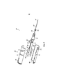
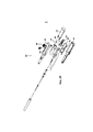
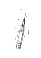
На фиг. 1А схематично показана операция имплантации интраокулярного шунта в глазное яблоко с использованием устройства введения согласно изобретению;In FIG. 1A schematically shows an operation for implanting an intraocular shunt into an eyeball using an administration device according to the invention;
на фиг. 1В - устройство введения согласно изобретению, вид в перспективе;in FIG. 1B is an introduction device according to the invention, a perspective view;
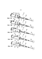
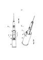
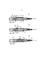
на фиг. 2 - то же, что и на фиг. 1В, но в разобранном состоянии, вид в перспективе;in FIG. 2 is the same as in FIG. 1B, but in disassembled condition, perspective view;
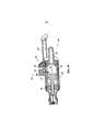
на фиг. 3 показан узел привода в разобранном состоянии устройства, показанного на фиг. 1В, вид в перспективе;in FIG. 3 shows the disassembled drive assembly of the device shown in FIG. 1B is a perspective view;
на фиг. 4А, 4В - компонент привода, показанного на фиг. 3, виды в перспективе;in FIG. 4A, 4B is a component of the drive shown in FIG. 3, perspective views;
на фиг. 5А, 5В - привод плунжера узла привода, показанного на фиг. 3, виды в перспективе;in FIG. 5A, 5B show the plunger drive of the drive assembly shown in FIG. 3, perspective views;
на фиг. 6А, 6В - привод иглы узла привода, показанного на фиг. 3, виды в перспективе;in FIG. 6A, 6B show the needle drive of the drive assembly shown in FIG. 3, perspective views;
на фиг. 7 - узел крепления иглы узла привода, показанного на фиг. 3, вид в перспективе;in FIG. 7 shows a needle attachment assembly of the drive assembly shown in FIG. 3 is a perspective view;
на фиг. 8А, 8В - поворотный регулировочный элемент узла привода, показанного на фиг. 3, виды в перспективе;in FIG. 8A, 8B is a rotary adjustment element of the drive assembly shown in FIG. 3, perspective views;
на фиг. 9А - узел крепления втулки узла привода, показанного на фиг. 3, имеющий соединенный с ним прямой игольчатый элемент, вид в перспективе;in FIG. 9A is a hub mounting assembly of the drive assembly shown in FIG. 3, having a straight needle element connected to it, a perspective view;
на фиг. 9В - узел крепления втулки узла привода, показанного на фиг. 3, имеющий соединенный с ним изогнутый игольчатый элемент, вид в перспективе;in FIG. 9B is a hub mount assembly of the drive assembly shown in FIG. 3, having a curved needle element connected to it, a perspective view;
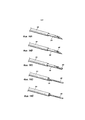
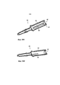
на фиг. 10 - наконечник для использования с устройством введения, вид в перспективе;in FIG. 10 — tip for use with an insertion device, perspective view;
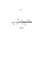
на фиг. 11 схематично показана наружная поверхность компонента привода, поясняющая контуры паза;in FIG. 11 schematically shows the outer surface of a drive component explaining the groove contours;
на фиг. 12А, 12В - скользящий элемент устройства, показанного на фиг. 1В, виды в перспективе;in FIG. 12A, 12B is a sliding element of the device shown in FIG. 1B, perspective views;
на фиг. 13А, 13В - корпус устройства введения, показанного на фиг. 1В, виды в перспективе;in FIG. 13A, 13B show the housing of the introduction device shown in FIG. 1B, perspective views;
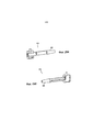
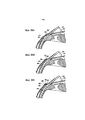
на фиг. 14А-14Е - устройство введения, показанное на фиг. 1В, на различных этапах перемещения приводного узла, виды сбоку в разрезе;in FIG. 14A-14E are the introduction device shown in FIG. 1B, at various stages of movement of the drive unit, sectional side views;
на фиг. 15А-15Е - узел привода, показанный на фиг. 3, на различных этапах его перемещения, виды в перспективе;in FIG. 15A-15E are the drive assembly shown in FIG. 3, at various stages of its movement, perspective views;
на фиг. 16А-16Е - этапы перемещения иглы и втулки при перемещении узла, показанного на фиг. 15А-15Е, виды в перспективе;in FIG. 16A-16E show the steps of moving the needle and the sleeve when moving the assembly shown in FIG. 15A-15E, perspective views;
на фиг. 17 - поворотный регулировочный механизм устройства введения, показанного на фиг. 1В, вид сбоку в разрезе;in FIG. 17 is a rotary adjustment mechanism of the insertion device shown in FIG. 1B is a sectional side view;
на фиг. 18 - поворотный регулировочный механизм, показанный на фиг. 17, вид сверху;in FIG. 18 is a rotary adjustment mechanism shown in FIG. 17 is a plan view;
на фиг. 19А-19С - положения иглы при угловой регулировке под действием перемещения поворотного регулировочного механизма;in FIG. 19A-19C - the position of the needle during angular adjustment under the action of moving the rotary adjusting mechanism;
на фиг. 20 - устройство введения согласно другому варианту осуществления изобретения, вид в перспективе;in FIG. 20 is an perspective view of an introduction device according to another embodiment of the invention;
на фиг. 21 - узел привода устройства, показанного на фиг. 20, в разобранном состоянии, вид в перспективе;in FIG. 21 is a drive assembly of the device shown in FIG. 20, in disassembled condition, perspective view;
на фиг. 22 - фрагмент устройства введения, показанного на фиг. 20, вид сбоку в разрезе;in FIG. 22 is a fragment of the introduction device shown in FIG. 20 is a sectional side view;
на фиг. 23А, 23В - привод иглы устройства введения, показанного на фиг. 20, виды в перспективе;in FIG. 23A, 23B is a needle drive of the insertion device shown in FIG. 20, perspective views;
на фиг. 24 - устройство введения, согласно другому варианту осуществления изобретения, вид в перспективе;in FIG. 24 is a perspective view of an introduction device according to another embodiment of the invention;
на фиг. 25 - устройство введения, показанное на фиг. 24, в разобранном состоянии, вид в перспективе;in FIG. 25 is an introduction device shown in FIG. 24, in disassembled condition, perspective view;
на фиг. 26А, 26В - устройство введения, показанное на фиг. 24, на различных этапах перемещения узла привода, виды сбоку в разрезе;in FIG. 26A, 26B is an introduction device shown in FIG. 24, at various stages of movement of the drive assembly, sectional side views;
на фиг. 27А, 27В - игла, втулка и плунжер устройства введения, показанного на фиг. 24, на различных этапах перемещения соответствующих элементов, показанных на фиг. 26А, 26В, виды в разрезе;in FIG. 27A, 27B show the needle, sleeve, and plunger of the insertion device shown in FIG. 24, at various stages of the movement of the respective elements shown in FIG. 26A, 26B, sectional views;
на фиг. 28А-28В - первая и вторая половины корпуса устройства введения, показанного на фиг. 24, виды в перспективе;in FIG. 28A-28B show the first and second halves of the housing of the introduction device shown in FIG. 24, perspective views;
на фиг. 29 - устройство введения, показанное на фиг. 24, вид в перспективе в разрезе;in FIG. 29 is an introduction device shown in FIG. 24 is a sectional perspective view;
на фиг. 30А, 30В - устройство введения согласно еще одному варианту осуществления изобретения на различных этапах перемещения его рукоятки, виды сверху и в перспективе;in FIG. 30A, 30B is an introduction device according to another embodiment of the invention at various stages of moving its handle, top and perspective views;
на фиг. 31 - устройство введения с узлом привода по другому варианту его выполнения, вид в перспективе;in FIG. 31 is an introduction device with a drive unit according to another embodiment, a perspective view;
на фиг. 32А-32С - приводимые в действие кнопкой пружинные узлы привода для устройства введения, виды сбоку в разрезе;in FIG. 32A-32C are button-actuated spring drive units for the introduction device, sectional side views;
на фиг. 33 - устройство фиксации имплантата, размещенное в просвете иглы устройства введения, вид сбоку в разрезе;in FIG. 33 is an implant fixation device placed in the lumen of a needle of an insertion device, a sectional side view;
на фиг. 34А-34С схематично показаны этапы операции по имплантации интраокулярного шунта;in FIG. 34A-34C schematically show the steps of an intraocular shunt implantation operation;
на фиг. 35А-35С - этапы другой операции по имплантации интраокулярного шунта;in FIG. 35A-35C - stages of another operation for implantation of an intraocular shunt;
на фиг. 36А-36С - этапы еще одной операции по имплантации интраокулярного шунта;in FIG. 36A-36C - the stages of another operation for implantation of an intraocular shunt;
на фиг. 37-39 - этапы подготовительной операции для имплантации интраокулярного шунта.in FIG. 37-39 - stages of the preparatory operation for implantation of an intraocular shunt.
Осуществление изобретенияThe implementation of the invention
В дальнейшем описании многие конкретные детали изложены для того, чтобы обеспечить полное понимание изобретения. Следует понимать, что изобретение может быть осуществлено на практике без некоторых таких конкретных деталей. В других случаях хорошо известные конструкции и технологии подробно не показаны для того, чтобы не затруднять понимание изобретения.In the following description, many specific details are set forth in order to provide a thorough understanding of the invention. It should be understood that the invention can be practiced without some such specific details. In other cases, well-known structures and technologies are not shown in detail in order not to obscure the understanding of the invention.
Несмотря на то, что в описании представлены конкретные детали различных вариантов осуществления изобретения, следует понимать, что такое описание носит лишь иллюстративный характер и не должно быть истолковано как ограничение. Кроме того, предполагается, что, хотя конкретные варианты осуществления изобретения могут быть описаны или представлены в контексте операций «ab interno», такие варианты осуществления изобретения могут быть использованы в операциях «ab externo». Более того, различные области применения таких вариантов осуществления изобретения и последующие изменения и дополнения, которые могут быть сделаны специалистам в данной области, также охватываются общими концепциями, представленными в настоящем описании.Although the description provides specific details of various embodiments of the invention, it should be understood that such a description is merely illustrative and should not be construed as limiting. It is further contemplated that although specific embodiments of the invention may be described or presented in the context of ab interno operations, such embodiments of the invention may be used in ab externo operations. Moreover, various fields of application of such embodiments of the invention and subsequent changes and additions that can be made to specialists in this field are also covered by the general concepts presented in the present description.
Глаукома представляет собой заболевание, при котором повреждается зрительный нерв, что приводит к прогрессирующей необратимой потере зрения. Как правило, это связано с повышенным давлением жидкости (т.е. внутриглазной жидкости) в глазном яблоке. При отсутствии лечения глаукома приводит к необратимому повреждению зрительного нерва и, как следствие, к потере поля зрения, которая может прогрессировать до слепоты. Такое нарушенное поле зрения после потери не может быть восстановлено.Glaucoma is a disease in which the optic nerve is damaged, which leads to progressive irreversible loss of vision. Typically, this is due to increased fluid pressure (i.e., intraocular fluid) in the eyeball. If untreated, glaucoma leads to irreversible damage to the optic nerve and, as a result, to a loss of the field of view, which can progress to blindness. Such a disturbed field of view after loss cannot be restored.
При глаукоме давление внутриглазной жидкости в глазном яблоке (передней камере) увеличивается, что может привести к повреждению сосудистой системы в заднем отделе глазного яблока и, в частности, зрительного нерва. Лечение глаукомы и других заболеваний, которые приводят к повышенному давлению в передней камере, предполагает снижение этого давления до нормального уровня.With glaucoma, the pressure of the intraocular fluid in the eyeball (anterior chamber) increases, which can lead to damage to the vascular system in the posterior part of the eyeball and, in particular, the optic nerve. The treatment of glaucoma and other diseases that lead to increased pressure in the anterior chamber, involves reducing this pressure to a normal level.
Как правило, для лечения глаукомы осуществляют хирургическое вмешательство для отвода избыточной жидкости. Операция включает в себя размещение шунта в глазном яблоке для уменьшения внутриглазного давления посредством создания пути для выпуска внутриглазной жидкости из передней камеры глазного яблока. Обычно шунт располагают в глазном яблоке так, что он создает дренажный канал между передней камерой глазного яблока и областью более низкого давления. Различные структуры и/или области глаза, имеющие более низкое давление для дренажа внутриглазной жидкости включают в себя канал Шлемма, субконъюнктивальное пространство, эписклеральные вены, супрахориоидальное пространство, или субарахноидальное пространство. Способы имплантации интраокулярных шунтов известны. Шунты могут быть имплантированы с использованием доступа «ab externo» (введение через конъюнктиву и внутрь через склеру) или доступа «ab interno» (введение через роговицу, через переднюю камеру, через трабекулярную сеть и склеру).As a rule, for the treatment of glaucoma, surgery is performed to drain excess fluid. The operation involves placing a shunt in the eyeball to reduce intraocular pressure by creating a pathway for releasing intraocular fluid from the anterior chamber of the eyeball. Typically, a shunt is placed in the eyeball so that it creates a drainage channel between the anterior chamber of the eyeball and the lower pressure area. Various structures and / or areas of the eye having lower pressure for drainage of the intraocular fluid include the Schlemm canal, subconjunctival space, episcleral veins, suprachoroidal space, or subarachnoid space. Methods for implanting intraocular shunts are known. Shunts can be implanted using the ab externo access (insertion through the conjunctiva and inward through the sclera) or the ab interno access (insertion through the cornea, through the anterior chamber, through the trabecular network and sclera).
Далее описаны варианты осуществления изобретения со ссылками на чертежи для пояснения изобретения, однако варианты его осуществления могут быть различными. Дополнительно к описанным различным конструктивным особенностям и вариантам выполнения различных элементов могут быть представлены различные способы их функционирования. Такие способы проиллюстрированы несколькими из представленных фигур.Embodiments of the invention are described below with reference to the drawings to explain the invention, however, embodiments thereof may be different. In addition to the various design features and embodiments of various elements described, various methods of their functioning may be presented. Such methods are illustrated by several of the figures shown.
Изобретение относится к нескольким изобретениям и вариантам выполнения устройства введения интраокулярного шунта, используемого в хирургии глаза. Некоторые варианты выполнения устройства могут быть предназначены для использования с имплантатом AqueSys XEN™. Устройство введения может быть изготовлено из отлитого под давлением пластика для снижения стоимости устройства одноразового использования. Шунт может быть предварительно загружен в устройство введения.The invention relates to several inventions and embodiments of the device for the introduction of an intraocular shunt used in eye surgery. Some embodiments of the device may be intended for use with an AqueSys XEN ™ implant. The insertion device may be made of injection molded plastic to reduce the cost of the disposable device. The shunt may be preloaded into the insertion device.
Конструкции устройства введения для работы одной рукойOne-handed insertion device designs
Устройство введения может выполнено для работы одной рукой, чтобы позволить хирургу другой рукой держать фиксирующее приспособление, удерживающее глазное яблоко, например, крючок. Это может улучшить хирургический контроль и точность размещения, а также облегчает проведение операции. На фиг. 1А показана операция лечения глаза 12, при которой используют крючок 14 для удерживания глаза 12 и устройство 100 для введения интраокулярного шунта в глазное яблоко.The insertion device may be designed to work with one hand to allow the surgeon to hold the fixing device holding the eyeball with the other hand, for example, a hook. This can improve surgical control and placement accuracy, and also makes surgery easier. In FIG. 1A shows an
На фиг. 1B-19С показаны дополнительные элементы устройства 100 введения, показанного на фиг. 1А. Устройство 100 введения может быть приведено в действие одной рукой, облегчая использование этого устройства хирургом. Устройство 100 может содержать корпус 102, иглу 104, и скользящий элемент 106. Как показано на фиг. 1В, устройство 100 может быть выполнено так, что скользящий элемент 106 соединяется с корпусом 102 с возможностью скольжения вдоль удлиненного паза 110, выполненного в этом корпусе 102. Скользящий элемент 106 может быть выполнен с возможностью перемещения по выбору хирурга для активации перемещения элементов узла 104 иглы.In FIG. 1B-19C show additional elements of the
Например, когда скользящий элемент 106 перемещается от центра корпуса вдоль паза 110 (т.е. к узлу 104 иглы), он может обеспечивать продвижение шунта (не показан) внутри узла 104 иглы, а в некоторых вариантах выполнения и к освобождению от этого узла 104 и иглы. В некоторых вариантах перемещение скользящего элемента 106 может приводить к перемещению элементов узла 104 иглы. Скользящее перемещение скользящего элемента 106 может быть преобразовано в поворотное перемещение, которое может быть преобразовано в перемещение вдоль продольной оси устройства 100 введения. Одним из уникальных преимуществ этого нового и сложного механизма преобразования перемещения является то, что он позволяет обеспечить точное, рассчитанное перемещение элементов устройства внутри компактного узла.For example, when the sliding
Как показано на фиг. 2, узел 104 иглы может содержать иглу 120, плунжер 122 и втулку 124. Игла 120 может представлять собой иголку калибром 25 или 27. Плунжер 122 может быть выполнен с возможностью скольжения внутри просвета иглы 120 вдоль продольной оси 178 устройства 100 введения. Кроме того, игла 120 может быть выполнена с возможностью скольжения в полости втулки 124 вдоль указанной продольной оси 178. Как игла 120, так и плунжер 122 могут быть соединены с соответствующими компонентами узла привода 130, расположенного внутри корпуса 102. В собранном состоянии устройство 100 введения может быть выполнено так, что игла 120, плунжер 122 и втулка 124 располагаются вдоль одной оси или коаксиально с продольной осью 178. Некоторые узлы привода для приведения в действие плунжера и извлечения иглы в устройстве введения описаны в заявках US 13/336803, US 12/946645, US 12/620564, US 12/946653, US 12/946565, и US 11/771805.As shown in FIG. 2, the
Как показано на фиг. 2 и 3, игла 120, плунжер 122 и втулка 124 могут быть функционально соединены с узлом 130 привода и/или корпусом 102. Например, игла 120 может быть соединена с узлом 140 крепления иглы. Узел 140 крепления иглы, показанный на фиг. 2, 3 и 7, может быть неподвижно соединен с проксимальным концом иглы 120 так, что поворотное и продольное перемещение иглы 120 относительно узла 140 крепления иглы ограничивается или предотвращается. При сборке устройства 100 узел 140 крепления иглы может быть размещен в дистальном конце корпуса 102. Кроме того, как показано на фиг. 3 и описано ниже, узел 140 крепления иглы может быть соединен с приводом 164 иглы (в показанном варианте выполнения - с использованием поворотного регулировочного элемента 370) узла 130 привода.As shown in FIG. 2 and 3, the
Как показано на фиг. 3, плунжер 122 может быть соединен с узлом 142 его крепления. Узел крепления 142 плунжера, показанный на фиг. 3, 5А и 5В, может быть неподвижно соединен с проксимальным концом или средней частью плунжера 122 для ограничения или предотвращения его вращательного и продольного перемещения относительно этого узла 142 крепления. Как показано на фиг. 3 и описано далее, узел крепления 142 плунжера может быть соединен с приводом 162 плунжера узла 130 привода.As shown in FIG. 3, the
Кроме того, втулка 124 может быть соединена с узлом 144 ее крепления. Этот узел 144, показанный на фиг. 2, 3 и 9, может быть соединен с проксимальным концом втулки 124 так, чтобы предотвратить вращательное и продольное перемещение этой втулки 124 относительно узла 144 ее крепления. Узел 144 крепления втулки может быть соединен с частью 148 корпуса 102, как будет описано далее.In addition, the
Игла 120, плунжер 122 и втулка 124 могут быть функционально связаны с узлом 130 привода и/или корпусом 102. Такое соединение может осуществляться посредством узла 140 крепления иглы, узла 142 крепления плунжера и узла 144 крепления втулки. Однако узел 140 крепления иглы, узел 142 крепления плунжера и узел 144 крепления втулки могут быть соединены с одним или несколькими приводными элементами, которые соединяют узел 130 привода с корпусом 102.The
Согласно некоторым вариантам выполнения узел 130 привода может быть соединен с иглой 120 и плунжером 122 для обеспечения их перемещения относительно корпуса 102 вдоль продольной оси 178. Например, узел 130 привода может быть выполнен с возможностью поворота или скольжения внутри корпуса 102. Узел 130 привода может передавать продольное или осевое усилие вдоль продольной оси 178 на иглу 120 и/или плунжер 122 по отдельности или одновременно для обеспечения их перемещения относительно корпуса 102 вдоль продольной оси 178.In some embodiments, the
Перемещение скользящего элемента 106 может вызывать перемещение узла 130 привода и посредством этого обеспечивать перемещение элементов узла 130 привода относительно корпуса 102. Согласно изобретению скользящий элемент 106 может быть выполнен с возможностью перемещения в продольном направлении или с возможностью скольжения вдоль продольной оси 178 относительно корпуса 102 для приведения в движение или обеспечения линейного перемещения иглы 120 и плунжера 122.Moving the sliding
Как показано на фиг. 2-6В, узел 130 привода может содержать компонент 160 привода, привод 162 плунжера и привод 164 иглы. Продольное или линейное перемещение скользящего элемента 106 вдоль продольной оси 178 может быть преобразовано так, что оно обеспечивает поворот компонента 160 привода узла 130 привода, при этом указанный поворот может быть преобразован для обеспечения продольного или линейного перемещения иглы 120 и плунжера 122 вдоль продольной оси 178 относительно корпуса 102. Перемещение элементов вдоль продольной оси 178 может быть параллельным относительно продольной оси 178. На фиг. 14А-16Е показано взаимодействие между элементами узла 104 иглы и узла 130 привода в соответствие с изобретением.As shown in FIG. 2-6B, the
На фиг. 2 и 9А-9В показаны конструкции, посредством которых узел 144 крепления втулки может быть соединен с корпусом 102. Например, узел 144 крепления втулки может включать в себя выступ или паз 146, которые могут совпадать с соответствующим выступом или пазом 148 на одной или нескольких частях корпуса 102. Когда корпус 102 собран, выступ 148 может быть размещен в пазу 146, обеспечивая фиксацию узла 144 крепления втулки в корпусе 102. В некоторых вариантах выполнения, когда устройство 100 собрано, игла 120 и плунжер 122 подвижны относительно друг друга, корпуса 102 и втулки 124.In FIG. 2 and 9A-9B show structures by which the
Как показано на фиг. 9А, узел 144 крепления втулки соединен с прямой втулкой 124. На фиг. 9В показана втулка 124, имеющая небольшую кривизну или изгиб 290. Изгиб 290 может располагаться около узла 144 крепления втулки и образовывать относительно продольной оси 178 угол 292 отклонения в диапазоне от 5° до 30°, от 8° до 15°, от 9° до 13° или 10°.As shown in FIG. 9A, the
Изгиб втулки 124 может улучшить доступ к участкам глазного яблока, например, из положения, в котором это устройство располагается над скуловой костью.The bending of the
Кроме того, дистальный конец 294 втулки 124 может быть по существу прямым, а проксимальный конец 296 втулки 124 может быть искривленным или изогнутым. Проксимальный конец 296 может составлять от четверти до половины всей длины втулки 124. В некоторых случаях длина проксимального конца 296 может составлять треть всей длины втулки 124. Соответственно, дистальный конец 294 может составлять от половины до трех четвертей всей длины втулки 124, а в некоторых случаях - около двух третьих всей длины втулки 124. Кроме того, предпочтительно дистальный конец 294 может иметь достаточную длину, чтобы вся втулка 124, вводимая в глазное яблоко, была по существу прямой.In addition, the
В то время как втулка 124 может иметь жесткую конструкцию, выдерживающую стандартные напряжения изгиба во время выполнения операций, раскрытых в настоящем описании, игла 120 может быть выполнена из гибкого стержня, способного отклоняться во время проксимального выведения иглы 120 во втулку 124.While the
Таким образом, проксимальная часть иглы 120, проходящая вдоль изгиба 290 втулки 124, может быть выведена во втулку 124 ближе к узлу 144 крепления втулки или вблизи него. После этого перемещения, несмотря на то, что проксимальная часть иглы 120 изогнута, она может изгибаться и выпрямляться, когда иглу 120 вытягивают в проксимальном направлении в прямую часть втулки 124 или других компонентов внутри устройства введения. Кроме того, участки иглы 120, расположенные в дистальном конце втулки 124 (находящейся в прямой конфигурации) могут сгибаться или изгибаться, когда игла 120 отводится в направлении проксимального конца корпуса назад через изгиб 290 этой втулки 124.Thus, the proximal part of the
При использовании дугообразной или изогнутой втулки 124 в сочетании с гибкой или подходящей по форме иглой 120 может быть улучшен доступ к областям глазного яблока.By using an arched or
Некоторые варианты выполнения могут повторять конструкции трубки и способов применения, раскрытые в заявке US 2012/0123434.Some embodiments may repeat the tube designs and methods of application disclosed in US 2012/0123434.
Используемый в настоящем описании термин «паз» или «пазы» обозначает элемент конструкции, который может быть реализован в различных вариантах. Понятие «паз» или «пазы» подразумевает и (и наоборот) другие элементы конструкции, направляющие перемещение или принимающие соответствующий выступ, такие как направляющая, пространство между зубьями, углубление, вырез, выемка, отверстие, канал, проход, паз, или прорезь, и т.д., проходящие по меньшей мере частично в детали или через нее. Кроме того, понятие «выступ» или «выступы» подразумевает и (и наоборот) другие элементы конструкции, такие как гребень, выпуклость, зуб, бугор и т.д. Элементы конструкции, такие как пазы и выступы могут быть взаимозаменяемыми. Несмотря на то, что в описании указано лишь несколько примеров конструкций выступ/паз, возможны различные комбинации таких элементов конструкции.Used in the present description, the term "groove" or "grooves" refers to a structural element that can be implemented in various ways. The term "groove" or "grooves" means and (and vice versa) other structural elements that guide the movement or take the corresponding protrusion, such as the guide, the space between the teeth, the recess, cutout, recess, hole, channel, passage, groove, or slot, etc., passing at least partially in or through the part. In addition, the term “protrusion” or “protrusions” implies (and vice versa) other structural elements, such as a crest, bulge, tooth, tubercle, etc. Structural elements such as grooves and protrusions may be interchangeable. Although only a few examples of protrusion / groove structures are indicated in the description, various combinations of such structural elements are possible.
На фиг. 3 показан узел 130 привода в разобранном состоянии. Компонент 160 привода показан в виде конструкции из двух частей, которая в собранном состоянии, по меньшей мере частично, вмещает одну или несколько частей других элементов узла 130 привода (показано на фиг. 2). Две части компонента 160 привода могут быть соединены между собой посредством ряда взаимодействующих выступов и выемок, облегчая тем самым механическое и/или клеевое соединение частей для формирования составного компонента.In FIG. 3 shows a disassembled
Компонент 160 привода может содержать один или несколько пазов и/или один или несколько выступов для облегчения зацепления и перемещения других элементов узла 130 привода. Компонент 160 привода может содержать ряд пазов, входящих в зацепление с соответствующими выступами или пазами на других элементах узла 130 привода для упрощения преобразования одного вида перемещения в другое. Действие и перемещение компонентов узла 130 привода в проиллюстрированном варианте осуществления изобретения представляют собой лишь один из множества вариантов осуществления изобретения.The
В варианте, показанном на фиг. 3, скользящий элемент 106, привод 162 плунжера и привод 164 иглы могут содержать радиальный выступ, входящий в паз компонента 160 привода для передачи осевого или продольного усилия между элементами и приводами для приведения в действие устройства введения 100. Компонент 160 привода может содержать один или несколько пазов канавок для соединения со скользящим элементом 106, приводом 162 плунжера, и приводом 164 иглы.In the embodiment shown in FIG. 3, the sliding
На фиг. 3-4В показан вариант выполнения компонента 160 привода. Как показано на фиг. 4А-4В, компонент 160 привода может содержать паз 170 для зацепления с соответствующим выступом скользящего элемента 106. Кроме того, компонент 160 привода также может содержать первую и вторую ведущие пазы 172, 174 для соединения с возможностью скольжения с соответствующими выступами привода 162 плунжера и привода 164 иглы. Скользящий элемент 106 может содержать выступ 180 (фиг. 12В), привод 162 плунжера может включать в себя выступ 182 (фиг. 5А-5В), а привод иглы 164 может содержать выступ 184 (фиг. 6А-6В). Такое расположение пазов и выступов может упростить передачу перемещения скользящего элемента 106 к одному из соответствующих элементов: игле 120 и плунжеру 122.In FIG. 3-4B shows an embodiment of a
В некоторых варианты выполнения выступы и пазы меняться местами, в результате чего один или несколько таких элементов, как скользящий элемент 106, привод 162 плунжера или привод 164 иглы содержат паз, в котором может размещаться выступ компонента 160 привода. В таких вариантах выполнения к компоненту 160 привода может быть присоединен или прикреплен внутренний выступ с возможностью скольжения в пазах компонента 160 привода, что обеспечивает поворот компонента 160 привода и продольное перемещение привода 162 плунжера и привода 164 иглы. В других вариантах выполнения компонент 160 привода может содержать выступающий в радиальном направлении гребень, вдоль которого может скользить привод 162 плунжера или привод 164 иглы (например, посредством зацепления гребня и паза, позволяя гребню компонента 160 привода скользить в пазу привода 162 плунжера или привода 164 иглы). Такие выступы на компоненте 160 привода могут отходить в радиальном направлении внутрь (к продольной оси 178) или радиально наружу (от продольной оси 178) от поверхности этого компонента 160. Возможны различные конфигурации взаимодействующих конструкций скользящего элемента 106, привода 162 плунжера, привода 164 иглы и компонента 160 привода устройства 100 введения.In some embodiments, the protrusions and grooves are interchanged, resulting in one or more elements such as a sliding
Несмотря на то, что компонент 160 привода может поворачиваться относительно корпуса 102, поворотное (относительно продольной оси 178) относительно корпуса 102 скользящего элемента 106, привода 162 плунжера и привода 164 иглы может быть ограничен. Поворот скользящего элемента 106, привода 162 плунжера, и/или привода 164 иглы относительно корпуса 102 может быть ограничен за счет непосредственного или опосредованного зацепления с корпусом 102. Скользящий элемент 106 может скользить вдоль паза 110 корпуса 102 и входить в зацепление с ним посредством выступа 180. Это зацепление может обеспечить продольное перемещение скользящего элемента 106 при ограничении его поворота относительно корпуса 102. Привод 162 плунжера и/или привод 164 иглы (которые могут быть расположены радиально внутри компонента 160 привода) может содержать одну или несколько направляющих поверхностей или конструкций определенной формы, которые входят в зацепление с соответствующей внутренней направляющей поверхностью или конструкцией корпуса 102, ограничивая поворот привода 162 плунжера и/или привода 164 иглы относительно корпуса 102.Although the
Привод 162 плунжера и привод 164 иглы могут содержать продолговатые корпуса, имеющие часть с по существу прямоугольной формой поперечного сечения. Как показано на фиг. 5А-6В, привод 162 плунжера и привод 164 иглы могут иметь соответствующие профили в поперечном сечении, которые позволяют их скомпоновать вместе, обеспечивая возможность скольжения привода 162 плунжера и привода 164 иглы вдоль продольной оси 178 относительно друг друга при ограничении поворота привода 162 плунжера относительно привода 164 иглы вокруг продольной оси 178.The
Как показано на фиг. 5А-5В, привод плунжера может содержать продолговатое основание 190. Продолговатое основание 190 может иметь по существу прямоугольный профиль в поперечном сечении. Продолговатое основание 190 может быть соединено с направляющей 192. Привод 162 плунжера может содержать направляющую 192, соединенную с проксимальным концом 194 продолговатого основания. Направляющая 192 может содержать выступ 182. Кроме того, направляющая 192 может содержать наружную или внешнюю направляющую поверхность 196, выполненную с возможностью прилегания или соответствия с внутренней или находящейся внутри направляющей поверхностью компонента 160 привода. Например, это может быть наружная поверхность 196, которая показана на фиг. 3. Направляющая поверхность 196 может быть выполнена с возможностью прилегания к соответствующей направляющей поверхности 198 компонента 160 привода.As shown in FIG. 5A-5B, the plunger drive may comprise an
Как показано на фиг. 6А-6В привод иглы может содержать продолговатое основание 200, имеющее проксимальный конец 202 и дистальный конец 204, при этом привод 164 иглы может содержать направляющую 210, соединенную с проксимальным концом 202. Направляющая 210 может содержать выступ 184. Направляющая 210 может содержать по меньшей мере одну соединительную конструкцию или направляющую поверхность 212. Как показано, соединительная конструкция 212 может содержать полость, имеющую по существу прямоугольный профиль в поперечном сечении. Профиль в поперечном сечении соединительной конструкции 212 может соответствовать наружному профилю в поперечном сечении продолговатого основания 190 привода плунжера 162.As shown in FIG. 6A-6B, the needle drive may comprise an
Как показано на фиг. 3, при сборке продолговатое основание 190 привода 162 плунжера может входить со скольжением в полость соединительной конструкции 212 привода 164 иглы. Скользящее зацепление между продолговатым основанием 190 и соединительной конструкцией 212 может обеспечить продольное перемещение привода 162 плунжера относительно привода 164 иглы, при этом плотное прилегание прямоугольных профилей в поперечном сечении продолговатого основания 190 и соединительной конструкции 212 по существу ограничивает поворот привода 162 плунжера относительно привода 164 иглы.As shown in FIG. 3, during assembly, the
Кроме того, поворот привода 162 плунжера и привода 164 иглы относительно корпуса 102 может быть ограничен посредством зацепления профилей поперечного сечения привода 162 плунжера, либо привода 164 иглы, или их обоих, с/между соответствующей соединительной конструкцией или направляющей поверхностью внутри полости 228 корпуса 102. Согласно изобретению поворот привода 162 плунжера и привода 164 иглы относительно корпуса 102 может быть ограничен.In addition, the rotation of the
В некоторых вариантах выполнения для ограничения поворота привода 162 плунжера и привода 164 иглы относительно корпуса 102, выступ 182 указанного привода 162 и выступ 184 указанного привода 164 могут проходить через компонент 160 привода и входить в зацепление с соответствующим пазом 220 корпуса 102 (фиг. 13В). Поскольку выступы 182, 184 проходят через компонент 160 привода в пазу 220 корпуса 102, они могут входить в зацепление с этим корпусом 102 для ограничения или регулировки поворота привода 162 плунжера и привода 164 иглы относительно этого корпуса 102. Выступы 182, 184 могут перемещаться по заданной траектории, например, прямолинейной или криволинейной, определенной пазом 220, выполненным в корпусе 102. В представленных вариантах выполнения изобретения паз 220 корпуса 102 может использоваться как для привода 162 плунжера, так и для привода 164 иглы. Кроме того, прорезь 220 может определить путь, который является, по существу, параллельным продольной оси 178 корпуса 102.In some embodiments, to limit the rotation of the
Скользящий элемент 106 может быть выполнена так, что его выступ 180 проходит через корпус 102 в паз 170 компонента 160 привода.The sliding
Как показано на фиг. 4А-4В, паз 170 для скользящего элемента может проходить по винтовой траектории вокруг компонента 160 привода. На виде сверху винтовая траектория паза 170 для скользящей детали может быть по существу прямолинейной, как показано на фиг. 11 (например, паз 170 для скользящего элемента может иметь по существу постоянный угол наклона). Выступ 180 скользящего элемента 106 может перемещаться или проходить внутри паза 170 из первого положения во второе, третье, четвертое и пятое положения. Поскольку скользящий элемент перемещается в продольном направлении вдоль корпуса 102, указанный выступ 180 перемещается между положениями, показанными на фиг. 11. Такое продольное перемещение выступа 180 вдоль продольной оси 178 может привести к повороту перемещению компонента 160 привода. Поворот компонента 160 привода может привести к продольному перемещению привода 162 плунжера и/или привода 164 иглы вдоль продольной оси 178.As shown in FIG. 4A-4B, the
Как показано на фиг. 4А-4В, первый и второй управляющие пазы 172, 174 компонента 160 привода могут быть приспособлены для зацепления с выступами 182, 184. В представленном варианте выполнения первый и второй ведущие пазы 172, 174 могут содержать прямолинейный или прямой участок, через который может проходить выступ, не обеспечивая продольное перемещение соответствующей приводной детали, и наклонный участок, через который может проходить выступ, обеспечивающий продольное перемещение соответствующей приводной детали. Например, первый управляющий паз 172 может содержать прямой участок 230 и наклонный участок 232. Выступ 182 привода 162 плунжера может перемещаться или проходить вдоль различных положений внутри первого управляющего паза 172. Это перемещение может осуществляться посредством передвижения скользящего элемента 106.As shown in FIG. 4A-4B, the first and
На фиг. 11 показаны в развертке траектории первого и второго управляющих пазов 172, 174 и паза 170 для скользящего элемента компонента 160 привода. Выступ 182 может перемещаться из первого положения во второе, третье, четвертое и пятое положения в пределах первого управляющего паза 172. Поскольку первый выступ 182 перемещается из первого положения во второе в пределах наклонного участка первого управляющего паза, такое перемещение обеспечивает перемещение привода плунжера относительно компонента 160 привода вдоль продольной оси 178. Перемещение привода 162 плунжера из первого положения во второе и третье положения показано на фиг. 14А-14С. Когда выступ 182 перемещается по наклонному участку 232 первого паза 172, привод 162 плунжера может выдвигаться в дистальном направлении вдоль продольной оси 178, пока выступ 182 не войдет в прямой участок 230 первого управляющего паза 172. После этого, в третьем, четвертом и пятом положениях выступ 182 будет сохранять по существу постоянное продольное положение вдоль продольной оси 178 относительно компонента 160 привода. Соответственно, привод 162 плунжера не меняет своего продольного положения вдоль продольной оси 178, т.к. компонент привода продолжает поворачиваться, в результате чего выступ 182 перемещается из третьего положения в пятое положение.In FIG. 11 shows in a sweep the paths of the first and
Аналогично выступу 182, расположенному внутри первого управляющего паза 172, выступ 184 может проходить внутри второго управляющего паза 174 и перемещаться вдоль траектории, определенной вторым управляющим пазом 174. Второй управляющий паз 174 может содержать прямой участок 240 и наклонный участок 242. Выступ 184 привода 164 иглы может перемещаться из первого положения во второе, третье, четвертое и пятое положения. В первом, втором и третьем положениях выступ 184 будет по существу сохранять свое продольное положение вдоль продольной оси 178 по отношению к компоненту 160 привода. Кроме того, когда выступ 184 выходит из прямого участка 240 второго управляющего паза 174 и входит в наклонный участок 242, продольное положение привода 164 иглы вдоль продольной оси 178 начнет меняться. Таким образом, во время начального перемещения из первого положения в третье, привод иглы 164 будет сохранять свое продольное положение вдоль продольной оси 178 относительно компонента 160 привода. При этом привод 164 иглы будет проксимально отведен назад вдоль продольной оси 178 относительно компонент 160 привода из-за того, что выступ 184 перемещается через наклонный участок 242 второго управляющего паза 174.Similarly to the
Передвижение скользящего элемента 106 и возникшее в результате перемещение элементов узла 130 привода будет описано далее со ссылкой на фиг. 11 и фиг. 14А-16Е. Из положения 1 (на фиг. 11), как показано на фиг. 14А и 15А, скользящий элемент 106 может перемещаться от центра корпуса в положение 2. Перемещение из положения 1 в положение 2 приводит к вращению компонента 160 привода, что обеспечивает продольное перемещение привода 162 плунжера, как показано на фиг. 14В и 15В. Как показано на фиг. 16В, перемещение привода 162 плунжера в направлении от центра корпуса вдоль продольной оси приводит к перемещению шунта 300 так, что он сначала выходит из иглы 120.The movement of the sliding
При перемещении скользящего элемента 106 в положение 3, привод 162 плунжера продолжает перемещаться в дистальном направлении, в то время как привод 164 иглы сохраняет то же продольное положение вдоль продольной оси относительно компонента 160 привода, как показано на фиг. 14С и 15С. В результате шунт 300 выталкивается из иглы 120, как показано на фиг. 16С или далее.As the sliding
Дальнейшее дистальное перемещение скользящего элемента 106 вдоль продольной оси обеспечивает перемещение выступа 180 из положения 3 в положение 4. Такой продолжительный поворот компонента 160 привода больше не вызывает дистального продольного перемещения привода 162 плунжера вдоль продольной оси. Вместо этого продолжительный поворот компонента 160 привода приводит к продольному проксимальному перемещению привода 164 иглы назад относительно этого компонента 160 привода вдоль продольной оси. Таким образом, игла втягивается внутрь втулки 124, как показано на фиг. 14D, 15D, и 16D, или 16Е.Further distal movement of the sliding
После такого продолжительного перемещения скользящего элемента 106 в положение 5 будет происходить проксимальное втягивание привода 164 иглы относительно компонента 160 привода, в то время как привод 162 плунжера сохраняет свое продольное положение относительно компонента 160 привода. Таким образом, игла 120 может быть выведена назад во втулку 124, как показано на фиг. 16D или фиг. 16Е. Шунт 300 может быть оставлен в требуемой или целевой области, в то время как игла и втулка 124 удаляются. Несмотря на то, что игла 120 отведена проксимально назад, как показано на фиг. 16D-16E, плунжер 122 (хотя и не показан на фиг. 16А-16Е) может сохранять свое продольное положение относительно втулки 124, чтобы обеспечить проксимальную остановку и предотвратить проксимальное отведение назад шунта 300 в связи с тем, что игла 120 является проксимально отведенной назад во втулку 124.After such a continuous movement of the sliding
На фиг. 16D показано конечное положение иглы 120 относительно втулки 124, а на фиг. 16Е показан вариант выполнения, в котором игла 120 полностью отведена назад в проксимальном направлении во втулку 124. Положение иглы 120, показанное на фиг. 16D, может способствовать защите или предотвращению повреждения тканей глазного яблока или шунта во время его имплантации.In FIG. 16D shows the final position of the
Например, при отведении иглы 120 иглы во втулку 124 хирург может случайно переместить иглу относительно склеры, создавая тем самым боковое или вертикальное напряжение или усилие, которое может согнуть или подвергнуть напряжению иглу 120. Такое боковое или вертикальное усилие может возникнуть в тех случаях, когда хирург пытается расположить устройство введения над лицевыми структурами пациента. Часто, из-за того, что для одного из предпочтительных положений для имплантации в глазное яблоко требуется, чтобы хирург ориентировал и удерживал устройство введения выше скулы, при этом скула пациента и/или ориентирование может затруднить правильное позиционирование устройства введения относительно глазного яблока.For example, when the
Из-за возможного воздействия усилия хирурга в боковом или вертикальном направлений предпочтительно оставить по меньшей мере участок скоса иглы выдвинутым из дистального конца втулки 124 и вывести сразу полностью устройство введения из глазного яблока в положение, показанное на фиг. 16D. Таким образом, до тех пор, пока проксимальное выведение устройства введения (включая втулку 124) не выполняется для того, чтобы высвободить шунт 300 в глазном яблоке, участок скоса иглы 120 может оставаться выдвинутым и/или соприкасаться с тканями глазного яблока (например, склерой). В результате оставления иглы 120 выдвинутой или в зацеплении с тканями глазного яблока, зацепление иглы 120 с тканями глазного яблока может, как правило, обеспечивать устойчивость к любым боковым или вертикальных усилиям. Таким образом, устройство введения не будет предрасположено к «прыжкам» или подвергаться значительному сдвигу до проксимального выведения втулки 124 из тканей глазного яблока.Due to the possible impact of the surgeon's efforts in the lateral or vertical directions, it is preferable to leave at least a portion of the bevel of the needle extended from the distal end of the
Удерживание участка скоса выдвинутым из дистального конца втулки 124 предотвращает повреждения тканей глазного яблока, которое может произойти, если втулка внезапно перемещается в сторону или по вертикали, сохраняя при этом свое продольное положение относительно тканей глазного яблока. В таких ситуациях дальний конец втулки 124 может нанести царапины или иным образом повредить ткани глазного яблока. В некоторых ситуациях повреждение глазного яблока может включать повреждение радужной оболочки глаза, такое как иссечение радужной оболочки.Holding the bevel portion extended from the distal end of the
Из-за того, что шунт 300 может входить, по меньшей мере частично, во втулку 124 после того, как игла 120 полностью выведена в эту втулку 124, боковое или вертикальное усилие, действующее на эту втулку 124, может привести по существу к соприкосновению шунта 300 с полостью втулки 124. Такое соприкосновение может вытащить шунт 300 из тканей глазного яблока или иным образом повредить проксимальный конец или приточный конец шунта 300.Due to the fact that the
Согласно некоторым вариантам выполнения приблизительно от около четверти и до около полной продольной длины скоса иглы (при измерении вдоль продольной оси) могут быть выдвинуты из дистального конца втулки 124, как показано на фиг. 16D. В некоторых вариантах скос иглы может выступать из дистального конца втулки на расстоянии от около одной четверти продольной длины скоса до около трех четвертей продольной длины скоса. Более того, в некоторых вариантах скос может выступать из втулки 124 на около половину продольной длины скоса. Например, дистальный кончик скоса может проходить или выступать на расстоянии около 1 мм, около 2 мм, или около 3 мм или более из дистального конца втулки 124. С использованием этих принципов могут быть выполнены другие модификации и варианты осуществления изобретения.In some embodiments, from about a quarter to about the full longitudinal length of the bevel, the needles (as measured along the longitudinal axis) can be extended from the distal end of the
В качестве альтернативы варианту, показанному на фиг. 16D, игла 120 может быть полностью отведена назад во втулку 124 до проксимального отведения назад втулки 124 из глазного яблока.As an alternative to the embodiment shown in FIG. 16D, the
После удерживания иглы 120, по меньшей мере частично выдвинутой или сцепленной с тканями глазного яблока, как показано на фиг. 16D, проксимальное отведение втулки 124 и иглы 120 назад может уменьшить или исключить боковые и/или вертикальные усилия, действующие на шунт 300. Вследствие того, что для выведения устройства из глазного яблока рука хирурга перемещается в проксимальном направлении, устраняется большинство или каждое из боковых или вертикальных усилий натяжения, действующих на устройство введения.After holding the
Показанные на фиг. 11 траектории пазов относятся к одному из вариантов перемещения и приведения в действие элементов узла 130 привода, однако для различных типов перемещений этих элементов могут быть использованы и другие траектории.Shown in FIG. 11, the groove paths refer to one of the options for moving and actuating the elements of the
Например, наклонный участок пазов может иметь криволинейную траекторию, которая увеличивает или уменьшает продольное смещение этого элемента на единицу поворота при вращении компонента 160 привода. Паз 170 для скользящего элемента может быть прямым или иметь криволинейный участок для обеспечения переменного приведения в действие или увеличения/уменьшения скорости вращения на единицу продольного перемещения скользящего элемента 106.For example, the inclined groove portion may have a curved path that increases or decreases the longitudinal displacement of this element by a unit of rotation when the
Аналогично, наклонные участки первого и второго управляющих пазов 172, 174 могут иметь криволинейные участки, увеличивающие или уменьшающие продольное смещение на единицу поворота. Первый и второй управляющие пазы 172, 174 могут быть выполнены по существу криволинейными, переходящими из прямого участка в наклонный, или обеспечивающих продольное перемещение соответствующего компонента и поддерживающих продольное положение этого соответствующего компонента. Первый и второй управляющие пазы 172, 174 могут иметь либо более четко определенный переход между участками пазов, вдоль которых перемещение выступов обеспечивает перемещение вдоль оси 178, либо участками пазов, поддерживающих положение вдоль оси 178 соответствующего компонента. В качестве альтернативы, первый и второй управляющие пазы 172, 174 могут иметь траекторию, обеспечивающую постепенный, плавный или менее видимый переход от участка паза, вдоль которого перемещение выступа обеспечивает перемещение элемента вдоль оси 178, к другому участку паза, вдоль которого перемещение выступа обеспечивает удерживание этого элемента в определенном положении вдоль оси 178.Similarly, the inclined sections of the first and
Кроме того, первый и второй управляющие пазы 172, 174 и/или паз 170 для скользящего элемента (один из пазов или любая их комбинация) могут иметь множество секций или участков, образующих другой механизм, обеспечивающий приведение в действие или другую скорость вращения, или продольное перемещение вдоль продольной оси. Соответственно, специалисты в данной области могут реализовать различные варианты выполнения для создания необходимых соединений компонентов описанного выше устройства введения.In addition, the first and
Как показано на фиг. 4А-4В, компонент 160 привода может содержать две части: первую часть 252 и вторую часть 254. Конструкция из двух частей может позволить образовать два или более паза при изготовлении литьем под давлением. Таким образом, единая составной компонент 160 привода может быть изготовлен литьем под давлением с одним или несколькими пазами, проходящими частично или полностью вдоль корпуса компонента 160 привода. Это позволит пазам изменять их направление на линии разъема 256 между первой и второй частями 252, 254, так что могут быть образованы сложные направления пазов. Например, учитывая ограничения при литье под давлением, единая литая деталь не обеспечит возможность формирования участков пазов, изменяющих направление, так как компонент не будет извлекаться из пресс-формы. Таким образом, потребуется обработка после формования. В отличие от этого, некоторые варианты выполнения, представленные в настоящем описании, преодолевают эту проблему посредством изготовления компонента из двух частей, изготовленных литьем под давлением.As shown in FIG. 4A-4B, the
Как показано на фиг. 10, устройство 100 введения может содержать колпачок 310. Колпачок 310 содержит первый конец 312 и второй конец 314. Первый конец колпачка 312 может быть выполнен открытым и с возможностью зацепления с корпусом 102 для крепления этого колпачка 310 на дальнем конце корпуса 102 для закрытия и защиты втулки 124 и иглы 120.As shown in FIG. 10, the
На фиг. 12А, 12В показан скользящий элемент 106 устройства введения, показанного на фиг. 1В. На фиг. 12А показан скользящий элемент 106 на виде в перспективе сверху. Скользящий элемент 106 может иметь проксимальный конец 316 и дистальный конец 318, которые могут содержать выпуклые контуры или края, выступающие в радиальном направлении от скользящего элемента 106 для обеспечения надежного, эргономичного захвата большим или указательным пальцем хирурга во время использования.In FIG. 12A, 12B show a sliding
Проксимальный конец 316 может содержать один или несколько радиальных выступов 324, позволяющих легко входить в зацепление с пальцем хирурга для обеспечения вращательного движения или прикладывания крутящего момента к устройству введения для его поворота вокруг продольной оси 178.The
Как показано на фиг. 12А, скользящий элемент 106 может содержать один или более промежуточных пазов или выступов 326, при этом один или оба выступа 326 могут отсутствовать в скользящем элементе 106. В некоторых вариантах выполнения отказ от использования выступов 326 может обеспечить возможность пальцу хирурга находиться более глубоко и надежно между проксимальным и дистальным концами 316, 318 скользящего элемента 106. Выступы 326 могут иметь уменьшенный профиль, переменный профиль, или могут быть выполнены в виде рядов случайно или симметрично расположенных выступов, или шиповидных выступов, или шипов.As shown in FIG. 12A, the sliding
Как показано на фиг. 12В, выступ 180 может быть выполнен за одно целое со скользящим элементом 106. Однако выступ 180 может быть выполнен и в виде отдельного элемента, прикрепляемого к скользящему элементу 106.As shown in FIG. 12B, the
На фиг. 13А, 13В показан один из вариантов выполнения корпуса 102, который содержит первую часть 320 и вторую часть 322, определяющие при соединении друг с другом внутреннюю полость 228. Обычно, показанная на фиг. 2 внутренняя полость 228 может вмещать находящийся в ней узел 130 привода.In FIG. 13A, 13B show one embodiment of the
Корпус 102 может содержать паз 334, через который может проходить выступ 180 скользящего элемента 106. Таким образом, скользящий элемент 106 может быть соединен с первой частью 320 корпуса 102, а выступ 180 скользящего элемента 106 может проходить через паз 110. При прохождении через паз 110 выступ 180 может входить в зацепление с пазом 170 в компоненте 160 привода.The
Вторая часть 322 корпуса 102 может содержать паз 220, как описано выше. Паз 220 может входить в зацепление с выступами 182, 184 привода 162 плунжера и привода 164 иглы 164, соответственно. В собранном виде, как показано на фиг. 1В, скользящий элемент 106, привод 162 плунжера и привод 164 иглы имеют по существу фиксированное угловое положение относительно корпуса 102. Действительно, из-за свободного поворота компонента 160 привода относительно корпуса 102 (в ответ на перемещение скользящего элемента 106) может произойти продольное перемещение привода 162 плунжера и привода 164 иглы вдоль продольной оси.The
Как показано на фиг. 13А, 13В, корпус 102 может содержать участок 340 захвата в виде углубления седловидной формы в корпусе 102. Участок 340 захвата может содержать первую и вторую части 342, 344, проходящие радиально наружу от продольной оси корпуса 102. Первая и вторая части 342, 344 могут содержать выступы или проксимальный и дистальный кольцевые выступы, отходящие от наружной поверхности корпуса 102. Первая часть 342 может обеспечить противодействие проксимальному перемещению руки хирурга относительно корпуса 102. Дополнительно, вторая часть 344 может проходить радиально наружу для обеспечения противодействия проксимальному перемещению руки хирурга относительно корпуса 102. Участок 340 захвата может содержать углубление 346, расположенное между первой и второй частями 342, 344. Углубление 346 определяет внутренний диаметр, а первая и вторая части 342, 344 определяют максимальный наружный диаметр. Максимальный наружный диаметр может составлять от 1,5 до 5 внутреннего диаметра, от 2,5 до 4 внутреннего диаметра или от 3 до 4 внутреннего диаметра.As shown in FIG. 13A, 13B, the
Участок 340 захвата позволяет хирургу прочно удерживать дистальный конец корпуса 102 пальцами или между пальцев, осуществляя при этом приведение в действие или перемещение в продольном направлении скользящего элемента 106 в сторону участка 340 захвата. Таким образом, в таком варианте выполнения обеспечивается возможность приведения в действие устройства 100 введения одной рукой. Эта особенность некоторых вариантов выполнения позволяет хирургу свободно использовать другую руку во время хирургической операции, в то же время полностью управляя устройством 100 введения одной рукой.The
Длина или шаг пазов в компоненте 160 привода могут быть изменены для регулирования общего перемещения скользящего элемента, необходимого для приведения в действие устройства введения. Несмотря на то, что большее перемещение может быть предпочтительным для обеспечения более плавного движения элементов устройства введения и управления действующими на них усилиями, различные особенности узла 130 привода могут быть изменены для регулировки исходного положения скользящего элемента относительно участка 340 захвата. Такие модификации или изменения могут быть осуществлены для создания эргономичной конструкции для конкретного хирурга. Другие конструктивные особенности и модификации могут быть выполнены для дальнейшей персонализации эргономики или работы устройства введения.The length or pitch of the slots in the
Регулирование поворота скоса иглыNeedle bevel adjustment
Согласно вариантам выполнения, показанным на фиг. 17-19С изобретение может обеспечивать управление поворотом иглы. Как показано на фиг. 1В, устройство введения содержит узел 104 иглы. Узел 104 иглы может быть выполнен с возможностью управления угловым положением иглы 120 относительно корпуса 102. В зависимости от положения хирурга относительно пациента (например, либо хирург осуществляет доступ к левому или правому глазу, или хирург находится слева или справа от пациента), угловое положение иглы 120 может регулироваться так, чтобы скос 360 иглы был повернут в требуемое положение относительно тканей глазного яблока. Такая особенность обеспечивает большую универсальность устройства при удержании устройства введения хирургом, при этом обеспечивается положение скоса, в котором он во время проникновения иглы через склеру направлен вверх. Это также может адаптировать использование того же устройства введения для операций на левом или правом глазу. В различных хирургических расположениях (в височной области, верхней височной области, в области правого глаза, в области левого глаза, для правой руки, для левой руки) удержание устройства введения может быть различным, обеспечивая удобный доступ. При предварительном повороте скоса иглы обеспечивается предварительная коррекция положения этого скоса, чтобы он был направлен вверх во время этапа проникновения в склеру.According to the embodiments shown in FIG. 17-19C, the invention can provide needle rotation control. As shown in FIG. 1B, the insertion device comprises a
Узел 104 иглы может содержать различные компоненты, соединенные между собой для обеспечения продольного перемещения иглы 120 относительно корпуса 102, а также возможности регулирования углового положения скоса 360 иглы. Как показано на фиг. 2, узел 104 иглы содержит узел 140 крепления иглы, соединенную с ним иглу 120, поворотный регулировочный элемент 370 и привод 164 иглы. Как показано на фиг. 17, поворотный регулировочный элемент 370 имеет центральное отверстие 372, в которое может входить и зацепляться дистальная соединительная часть 374 привода 164 иглы. Соединительная часть 374 может размещаться внутри отверстия 372 и блокирующего выступа или зацепа 376, который может фиксировать продольное положение привода 164 иглы относительно поворотного регулировочного элемента 370. При этом отверстие 372 и соединительная часть 374 могут быть выполнены так, чтобы обеспечивалась возможность свободного вращения регулировочного элемента 370 относительно привода 164 иглы. Например, отверстие 372 имеет, как правило, цилиндрическую форму, и соединительная часть 374 также имеет, как правило, цилиндрическую форму, но меньшего наружного диаметра.The
Узел 140 крепления иглы может содержать полость 380, внутренняя поверхность которой имеет возможность зацепления с наружной поверхностью 382 поворотного соединительного элемента. Зацепление между наружной поверхностью 382 и полостью 380 может поворотно и продольно фиксировать поворотный регулировочный элемент 370 относительно узла 140 крепления иглы. Соответственно, по мере передачи продольного перемещения поворотным регулировочным элементом 370 от привода 164 иглы к узлу 140 крепления иглы, этот поворотный регулировочный элемент 370 позволяет хирургу регулировать угловое положение узла 140 крепления иглы относительно привода 164 иглы. Таким образом, игла 120, соединенная с узлом 140 ее крепления, может быть повернута так, что скос 360 займет требуемое положение относительно корпуса 102, как показано на фиг. 19А-19С.
На фиг. 18 показаны возможные варианты траектории и поворотная регулировка или регулировочное положение штифта 390 поворотного регулировочного элемента 370. Штифт 390 может перемещаться в пределах одного или нескольких проходов 392 траектории направляющего паза 394, выполненного в корпусе 102. Как показано на фиг. 18, направляющий паз 394 может включать в себя три прохода 392, обеспечивающих перемещение штифта 390 относительно корпуса 102, передавая поворотное перемещение к узлу 140 крепления иглы и игле 120 для регулировки углового положения скоса 360 относительно этого корпуса 102. Несмотря на то, что показанный направляющий паз имеет три прохода 392, могут быть и другие варианты выполнения, в которых может быть два, четыре, пять или более проходов. Кроме того, проход направляющего паза 394 также может быть выполнен в виде открытого пространства, обеспечивающего свободную регулировку углового положения в любом положении вдоль дугообразного прохода или вдоль наружной кольцевой дуги.In FIG. 18 shows possible trajectory options and the rotary adjustment or adjusting position of the
Фиксированное угловое положение скоса иглы устройства введенияFixed angular position of the bevel of the needle of the introduction device
Поворотный регулировочный элемент 370 может содержать приводной механизм (показан в виде штифта 390 на фиг. 17), обеспечивающий возможность регулирования углового положения скоса 360 относительно корпуса 102. Тем не менее, могут быть реализованы другие варианты выполнения, исключающие поворотный регулировочный элемент 370, что упрощает узел привода и иглу, и позволяет хирургу осуществлять управление поворотом всего устройства введения во время операции посредством поворота всего устройства как единого целого.The
Например, фиг. 20-23В показан вариант выполнения устройства 400 введения, в котором исключена поворотная регулировка иглы относительно корпуса 102. Таким образом, несмотря на то, что узел привода и другие элементы устройства 400 введения могут быть выполнены по существу так же, как и другие соответствующие элементы устройства введения 100, описанного со ссылками на фиг. 1-16D, устройство 400 имеет упрощенную конструкцию, в которой не используется поворотный регулировочный механизм узла 140 крепления иглы. Как показано на фиг. 20, устройство введения содержит корпус 402, узел 404 иглы, а также скользящий элемент 410. Узел 404 иглы содержать основание 412, соединенное с приводом 414 иглы так, что этот привод 414 и это основание 412 имеют по существу фиксированное поворотное и продольное соединение. Таким образом, продольное перемещение привода 414 иглы вдоль продольной оси передается непосредственно к основанию 412 иглы. Кроме того, основание 412 иглы не будет поворачиваться относительно привода 414 иглы вокруг продольной оси устройства 400. Другие конструктивные особенности и элементы устройства 400 введения идентичные тем, которые описаны выше для устройства 100 введения, и повторно не описываются.For example, FIG. 20-23B illustrate an embodiment of an
На фиг. 23А и 23В показан привод 414 иглы устройства 400 введения. Некоторые конструктивные особенности привода 414 иглы, такие как проксимальный конец и выступ, аналогичны тем, что представлены в описанном выше приводе 164 иглы. Однако дистальный конец привода 414 иглы отличается наличием соединительной поверхности 420, выполненной с возможностью зацепления с основанием 412 иглы для фиксации продольного и углового положения указанного привода 414 относительно этого основания 412 иглы. Таким образом, поворотный регулировочный элемент отсутствует.In FIG. 23A and 23B show the needle drive 414 of the
Устройство введения с двойным приводным механизмом.Dual drive insertion device.
На фиг. 24-29 представлен еще один вариант выполнения устройства введения и его конструктивные особенности. На фиг. 24-25 показано устройство 500 введения, имеющее механизм 502 поворота, соединенный с корпусом 504 этого устройства 500. Механизм 502 поворота может быть применен в качестве альтернативного средства поворота компонента 160 привода узла 130 привода. Несмотря на это, устройство введения может также содержать скользящий элемент 506, функционирующий аналогично скользящему элементу 106 устройства 100 введения, и средства поворота компонента привода. Элементы и функции устройства 500 введения, подобные или идентичные элементам и функциям устройства 100 введения, повторно описываются.In FIG. 24-29 presents another embodiment of the introduction device and its design features. In FIG. 24-25, an
Механизм 502 поворота содержит приводную часть 520 и соединительную часть 522. Соединительная часть 522 может быть выполнена с возможностью размещения в корпусе и вхождения в зацепление с узлом 130 привода. Например, соединительная часть 522 может содержать наружную поверхность, входящую в зацепление с направляющей поверхностью 198 компонента 160 привода. Соединительная часть 522 может быть приклеена или другим образом прикреплена к направляющей поверхности 198. Несмотря на это, соединительная часть может механически или фрикционно взаимодействовать с направляющей поверхностью 198.The
Взаимодействие механизма 502 поворота и компонента 160 привода позволяет хирургу поворачивать этот компонент 160 привода посредством поворота приводной части 520 механизма 502 поворота. Таким образом, вместо и/или в дополнение к приведению в действие узла 130 привода посредством скользящего элемента 506, хирург может вручную поворачивать механизм 502 поворота для облегчения поворота компонента 160 привода. Такой вариант выполнения позволяет хирургу использовать либо продольное перемещение скользящего элемента 506 для приведения в действие устройства 500 введения, и/или использовать поворотное перемещение посредством механизма 502 поворота для приведения в действие устройства 500 введения.The interaction of the
На фиг. 26А, 26В показаны начальное и конечное положения привода 162 плунжера и привода 164 иглы в ответ на действие механизма 502 поворота. Приведение в действие узла 130 привода для его перемещения из исходного положения, показанного на фиг. 26А, в конечное положение, показанное на фиг. 26В, и взаимодействие между компонентом 160 привода, приводом 162 плунжера и приводом 164 иглы идентично тем, что указаны для устройства 100 введения и не будет описываться повторно.In FIG. 26A, 26B show the initial and final positions of the
Скользящий элемент 506 также может содержать рукоятку 510. Рукоятка 510 может быть соединена с радиально выступающей головкой 512 скользящего элемента 506 (аналогично скользящему элементу 106 устройства 100 введения). Рукоятка 510 обеспечивает большую область для облегчения захвата или воздействия усилия на скользящий элемент506. Таким образом, вместо использования только пальца или пальцев для приведения в действие головки 512, скользящая деталь 506 может быть приведена в действие рукояткой 510 посредством ладони, или иным образом.The sliding
На фиг. 27А, 27В показано положение шунта 300 внутри иглы 120 и относительно втулки 124, когда устройство 500 введения находится в исходном (фиг. 26А) и в конечном (фиг. 26В) положениях. Перемещение и принцип действия плунжера 122, иглы 120 и втулки 124, а также результирующее перемещение шунта 300 может быть по существу идентичным принципу действия и перемещению этих элементов в устройстве 100 введения.In FIG. 27A, 27B show the position of the
На фиг. 28А, 28В показан корпус 504 устройства 500 введения. На фиг. 28А показана первая часть 530 корпуса 504, а на фиг. 28В - вторая часть 532 корпуса 504. Аналогично корпусу 102 устройства 100 введения, корпус 504 содержит пазы, соответствующие и облегчающие зацепление между подвижными выступами узла привода и корпусом 504.In FIG. 28A, 28B show the
Например, на фиг. 28А показан направляющий паз 550, позволяющий выступу Скользящего элемента проходить через корпус и входить в зацепление с узлом 130 привода. Вторая часть 532 корпуса 504 имеет паз 552, соответствующий выступам привода 162 плунжера и привода 164 иглы, обеспечивая те же преимущества, которые присущи устройству 100 введения. Кроме того, корпус 504 может содержать проксимальный конец 560 с отверстием 562, проходящим сквозь корпус в продольном направлении. Отверстие 562 может быть выполнено совместно с вырезами в первой и второй частях 530, 532 корпуса 504. Как показано на фиг. 25-26В, в корпусе 504 может размещаться соединительная часть 522, а часть механизма 502 поворота может проходить через отверстие 562, так что приводная часть 520 может быть легко зажата в руке хирургом. На фиг. 29 показано расположение механизма 502 поворота и других элементов устройства в этом варианте его выполнения.For example, in FIG. 28A, a
Устройство 500 введения может также содержать стопор 528. Стопор 528 имеет головку 527 и соединительную часть 528. Соединительная часть 528 проходит через прорезь 550 корпуса 504 и соединяться с компонентом 160 привода так, что скользящий элемент 506 не может перемещаться в дистальном направлении через прорезь, и/или компонент 160 привода не может поворачиваться относительно корпуса 504. Однако стопор 526 может быть выведен из зацепления с компонентом 160 привода, допуская его поворот относительно корпуса 504. Таким образом, может быть обеспечено продольное или поворотное перемещение скользящего элемента 506 и/или механизма 502 поворота.The
В некоторых вариантах осуществления изобретения устройство введения может обладать дополнительными конструктивными особенностями, что показано на фиг. 30А -32С. В частности, устройство введения может содержать различные рукоятки, облегчающие ручное приведение в действие устройства введения. В устройстве введения могут использоваться пружины или механизмы с приводом от двигателя для облегчения приведения в действие этого устройства без необходимости продольного перемещения скользящего элемента.In some embodiments, the introduction device may have additional design features as shown in FIG. 30A-32C. In particular, the insertion device may comprise various handles facilitating the manual actuation of the insertion device. In the introduction device, springs or mechanisms driven by an engine may be used to facilitate the actuation of this device without the need for longitudinal movement of the sliding element.
На фиг. 30А-30В показано устройство 600 введения, содержащее рукоятку 602, соединенную с головкой 604 скользящего элемента 606. Другие элементы и особенности устройства 600 введения могут быть идентичны или аналогичны соответствующим элементам и особенностям устройства 100 введения. Однако рукоятка 602 может быть выполнена с возможностью охватывания, окружения, или огораживания проксимального конца устройства 600 введения. При приведении в действие рукоятки 602 она может располагаться поверх корпуса 102 устройства 600 введения.In FIG. 30A-30B, an
Альтернативные конструкции рукоятки устройства введения и ее особенностиAlternative design of the handle of the introduction device and its features
На фиг. 30А показана рукоятка в первом положении 610, а на фиг. 30В - во втором положении 612. Аналогично описанию фиг. 26А-26В, перемещение и функционирование устройства 600 введения подобно или идентично перемещению и функционированию устройства 100 введения при перемещении рукоятки 602 из первого положения 610 во второе положение 612.In FIG. 30A shows the handle in the
Как правило, конфигурация рукоятки 602 может обеспечивать более легкое осуществление захвата и/или приведение в действие устройства 600 введения и скользящего элемента 606 хирургом. Аналогично устройству 500 введения, устройство 600 введения также может содержать стопор 620, проходящий через паз и входящий в зацепление с компонентом привода узла привода, расположенного в корпусе 102. Когда стопор 620 отодвинут, рукоятка 602 может быть приведена в действие и перемещена в дистальном направлении из первого положения 610 во второе положение 612.Typically, the configuration of the
Функция и работа стопора 620 идентична стопору 526 и не будет описана далее.The function and operation of the
Механический или электрический привод узла привода может обеспечить пошаговое перемещение элементов или их раздельное перемещение. Например, может быть выполнено шаговое перемещение привода плунжера, и дальнейшее перемещение узла привода может прекратиться до тех пор, пока хирург не выполнит новое перемещение или нажмет приводную кнопку для того, чтобы выполнить еще один шаг. Каждый шаг может потребовать дополнительных действий хирурга. Тем не менее, все этапы процесса также могут быть выполнены после одного движения руки или одного срабатывания кнопки.A mechanical or electrical drive of the drive assembly can provide stepwise movement of elements or their separate movement. For example, a stepwise movement of the plunger drive may be performed, and further movement of the drive assembly may stop until the surgeon performs a new movement or presses the drive button in order to perform another step. Each step may require additional actions by the surgeon. However, all stages of the process can also be performed after one movement of the hand or one operation of the button.
Устройство введения может содержать одну или несколько индикаторных ламп (или цветных индикаторов), которые визуально могут указывать на стадию процесса или на то, что элемент устройства введения в настоящее время перемещается.The introduction device may contain one or more indicator lamps (or color indicators), which visually can indicate the stage of the process or that the element of the introduction device is currently moving.
Узлы привода устройства введения, содержащие двигательDrive units of an introduction device comprising an engine
На фиг. 31-32С показано устройство введения с приводом от двигателя, например, в котором помимо или дополнительно к усилию, действующему со стороны хирурга, может быть обеспечено механическое усилие для приведения в действие узла привода этого устройства введения. Усилие на поворот, действующее на привод, может быть получено или от электродвигателя, или от одной из нескольких механических систем, управляющих поворотным движением узла привода устройства введения.In FIG. 31-32C, an engine-driven introduction device is shown, for example, in which, in addition to or in addition to the force exerted by the surgeon, mechanical force can be provided to drive the drive unit of this introduction device. The turning force acting on the drive can be obtained either from the electric motor, or from one of several mechanical systems controlling the rotational movement of the drive unit of the introduction device.
На фиг. 31 показано устройство 700 введения, содержащее корпус 702 и узел 704 иглы, который может быть приведен в действие посредством узла 706 привода, расположенного в корпусе 702. Узел 706 привода содержит кнопку 710, запускающую поворотное движение компонента привода узла 130 привода (который может быть таким же, как в устройстве 100 введения). Узел 706 привода может быть снабжен двигателем, например, электрическим, мощность которого достаточна для приведения в действие узла 704 иглы.In FIG. 31, an
Устройство 700 введения, показанное на фиг. 31, содержит узел 706 привода от двигателя, позволяющий хирургу перемещать узел 704 иглы посредством единственной кнопки 710. Узел 706 привода содержит двигатель 720, например, электрический, обеспечивающий приложение усилия на поворот к одному или нескольким элементам, или приложение продольного усилия к одному или нескольким элементам. Например, двигатель 720 обеспечивает приложение продольного дистального усилия к плунжеру и проксимального усилия втягивания к игле. Двигатель 720 может приводить в действие один или несколько, например три или более, элементов и обеспечивать движущую силу в дистальном или в проксимальном направлениях.The
Узел 706 привода может быть соединен с узлом 704 иглы с возможностью снятия для его использования в многоразовом устройстве введения. Например, устройство 700 введения может быть выполнено разборным, так что его съемная часть (например, узел 130 привода и/или узел 704 иглы) может быть заменена после использования.The
Устройство в любом из описанных вариантов его выполнения может представлять собой часть комплекта со сменными узлами приводов и/или узлами игл для облегчения повторного использования этого устройства. Устройство введения многоразового использования может быть выполнено на заказ (например, размер, длина, поперечное сечение, или эргономика) для определенной руки хирурга или на основе предпочтений хирурга для обеспечения максимального комфорта управления этим устройством. Кроме того, устройство может быть выполнено одноразовым.The device in any of the described variants of its execution may be part of a kit with removable drive units and / or needle units to facilitate the reuse of this device. A reusable insertion device can be custom-made (for example, size, length, cross-section, or ergonomics) for a particular surgeon's hand or based on the surgeon's preferences to ensure maximum control comfort for this device. In addition, the device can be made disposable.
На фиг. 32А-32С, показаны различные варианты выполнения устройства с использованием пружины для поворота компонента привода. В этих вариантах выполнения устройство введения содержит кнопочный приводной механизм. Как отмечалось со ссылками на фиг. 31, некоторые варианты выполнения узла привода могут содержать электродвигатель, обеспечивающий усилие для перемещения иглы при приведении в действие устройства введения. В устройстве, показанном на фиг. 32А-32С, узел привода приводится в движение посредством усилия пружины. Например, как показано на фиг. 32А-32С, узел привода содержит предварительно нагруженную пружину для выборочного перемещения одного или нескольких элементов устройства введения.In FIG. 32A-32C, various embodiments of a device using a spring to rotate a drive component are shown. In these embodiments, the introduction device comprises a push-button drive mechanism. As noted with reference to FIG. 31, some embodiments of the drive assembly may include an electric motor providing a force to move the needle when driving the insertion device. In the device shown in FIG. 32A-32C, the drive assembly is driven by a spring force. For example, as shown in FIG. 32A-32C, the drive assembly comprises a pre-loaded spring for selectively moving one or more elements of the introduction device.
Устройство 740 введения, показанное на фиг. 32А, содержит узел 742 привода, включающий в себя кнопку 744, перемещающуюся вдоль продольной оси для выхода стопора 746 из зацепления с вращательным двигателем 750. Двигатель 750 содержит выходную деталь 752, соединенную с узлом 130 привода и выполненную с возможностью поворота в корпусе 102 устройства 740 введения. Проксимальный конец 754 выходной детали 752 соединен с пружиной 756, проксимальный конец которой соединен с основанием 760. Пружина 756 может быть предварительно нагружена или намотана так, что она прикладывает вращательное или поворотное усилие к проксимальному концу 754 выходной детали 752. Зацепление стопора 746 и ограничителя 762 ограничивает или предотвращает поворот выходной детали 752. Предварительно нагруженная пружина 756 может приводить в движение выходную деталь 752 (и, следовательно, узел 130 привода) только тогда, когда хирург перемещает кнопку 744 в дистальном направлении, что приводит к выведению стопора 746 из зацепления с ограничителем 762.The
Кнопка 744 и стопор 746 могут быть выполнены на противоположных концах приводного элемента 764. Приводной элемент 764 может быть выполнен с возможностью продольного перемещения относительно корпуса 102. Зацепление между стопором 746 и ограничителем 762 выходной детали 752 может быть фрикционным. Зацепление стопора 746 и ограничителя 762 выходной детали 752 может представлять собой механическое зацепление между их комплементарными формами. Например, стопор 746 может содержать один или несколько выступов или пазов, которые могут входить в зацепление с одним или несколькими соответствующими пазами или выступами ограничителя 762. Стопор 746 может содержать зуб, входящий в зацепление с одним из нескольких зубьев, выполненных на ограничителе 762. Соответственно, когда кнопка 744 перемещается в дистальном направлении, приводной элемент 764 может быть перемещен в этом же направлении, отделяя стопор 746 от ограничителя 762 и выводя этот стопор 746 из зацепления, так что выходная деталь 752 может поворачиваться. Такое приведение в действие может обеспечить выполнение только одного этапа процесса установки шунта (что требует множества нажатий кнопки 744 для завершения процесса) или выполнения всех этапов процесса (при этом требуется только одно нажатие кнопки 744).A
Вращение выходной детали 752 может обеспечить движение или поворот узла 130 привода устройства 700 введения. Узел 130 привода может обеспечивать те же функции, что и описанный выше узел привода устройства 100 введения. Соответственно, описание деталей и функций элементов этого узла не приводится. Таким образом, устройство 740 введения может иметь подпружиненный однокнопочный приводной механизм, обеспечивающий постепенное приведения в действие и перемещение узла 130 привода устройства 740 введения.Rotation of the
Кроме того, могут быть существовать и другие варианты выполнения подпружиненного узла привода. Например, на фиг. 32В показано устройство 780 введения, содержащее приводной элемент 782, который может по выбору входить в зацепление с ограничителем 784 выходной детали 786 узла 790 привода устройства 780 введения. Аналогично варианту выполнения, описанному со ссылкой на фиг. 32А, в устройстве 780 может использоваться предварительно нагруженная пружина, обеспечивающая поворот выходной детали 786. Поворот выходной детали 786 может быть ограничен посредством контакта приводного элемента 782 с ограничителем 784. Несмотря на это, в варианте выполнения, представленном на фиг. 32В, в приводном элементе 782 используется радиальное зацепление или соединение, посредством которого ограничитель 784 узла 790 привода перемещается в радиальном направлении. Такое радиальное зацепление резко отличается от продольного зацепления между приводным элементом 764 и ограничителем 762, который перемещается вдоль продольной оси (фиг. 32А). Таким образом, устройство 780 введения может содержать радиально приводимый в действие кнопочный узел привода, позволяющий хирургу по выбору активировать одну или несколько функций, или один или несколько этапов перемещения узла привода этого устройства.In addition, there may be other embodiments of the spring-loaded drive assembly. For example, in FIG. 32B shows an
Для обеспечения радиального зацепления с ограничителем 784 приводной элемент 782 может содержать стопор 792, выступающий от этого приводного элемента 782. Приводной элемент 782 может содержать круглое кольцо или его часть, которая проходит от кнопки 794. Приводной элемент 782 может содержать целое кольцо или часть кольца и проходить по окружности или поперек выходной детали 786 так, что стопор 792 располагается в положении, противоположном расположению кнопки 794.To ensure radial engagement with the
Выходная деталь 786 может иметь по существу круглое поперечное сечение в области ограничителя 784, который может входить в зацепление со стопором 792 приводного элемента 782. Как показано на фиг. 32В, стопор 792 может располагаться на нижнем конце круглого перечного сечения выходной детали 786, а кнопка 794 может располагаться на противоположном верхнем конце этого круглого поперечного сечения. Приводной элемент 782 может быть смещен в положение зацепления (показано на фиг. 32В) посредством усилия пружины 796, которая отжимает кнопку 794. Пружина 796 может давить на корпус 102 и нижнюю или приводную поверхность, или на кнопку 794. Таким образом, пружина 796 может обеспечить радиальное усилие, которое давит на кнопку 794 в направлении от выходной детали 786, так что стопор 792 принудительно входит в зацепление с ограничителем 784, как показано на фиг. 32В.The
Зацепление между стопором 792 и ограничителем 784 может быть преодолено посредством нажатия на кнопку 794 по направлению к корпусу 102, преодолевая усилие пружины 796. Зацепление между стопором 792 и ограничителем 784 может быть преодолено посредством нажатия на приводной элемент 782, которое обеспечит поворот выходной детали 786 и последующее перемещение узла 130 привода. Другие конструктивные особенности и элементы узла 790 привода, включая основание и пружину, а также фрикционное взаимодействие или механическое зацепление между стопором 792 и ограничителем 784, могут быть выполнены согласно тому, как это описано выше применительно к показанному на фиг. 32А устройству 740 введения.The engagement between the
На фиг. 32А и 32В, показано альтернативное зацепление подпружиненного узла привода, и его приведение в действие, а на фиг. 32С показана альтернативная конструкция устройства введения, в которой узел привода смещен от центра корпуса в отличие от устройств введения, показанных на фиг. 32А и 32В.In FIG. 32A and 32B, an alternative engagement of the spring-loaded drive assembly is shown, and its actuation, and in FIG. 32C shows an alternative construction of the insertion device in which the drive assembly is offset from the center of the housing, in contrast to the insertion devices shown in FIG. 32A and 32B.
На фиг. 32С показано устройство 800 введения, содержащее привод 802, в котором используется такое же радиальное приведение в действие, как и в варианте выполнения, показанном на фиг. 32В. Однако в отличие от варианта выполнения, показанного на фиг. 32В, привод 802 может располагаться между узлом 130 привода и узлом 104 иглы. Такое расположение позволяет создать конструкцию устройства введения с радиальным зацеплением для использования кнопки 804, располагающейся ближе к дистальному концу устройства 800 введения по сравнению с устройством 780 введения. Таким образом, могут быть созданы разные варианты выполнения устройства введения с размещением кнопки в различных положениях.In FIG. 32C shows an
Для размещения привода 802, смещенного от центра корпуса и относительно узла привода 130, конструкция и продольная длина элементов этого узла 130 привода могут быть изменены. Например, привод плунжера и привод иглы может быть длиннее в продольном направлении, чем привод плунжера и привод иглы, показанные на фиг. 32А-32В. В дополнение к этому, основание 806 привода может иметь отверстие или центральный проем, через который может проходить элемент узла 130 привода. Другие особенности и модификации устройства 800 введения могут быть аналогичны тем, которые описаны выше для устройств 740, 780, и не будут повторно описываться.To accommodate the
В любом из вариантов выполнения, показанных на фиг. 32А-32С, элемент узла 130 привода может быть изменен, чтобы содержать ограничитель для зацепления со стопором. Кроме того, элемент узла привода также может быть соединен непосредственно с пружиной. Таким образом, может быть не использована выходная деталь. Кроме того, основание, с которым соединен конец пружины, может представлять собой конструкцию, выполненную на внутренней части корпуса.In any of the embodiments shown in FIG. 32A-32C, an element of the
Устройство фиксации имплантатаImplant fixation device
Согласно некоторым вариантам изобретение может относиться к устройству фиксации имплантата, которое способствует удержанию шунта внутри иглы во время транспортировки и перевозки устройства введения или узла иглы. Таким образом, устройство введения может быть использовано в сочетании с устройством фиксации шунта, который входит в зацепление с иглой для предотвращения случайного выхода шунта из иглы.In some embodiments, the invention may relate to an implant fixation device that facilitates holding the shunt inside the needle during transport and transportation of the insertion device or needle assembly. Thus, the insertion device can be used in combination with a shunt fixation device that engages with the needle to prevent the shunt from accidentally coming out of the needle.
На фиг. 33 показан дистальный конец устройства введения, в котором игла 120 содержит шунт 300. Устройство 820 фиксации шунта может входить в зацепление с дистальным концом 822 иглы 120. Устройство 820 фиксации может представлять собой продолговатое тело 824, содержащее первый конец 826 и второй конец 828. Первый конец 826 сужается от большего диаметра поперечного сечения к меньшему диаметру поперечного сечения. Меньший диаметр поперечного сечения может быть меньше внутреннего диаметра дистального конца 822 иглы 120. Таким образом, первый конец 826 может быть вставлен в просвет 830 иглы 120.In FIG. 33 shows the distal end of the insertion device, in which the
Продолговатое тело 824 может быть выполнено так, что сужение первого конца 826 обеспечивает изменение диаметра поперечного сечения. Диаметр может сужаться постепенно или ступенчато.The
Как показано на фиг. 33, поперечное сечение, примыкающее ко второму концу 828, может быть больше, чем поперечное сечение около первого конца 826. Диаметр поперечного сечения продолговатого тела 824 может увеличиваться от диаметра, меньшего, чем внутренний диаметр просвета 830 иглы 120, до диаметра, большего, чем внутренний диаметр просвета 830. Таким образом, продолговатое тело 824 может быть вставлено в просвет 830 иглы 120 и продвинуто в положение, в котором его поперечное сечение приблизительно равно внутреннему диаметру просвета 830, ограничивая дальнейшее перемещение устройства 820 фиксации в просвет 830.As shown in FIG. 33, the cross section adjacent to the
Продолговатое тело 824 может фрикционно входить в зацепление с дальним концом 822 иглы 120. Например, устройство 820 фиксации может быть посажено с натягом в иглу 120 для создания фрикционного зацепления между наружной поверхностью продолговатого тела 824 и внутренней поверхностью просвета 830. Такое фрикционное зацепление может быть преодолено посредством действия усилия разъединения на второй конец 828 устройства 820 фиксации, извлекая его из просвета 830.The
Несмотря на то, что устройство 820 фиксации показано с круглым поперечным сечением, также возможны другие варианты формы поперечного сечения, например, треугольное, квадратное, прямоугольное, многоугольное, в виде звездочки или других подобных форм. Кроме того, устройство 820 фиксации может быть изготовлено из стали, а также может соприкасаться только с внутренней частью скоса иглы и преимущественно не оказывать воздействие на остроту иглы, которая определяется ее наружными кромками.Although the
Устройство 820 фиксации гарантирует, что шунт 300 случайно не выпадет или не выдвинется из иглы 120, а также будет защищен и не поврежден при транспортировке или первоначальных манипуляциях с устройством введения или с узлом иглы. Когда хирург готов к имплантации шунта 300, устройство 820 фиксации может быть выведено из иглы 120, и может быть проведена операция.The
Операции имплантации шунтаShunt implantation operations
На фиг. 34А-39 показаны различные операции, которые могут быть выполнены согласно некоторым вариантами осуществления изобретения. Такие операции могут позволить хирургу расположить выпускной конец интраокулярного шунта внутри области или зоны пониженного давления внутри глазного яблока, при этом оставляя входной конец шунта в жидкостном сообщении с передней камерой глазного яблока. Операции по созданию пространства для первоначального продвижения дистального конца шунта в глазное яблоко с использованием методики «tenting» (тентинг) для отслоения более поверхностного слоя глазного яблока (например, конъюнктивы или другого слоя, например, эписклерального слоя) от глубокого слоя глазного яблока (например, склеры или другого слоя, такого как эписклеральный слой) в области оттока глазного яблока, может значительно облегчить первичное размещение и продвижение шунта. Посредством такой операции дистальный конец шунта может быть защищен во время продвижения в глазное яблоко и может быть сохранена его целостность. В отличии от этого способа, известные способы, в которых шунт просто выталкивается в глазное яблоко (например, в субконъюнктивальное пространство, супрахориоидальное пространство, или субэписклеральное пространство) могут часто повреждать шунт посредством его закупоривания или разрыва его дистальной части, или в результате перекручивания шунта или его деформирования за счет дистального толкающего усилия, исходящего от проксимального конца шунта, в то время как дистальный конец шунта сдерживается конъюнктивой и не может выйти из иглы.In FIG. 34A-39 show various operations that may be performed according to some embodiments of the invention. Such operations may allow the surgeon to position the outlet end of the intraocular shunt inside the area or zone of reduced pressure inside the eyeball, while leaving the inlet end of the shunt in fluid communication with the anterior chamber of the eyeball. Operations to create space for the initial advancement of the distal end of the shunt into the eyeball using the tenting technique to exfoliate the surface layer of the eyeball (such as the conjunctiva or another layer, such as the episcleral layer) from the deep layer of the eyeball (e.g. sclera or another layer (such as the episcleral layer) in the outflow region of the eyeball can greatly facilitate the initial placement and advancement of the shunt. Through such an operation, the distal end of the shunt can be protected while advancing into the eyeball and its integrity can be maintained. In contrast to this method, known methods in which the shunt is simply pushed into the eyeball (for example, into the subconjunctival space, suprachoroidal space, or subepiscleral space) can often damage the shunt by clogging it or rupturing its distal part, or by twisting the shunt or its deformation due to the distal pushing force emanating from the proximal end of the shunt, while the distal end of the shunt is restrained by the conjunctiva and cannot exit the needle.
На фиг. 34А показано глазное яблоко 850, имеющее переднюю камеру 852, роговицу 854, склеру 856, конъюнктиву 858 и эписклеральное пространство или слой 860. В соответствии с одним из вариантов выполнения операции имплантации интраокулярного шунта игла 870 устройства введения может быть введена через роговицу в переднюю камеру 852 и расположена вблизи угла передней камеры 862. Игла 870 имеет скос 872. Скос 872 перемещают через переднюю камеру 852 до тех пор, пока он не окажется около угла 862 этой передней камеры. Когда скос 872 окажется на месте, он может быть повернут или ориентирован так, чтобы он проходилпо существу параллельно конъюнктиве 858.In FIG. 34A, an
Например, как показано на фиг. 34А, скос 872 может быть повернут так, чтобы поверхность скоса 872 или плоскость, через которую проходит поверхность скоса, находилась на одной линии или проходила по существу параллельно плоскости или поверхности, через которую проходит конъюнктива 858. До или во время продвижения иглы 870 в склеру 856 хирург может визуально проверить угловое положение скоса 872 и отрегулировать его до тех пор, пока поверхность этого скоса не станет по существу параллельной плоскости или поверхности конъюнктивы 858. Когда скос 872 достигает поверхности раздела конъюнктивы и склеры или субконъюнктивального пространства (примыкающего к конъюнктиве 858), поверхность скоса может быть расположена вблизи, вплотную, или по существу совмещена с конъюнктивальной плоскостью, как показано на фиг. 34А.For example, as shown in FIG. 34A, the
После достижения положения, показанного на фиг. 34А, хирург может повернуть иглу 870 до тех пор, пока скос 872 не начнет оттеснять конъюнктиву 858 от склеры 856, как показано на фиг. 34В. Эта операция, которая может называться как «тентинг» (натяжение) конъюнктивы 858, может создать небольшое пространство или зазор между конъюнктивой и склерой, примыкающей к скосу иглы 870. После того, как посредством тентинга конъюнктивы 858 было создано пространство 876, шунт 300 может быть выдвинут из иглы 870 в пространство 876. В результате шунт 300 может быть существенно легче вытолкнут в пространство 876, так как конъюнктива 858 отодвинута в сторону и непосредственно не затрудняет продвижение шунта 300 в субконъюнктивальное пространство.After reaching the position shown in FIG. 34A, the surgeon can rotate the
На фиг. 34А-34С показано размещение шунта посредством операции «тентинга» в субконъюнктивальное пространство 876, расположенное на поверхности склеры 856. На фиг. 35А-35С показана другая операция «тентинга», которая может быть выполнена с использованием тех же этапов, как и операция «тентинга», показанная и описанная со ссылкой на фиг. 34А-34С. Однако операция, показанная на фиг. 35А-35С выполняется посредством «тентинга» конъюнктивы 858, которая располагается на поверхности эписклерального слоя 860. Таким образом, игла 870 может быть продвинута под другим углом относительно угла, который показан на фиг. 34А-34С, так что скос 872 иглы 870 проходит через склеру 856 и выходит из нее до тех пор, пока этот скос 872 не пройдет через часть эписклерального слоя 860. После того, как скос иглы 872 разместится вблизи конъюнктивы 858 на поверхности эписклерального слоя 860 или выше него, как показано на фиг. 35А, скос 872 иглы 870 можно повернуть для создания пространства 880 между конъюнктивой 858 и эписклеральным слоем 860. Затем субконъюнктивальное пространство 880 может обеспечить зазор или проем, обеспечивающий выход дистального конца шунта 300 из иглы 870 без существенного противодействия к дистальному продвижению шунта 300.In FIG. 34A-34C show the placement of the shunt through a tenting operation in the
Подобно вариантам выполнения операции «тентинга», показанным на фиг. 34А-35С, на фиг. 36А-36С показана операция «тентинга» для слоев, прилегающих к области оттока глазного яблока. Операция может быть выполнена аналогично описанным выше. Однако, как показано на фиг. 36А, игла 870 продвигается до тех пор, пока скос 872 не достигнет поверхности раздела склеры 856 и эписклерального слоя 860. После этого, скос 872 может быть повернут до тех пор, пока эписклеральный слой 860 не будет оттеснен от склеры 856 для создания пространства 884 между этим эписклеральным слоем 860 и склерой 856. После этого, как показано на фиг. 36С, шунт 300 может быть продвинут в пространство 884.Similar to the options for performing the “tenting” operation shown in FIG. 34A-35C, in FIG. 36A-36C show a “tenting” operation for layers adjacent to the outflow region of the eyeball. The operation can be performed similarly to those described above. However, as shown in FIG. 36A, the
В любой из описанных выше операций, скос 872 может быть повернут на угол от 10° до 60° для натяжения поверхностного слоя относительно глубокого слоя. Однако игла может быть повернута на угол от 25° до 135°, от 50° до 120°, от 70° до 110°, а в некоторых вариантах - на 90°. Таким образом, могут быть выполнены различные операции, в которых создается пространство между поверхностным слоем, например, конъюнктивой или эписклеральным слоем, и глубоким слоем, таким как склера или эписклеральный слой. Пространство, созданное между поверхностным и глубоким слоями, может быть расположено в любом из местоположений относительно передней камеры 852. Таким образом, при выполнении операций хирург может определять оптимальное местоположение для пространства, в зависимости от того какая область оттока необходима.In any of the operations described above,
В отличие от показанных на фиг. 34А-36С операций с «тентингом» поверхностного слоя относительно глубокого слоя на фиг. 37А-39 показаны операции, во время которых поверхностный слой может быть отделен от глубокого слоя, или посредством которых целевая область оттока может быть увеличена в размерах для облегчения продвижения шунта в эту область без повреждения шунта или без необходимости преодоления существенного сопротивления. Эти цели и задачи аналогичны тем, которые достигаются посредством операций, описанных выше со ссылкой на фиг. 34А-36С.In contrast to those shown in FIG. 34A-36C of operations with “tenting” of the surface layer relative to the deep layer in FIG. 37A-39 show operations during which the surface layer can be separated from the deep layer, or through which the outflow target area can be enlarged to facilitate the shunt to move into this area without damaging the shunt or without having to overcome substantial resistance. These goals and objectives are similar to those achieved through the operations described above with reference to FIG. 34A-36C.
Как показано на фиг. 37, игла 870 может перемещаться в положение, аналогичное показанному на фиг. 35А, в котором скос 872 располагается глубоко в конъюнктиве 858 (на фиг. 35А показанной на поверхности эписклерального слоя, при этом скос 872 также может быть расположен на поверхности склеры). Скос 872 может быть расположен на пересечении границ или поверхностей раздела конъюнктивы 858 и эписклерального слоя 860. Когда скос 872 находится в заданном положении, из иглы 870 может быть выпущена жидкость для заполнения или раздутия пространства 890 между конъюнктивой и эписклеральным слоем 860. В результате может быть создано и поддерживаться пространство 890, так что шунт может быть продвинут в это пространство 890 для позиционирования отводящего конца шунта в этом пространстве 890 без повреждения шунта или препятствованию его перемещения.As shown in FIG. 37, the
Жидкость, используемая для заполнения пространства, может содержать сбалансированный солевой раствор (BSS), вискоэластичный материал, воду, лидокаин или их эквиваленты. Например, созданное субтеноново пространство (между эписклеральным слоем и склерой) может быть заполнено вискоэластиком. Кроме того, созданное в эписклеральном слое пространство может быть заполнено водой.The fluid used to fill the space may contain balanced saline (BSS), viscoelastic material, water, lidocaine or their equivalents. For example, the created subtenon space (between the episcleral layer and the sclera) can be filled with viscoelastic. In addition, the space created in the episcleral layer can be filled with water.
На фиг. 38 показана операция, в которой игла 870 продвигается до тех пор, пока скос 872 не разместиться внутри эписклерального слоя 860. Когда срез 872 иглы располагается внутри слоев эписклерального слоя 860, например, между поверхностным и глубоким слоями этого эписклерального слоя 860, из иглы 870 может быть выпущена жидкость для расширения или набухания эписклерального слоя 860, увеличивая пространство внутри этого эписклерального слоя 860. Например, такое набухание может уменьшить плотность эписклерального слоя 860, вызывая дополнительное удаление друг от друга перемычек (структур, которые соединяют поверхностный и глубокий слои эписклерального слоя 860) за счет увеличения расстояния между смежными перемычками или путем растягивания перемычек для обеспечения возможности продвижения дистального конца шунта с более низким сопротивлением, чем в необработанной зоне.In FIG. 38 shows an operation in which the
На фиг. 39 показан еще один вариант осуществления операции для создания пространства между прилегающими слоями в целевой области. Игла 870 может продвигаться до тех пор, пока ее скос 872 не расположится на поверхности раздела или между эписклеральным слоем 860 и склерой 856. Как показано, жидкость может выпускаться из иглы 870 вплоть до создания пространства 892 посредством наполнения поверхности раздела между эписклеральным слоем 860 и склерой 856. Аналогично другим операциям, описанным выше, пространство 892 может быть использовано для создания начальной области, через которую дистальный конец шунта может быть продвинут так, чтобы он не был поврежден и не испытывал значительного сопротивления при продвижении в целевую область оттока.In FIG. 39 shows another embodiment of an operation for creating a space between adjacent layers in a target area. The
Операции, представленные на фиг. 34А-39, показывают различные способы, посредством которых выпускное пространство или область оттока может быть подготовлена для приема отводящего конца шунта так, чтобы он не повреждался и/или испытывал меньшее сопротивление при продвижении в целевую область оттока (по сравнению с необработанной областью). Другие области оттока, такие как супрахориоидальное пространство, интрасклеральное пространство и другие могут быть использованы согласно одному или нескольким описанным способам. Некоторые из способов могут быть объединены (например, поверхностный слой может быть натянут механически посредством поворота скоса, а затем наполнен выпущенной из иглы жидкостью). Кроме того, специалистом в данной области могут быть внесены изменения в осуществление способов в рамках изобретения.The operations shown in FIG. 34A-39, show various ways in which the outlet space or outflow area can be prepared to receive the outlet end of the shunt so that it does not become damaged and / or experiences less resistance when advancing to the target outflow area (compared to the untreated area). Other outflow areas, such as suprachoroidal space, intrascleral space, and others can be used according to one or more of the described methods. Some of the methods can be combined (for example, the surface layer can be stretched mechanically by turning the bevel, and then filled with liquid discharged from the needle). In addition, a person skilled in the art may make changes to the implementation of the methods within the scope of the invention.
Настоящее описание позволяет специалисту в этой области применять на практике различные описанные выше конфигурации. Следует понимать, что изобретение не ограничивается описанными вариантами его осуществления.The present description allows a person skilled in the art to put into practice the various configurations described above. It should be understood that the invention is not limited to the described options for its implementation.
Возможны различные варианты осуществления изобретения. Различные функции и элементы могут отличаться от описанных выше, не выходя за объем изобретения. Различные модификации этих конструкций очевидны для специалиста в данной области, а общие принципы изобретения могут быть применены к другим конструкциям.Various embodiments of the invention are possible. Various functions and elements may differ from those described above without departing from the scope of the invention. Various modifications to these structures are apparent to those skilled in the art, and the general principles of the invention can be applied to other structures.
Порядок или последовательность этапов способов представлена в качестве примера и может быть изменена. Некоторые этапы могут быть выполнены одновременно.The order or sequence of steps of the methods is presented as an example and can be changed. Some steps can be performed at the same time.
Используемая в данном описании фраза «по меньшей мере один из» предшествующего ряда пунктов с термином «и» или «или» для того, чтобы отделить какой-либо из элементов, изменяет список в целом, а не каждый элемент списка (то есть, каждый пункт). Фраза «по меньшей мере один из» не требует выбора по меньшей мере одного из каждого пункта, который указан; скорее, фраза позволяет значение, которое включает по меньшей мере один из любого одного из пунктов, и/или по меньшей мере один из любой комбинации пунктов, и/или по меньшей мере, один из каждого из пунктов. В качестве примера, фразы «по меньшей мере один из А, В и С» или «по меньшей мере один из А, В или С», каждая относится только к А, только кВ, или только к С; любой комбинации из А, В и С; и/или по меньшей мере одному из каждого из А, В, и С.Used in this description, the phrase “at least one of” the preceding series of paragraphs with the term “and” or “or” in order to separate any of the elements changes the list as a whole, and not every element of the list (that is, each paragraph). The phrase “at least one of” does not require the selection of at least one of each item that is indicated; rather, the phrase allows a meaning that includes at least one of any one of the items, and / or at least one of any combination of items, and / or at least one of each of the items. By way of example, the phrases “at least one of A, B and C” or “at least one of A, B or C”, each refers only to A, only to kV, or only to C; any combination of A, B and C; and / or at least one of each of A, B, and C.
Такие термины, как «сверху», «снизу», «перед», «задний» и т.п., используемые в данном описании, следует понимать как относящиеся к произвольной системе отсчета, а не к обычной гравитационной системе отсчета. Таким образом, верхняя поверхность, нижняя поверхность, передняя поверхность и задняя поверхность могут проходить вверх, вниз, по диагонали или по горизонтали в гравитационной системе отсчета.Terms such as “top”, “bottom”, “front”, “rear”, etc. used in this description should be understood as referring to an arbitrary reference system, and not to the usual gravitational reference system. Thus, the upper surface, lower surface, front surface and rear surface can pass up, down, diagonally or horizontally in the gravitational reference frame.
Более того, в той степени, что термин «включать», «иметь», или тому подобное используется в описании или формуле изобретения, такой термин предназначен быть включающим способом, аналогичным термину «включает» как «содержит», интерпретируется, когда используется в качестве переходного слова в формуле изобретения.Moreover, to the extent that the term “include,” “have,” or the like, is used in the description or claims, such a term is intended to be included in a manner similar to the term “includes” as “contains”, is interpreted when used as transition word in the claims.
Слова «приводимый в качестве примера» используется в настоящем описании для обозначения «служащий в качестве примера, отдельного случая или иллюстрации». Любой вариант реализации изобретения, описанный в настоящем документе как «приводимый в качестве примера», не обязательно должен быть истолкован как предпочтительный или преимущественный над другими вариантами реализации изобретения.The words “exemplary” are used herein to mean “serving as an example, instance, or illustration”. Any embodiment of the invention described herein as “exemplary” is not necessarily to be construed as preferred or advantageous over other embodiments of the invention.
Ссылка на элемент в единственном числе не означает «один и только один», если специально не указано иное, а скорее «один или более». Местоимения в мужском роде (например, его) включают в себя женский и средний род (например, ее и его), и наоборот. Термин «несколько» относится к одному или более. Подчеркнутые и/или выделенные курсивом заголовки и подзаголовки используются исключительно для удобства, не ограничивают предмет изобретения, и не упоминаются в связи с интерпретацией описания предмета изобретения. Все структурные и функциональные эквиваленты элементов различных конфигураций, описанных в данном изобретении, которые известны или позже стали известны специалистам в данной области, специально включены в настоящее описание в качестве ссылки, и охватываются предметом изобретения. Более того, мелочи, описанные в настоящем документе специально предназначены для общественности независимо от того, является ли такое раскрытие явно читаемым в приведенном выше описании.A reference to an element in the singular does not mean “one and only one” unless expressly indicated otherwise, but rather “one or more”. Pronouns in the masculine gender (e.g., his) include feminine and neuter gender (e.g., her and his), and vice versa. The term “several” refers to one or more. The headings and subheadings underlined and / or in italics are used for convenience only, do not limit the subject of the invention, and are not mentioned in connection with the interpretation of the description of the subject of the invention. All structural and functional equivalents of elements of various configurations described in this invention, which are known or later became known to specialists in this field, are specifically incorporated into this description by reference, and are covered by the subject invention. Moreover, the little things described in this document are specifically intended for the public, regardless of whether such disclosure is clearly readable in the above description.
Хотя подробное описание содержит много особенностей, их не следует рассматривать как ограничивающие объем предмета изобретения, а лишь как иллюстрацию различных примеров и аспектов предмета изобретения. Следует иметь в виду, что объем предмета изобретения включает в себя другие варианты реализации изобретения, не описанные подробно выше. Различные другие модификации, изменения и вариации могут быть сделаны в конструкции, работе и деталях способа и устройства предмета изобретения, описанных в данном документе, не отступая от сущности и объема настоящего изобретения. Если иное не выражено, ссылка на элемент в единственном числе не означает «один и только один», если явно не указано обратное, но скорее предназначается, чтобы означать «один или более». Кроме того, нет необходимости для устройства или способа разрешить вопросы, связанные с каждой проблемой, которая разрешима (или обладает всеми преимуществами, которые достижимы) по различным вариантам реализации изобретения для включения в объем изобретения. Использование в данном документе «может» и их производных следует понимать в смысле «возможности» или «необязательно», в отличие от положительного потенциала.Although the detailed description contains many features, they should not be construed as limiting the scope of the subject invention, but merely as an illustration of various examples and aspects of the subject invention. It should be borne in mind that the scope of the subject invention includes other embodiments of the invention not described in detail above. Various other modifications, changes and variations can be made in the design, operation and details of the method and device of the subject invention described herein without departing from the essence and scope of the present invention. Unless otherwise expressed, a reference to an element in the singular does not mean “one and only one” unless explicitly stated otherwise, but rather is intended to mean “one or more”. In addition, there is no need for a device or method to resolve issues associated with each problem that is solvable (or has all the advantages that are achievable) in various embodiments of the invention for inclusion in the scope of the invention. The use of "may" and their derivatives in this document should be understood in the sense of "opportunity" or "optional", in contrast to the positive potential.
Claims (23)
Applications Claiming Priority (3)
| Application Number | Priority Date | Filing Date | Title |
|---|---|---|---|
| US201361904429P | 2013-11-14 | 2013-11-14 | |
| US61/904,429 | 2013-11-14 | ||
| PCT/US2014/065515 WO2015073705A1 (en) | 2013-11-14 | 2014-11-13 | Intraocular shunt inserter |
Publications (2)
| Publication Number | Publication Date |
|---|---|
| RU2016123178A RU2016123178A (en) | 2017-12-19 |
| RU2648229C1 true RU2648229C1 (en) | 2018-03-22 |
Family
ID=53044402
Family Applications (1)
| Application Number | Title | Priority Date | Filing Date |
|---|---|---|---|
| RU2016123178A RU2648229C1 (en) | 2013-11-14 | 2014-11-13 | Intraocular shunt device |
Country Status (20)
| Country | Link |
|---|---|
| US (4) | US9585790B2 (en) |
| EP (2) | EP3068354B1 (en) |
| JP (5) | JP6574780B2 (en) |
| KR (3) | KR102086103B1 (en) |
| CN (3) | CN108403215B (en) |
| AU (1) | AU2014348536B2 (en) |
| BR (2) | BR122020011777B1 (en) |
| CA (1) | CA2930027C (en) |
| CL (1) | CL2016001119A1 (en) |
| ES (1) | ES2960913T3 (en) |
| IL (1) | IL245571B (en) |
| MX (2) | MX2016006297A (en) |
| NZ (1) | NZ719850A (en) |
| PE (2) | PE20160988A1 (en) |
| PH (1) | PH12016500883A1 (en) |
| RU (1) | RU2648229C1 (en) |
| SA (1) | SA516371122B1 (en) |
| UA (1) | UA117148C2 (en) |
| WO (1) | WO2015073705A1 (en) |
| ZA (1) | ZA201603430B (en) |
Cited By (1)
| Publication number | Priority date | Publication date | Assignee | Title |
|---|---|---|---|---|
| RU217934U1 (en) * | 2022-12-28 | 2023-04-25 | федеральное государственное бюджетное образовательное учреждение высшего образования "Приволжский исследовательский медицинский университет" Министерства здравоохранения Российской Федерации | Device for implantation of a polymeric glaucoma shunt |
Families Citing this family (58)
| Publication number | Priority date | Publication date | Assignee | Title |
|---|---|---|---|---|
| US7909789B2 (en) | 2006-06-26 | 2011-03-22 | Sight Sciences, Inc. | Intraocular implants and methods and kits therefor |
| US8721702B2 (en) | 2010-11-15 | 2014-05-13 | Aquesys, Inc. | Intraocular shunt deployment devices |
| US8663303B2 (en) | 2010-11-15 | 2014-03-04 | Aquesys, Inc. | Methods for deploying an intraocular shunt from a deployment device and into an eye |
| US8852256B2 (en) | 2010-11-15 | 2014-10-07 | Aquesys, Inc. | Methods for intraocular shunt placement |
| WO2008005873A2 (en) | 2006-06-30 | 2008-01-10 | Aquesys Inc. | Methods, systems and apparatus for relieving pressure in an organ |
| US20120123316A1 (en) | 2010-11-15 | 2012-05-17 | Aquesys, Inc. | Intraocular shunts for placement in the intra-tenon's space |
| US10085884B2 (en) | 2006-06-30 | 2018-10-02 | Aquesys, Inc. | Intraocular devices |
| US20170360609A9 (en) | 2007-09-24 | 2017-12-21 | Ivantis, Inc. | Methods and devices for increasing aqueous humor outflow |
| JP5856569B2 (en) | 2010-02-05 | 2016-02-10 | サイト サイエンシーズ, インコーポレイテッド | Device for reducing intraocular pressure and kit including the same |
| US20160256317A1 (en) | 2010-11-15 | 2016-09-08 | Aquesys, Inc. | Methods for implanting intraocular shunts |
| US8852136B2 (en) | 2011-12-08 | 2014-10-07 | Aquesys, Inc. | Methods for placing a shunt into the intra-scleral space |
| US10080682B2 (en) | 2011-12-08 | 2018-09-25 | Aquesys, Inc. | Intrascleral shunt placement |
| US8765210B2 (en) | 2011-12-08 | 2014-07-01 | Aquesys, Inc. | Systems and methods for making gelatin shunts |
| US9610195B2 (en) | 2013-02-27 | 2017-04-04 | Aquesys, Inc. | Intraocular shunt implantation methods and devices |
| US9808373B2 (en) | 2013-06-28 | 2017-11-07 | Aquesys, Inc. | Intraocular shunt implantation |
| US9855167B2 (en) | 2012-03-20 | 2018-01-02 | Sight Sciences, Inc. | Ocular delivery systems and methods |
| WO2014085450A1 (en) | 2012-11-28 | 2014-06-05 | Ivantis, Inc. | Apparatus for delivering ocular implants into an anterior chamber of the eye |
| US10159600B2 (en) | 2013-02-19 | 2018-12-25 | Aquesys, Inc. | Adjustable intraocular flow regulation |
| EP3068354B1 (en) | 2013-11-14 | 2023-06-28 | Aquesys, Inc. | Intraocular shunt inserter |
| WO2016011056A1 (en) | 2014-07-14 | 2016-01-21 | Ivantis, Inc. | Ocular implant delivery system and method |
| US10299958B2 (en) | 2015-03-31 | 2019-05-28 | Sight Sciences, Inc. | Ocular delivery systems and methods |
| UA122570C2 (en) | 2015-06-03 | 2020-12-10 | Аквісіс, Інк. | Ab externo intraocular shunt placement |
| US11197779B2 (en) | 2015-08-14 | 2021-12-14 | Ivantis, Inc. | Ocular implant with pressure sensor and delivery system |
| WO2017106517A1 (en) | 2015-12-15 | 2017-06-22 | Ivantis, Inc. | Ocular implant and delivery system |
| CA3025526A1 (en) | 2016-06-02 | 2017-12-07 | Aquesys, Inc. | Intraocular drug delivery |
| TW201811280A (en) * | 2016-09-01 | 2018-04-01 | 英福卡斯公司 | Tool(s) for inserting a glaucoma shunt |
| BR212019008685Y1 (en) * | 2016-11-02 | 2022-07-26 | Liqid Medical Proprietary Limited | ORBITAL TISSUE RETRACTOR |
| EP3582728A4 (en) | 2017-02-16 | 2020-11-25 | Microsurgical Technology, Inc. | Devices, systems and methods for minimally invasive glaucoma surgery |
| US11517476B2 (en) | 2017-06-13 | 2022-12-06 | Innfocus, Inc. | Systems, methods, and apparatus for treatment of glaucoma |
| WO2019005102A1 (en) * | 2017-06-30 | 2019-01-03 | Wright Medical Technology, Inc. | Soft tissue repair instruments and techniques |
| JP7191398B2 (en) | 2017-07-20 | 2022-12-19 | シファメド・ホールディングス・エルエルシー | Adjustable flow glaucoma shunt and methods of making and using same |
| US11166849B2 (en) | 2017-07-20 | 2021-11-09 | Shifamed Holdings, Llc | Adjustable flow glaucoma shunts and methods for making and using same |
| US11246753B2 (en) | 2017-11-08 | 2022-02-15 | Aquesys, Inc. | Manually adjustable intraocular flow regulation |
| CN113558861A (en) * | 2017-11-08 | 2021-10-29 | 阿奎西斯公司 | Manually adjustable intraocular flow modulation |
| NL2019922B1 (en) * | 2017-11-16 | 2019-05-22 | Ophtec Bv | Injector for introducing a capsular tension ring, and assembly and method for such an injector |
| US10667842B2 (en) * | 2017-11-24 | 2020-06-02 | Rainbow Medical Ltd. | Pericardial needle mechanism |
| CA3093160A1 (en) * | 2018-03-09 | 2019-09-12 | Aquesys, Inc. | Intraocular shunt inserter |
| US11135089B2 (en) | 2018-03-09 | 2021-10-05 | Aquesys, Inc. | Intraocular shunt inserter |
| US10952898B2 (en) | 2018-03-09 | 2021-03-23 | Aquesys, Inc. | Intraocular shunt inserter |
| SG11202009056PA (en) | 2018-03-22 | 2020-10-29 | Alphamed Inc | Intracanalicular dissolvable punctum plug inserter |
| US10722397B2 (en) * | 2018-10-24 | 2020-07-28 | New World Medical, Inc. | Ophthalmic device |
| EP3870121A4 (en) | 2018-10-24 | 2022-08-24 | New World Medical, Inc. | Ophthalmic device |
| AU2020277741A1 (en) * | 2019-05-17 | 2021-12-16 | Johnson & Johnson Surgical Vision, Inc. | Ergonomic phacoemulsification handpiece |
| US11504270B1 (en) | 2019-09-27 | 2022-11-22 | Sight Sciences, Inc. | Ocular delivery systems and methods |
| EP4041149A4 (en) | 2019-10-10 | 2023-11-15 | Shifamed Holdings, LLC | Adjustable flow glaucoma shunts and associated systems and methods |
| AU2021209698A1 (en) | 2020-01-23 | 2022-08-04 | Shifamed Holdings, Llc | Adjustable flow glaucoma shunts and associated systems and methods |
| US11291585B2 (en) | 2020-02-14 | 2022-04-05 | Shifamed Holdings, Llc | Shunting systems with rotation-based flow control assemblies, and associated systems and methods |
| US11737920B2 (en) | 2020-02-18 | 2023-08-29 | Shifamed Holdings, Llc | Adjustable flow glaucoma shunts having non-linearly arranged flow control elements, and associated systems and methods |
| US20230062291A1 (en) | 2020-02-20 | 2023-03-02 | Aquesys, Inc. | Bi-Modal Intraocular Shunt Inserter |
| US11766355B2 (en) | 2020-03-19 | 2023-09-26 | Shifamed Holdings, Llc | Intraocular shunts with low-profile actuation elements and associated systems and methods |
| JP2023522337A (en) * | 2020-04-14 | 2023-05-30 | ブルーロック セラピューティクス エルピー | DELIVERY DEVICE FOR THERAPEUTIC SUBSTANCES |
| JP2023522332A (en) | 2020-04-16 | 2023-05-30 | シファメド・ホールディングス・エルエルシー | ADJUSTABLE GLAUCOMA TREATMENT DEVICES AND RELATED SYSTEMS AND METHODS |
| EP4274529A1 (en) | 2021-01-11 | 2023-11-15 | Alcon Inc. | Systems and methods for viscoelastic delivery |
| US11865283B2 (en) | 2021-01-22 | 2024-01-09 | Shifamed Holdings, Llc | Adjustable shunting systems with plate assemblies, and associated systems and methods |
| CN114848290A (en) * | 2022-05-06 | 2022-08-05 | 海思盖德(苏州)生物医学科技有限公司 | Eye implant conveyer |
| CN114848289A (en) * | 2022-05-06 | 2022-08-05 | 海思盖德(苏州)生物医学科技有限公司 | Eye implant conveyer |
| KR20240025104A (en) | 2022-08-17 | 2024-02-27 | 주식회사 마이크로트 | Apparatus for injecting tube-type implant into eye |
| KR20240036366A (en) * | 2022-09-13 | 2024-03-20 | 서울대학교병원 | Apparatus for injecting drainage device into eyeball for glaucoma treatment |
Citations (4)
| Publication number | Priority date | Publication date | Assignee | Title |
|---|---|---|---|---|
| US6228023B1 (en) * | 1999-02-17 | 2001-05-08 | Abiomed, Inc. | Tissue pick and method for use in minimally invasive surgical procedures |
| US20040215133A1 (en) * | 2002-09-18 | 2004-10-28 | Allergan, Inc. | Apparatus for delivery of ocular implants |
| RU2313315C2 (en) * | 2005-07-11 | 2007-12-27 | Государственное образовательное учреждение высшего профессионального образования Российский государственный медицинский университет Федерального агентства по здравоохранению и социальному развитию | Method for surgical treatment of cataract in combination with glaucoma and device for fulfilling the method |
| US20120123317A1 (en) * | 2010-11-15 | 2012-05-17 | Aquesys, Inc. | Methods for implanation of glaucoma shunts |
Family Cites Families (411)
| Publication number | Priority date | Publication date | Assignee | Title |
|---|---|---|---|---|
| US2902995A (en) | 1954-10-11 | 1959-09-08 | Abbott Lab | Hypodermic syringe and needle hub structure |
| US3491757A (en) | 1966-12-30 | 1970-01-27 | Raul Olvera Arce | Hypodermic syringe with non-turning tip connector |
| US3654932A (en) | 1969-11-26 | 1972-04-11 | John B Newkirk | Surgical drain for shunting fluid |
| US3788327A (en) | 1971-03-30 | 1974-01-29 | H Donowitz | Surgical implant device |
| US3960150A (en) | 1971-09-09 | 1976-06-01 | Alza Corporation | Bioerodible ocular device |
| US3987816A (en) | 1975-12-30 | 1976-10-26 | Hooker Chemicals & Plastics Corporation | Entrance duct with weir |
| US4402308A (en) | 1980-11-03 | 1983-09-06 | Scott Walter P | Medical implantation device |
| JPS6058787B2 (en) | 1981-03-10 | 1985-12-21 | 興国鋼線索株式会社 | High-speed dip coating method and device for linear bodies |
| US4562463A (en) | 1981-05-15 | 1985-12-31 | Stereographics Corp. | Stereoscopic television system with field storage for sequential display of right and left images |
| US4613329A (en) | 1983-09-30 | 1986-09-23 | Sherwood Medical Company | Catheter placement device |
| US5275622A (en) | 1983-12-09 | 1994-01-04 | Harrison Medical Technologies, Inc. | Endovascular grafting apparatus, system and method and devices for use therewith |
| US4787885A (en) | 1984-04-06 | 1988-11-29 | Binder Perry S | Hydrogel seton |
| US4583117A (en) | 1984-07-17 | 1986-04-15 | Stereographics Corporation | Stereoscopic video camera |
| US4820626A (en) | 1985-06-06 | 1989-04-11 | Thomas Jefferson University | Method of treating a synthetic or naturally occuring surface with microvascular endothelial cells, and the treated surface itself |
| EP0208950A3 (en) | 1985-06-27 | 1987-12-16 | Patrik Dr. med. Gründler | Apparatus for human cornea transplantation |
| US4700692A (en) | 1985-12-23 | 1987-10-20 | Baumgartner George C | Surgical implantation method and apparatus |
| NZ215409A (en) | 1986-03-07 | 1989-02-24 | Anthony Christopher Be Molteno | Implant for drainage of aqueous humour in glaucoma |
| CH670760A5 (en) | 1986-06-02 | 1989-07-14 | Sulzer Ag | |
| US4730613A (en) * | 1986-06-13 | 1988-03-15 | Cilco, Inc. | Surgical scalpel |
| US4722724A (en) | 1986-06-23 | 1988-02-02 | Stanley Schocket | Anterior chamber tube shunt to an encircling band, and related surgical procedure |
| US4826478A (en) | 1986-06-23 | 1989-05-02 | Stanley Schocket | Anterior chamber tube shunt to an encircling band, and related surgical procedure |
| US4863457A (en) | 1986-11-24 | 1989-09-05 | Lee David A | Drug delivery device |
| GB8707503D0 (en) | 1987-03-30 | 1987-05-07 | Joseph N H | Vitreous body prosthesis |
| US4911161A (en) | 1987-04-29 | 1990-03-27 | Noetix, Inc. | Capsulectomy cutting apparatus |
| US5057098A (en) | 1987-05-01 | 1991-10-15 | Ophthalmocare, Inc. | Apparatus and method for extracting cataract tissue |
| US4740205A (en) | 1987-07-23 | 1988-04-26 | Leilani Seltzer | Disposable needle system |
| US5035695A (en) | 1987-11-30 | 1991-07-30 | Jaroy Weber, Jr. | Extendable electrocautery surgery apparatus and method |
| US4934363A (en) | 1987-12-15 | 1990-06-19 | Iolab Corporation | Lens insertion instrument |
| US4848340A (en) | 1988-02-10 | 1989-07-18 | Intelligent Surgical Lasers | Eyetracker and method of use |
| US4836201A (en) | 1988-03-24 | 1989-06-06 | Patton Medical Technologies, Inc. | "Envelope" apparatus for inserting intra-ocular lens into the eye |
| US4936825A (en) | 1988-04-11 | 1990-06-26 | Ungerleider Bruce A | Method for reducing intraocular pressure caused by glaucoma |
| US4908024A (en) * | 1988-05-04 | 1990-03-13 | Py Daniel C | Ocular self-treatment apparatus and method |
| US4915684A (en) | 1988-06-21 | 1990-04-10 | Mackeen Donald L | Method and apparatus for modulating the flow of lacrimal fluid through a punctum and associated canaliculus |
| US5071408A (en) | 1988-10-07 | 1991-12-10 | Ahmed Abdul Mateen | Medical valve |
| US4976688A (en) | 1989-02-03 | 1990-12-11 | Rosenblum Jeffrey L | Position-adjustable thoracic catheter |
| US5098426A (en) | 1989-02-06 | 1992-03-24 | Phoenix Laser Systems, Inc. | Method and apparatus for precision laser surgery |
| US5098443A (en) | 1989-03-23 | 1992-03-24 | University Of Miami | Method of implanting intraocular and intraorbital implantable devices for the controlled release of pharmacological agents |
| US4978352A (en) | 1989-06-07 | 1990-12-18 | Fedorov Svjatoslav N | Process for producing collagen-based cross-linked biopolymer, an implant from said biopolymer, method for producing said implant, and method for hermetization of corneal or scleral wounds involved in eye injuries, using said implant |
| US6514238B1 (en) | 1989-08-14 | 2003-02-04 | Photogenesis, Inc. | Method for preparation and transplantation of volute grafts and surgical instrument therefor |
| DE3929575A1 (en) | 1989-09-06 | 1991-03-07 | Vascomed Kathetertech | DILATATION CATHETER FOR EXTENDING BLOOD VESSELS WITH MOTOR DRIVE |
| US4946436A (en) | 1989-11-17 | 1990-08-07 | Smith Stewart G | Pressure-relieving device and process for implanting |
| US4968296A (en) | 1989-12-20 | 1990-11-06 | Robert Ritch | Transscleral drainage implant device for the treatment of glaucoma |
| US5092837A (en) | 1989-12-20 | 1992-03-03 | Robert Ritch | Method for the treatment of glaucoma |
| US5180362A (en) | 1990-04-03 | 1993-01-19 | Worst J G F | Gonio seton |
| US5041081A (en) | 1990-05-18 | 1991-08-20 | Odrich Ronald B | Ocular implant for controlling glaucoma |
| US5476445A (en) | 1990-05-31 | 1995-12-19 | Iovision, Inc. | Glaucoma implant with a temporary flow restricting seal |
| US5178604A (en) | 1990-05-31 | 1993-01-12 | Iovision, Inc. | Glaucoma implant |
| US5273530A (en) * | 1990-11-14 | 1993-12-28 | The University Of Rochester | Intraretinal delivery and withdrawal instruments |
| US5162641A (en) | 1991-02-19 | 1992-11-10 | Phoenix Laser Systems, Inc. | System and method for detecting, correcting and measuring depth movement of target tissue in a laser surgical system |
| US5217453A (en) | 1991-03-18 | 1993-06-08 | Wilk Peter J | Automated surgical system and apparatus |
| US5207660A (en) | 1991-04-26 | 1993-05-04 | Cornell Research Foundation, Inc. | Method for the delivery of compositions to the ocular tissues |
| US6007511A (en) | 1991-05-08 | 1999-12-28 | Prywes; Arnold S. | Shunt valve and therapeutic delivery system for treatment of glaucoma and methods and apparatus for its installation |
| US5300020A (en) | 1991-05-31 | 1994-04-05 | Medflex Corporation | Surgically implantable device for glaucoma relief |
| US5167645A (en) | 1991-07-24 | 1992-12-01 | Castillo R Robert | Cholangiography catheter inserter |
| US5500013A (en) | 1991-10-04 | 1996-03-19 | Scimed Life Systems, Inc. | Biodegradable drug delivery vascular stent |
| FR2687303B1 (en) | 1992-02-19 | 1998-12-04 | Vito Lelio Burgio | ADDITIONAL DEVICE FOR ORDINARY NEEDLES FOR TRANSCUTANEOUS BIOPSY OF COMPACT TISSUES, ESPECIALLY OSTEO-MEDULAR TISSUE. |
| FR2691093B1 (en) | 1992-05-12 | 1996-06-14 | Univ Joseph Fourier | ROBOT FOR GUIDANCE OF GESTURES AND CONTROL METHOD. |
| US5290295A (en) | 1992-07-15 | 1994-03-01 | Querals & Fine, Inc. | Insertion tool for an intraluminal graft procedure |
| US5707376A (en) | 1992-08-06 | 1998-01-13 | William Cook Europe A/S | Stent introducer and method of use |
| US5351678A (en) | 1992-09-01 | 1994-10-04 | Citation Medical Corporation | Endoscope scope assembly for full hemisphere view |
| US5370607A (en) | 1992-10-28 | 1994-12-06 | Annuit Coeptis, Inc. | Glaucoma implant device and method for implanting same |
| US5441483A (en) | 1992-11-16 | 1995-08-15 | Avitall; Boaz | Catheter deflection control |
| US5372583A (en) | 1992-11-25 | 1994-12-13 | Cardiopulmonary Specialities, Inc. | Bone marrow infuser and method of use |
| WO1994013234A1 (en) | 1992-12-17 | 1994-06-23 | Michael Andrew Coote | Implant device and method for treatment of glaucoma |
| US5338291A (en) | 1993-02-03 | 1994-08-16 | Pudenz-Schulte Medical Research Corporation | Glaucoma shunt and method for draining aqueous humor |
| JPH09501065A (en) | 1993-03-16 | 1997-02-04 | フォトジェネシス インコーポレイテッド | Spiral implant preparation and implantation method and surgical instrument therefor |
| US5342370A (en) | 1993-03-19 | 1994-08-30 | University Of Miami | Method and apparatus for implanting an artifical meshwork in glaucoma surgery |
| US5410638A (en) | 1993-05-03 | 1995-04-25 | Northwestern University | System for positioning a medical instrument within a biotic structure using a micromanipulator |
| FR2710269A1 (en) | 1993-09-22 | 1995-03-31 | Voir Vivre | Implantable device for the treatment of edemas. |
| US5472439A (en) * | 1993-10-06 | 1995-12-05 | American Cyanamid Company | Endoscopic surgical instrument with rotatable inner shaft |
| US5443505A (en) | 1993-11-15 | 1995-08-22 | Oculex Pharmaceuticals, Inc. | Biocompatible ocular implants |
| US5743868A (en) | 1994-02-14 | 1998-04-28 | Brown; Reay H. | Corneal pressure-regulating implant device |
| US5360339A (en) | 1994-03-01 | 1994-11-01 | Rosenberg Neil A | Dental prophy cup having a paste-distributing channel arrangement |
| US5516522A (en) | 1994-03-14 | 1996-05-14 | Board Of Supervisors Of Louisiana State University | Biodegradable porous device for long-term drug delivery with constant rate release and method of making the same |
| US6165210A (en) | 1994-04-01 | 2000-12-26 | Gore Enterprise Holdings, Inc. | Self-expandable helical intravascular stent and stent-graft |
| US5716394A (en) | 1994-04-29 | 1998-02-10 | W. L. Gore & Associates, Inc. | Blood contact surfaces using extracellular matrix synthesized in vitro |
| DE9411816U1 (en) | 1994-07-21 | 1995-11-30 | Kuesters Eduard Maschf | Device for impregnating a wide web |
| US6102045A (en) | 1994-07-22 | 2000-08-15 | Premier Laser Systems, Inc. | Method and apparatus for lowering the intraocular pressure of an eye |
| US5704907A (en) | 1994-07-22 | 1998-01-06 | Wound Healing Of Oklahoma | Method and apparatus for lowering the intraocular pressure of an eye |
| US5520631A (en) | 1994-07-22 | 1996-05-28 | Wound Healing Of Oklahoma | Method and apparatus for lowering the intraocular pressure of an eye |
| US5665114A (en) | 1994-08-12 | 1997-09-09 | Meadox Medicals, Inc. | Tubular expanded polytetrafluoroethylene implantable prostheses |
| US5601094A (en) | 1994-11-22 | 1997-02-11 | Reiss; George R. | Ophthalmic shunt |
| US6228873B1 (en) | 1994-12-09 | 2001-05-08 | The Regents Of The University Of California | Method for enhancing outflow of aqueous humor in treatment of glaucoma |
| US5763491A (en) | 1994-12-09 | 1998-06-09 | The Regents Of The University Of California | Method for enhancing outflow of aqueous humor in treatment of glaucoma |
| US5545206A (en) | 1994-12-22 | 1996-08-13 | Ventritex, Inc. | Low profile lead with automatic tine activation |
| US5558630A (en) | 1994-12-30 | 1996-09-24 | Fisher; Bret L. | Intrascleral implant and method for the regulation of intraocular pressure |
| GB2296663A (en) | 1995-01-03 | 1996-07-10 | Ahmed Salih Mahmud | Drainage device for alleviating excess ophthalmic fluid pressure |
| IL113723A (en) | 1995-05-14 | 2002-11-10 | Optonol Ltd | Intraocular implant |
| US5688562A (en) | 1995-06-20 | 1997-11-18 | E. I. Du Pont De Nemours And Company | Method for modifying uncoated synthetic polymer fibers using a Langmuir-Blodgett film coating process |
| DE69618405T2 (en) | 1995-09-18 | 2002-08-01 | Becton Dickinson Co | Needle protection with collapsing cover |
| US5656026A (en) | 1995-10-27 | 1997-08-12 | Joseph; Neil H. | Method of in vitro testing one-way pressure gradient limiting valved glaucoma drainage implants |
| US6090063A (en) | 1995-12-01 | 2000-07-18 | C. R. Bard, Inc. | Device, system and method for implantation of filaments and particles in the body |
| US5665093A (en) | 1995-12-11 | 1997-09-09 | Atkins; Joseph R. | Surgical implantation method and apparatus |
| US5722948A (en) | 1996-02-14 | 1998-03-03 | Gross; Fredric J. | Covering for an ocular device |
| AUPN929096A0 (en) | 1996-04-17 | 1996-05-09 | Lions Eye Institute | A system for ocular ultramicrosurgery |
| US5932299A (en) | 1996-04-23 | 1999-08-03 | Katoot; Mohammad W. | Method for modifying the surface of an object |
| US5670161A (en) | 1996-05-28 | 1997-09-23 | Healy; Kevin E. | Biodegradable stent |
| US5888200A (en) | 1996-08-02 | 1999-03-30 | Stryker Corporation | Multi-purpose surgical tool system |
| AUPO394496A0 (en) | 1996-11-29 | 1997-01-02 | Lions Eye Institute | Biological microfistula tube and implantation method and apparatus |
| US6261256B1 (en) | 1996-12-20 | 2001-07-17 | Abdul Mateen Ahmed | Pocket medical valve & method |
| US6050970A (en) | 1997-05-08 | 2000-04-18 | Pharmacia & Upjohn Company | Method and apparatus for inserting a glaucoma implant in an anterior and posterior segment of the eye |
| US5868771A (en) | 1997-07-25 | 1999-02-09 | Pabban Development, Inc. | Scalpel blade cover |
| US6007578A (en) | 1997-10-08 | 1999-12-28 | Ras Holding Corp | Scleral prosthesis for treatment of presbyopia and other eye disorders |
| US6203513B1 (en) | 1997-11-20 | 2001-03-20 | Optonol Ltd. | Flow regulating implant, method of manufacture, and delivery device |
| US8313454B2 (en) | 1997-11-20 | 2012-11-20 | Optonol Ltd. | Fluid drainage device, delivery device, and associated methods of use and manufacture |
| US5938583A (en) | 1997-12-29 | 1999-08-17 | Grimm; Peter D. | Precision implant needle and method of using same in seed implant treatment of prostate cancer |
| US6231546B1 (en) | 1998-01-13 | 2001-05-15 | Lumend, Inc. | Methods and apparatus for crossing total occlusions in blood vessels |
| US6651670B2 (en) | 1998-02-13 | 2003-11-25 | Ventrica, Inc. | Delivering a conduit into a heart wall to place a coronary vessel in communication with a heart chamber and removing tissue from the vessel or heart wall to facilitate such communication |
| US5964747A (en) | 1998-03-23 | 1999-10-12 | Duke University | Lighting instrument, in particular for use in ophthalmologic microsurgery |
| US6315753B1 (en) | 1998-05-01 | 2001-11-13 | Sub-Q, Inc. | System and method for facilitating hemostasis of blood vessel punctures with absorbable sponge |
| US6086543A (en) | 1998-06-24 | 2000-07-11 | Rubicor Medical, Inc. | Fine needle and core biopsy devices and methods |
| US6936053B1 (en) | 1998-07-02 | 2005-08-30 | Jeffrey N. Weiss | Ocular implant needle |
| EP1112041A1 (en) | 1998-09-10 | 2001-07-04 | Percardia, Inc. | Tmr shunt |
| US6146366A (en) | 1998-11-03 | 2000-11-14 | Ras Holding Corp | Device for the treatment of macular degeneration and other eye disorders |
| US6377699B1 (en) | 1998-11-25 | 2002-04-23 | Iridian Technologies, Inc. | Iris imaging telephone security module and method |
| RU2160574C1 (en) | 1999-03-23 | 2000-12-20 | Козлова Татьяна Валентиновна | Method and device for treating the cases of glaucoma |
| US20050119601A9 (en) | 1999-04-26 | 2005-06-02 | Lynch Mary G. | Shunt device and method for treating glaucoma |
| CZ20013823A3 (en) | 1999-04-26 | 2002-03-13 | Gmp Vision Solutions, Inc. | Stent device and method for treating glaucoma |
| US6699210B2 (en) | 1999-04-27 | 2004-03-02 | The Arizona Board Of Regents | Glaucoma shunt and a method of making and surgically implanting the same |
| US6159218A (en) | 1999-05-19 | 2000-12-12 | Aramant; Robert B. | Retinal tissue implantation tool |
| US6558342B1 (en) | 1999-06-02 | 2003-05-06 | Optonol Ltd. | Flow control device, introducer and method of implanting |
| US7008396B1 (en) | 1999-09-03 | 2006-03-07 | Restorvision, Inc. | Ophthalmic device and method of manufacture and use |
| US6645183B2 (en) | 1999-09-22 | 2003-11-11 | Advanced Infusion, Inc. | Catheter with adjustable flow rate |
| US6752753B1 (en) | 1999-10-15 | 2004-06-22 | Deschutes Medical Products, Inc. | Brachytherapy instrument and methods |
| CN1292721C (en) | 1999-10-21 | 2007-01-03 | 爱尔康公司 | Drug delivery device |
| SE9904338D0 (en) * | 1999-11-30 | 1999-11-30 | Pharmacia & Upjohn Ab | Intraocular lens implants |
| US6464698B1 (en) | 1999-12-02 | 2002-10-15 | C.R. Bard, Inc. | Medical device having an incrementally displaceable electrode |
| US6638238B1 (en) | 1999-12-09 | 2003-10-28 | The Regents Of The University Of California | Liposuction cannula device and method |
| US6450937B1 (en) | 1999-12-17 | 2002-09-17 | C. R. Bard, Inc. | Needle for implanting brachytherapy seeds |
| AU2626401A (en) | 2000-01-03 | 2001-07-16 | Johns Hopkins University, The | Surgical devices and methods of use thereof for enhanced tactile perception |
| CN100408118C (en) | 2000-01-12 | 2008-08-06 | 贝克顿迪肯森公司 | Systems and methods for reducing intraocular pressure |
| US6471666B1 (en) | 2000-02-24 | 2002-10-29 | Steven A. Odrich | Injectable glaucoma device |
| US20050277864A1 (en) | 2000-04-14 | 2005-12-15 | David Haffner | Injectable gel implant for glaucoma treatment |
| US20020143284A1 (en) | 2001-04-03 | 2002-10-03 | Hosheng Tu | Drug-releasing trabecular implant for glaucoma treatment |
| US6533768B1 (en) | 2000-04-14 | 2003-03-18 | The Regents Of The University Of California | Device for glaucoma treatment and methods thereof |
| US20030060752A1 (en) | 2000-04-14 | 2003-03-27 | Olav Bergheim | Glaucoma device and methods thereof |
| US20040111050A1 (en) | 2000-04-14 | 2004-06-10 | Gregory Smedley | Implantable ocular pump to reduce intraocular pressure |
| US20050049578A1 (en) | 2000-04-14 | 2005-03-03 | Hosheng Tu | Implantable ocular pump to reduce intraocular pressure |
| US7867186B2 (en) | 2002-04-08 | 2011-01-11 | Glaukos Corporation | Devices and methods for treatment of ocular disorders |
| US6638239B1 (en) | 2000-04-14 | 2003-10-28 | Glaukos Corporation | Apparatus and method for treating glaucoma |
| US7708711B2 (en) | 2000-04-14 | 2010-05-04 | Glaukos Corporation | Ocular implant with therapeutic agents and methods thereof |
| US7201722B2 (en) | 2000-04-18 | 2007-04-10 | Allegiance Corporation | Bone biopsy instrument having improved sample retention |
| FR2813521B1 (en) | 2000-09-01 | 2003-06-13 | Ioltechnologie Production | GLAUCOME DRAIN |
| US6962573B1 (en) | 2000-10-18 | 2005-11-08 | Wilcox Michael J | C-shaped cross section tubular ophthalmic implant for reduction of intraocular pressure in glaucomatous eyes and method of use |
| US20020087149A1 (en) | 2001-01-03 | 2002-07-04 | Mccary Brian Douglas | Ophthalmic illumination device |
| US6595945B2 (en) | 2001-01-09 | 2003-07-22 | J. David Brown | Glaucoma treatment device and method |
| US6881198B2 (en) | 2001-01-09 | 2005-04-19 | J. David Brown | Glaucoma treatment device and method |
| MXPA03006394A (en) | 2001-01-18 | 2003-10-15 | Univ California | Minimally invasive glaucoma surgical instrument and method. |
| US20040210209A1 (en) | 2001-02-13 | 2004-10-21 | Yeung Jeffrey E. | Treating back pain by re-establishing the exchange of nutrient & waste |
| EP1367968A4 (en) | 2001-03-16 | 2006-12-13 | Glaukos Corp | Applicator and methods for placing a trabecular shunt for glaucoma treatment |
| CA2683224C (en) | 2001-04-07 | 2014-12-02 | Glaukos Corporation | System and methods thereof for treatment of ocular disorders |
| US7488303B1 (en) | 2002-09-21 | 2009-02-10 | Glaukos Corporation | Ocular implant with anchor and multiple openings |
| US7431710B2 (en) | 2002-04-08 | 2008-10-07 | Glaukos Corporation | Ocular implants with anchors and methods thereof |
| US6666841B2 (en) | 2001-05-02 | 2003-12-23 | Glaukos Corporation | Bifurcatable trabecular shunt for glaucoma treatment |
| US7678065B2 (en) | 2001-05-02 | 2010-03-16 | Glaukos Corporation | Implant with intraocular pressure sensor for glaucoma treatment |
| WO2002089699A2 (en) | 2001-05-03 | 2002-11-14 | Glaukos Corporation | Medical device and methods of use for glaucoma treatment |
| AU2002256296B2 (en) | 2001-06-14 | 2006-12-07 | Intuitive Surgical Operations, Inc. | Apparatus and method for surgical suturing with thread management |
| US7331984B2 (en) | 2001-08-28 | 2008-02-19 | Glaukos Corporation | Glaucoma stent for treating glaucoma and methods of use |
| US20080015633A1 (en) | 2001-09-06 | 2008-01-17 | Ryan Abbott | Systems and Methods for Treating Septal Defects |
| US20030097151A1 (en) | 2001-10-25 | 2003-05-22 | Smedley Gregory T. | Apparatus and mitochondrial treatment for glaucoma |
| US7163543B2 (en) | 2001-11-08 | 2007-01-16 | Glaukos Corporation | Combined treatment for cataract and glaucoma treatment |
| US20030093084A1 (en) | 2001-11-13 | 2003-05-15 | Optonol Ltd. | Delivery devices for flow regulating implants |
| JP3762285B2 (en) | 2001-11-19 | 2006-04-05 | キヤノン株式会社 | Non-contact tonometer |
| KR100976186B1 (en) | 2001-11-21 | 2010-08-17 | 아이싸이언스 코포레이션 | Ophthalmic microsurgical system |
| WO2003073968A2 (en) | 2002-02-28 | 2003-09-12 | Gmp Vision Solutions, Inc. | Device and method for monitoring aqueous flow within the eye |
| US7186232B1 (en) | 2002-03-07 | 2007-03-06 | Glaukoa Corporation | Fluid infusion methods for glaucoma treatment |
| US20060200113A1 (en) | 2002-03-07 | 2006-09-07 | David Haffner | Liquid jet for glaucoma treatment |
| CA2675209C (en) | 2002-03-22 | 2013-01-08 | Cordis Corporation | Rapid-exchange balloon catheter shaft and method |
| US20030229303A1 (en) | 2002-03-22 | 2003-12-11 | Haffner David S. | Expandable glaucoma implant and methods of use |
| US20040147870A1 (en) | 2002-04-08 | 2004-07-29 | Burns Thomas W. | Glaucoma treatment kit |
| US9301875B2 (en) | 2002-04-08 | 2016-04-05 | Glaukos Corporation | Ocular disorder treatment implants with multiple opening |
| US20040024345A1 (en) | 2002-04-19 | 2004-02-05 | Morteza Gharib | Glaucoma implant with valveless flow bias |
| WO2003099175A1 (en) | 2002-05-29 | 2003-12-04 | University Of Saskatchewan Technologies Inc. | A shunt and method treatment of glaucoma |
| US6676998B2 (en) | 2002-05-30 | 2004-01-13 | The Goodyear Tire & Rubber Company | Apparatus for continuous coating of wire |
| US20030236483A1 (en) | 2002-06-25 | 2003-12-25 | Ren David H | Dual drainage ocular shunt for glaucoma |
| AU2003256657A1 (en) | 2002-07-19 | 2004-02-09 | Yale University | Uveoscleral drainage device |
| US20070027537A1 (en) | 2002-08-02 | 2007-02-01 | David Castillejos | Method and intra-sclera implant for treatment of glaucoma and presbyopia |
| US7192412B1 (en) | 2002-09-14 | 2007-03-20 | Glaukos Corporation | Targeted stent placement and multi-stent therapy |
| US7699882B2 (en) | 2002-09-17 | 2010-04-20 | Iscience Interventional Corporation | Apparatus and method for surgical bypass of aqueous humor |
| TWI282271B (en) | 2002-09-18 | 2007-06-11 | Allergan Inc | Apparatus for delivery of ocular implants |
| US7468065B2 (en) | 2002-09-18 | 2008-12-23 | Allergan, Inc. | Apparatus for delivery of ocular implants |
| RU2237743C2 (en) | 2002-09-26 | 2004-10-10 | Закрытое акционерное общество "Межотраслевое юридическое агентство "Юрпромконсалтинг" | Method for processing of surface of elongated article, line and apparatus for effectuating the same |
| EP2359689B1 (en) | 2002-09-27 | 2015-08-26 | The General Hospital Corporation | Microfluidic device for cell separation and use thereof |
| AU2003279055A1 (en) | 2002-09-29 | 2004-04-19 | Surmodics, Inc. | Methods for treatment and/or prevention of retinal disease |
| SI1413253T1 (en) | 2002-10-25 | 2006-02-28 | Somatex Medical Technologies Gmbh | Sample holding device for a biospy cannula |
| AU2003291377A1 (en) | 2002-11-06 | 2004-06-03 | Gmp Vision Solutions, Inc. | Storage apparatus for surgical implant device |
| US7314471B2 (en) | 2002-11-18 | 2008-01-01 | Trevor John Milton | Disposable scalpel with retractable blade |
| US7037335B2 (en) | 2002-11-19 | 2006-05-02 | Eagle Vision, Inc. | Bulbous scleral implants for the treatment of eye disorders such as presbyopia and glaucoma |
| US7160264B2 (en) | 2002-12-19 | 2007-01-09 | Medtronic-Xomed, Inc. | Article and method for ocular aqueous drainage |
| US20040216749A1 (en) | 2003-01-23 | 2004-11-04 | Hosheng Tu | Vasomodulation during glaucoma surgery |
| WO2004066871A2 (en) | 2003-01-24 | 2004-08-12 | Doheny Retina Institute | Reservoirs with subretinal cannula for subretinal drug delivery |
| US7297154B2 (en) | 2003-02-24 | 2007-11-20 | Maxwell Sensors Inc. | Optical apparatus for detecting and treating vulnerable plaque |
| AU2004215916B2 (en) | 2003-02-27 | 2010-07-29 | Applied Tissue Technologies, Llc | Method and apparatus for processing dermal tissue |
| USD490152S1 (en) | 2003-02-28 | 2004-05-18 | Glaukos Corporation | Surgical handpiece |
| US20040193262A1 (en) | 2003-03-29 | 2004-09-30 | Shadduck John H. | Implants for treating ocular hypertension, methods of use and methods of fabrication |
| US20040199130A1 (en) | 2003-04-03 | 2004-10-07 | Chornenky Victor I. | Apparatus and method for treatment of macular degeneration |
| US20040225250A1 (en) | 2003-05-05 | 2004-11-11 | Michael Yablonski | Internal shunt and method for treating glaucoma |
| WO2006002417A2 (en) | 2004-06-22 | 2006-01-05 | Yeung Jeffrey E | Disc shunt for treating back pain |
| US20040236343A1 (en) | 2003-05-23 | 2004-11-25 | Taylor Jon B. | Insertion tool for ocular implant and method for using same |
| US20040238343A1 (en) | 2003-05-28 | 2004-12-02 | Joseph Kuo | Membrane distillation method |
| JP2007526013A (en) | 2003-06-16 | 2007-09-13 | ソルクス インコーポレイテッド | Shunt device for treating glaucoma |
| US7291125B2 (en) | 2003-11-14 | 2007-11-06 | Transcend Medical, Inc. | Ocular pressure regulation |
| EP1689333B1 (en) | 2003-12-05 | 2014-02-12 | Innfocus, Inc. | Improved glaucoma implant device |
| CN1909859B (en) * | 2004-01-23 | 2010-05-12 | 伊萨恩斯外科手术股份有限公司 | Composite ophthalmic microcannula |
| US20050250788A1 (en) | 2004-01-30 | 2005-11-10 | Hosheng Tu | Aqueous outflow enhancement with vasodilated aqueous cavity |
| US20050177183A1 (en) | 2004-02-09 | 2005-08-11 | Thorne Gale H. | Guide-wire steered variable incision width safety scalpel |
| US20100173866A1 (en) | 2004-04-29 | 2010-07-08 | Iscience Interventional Corporation | Apparatus and method for ocular treatment |
| CN1976732A (en) | 2004-04-29 | 2007-06-06 | i科学外科公司 | Apparatus and method for surgical enhancement of aqueous humor drainage |
| US7524298B2 (en) | 2004-05-25 | 2009-04-28 | California Institute Of Technology | Device and method for treating hydrocephalus |
| US20050267398A1 (en) | 2004-05-27 | 2005-12-01 | Dimitri Protopsaltis | Glaucoma shunt |
| US7862531B2 (en) | 2004-06-25 | 2011-01-04 | Optonol Ltd. | Flow regulating implants |
| WO2006014484A2 (en) | 2004-07-02 | 2006-02-09 | Surmodics, Inc. | Methods and devices for the treatment of ocular conditions |
| WO2006006048A1 (en) | 2004-07-08 | 2006-01-19 | Costruzioni Strumenti Oftalmici C.S.O. S.R.L. | Reflection microscope for examination of the corneal endothelium and method of operating same |
| US20060032507A1 (en) | 2004-08-11 | 2006-02-16 | Hosheng Tu | Contrast-enhanced ocular imaging |
| US20060064112A1 (en) | 2004-09-08 | 2006-03-23 | Edward Perez | Ocular device applicator |
| US8998848B2 (en) | 2004-11-12 | 2015-04-07 | Vidacare LLC | Intraosseous device and methods for accessing bone marrow in the sternum and other target areas |
| US20060173397A1 (en) | 2004-11-23 | 2006-08-03 | Hosheng Tu | Ophthalmology implants and methods of manufacture |
| JP4950900B2 (en) | 2004-11-29 | 2012-06-13 | グラニット メディカル イノヴェーションズ, リミティッド ライアビリティ カンパニー | Rotating fine needle for core tissue sampling |
| US20070141116A1 (en) | 2004-12-03 | 2007-06-21 | Leonard Pinchuk | Glaucoma Implant Device |
| US20070118065A1 (en) | 2004-12-03 | 2007-05-24 | Leonard Pinchuk | Glaucoma Implant Device |
| US7837644B2 (en) | 2004-12-03 | 2010-11-23 | Innfocus, Llc | Glaucoma implant device |
| US7594899B2 (en) | 2004-12-03 | 2009-09-29 | Innfocus, Llc | Glaucoma implant device |
| US20060142781A1 (en) | 2004-12-29 | 2006-06-29 | Joel Pynson | Preloaded IOL injector and method |
| US20060173446A1 (en) | 2005-01-28 | 2006-08-03 | Alcon, Inc. | Surgical apparatus |
| US20060189932A1 (en) | 2005-02-07 | 2006-08-24 | Jih-Hsiung Yang | Safety syringe |
| DE102005008235A1 (en) | 2005-02-22 | 2006-08-31 | Reinhardt Thyzel | Sealing device for use with an eye operating instrument has a sealing element that is set down on an area around an opening made in the eye to permit the passage of an instrument or laser beam, while protecting the eye tissue |
| US20060217740A1 (en) | 2005-03-25 | 2006-09-28 | Alcon, Inc. | Tip assembly |
| US7892282B2 (en) | 2005-04-08 | 2011-02-22 | Abbott Medical Optics Inc. | Methods and apparatus for inserting an intraocular lens into an eye |
| JP2008535847A (en) | 2005-04-08 | 2008-09-04 | サーモディクス,インコーポレイティド | Sustained release implant for subretinal delivery |
| US10357328B2 (en) | 2005-04-20 | 2019-07-23 | Bard Peripheral Vascular, Inc. and Bard Shannon Limited | Marking device with retractable cannula |
| US20070010843A1 (en) | 2005-07-07 | 2007-01-11 | Stryker Corporation | Medical apparatus with cannula and releasable handle assembly for accessing remote anatomical sites |
| US7918870B2 (en) | 2005-09-12 | 2011-04-05 | Bridgepoint Medical, Inc. | Endovascular devices and methods |
| US7717872B2 (en) | 2005-09-28 | 2010-05-18 | Rajesh Kumar Shetty | Fluid shunting apparatus and methods |
| US20070141118A1 (en) | 2005-12-15 | 2007-06-21 | Damico Joyce A | Layered dosage form for a medicated tampon assembly |
| JP5041322B2 (en) | 2006-01-10 | 2012-10-03 | Hoya株式会社 | Intraocular lens insertion device |
| ES2653845T3 (en) | 2006-01-17 | 2018-02-09 | Novartis Ag | Drug administration treatment device |
| ES2551782T3 (en) | 2006-01-17 | 2015-11-23 | Transcend Medical, Inc. | Device for the treatment of glaucoma |
| US20070202186A1 (en) * | 2006-02-22 | 2007-08-30 | Iscience Interventional Corporation | Apparatus and formulations for suprachoroidal drug delivery |
| CN103393483B (en) | 2006-03-31 | 2016-08-24 | 玛提治疗有限公司 | Medicine release method, structure and composition for nose tear system |
| CA2649721A1 (en) | 2006-04-18 | 2007-10-25 | Geoffrey B. Pardo | Intraocular pressure attenuation device |
| US20070293807A1 (en) | 2006-05-01 | 2007-12-20 | Lynch Mary G | Dual drainage pathway shunt device and method for treating glaucoma |
| US8668676B2 (en) | 2006-06-19 | 2014-03-11 | Allergan, Inc. | Apparatus and methods for implanting particulate ocular implants |
| US7458953B2 (en) | 2006-06-20 | 2008-12-02 | Gholam A. Peyman | Ocular drainage device |
| US20070299459A1 (en) | 2006-06-26 | 2007-12-27 | X-Sten Corp. | Percutaneous Tissue Access Device |
| US9095411B2 (en) | 2010-11-15 | 2015-08-04 | Aquesys, Inc. | Devices for deploying intraocular shunts |
| US8828070B2 (en) | 2010-11-15 | 2014-09-09 | Aquesys, Inc. | Devices for deploying intraocular shunts |
| US8974511B2 (en) | 2010-11-15 | 2015-03-10 | Aquesys, Inc. | Methods for treating closed angle glaucoma |
| US8758290B2 (en) | 2010-11-15 | 2014-06-24 | Aquesys, Inc. | Devices and methods for implanting a shunt in the suprachoroidal space |
| US8801766B2 (en) | 2010-11-15 | 2014-08-12 | Aquesys, Inc. | Devices for deploying intraocular shunts |
| US8308701B2 (en) * | 2010-11-15 | 2012-11-13 | Aquesys, Inc. | Methods for deploying intraocular shunts |
| US8852137B2 (en) | 2010-11-15 | 2014-10-07 | Aquesys, Inc. | Methods for implanting a soft gel shunt in the suprachoroidal space |
| US20120123316A1 (en) | 2010-11-15 | 2012-05-17 | Aquesys, Inc. | Intraocular shunts for placement in the intra-tenon's space |
| US20120197175A1 (en) | 2006-06-30 | 2012-08-02 | Aquesys, Inc. | Methods, systems and apparatus for relieving pressure in an organ |
| US8663303B2 (en) | 2010-11-15 | 2014-03-04 | Aquesys, Inc. | Methods for deploying an intraocular shunt from a deployment device and into an eye |
| US20120123315A1 (en) | 2010-11-15 | 2012-05-17 | Aquesys, Inc. | Intraocular shunts |
| US8852256B2 (en) | 2010-11-15 | 2014-10-07 | Aquesys, Inc. | Methods for intraocular shunt placement |
| US8721702B2 (en) | 2010-11-15 | 2014-05-13 | Aquesys, Inc. | Intraocular shunt deployment devices |
| US20120123434A1 (en) | 2010-11-15 | 2012-05-17 | Aquesys, Inc. | Devices for deploying intraocular shunts |
| US10085884B2 (en) | 2006-06-30 | 2018-10-02 | Aquesys, Inc. | Intraocular devices |
| WO2008005873A2 (en) | 2006-06-30 | 2008-01-10 | Aquesys Inc. | Methods, systems and apparatus for relieving pressure in an organ |
| WO2008027371A2 (en) | 2006-08-29 | 2008-03-06 | Surmodics, Inc. | Low profile bioactive agent delivery device |
| US20080058717A1 (en) | 2006-09-04 | 2008-03-06 | Spector David M | Oral cavity liquid delivery system including pre-angled needle guidance assembly and method for using the same |
| WO2008030958A2 (en) | 2006-09-06 | 2008-03-13 | Innfocus, Llc | Apparatus, methods and devices for treatment of ocular disorders |
| EP2065766B1 (en) | 2006-09-11 | 2013-05-01 | Dai Nippon Printing Co., Ltd. | Device for discriminating authenticity and substrate enabling the discrimination of authenticity |
| EP2088976B1 (en) | 2006-11-10 | 2019-07-03 | Glaukos Corporation | Uveoscleral shunt |
| CA2704695A1 (en) * | 2006-11-15 | 2008-05-22 | Mark Goldin | Tissue cavitation device and method |
| CA2670990A1 (en) | 2006-12-01 | 2008-06-12 | Allergan, Inc. | Method for determining optimum intraocular locations for drug delivery systems |
| WO2008101361A1 (en) | 2007-02-22 | 2008-08-28 | Lukas Kamer | Arrangement for planning and carrying out a surgical procedure |
| WO2008124643A1 (en) | 2007-04-05 | 2008-10-16 | Velomedix, Inc. | Device and method for safe access to a body cavity |
| US7658729B2 (en) | 2007-05-25 | 2010-02-09 | Hull Thomas P | Attachment device and system for corneal irrigating cannula and method thereof |
| US20080312661A1 (en) | 2007-06-12 | 2008-12-18 | Downer David A | Lens Injector Lumen Tip for Wound Assisted Delivery |
| EP2173289A4 (en) | 2007-07-17 | 2010-11-24 | Transcend Medical Inc | Ocular implant with hydrogel expansion capabilities |
| MX2010002616A (en) | 2007-09-07 | 2010-08-04 | Qlt Plug Delivery Inc | Drug cores for sustained release of therapeutic agents. |
| EP3372205A1 (en) | 2007-09-07 | 2018-09-12 | Mati Therapeutics Inc. | Lacrimal implant detection |
| CN102670352A (en) | 2007-09-07 | 2012-09-19 | Qlt股份有限公司 | Insertion and extraction tools for lacrimal implants |
| US20090082862A1 (en) | 2007-09-24 | 2009-03-26 | Schieber Andrew T | Ocular Implant Architectures |
| US8734377B2 (en) | 2007-09-24 | 2014-05-27 | Ivantis, Inc. | Ocular implants with asymmetric flexibility |
| US7740604B2 (en) | 2007-09-24 | 2010-06-22 | Ivantis, Inc. | Ocular implants for placement in schlemm's canal |
| US20090099552A1 (en) | 2007-10-12 | 2009-04-16 | Maureen Levy | Drug delivery route-based connector system and method |
| US8597301B2 (en) | 2007-10-19 | 2013-12-03 | David Mitchell | Cannula with lateral access and directional exit port |
| MX2010004542A (en) | 2007-10-29 | 2010-08-31 | Tigenix Ltd | Implant delivery device and method. |
| US20090177138A1 (en) | 2007-11-07 | 2009-07-09 | Brown Reay H | Shunt Device for Glaucoma Treatment |
| WO2009061988A1 (en) | 2007-11-08 | 2009-05-14 | Alimera Sciences, Inc. | Ocular implantation device |
| US20090124973A1 (en) | 2007-11-09 | 2009-05-14 | D Agostino Eduardo | Insertion mechanism for use with a syringe |
| US8512404B2 (en) | 2007-11-20 | 2013-08-20 | Ivantis, Inc. | Ocular implant delivery system and method |
| US8337509B2 (en) | 2007-11-20 | 2012-12-25 | Ivantis, Inc. | Methods and apparatus for delivering ocular implants into the eye |
| US8608632B1 (en) | 2009-07-03 | 2013-12-17 | Salutaris Medical Devices, Inc. | Methods and devices for minimally-invasive extraocular delivery of radiation and/or pharmaceutics to the posterior portion of the eye |
| EP2676701B1 (en) | 2008-01-07 | 2016-03-30 | Salutaris Medical Devices, Inc. | Devices for minimally-invasive extraocular delivery of radiation to the posterior portion of the eye |
| JP5631744B2 (en) | 2008-02-05 | 2014-11-26 | ブリッジポイント、メディカル、インコーポレイテッドBridgepoint Medical, Inc. | Crossing occluded parts in blood vessels |
| FR2926985B1 (en) | 2008-02-06 | 2010-05-21 | Oreal | ASSOCIATION OF LUMINOUS RADIATION AND A SUBSTRATE OF CYTOCHROME C OXIDASE TO IMPROVE THE APPEARANCE OF SKIN AND / OR HAIR |
| US8109896B2 (en) | 2008-02-11 | 2012-02-07 | Optonol Ltd. | Devices and methods for opening fluid passageways |
| JP5209341B2 (en) | 2008-02-27 | 2013-06-12 | 株式会社ニデック | Non-contact tonometer |
| US8267882B2 (en) | 2008-03-05 | 2012-09-18 | Ivantis, Inc. | Methods and apparatus for treating glaucoma |
| US9408971B2 (en) | 2008-03-31 | 2016-08-09 | Covidien Lp | Self-capping syringe assembly with one-way valve |
| US8277437B2 (en) | 2008-04-02 | 2012-10-02 | Laurimed, Llc | Method of accessing two lateral recesses |
| WO2009134346A2 (en) | 2008-04-28 | 2009-11-05 | David Bryan Robinson | Methods and apparatus for crossing occlusions in blood vessels |
| US8157759B2 (en) | 2008-05-16 | 2012-04-17 | Ocumatrix, Inc. | Method and apparatus for fluid drainage of the eye |
| ES2640867T3 (en) | 2008-06-25 | 2017-11-07 | Novartis Ag | Eye implant with ability to change shape |
| US20100134759A1 (en) | 2008-06-26 | 2010-06-03 | Silvestrini Thomas A | Digital imaging system for eye procedures |
| US8945086B2 (en) | 2008-07-01 | 2015-02-03 | Bruce Becker | Retrobulbar needle and methods of use |
| US8070721B2 (en) | 2008-08-01 | 2011-12-06 | Abu Dhabi National Industrial Projects Co. | Auto-disable device for syringes |
| US8708897B2 (en) | 2008-09-08 | 2014-04-29 | Covidien Lp | Tunneling system |
| US9101734B2 (en) | 2008-09-09 | 2015-08-11 | Biosense Webster, Inc. | Force-sensing catheter with bonded center strut |
| US20100087832A1 (en) * | 2008-10-03 | 2010-04-08 | Seyboth William J | Intraocular lens injector |
| US20100098772A1 (en) | 2008-10-21 | 2010-04-22 | Allergan, Inc. | Drug delivery systems and methods for treating neovascularization |
| US8353856B2 (en) | 2008-11-05 | 2013-01-15 | Abbott Medical Optics Inc. | Glaucoma drainage shunts and methods of use |
| US8974059B2 (en) | 2008-12-03 | 2015-03-10 | University Of Miami | Retinal imaging system for the mouse or rat or other small animals |
| US20100191224A1 (en) * | 2008-12-15 | 2010-07-29 | C.R. Bard, Inc. | Magnetic detent mechanism for medical instruments |
| ES2786101T3 (en) | 2009-01-28 | 2020-10-08 | Alcon Inc | Ocular implant with qualities of rigidity, methods and implantation system |
| WO2010088548A1 (en) | 2009-01-29 | 2010-08-05 | Forsight Labs, Llc | Posterior segment drug delivery |
| US9636255B2 (en) | 2009-02-13 | 2017-05-02 | Dose Medical Corporation | Uveoscleral drug delivery implant and methods for implanting the same |
| US8012132B2 (en) | 2009-02-24 | 2011-09-06 | Becton, Dickinson And Company | Luer-snap connection and luer-snap syringe |
| US9168172B1 (en) | 2009-02-25 | 2015-10-27 | Dr. John Berdahl | Process for treating glaucoma |
| US8287494B2 (en) | 2009-03-23 | 2012-10-16 | Colin Ma | Intravitreal injection devices and methods of injecting a substance into the vitreous chamber of the eye |
| CA2756672A1 (en) | 2009-03-26 | 2010-09-30 | Abbott Medical Optics Inc. | Glaucoma shunts with flow management and improved surgical performance |
| US20100249497A1 (en) | 2009-03-30 | 2010-09-30 | Peine William J | Surgical instrument |
| US8337393B2 (en) | 2009-04-03 | 2012-12-25 | Transcend Medical, Inc. | Ocular implant delivery systems and methods |
| CN105726201B (en) | 2009-05-18 | 2020-08-25 | 多斯医学公司 | Drug delivery ocular implant |
| US10206813B2 (en) | 2009-05-18 | 2019-02-19 | Dose Medical Corporation | Implants with controlled drug delivery features and methods of using same |
| WO2012071476A2 (en) | 2010-11-24 | 2012-05-31 | David Haffner | Drug eluting ocular implant |
| US8377076B2 (en) | 2009-06-09 | 2013-02-19 | Novartis Ag | Lens delivery system |
| US8070289B2 (en) | 2009-06-26 | 2011-12-06 | Peyman Gholam A | Non-contact optical coherence tomography imaging of the central and peripheral retina |
| CA2766192C (en) | 2009-07-09 | 2017-10-24 | Ivantis, Inc. | Ocular implants for residing partially in schlemm's canal |
| US9693899B2 (en) * | 2009-07-09 | 2017-07-04 | Ivantis, Inc. | Single operator device for delivering an ocular implant |
| AU2010273372B2 (en) * | 2009-07-15 | 2015-10-01 | Tusker Medical, Inc. | Tympanic membrane pressure equalization tube delivery system |
| US8535333B2 (en) | 2009-07-29 | 2013-09-17 | Transcend Medical, Inc. | Ocular implant applier and methods of use |
| US8485000B2 (en) | 2009-07-31 | 2013-07-16 | Lg Electronics Inc. | Clothes treating apparatus with liquid reservoir |
| US20110118835A1 (en) | 2009-08-13 | 2011-05-19 | Matthew Silvestrini | Branched ocular implant |
| US8951221B2 (en) | 2009-08-20 | 2015-02-10 | Grieshaber Ophthalmic Research Foundation | Method and device for the treatment of glaucoma |
| US20110105986A1 (en) | 2009-09-21 | 2011-05-05 | Ben Bronstein | Uveoscleral drainage device |
| CN102647960A (en) | 2009-10-23 | 2012-08-22 | 伊万提斯公司 | Ocular implant system and method |
| US9814392B2 (en) | 2009-10-30 | 2017-11-14 | The Johns Hopkins University | Visual tracking and annotaton of clinically important anatomical landmarks for surgical interventions |
| US20110105990A1 (en) | 2009-11-04 | 2011-05-05 | Silvestrini Thomas A | Zonal drug delivery device and method |
| US8529492B2 (en) | 2009-12-23 | 2013-09-10 | Trascend Medical, Inc. | Drug delivery devices and methods |
| US20110245753A1 (en) | 2010-04-05 | 2011-10-06 | Sunalp Murad A | Apparatus and method for lowering intraocular pressure in an eye |
| US8875405B2 (en) | 2010-04-09 | 2014-11-04 | Oasis Medical, Inc. | Micro surgical knife with safety feature |
| ES2644979T3 (en) | 2010-06-07 | 2017-12-01 | Mynosys Cellular Devices, Inc. | Ophthalmic surgical device to access tissue and to perform a capsulotomy |
| US8545430B2 (en) | 2010-06-09 | 2013-10-01 | Transcend Medical, Inc. | Expandable ocular devices |
| US8444589B2 (en) | 2010-06-09 | 2013-05-21 | Transcend Medical, Inc. | Ocular implant with fluid outflow pathways having microporous membranes |
| US9510973B2 (en) | 2010-06-23 | 2016-12-06 | Ivantis, Inc. | Ocular implants deployed in schlemm's canal of the eye |
| WO2012002910A1 (en) | 2010-06-28 | 2012-01-05 | Medipurpose Pte Ltd | Safety scalpel |
| EP2603185B1 (en) | 2010-08-12 | 2016-10-05 | Nanyang Technological University | A glaucoma valve comprising a degradable polymer with a steroid |
| US9814870B2 (en) | 2010-08-17 | 2017-11-14 | Becton, Dickinson And Company | Non-luer connectors |
| US20160256317A1 (en) | 2010-11-15 | 2016-09-08 | Aquesys, Inc. | Methods for implanting intraocular shunts |
| US20120165720A1 (en) | 2010-11-15 | 2012-06-28 | Aquesys, Inc. | Intraocular shunts |
| US8585629B2 (en) | 2010-11-15 | 2013-11-19 | Aquesys, Inc. | Systems for deploying intraocular shunts |
| WO2012167167A2 (en) | 2011-06-02 | 2012-12-06 | Silvestrini Thomas A | Eye shunt with porous structure |
| US8657776B2 (en) | 2011-06-14 | 2014-02-25 | Ivantis, Inc. | Ocular implants for delivery into the eye |
| US8585631B2 (en) | 2011-10-18 | 2013-11-19 | Alcon Research, Ltd. | Active bimodal valve system for real-time IOP control |
| WO2013069018A2 (en) | 2011-11-11 | 2013-05-16 | Opr Group Ltd. | Ocular implant with intraocular fluid pressure regulation |
| US8771220B2 (en) | 2011-12-07 | 2014-07-08 | Alcon Research, Ltd. | Glaucoma active pressure regulation shunt |
| US8852136B2 (en) | 2011-12-08 | 2014-10-07 | Aquesys, Inc. | Methods for placing a shunt into the intra-scleral space |
| US9610195B2 (en) | 2013-02-27 | 2017-04-04 | Aquesys, Inc. | Intraocular shunt implantation methods and devices |
| US10080682B2 (en) | 2011-12-08 | 2018-09-25 | Aquesys, Inc. | Intrascleral shunt placement |
| US9808373B2 (en) | 2013-06-28 | 2017-11-07 | Aquesys, Inc. | Intraocular shunt implantation |
| US8765210B2 (en) | 2011-12-08 | 2014-07-01 | Aquesys, Inc. | Systems and methods for making gelatin shunts |
| US8663150B2 (en) | 2011-12-19 | 2014-03-04 | Ivantis, Inc. | Delivering ocular implants into the eye |
| US9101444B2 (en) | 2012-01-12 | 2015-08-11 | Innfocus, Inc. | Method, surgical kit and device for treating glaucoma |
| US20130211312A1 (en) | 2012-02-14 | 2013-08-15 | Michael L. Gelvin | Prefilled Ocular Implants and Methods |
| US20130237958A1 (en) | 2012-03-08 | 2013-09-12 | Anthony C. Arrigo | Needle stylet and methods of implementation and manufacture |
| WO2013137208A1 (en) | 2012-03-14 | 2013-09-19 | 興和株式会社 | Intraocular lens insertion instrument |
| JP5906845B2 (en) | 2012-03-15 | 2016-04-20 | オムロン株式会社 | switch |
| WO2013148275A2 (en) * | 2012-03-26 | 2013-10-03 | Glaukos Corporation | System and method for delivering multiple ocular implants |
| US9421129B2 (en) | 2012-04-02 | 2016-08-23 | Ocuject, Llc | Intraocular delivery devices and methods therefor |
| US9358156B2 (en) | 2012-04-18 | 2016-06-07 | Invantis, Inc. | Ocular implants for delivery into an anterior chamber of the eye |
| US10085633B2 (en) | 2012-04-19 | 2018-10-02 | Novartis Ag | Direct visualization system for glaucoma treatment |
| US9241832B2 (en) | 2012-04-24 | 2016-01-26 | Transcend Medical, Inc. | Delivery system for ocular implant |
| US8888734B2 (en) | 2012-06-05 | 2014-11-18 | Alcon Research, Ltd. | Functionally graded material tube and method for use of the same in implantation |
| US10448809B2 (en) | 2012-06-07 | 2019-10-22 | Michael James Fitzmaurice | Protective sheath for an endoscope |
| US20140066833A1 (en) | 2012-08-28 | 2014-03-06 | Clearlix Ltd. | Expandable fluid drainage implants and associated delivery devices and methods |
| EP3228286A1 (en) | 2012-09-17 | 2017-10-11 | Novartis AG | Expanding ocular impant devices |
| US10238536B2 (en) | 2012-10-11 | 2019-03-26 | The Regents Of The University Of Colorado, A Body Corporate | Ocular filtration devices, systems and methods |
| WO2014078288A1 (en) | 2012-11-14 | 2014-05-22 | Transcend Medical, Inc. | Flow promoting ocular implant |
| US20140163448A1 (en) | 2012-12-10 | 2014-06-12 | Alcon Research, Ltd. | Suprachoriodal drainage tube in a flow control system |
| US20170055813A1 (en) | 2013-01-16 | 2017-03-02 | Uvision 360, Inc. | Medical device introduction and imaging system, and associated method |
| US10154924B2 (en) | 2013-01-28 | 2018-12-18 | Novartis Ag | Schlemm's canal devices and method for improving fluid flow |
| US9125723B2 (en) | 2013-02-19 | 2015-09-08 | Aquesys, Inc. | Adjustable glaucoma implant |
| US10159600B2 (en) | 2013-02-19 | 2018-12-25 | Aquesys, Inc. | Adjustable intraocular flow regulation |
| US9717627B2 (en) | 2013-03-12 | 2017-08-01 | Oculeve, Inc. | Implant delivery devices, systems, and methods |
| US9730638B2 (en) | 2013-03-13 | 2017-08-15 | Glaukos Corporation | Intraocular physiological sensor |
| US9827121B2 (en) * | 2013-03-15 | 2017-11-28 | Cook Medical Technologies Llc | Quick release deployment handle for medical devices |
| US9592151B2 (en) | 2013-03-15 | 2017-03-14 | Glaukos Corporation | Systems and methods for delivering an ocular implant to the suprachoroidal space within an eye |
| US10517759B2 (en) | 2013-03-15 | 2019-12-31 | Glaukos Corporation | Glaucoma stent and methods thereof for glaucoma treatment |
| US20140323995A1 (en) | 2013-04-24 | 2014-10-30 | Transcend Medical, Inc. | Targeted Drug Delivery Devices and Methods |
| EP2999430B1 (en) | 2013-05-21 | 2019-11-13 | Novartis AG | Flow promoting ocular implant device and methods |
| EP3006074B1 (en) | 2013-06-06 | 2018-02-21 | Terumo Kabushiki Kaisha | Catheter assembly |
| US9649223B2 (en) | 2013-06-13 | 2017-05-16 | Innfocus, Inc. | Inserter for tubular medical implant devices |
| US20140371851A1 (en) | 2013-06-16 | 2014-12-18 | Eli Aharoni | Haptics for intraocular devices |
| FR3008263B1 (en) | 2013-07-05 | 2015-08-21 | Sagemcom Energy & Telecom Sas | METHOD FOR PROVIDING COMPRESSED DATA BY AN ELECTRIC COUNTER |
| US9328046B2 (en) | 2013-10-15 | 2016-05-03 | Saudi Basic Industries Corporation | Method for direct ammonolysis of polycarbonate-containing materials and products |
| EP3068354B1 (en) | 2013-11-14 | 2023-06-28 | Aquesys, Inc. | Intraocular shunt inserter |
| US9044301B1 (en) | 2013-11-25 | 2015-06-02 | Innfocus, Inc. | Methods, systems and devices for treating glaucoma |
| JP6427896B2 (en) | 2014-02-25 | 2018-11-28 | 株式会社ニデック | Intraocular lens insertion device and intraocular lens insertion system |
| US10780218B2 (en) | 2014-02-26 | 2020-09-22 | Allergan, Inc. | Intraocular implant delivery apparatus and methods of use thereof |
| AR097340A1 (en) | 2014-08-14 | 2016-03-09 | Cholomoniuk Hector Eduardo | KIT FOR THE TREATMENT OF GLAUCOMA, DRAINAGE DEVICE AND INSERTION PROVISION AND IMPLEMENTATION METHOD |
| US10219936B2 (en) | 2014-09-11 | 2019-03-05 | Orbit Biomedical Limited | Therapeutic agent delivery device with advanceable cannula and needle |
| US10245418B2 (en) | 2014-10-08 | 2019-04-02 | Semler Technologies, Inc. | Apparatus for a medical system inflation syringe |
| US10092314B2 (en) | 2015-02-27 | 2018-10-09 | Medipurpose Pte Ltd | Safety scalpel with replaceable blade cartridge |
| EP3964183A1 (en) | 2015-03-31 | 2022-03-09 | Sight Sciences, Inc. | Ocular delivery systems and methods |
| UA122570C2 (en) | 2015-06-03 | 2020-12-10 | Аквісіс, Інк. | Ab externo intraocular shunt placement |
| US9730056B2 (en) | 2015-08-14 | 2017-08-08 | Telefonaktiebolaget Lm Ericsson (Publ) | System, method, and apparatus for facilitating selection of a serving node |
| US20180333296A1 (en) | 2015-09-02 | 2018-11-22 | Dose Medical Corporation | Drug delivery implants as intraocular drug depots and methods of using same |
| EP3718591B1 (en) | 2016-02-29 | 2022-11-23 | Pristine Access Technologies Ltd | A catheter assembly with a removable catheter cap and a medical kit comprising such catheter assembly |
| CA3022830A1 (en) | 2016-04-20 | 2017-10-26 | Harold Alexander Heitzmann | Bioresorbable ocular drug delivery device |
| CA3025526A1 (en) | 2016-06-02 | 2017-12-07 | Aquesys, Inc. | Intraocular drug delivery |
| EP3463116A1 (en) | 2016-06-06 | 2019-04-10 | 3NT Medical Ltd. | Modular body cavity access system |
| WO2018008020A1 (en) | 2016-07-03 | 2018-01-11 | Sinusafe Medical Ltd. | Medical device for treatment of a sinus and/or an ear and methods of use thereof |
| KR101786619B1 (en) | 2017-03-15 | 2017-10-18 | 윤영석 | An apparatus for puncturing maxillary sinus |
| US20190030285A1 (en) | 2017-07-27 | 2019-01-31 | Evalve, Inc. | Intravascular delivery system with centralized steering |
| US20190069770A1 (en) | 2017-09-05 | 2019-03-07 | Raydent Corporation | Illuminated dental mirror |
| US11246753B2 (en) | 2017-11-08 | 2022-02-15 | Aquesys, Inc. | Manually adjustable intraocular flow regulation |
-
2014
- 2014-11-13 EP EP14862054.5A patent/EP3068354B1/en active Active
- 2014-11-13 MX MX2016006297A patent/MX2016006297A/en unknown
- 2014-11-13 BR BR122020011777-0A patent/BR122020011777B1/en active IP Right Grant
- 2014-11-13 AU AU2014348536A patent/AU2014348536B2/en active Active
- 2014-11-13 EP EP23181630.7A patent/EP4233946A3/en active Pending
- 2014-11-13 CN CN201810239995.5A patent/CN108403215B/en active Active
- 2014-11-13 ES ES14862054T patent/ES2960913T3/en active Active
- 2014-11-13 CN CN201810239990.2A patent/CN108451712B/en active Active
- 2014-11-13 JP JP2016544872A patent/JP6574780B2/en active Active
- 2014-11-13 KR KR1020197006506A patent/KR102086103B1/en active IP Right Grant
- 2014-11-13 KR KR1020187007606A patent/KR101957656B1/en active IP Right Grant
- 2014-11-13 WO PCT/US2014/065515 patent/WO2015073705A1/en active Application Filing
- 2014-11-13 RU RU2016123178A patent/RU2648229C1/en active
- 2014-11-13 US US14/541,070 patent/US9585790B2/en active Active
- 2014-11-13 UA UAA201606454A patent/UA117148C2/en unknown
- 2014-11-13 NZ NZ719850A patent/NZ719850A/en unknown
- 2014-11-13 PE PE2016000626A patent/PE20160988A1/en unknown
- 2014-11-13 CA CA2930027A patent/CA2930027C/en active Active
- 2014-11-13 PE PE2021000051A patent/PE20211075A1/en unknown
- 2014-11-13 CN CN201480072297.0A patent/CN105899170B/en active Active
- 2014-11-13 KR KR1020167015705A patent/KR101841545B1/en active IP Right Grant
- 2014-11-13 BR BR112016010768-3A patent/BR112016010768B1/en active IP Right Grant
-
2016
- 2016-05-10 IL IL245571A patent/IL245571B/en active IP Right Grant
- 2016-05-10 CL CL2016001119A patent/CL2016001119A1/en unknown
- 2016-05-11 PH PH12016500883A patent/PH12016500883A1/en unknown
- 2016-05-13 MX MX2021012073A patent/MX2021012073A/en unknown
- 2016-05-14 SA SA516371122A patent/SA516371122B1/en unknown
- 2016-05-19 ZA ZA2016/03430A patent/ZA201603430B/en unknown
-
2017
- 2017-03-06 US US15/451,282 patent/US10470928B2/en active Active
- 2017-03-06 US US15/451,274 patent/US10653555B2/en active Active
- 2017-05-24 JP JP2017102446A patent/JP2017140494A/en not_active Withdrawn
-
2019
- 2019-09-13 JP JP2019166820A patent/JP6987818B2/en active Active
-
2020
- 2020-04-22 US US16/854,908 patent/US11938059B2/en active Active
-
2021
- 2021-09-27 JP JP2021156669A patent/JP7198894B2/en active Active
-
2022
- 2022-12-19 JP JP2022202013A patent/JP2023024568A/en not_active Withdrawn
Patent Citations (4)
| Publication number | Priority date | Publication date | Assignee | Title |
|---|---|---|---|---|
| US6228023B1 (en) * | 1999-02-17 | 2001-05-08 | Abiomed, Inc. | Tissue pick and method for use in minimally invasive surgical procedures |
| US20040215133A1 (en) * | 2002-09-18 | 2004-10-28 | Allergan, Inc. | Apparatus for delivery of ocular implants |
| RU2313315C2 (en) * | 2005-07-11 | 2007-12-27 | Государственное образовательное учреждение высшего профессионального образования Российский государственный медицинский университет Федерального агентства по здравоохранению и социальному развитию | Method for surgical treatment of cataract in combination with glaucoma and device for fulfilling the method |
| US20120123317A1 (en) * | 2010-11-15 | 2012-05-17 | Aquesys, Inc. | Methods for implanation of glaucoma shunts |
Cited By (1)
| Publication number | Priority date | Publication date | Assignee | Title |
|---|---|---|---|---|
| RU217934U1 (en) * | 2022-12-28 | 2023-04-25 | федеральное государственное бюджетное образовательное учреждение высшего образования "Приволжский исследовательский медицинский университет" Министерства здравоохранения Российской Федерации | Device for implantation of a polymeric glaucoma shunt |
Also Published As
Similar Documents
| Publication | Publication Date | Title |
|---|---|---|
| RU2648229C1 (en) | Intraocular shunt device | |
| CN110087569B (en) | Ocular treatment devices and related methods of use | |
| KR102558817B1 (en) | Guided shunt inserter | |
| CA3076375C (en) | Paranasal sinus fluid access implantation tools, assemblies, kits and methods |