RU2647915C1 - Refrigerator - Google Patents
Refrigerator Download PDFInfo
- Publication number
- RU2647915C1 RU2647915C1 RU2017101080A RU2017101080A RU2647915C1 RU 2647915 C1 RU2647915 C1 RU 2647915C1 RU 2017101080 A RU2017101080 A RU 2017101080A RU 2017101080 A RU2017101080 A RU 2017101080A RU 2647915 C1 RU2647915 C1 RU 2647915C1
- Authority
- RU
- Russia
- Prior art keywords
- hook
- sheet metal
- pivot door
- frame
- reinforcing
- Prior art date
Links
Images
Classifications
-
- F—MECHANICAL ENGINEERING; LIGHTING; HEATING; WEAPONS; BLASTING
- F25—REFRIGERATION OR COOLING; COMBINED HEATING AND REFRIGERATION SYSTEMS; HEAT PUMP SYSTEMS; MANUFACTURE OR STORAGE OF ICE; LIQUEFACTION SOLIDIFICATION OF GASES
- F25D—REFRIGERATORS; COLD ROOMS; ICE-BOXES; COOLING OR FREEZING APPARATUS NOT OTHERWISE PROVIDED FOR
- F25D23/00—General constructional features
- F25D23/02—Doors; Covers
Landscapes
- Engineering & Computer Science (AREA)
- Chemical & Material Sciences (AREA)
- Combustion & Propulsion (AREA)
- Physics & Mathematics (AREA)
- Mechanical Engineering (AREA)
- Thermal Sciences (AREA)
- General Engineering & Computer Science (AREA)
- Refrigerator Housings (AREA)
Abstract
Description
Область техники, к которой относится изобретениеFIELD OF THE INVENTION
[0001][0001]
Настоящее изобретение относится к холодильнику и, в частности, к конструкции для предотвращения выпадания поворотной двери, которая размещена на переднем проеме и поворачивается на шарнирах.The present invention relates to a refrigerator and, in particular, to a structure for preventing a pivot door from falling out, which is located on the front opening and pivots.
Предшествующий уровень техникиState of the art
[0002][0002]
Поворотная дверь, предусмотренная на переднем проеме холодильника, использует тонкую стальную пластину, например отпечатанную стальную пластину или ламинированную стальную пластину, для элемента внешней поверхности, образующего внешний вид двери. Поворотная дверь, использующая стальной пластинчатый лицевой элемент, имеет конструкцию, в которой плоская стальная пластина имеет по существу C-образную форму и вертикально размещена между стальными усиливающими пластинами на виде сбоку (см., например, патентную литературу 1).A pivot door provided on the front opening of the refrigerator uses a thin steel plate, such as a printed steel plate or a laminated steel plate, for an exterior surface element that forms the appearance of the door. A pivot door using a steel plate face element has a structure in which a flat steel plate is substantially C-shaped and vertically placed between the steel reinforcing plates in a side view (see, for example, Patent Literature 1).
Усиливающие пластины имеют шарнирные участки сцепления, которые поддерживают с возможностью вращения поворотную дверь на шарнирах, предусмотренных в корпусе холодильника.The reinforcing plates have hinged clutch sections that rotatably support the pivot door on hinges provided in the refrigerator body.
[0003][0003]
В последние годы, множество элементов внешней поверхности, образующих внешний вид двери, используют армированное стекло, придавая значение внешнему виду. В поворотной двери, использующей такой стеклянный лицевой элемент, армированное стекло не может быть образовано с C-образной формой на виде сбоку, в отличие от стальной пластины. Таким образом, четыре стороны плоского пластинчатого армированного стекла окружены в форме рамы полимерными заглушками, и заглушки присоединяются к четырем сторонам армированного стекла посредством использования адгезива.In recent years, many elements of the outer surface that make up the appearance of the door use reinforced glass, attaching importance to the appearance. In a pivot door using such a glass front element, reinforced glass cannot be formed with a C-shape in a side view, unlike a steel plate. Thus, the four sides of the flat plate-reinforced glass are surrounded in the form of a frame with polymer plugs, and the plugs are attached to the four sides of the reinforced glass by using an adhesive.
Затем шарнирные опорные элементы прикрепляются к полимерным заглушкам таким образом, что шарнирные опорные элементы поддерживают с возможностью вращения поворотную дверь на шарнирах, предусмотренных в корпусе холодильника.Then, the hinged support elements are attached to the polymer plugs in such a way that the hinged support elements rotate the pivot door on hinges provided in the refrigerator body.
Перечень ссылокList of links
Патентная литератураPatent Literature
[0004][0004]
Патентная литература 1: публикация нерассмотренной заявки на патент Японии №. 2002-213865Patent Literature 1: Publication of Unexamined Japanese Patent Application No. 2002-213865
Сущность изобретенияSUMMARY OF THE INVENTION
Техническая задачаTechnical challenge
[0005][0005]
В поворотной двери, использующей традиционный стеклянный плоский материал, хотя стекло является армированным, стеклянный плоский материал мгновенно растрескивается при разбивании и повреждении в некоторых случаях, при прикладывании сильного удара до определенной степени или больше. Кроме того, так как нагрузка прикладывается локально к участку вокруг шарнирных опорных элементов, полимерные заглушки вокруг этого участка могут повреждаться из-за, например, ухудшения вследствие старения, сопротивления окружающей среде, проблем с точки зрения прочности, образования трещин и теплового цикла в некоторых случаях. Если поворотная дверь открывается или закрывается с поврежденным элементом поворотной двери (например, стеклянным лицевым материалом или полимерной заглушкой), имела место проблема, заключающаяся в том, что поворотная дверь могла выпадать из корпуса.In a pivot door using a traditional glass flat material, although the glass is reinforced, the glass flat material instantly breaks when broken and damaged in some cases, when a strong impact is applied to a certain degree or more. In addition, since the load is applied locally to the area around the hinge support elements, the polymer plugs around this area may be damaged due to, for example, deterioration due to aging, environmental resistance, problems in terms of strength, cracking and thermal cycle in some cases . If the pivot door opens or closes with a damaged pivot door element (for example, a glass front material or a polymer plug), there was a problem that the pivot door could fall out of the case.
[0006][0006]
Настоящее изобретение было разработано ввиду вышеописанной проблемы, и имеет цель, заключающуюся в обеспечении холодильника, который может препятствовать выпаданию поворотной двери, даже когда поворотная дверь открывается или закрывается с поврежденным элементом поворотной двери.The present invention has been developed in view of the above-described problem, and has the object of providing a refrigerator that can prevent a pivot door from falling out even when a pivot door opens or closes with a damaged pivot door element.
Решение проблемыSolution
[0007][0007]
Холодильник в соответствии с вариантом осуществления настоящего изобретения включает в себя: корпус, имеющий передний проем; шарнир, предусмотренный на боковой поверхности корпуса; и поворотную дверь, поворачивающуюся на шарнире и предназначенную для закрывания переднего проема таким образом, что поворотная дверь свободно открывается или закрывается, причем поворотная дверь включает в себя элемент внешней поверхности, который представляет собой армированное стекло или полимер, образующий переднюю поверхность поворотной двери и имеющий плоскую пластинчатую форму, элемент внутренней поверхности, образующий заднюю поверхность поворотной двери, теплоизолятор, заполняющий зазор между элементом внешней поверхности и элементом внутренней поверхности, рамообразную заглушку, выполненную из полимера и прикрепленную к четырем сторонам каждого из элемента внешней поверхности и элемента внутренней поверхности, усиливающий элемент, выполненный из металла и усиливающий боковую поверхность рамообразной заглушки, шарнирный опорный элемент, поворачивающийся на шарнире, и листовой металлический элемент, прикрепленный к верхнему участку нижней стороны рамообразной заглушки и прикрепляющий шарнирный опорный элемент к рамообразной заглушке, при этом усиливающий элемент имеет L-образную форму и включает в себя первый крючок на продольном конце короткой стороны усиливающего элемента, первый крючок размещен в месте, в котором первый крючок перекрывается с листовым металлическим элементом на виде спереди, и одно из первого крючка и листового металлического элемента удерживается посредством другого из первого крючка и листового металлического элемента на виде сбоку места, в котором первый крючок перекрывается с листовым металлическим элементом.A refrigerator in accordance with an embodiment of the present invention includes: a housing having a front opening; a hinge provided on the side surface of the housing; and a pivot door pivotally designed to close the front opening so that the pivot door freely opens or closes, and the pivot door includes an outer surface element, which is reinforced glass or polymer, forming the front surface of the pivot door and having a flat plate form, an element of the inner surface forming the rear surface of the pivot door, a heat insulator filling the gap between the element of the outer surface and and an element of the inner surface, a frame-shaped plug made of polymer and attached to the four sides of each of the elements of the external surface and an element of the inner surface, a reinforcing element made of metal and reinforcing the side surface of the frame-shaped plug, a hinged support element that rotates on a hinge, and sheet a metal element attached to the upper portion of the lower side of the frame-shaped plug and securing the hinged support element to the frame-shaped plug, while the swirling element is L-shaped and includes a first hook on the longitudinal end of the short side of the reinforcing element, the first hook is placed in a place where the first hook overlaps with the sheet metal element in front view, and one of the first hook and the sheet metal element is held by another of the first hook and the sheet metal element in a side view of the place where the first hook overlaps with the sheet metal element.
Полезные преимущества изобретенияUseful advantages of the invention
[0008][0008]
В холодильнике в соответствии с вариантом осуществления настоящего изобретения, даже если поворотная дверь открывается или закрывается с поврежденным элементом поворотной двери, крючок усиливающего элемента входит в контакт с листовым металлическим элементом и зацепляется на листовом металлическом элементе, когда поворотная дверь выпадает вперед. Соответственно, выпадание поворотной двери может быть предотвращено.In the refrigerator according to an embodiment of the present invention, even if the pivot door opens or closes with a damaged pivot door element, the hook of the reinforcing element comes into contact with the sheet metal element and engages on the sheet metal element when the pivot door falls forward. Accordingly, falling out of the pivot door can be prevented.
Краткое описание чертежейBrief Description of the Drawings
[0009][0009]
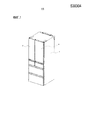
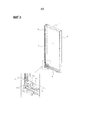
Фиг.1 представляет собой перспективный вид для иллюстрации всего холодильника в соответствии с вариантом осуществления 1 настоящего изобретения.Figure 1 is a perspective view to illustrate the entire refrigerator in accordance with
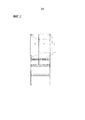
Фиг.2 представляет собой вид спереди всего холодильника в соответствии с вариантом осуществления 1 настоящего изобретения.Figure 2 is a front view of the entire refrigerator in accordance with
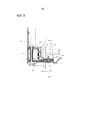
Фиг.3 представляет собой увеличенный вид участка вокруг верхнего шарнира, показанного на фиг.2.Figure 3 is an enlarged view of the area around the upper hinge shown in figure 2.
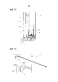
Фиг.4 представляет собой увеличенный вид участка вокруг нижнего шарнира, показанного на фиг.2.FIG. 4 is an enlarged view of a portion around the lower hinge shown in FIG.
Фиг.5 представляет собой вид с разнесением деталей поворотной двери для использования в холодильнике в соответствии с вариантом осуществления 1 настоящего изобретения.5 is an exploded view of a pivot door for use in a refrigerator in accordance with
Фиг.6 представляет собой перспективный вид второго усиливающего элемента для использования в холодильнике в соответствии с вариантом осуществления 1 настоящего изобретения.6 is a perspective view of a second reinforcing element for use in a refrigerator in accordance with
Фиг.7 представляет собой вертикальный разрез участка вокруг поворотной двери холодильника в соответствии с вариантом осуществления 1 настоящего изобретения, если смотреть с боковой поверхности.7 is a vertical sectional view of a portion around a pivot door of a refrigerator in accordance with
Фиг.8 представляет собой перспективный вид поворотной двери холодильника в соответствии с вариантом осуществления 1 настоящего изобретения.FIG. 8 is a perspective view of a pivot door of a refrigerator in accordance with
Фиг.9 представляет собой разрез, взятый по линии X-X на Фиг.8.Fig.9 is a section taken along the line X-X in Fig.8.
Фиг.10 представляет собой разрез, взятый по линии Y-Y на Фиг.9.Figure 10 is a section taken along the line Y-Y in Figure 9.
Фиг.11 представляет собой перспективный вид второго усиливающего элемента для использования в холодильнике в соответствии с вариантом осуществления 2 настоящего изобретения.11 is a perspective view of a second reinforcing element for use in a refrigerator in accordance with
Описание вариантов осуществленияDescription of Embodiments
[0010][0010]
Варианты осуществления настоящего изобретения будут описаны в дальнейшем со ссылкой на чертежи. Настоящее изобретение не ограничено на вариантах осуществления, описанных ниже. На чертежах, размерные взаимосвязи между составными элементами могут отличаться от размерных взаимосвязей между фактическими составными элементами. Термины "верхний", "нижний", "левый" и "правый" ниже представляют собой направления, если на холодильник смотреть с его передней стороны.Embodiments of the present invention will be described hereinafter with reference to the drawings. The present invention is not limited to the embodiments described below. In the drawings, dimensional relationships between constituent elements may differ from dimensional relationships between actual constituent elements. The terms “upper,” “lower,” “left,” and “right” below represent directions when viewed from the front of the refrigerator.
[0011][0011]
Вариант осуществления 1
Фиг.1 представляет собой перспективный вид для иллюстрации всего холодильника в соответствии с вариантом осуществления 1 настоящего изобретения. Фиг.2 представляет собой вид спереди всего холодильника в соответствии с вариантом осуществления 1 настоящего изобретения. Фиг.3 представляет собой увеличенный вид участка вокруг верхнего шарнира 2, показанного на фиг.2. Фиг.4 представляет собой увеличенный вид участка вокруг нижнего шарнира 3, показанного на фиг.2.Figure 1 is a perspective view to illustrate the entire refrigerator in accordance with
Участки вокруг верхнего шарнира 2 и нижнего шарнира 3 на фиг.2, участок вокруг верхнего шарнира 2 на фиг.3 и участок вокруг нижнего шарнира 3 на фиг.4 показаны прозрачными.The portions around the
[0012][0012]
Корпус 1, образующий холодильник в соответствии с вариантом осуществления 1, имеет проем на его передней части, как показано на фиг.1 и 2. Поворотные двери (правая поворотная дверь 4 и левая поворотная дверь 5), предназначенные для закрывания переднего проема, обеспечены таким образом, что поворотные двери свободно открываются и закрываются. Как показано на фиг.2, корпус 1 включает в себя верхние шарниры 2 и нижние шарниры 3 на верхнем и нижнем участках левой и правой боковых поверхностей. Как показано на фиг.3, верхние шарниры 2 выступают вниз. Как показано на фиг.4, нижние шарниры 3 выступают вверх. Как показано на фиг.1 и 2, правая поворотная дверь 4 поддерживается с возможностью вращения на верхнем шарнире 2 и нижнем шарнире 3 справа, и левая поворотная дверь 5 поддерживается с возможностью вращения на верхнем шарнире 2 и нижнем шарнире 3 слева.The
[0013][0013]
Фиг.5 представляет собой вид с разнесением деталей поворотной двери для использования в холодильнике в соответствии с вариантом осуществления 1 настоящего изобретения. Фиг.6 представляет собой перспективный вид второго усиливающего элемента 11 для использования в холодильнике в соответствии с вариантом осуществления 1 настоящего изобретения. Фиг.7 представляет собой вертикальный разрез участка вокруг поворотной двери холодильника в соответствии с вариантом осуществления 1 настоящего изобретения, если смотреть с его боковой стороны.5 is an exploded view of a pivot door for use in a refrigerator in accordance with
На фиг.5-7 показана конструкция правой поворотной двери 4. Левая поворотная дверь 5 имеет аналогичную конструкцию за исключением того, что левая поворотная дверь 5 имеет лево-правую симметрию с правой поворотной дверью 4.Figures 5-7 show the construction of the
[0014][0014]
Как показано на фиг.5, поворотная дверь в соответствии с вариантом осуществления 1, включает в себя нижнюю заглушку 6, верхнюю заглушку 7, левую заглушку 8, правую заглушку 9, первый усиливающий элемент 10, второй усиливающий элемент 11, шарнирный опорный элемент 12, элемент 13 внешней поверхности, элемент 14 внутренней поверхности, U-образный листовой металлический элемент 16 и шарнирный стопор 18.As shown in FIG. 5, the pivot door according to
[0015][0015]
Нижняя заглушка 6, верхняя заглушка 7, левая заглушка 8 и правая заглушка 9 выполнены из полимера. Каждая из нижней заглушки 6 и верхней заглушки 7 имеет захватные части (не показаны) на их обоих латеральных концах. Левая заглушка 8 и правая заглушка 9 имеют канавки (не показаны) в задних поверхностях в продольном направлении в местах, противоположных относительно захватных частей нижней заглушки 6 и верхней заглушки 7, когда соединены. Захватные части нижней заглушки 6 и верхней заглушки 7 сцепляются с канавками левой заглушки 8 и правой заглушки 9 таким образом, что верхняя заглушка 7, нижняя заглушка 6, правая заглушка 9 и левая заглушка 8 соединяются друг с другом и образуют форму рамы.The
[0016][0016]
Нижняя заглушка 6 включает в себя, на ее конце, полый участок 6a, который выступает вверх, является открытым на нижней части и имеет такую форму, чтобы размещать шарнирный опорный элемент 12. После размещения шарнирного опорного элемента 12 в полый участок 6a, нижняя заглушка 6 и шарнирный опорный элемент 12 вертикально размещаются между верхним U-образным листовым металлическим элементом 16 и нижним шарнирным стопором 18. U-образный листовой металлический элемент 16 имеет оба его конца, согнутые в одинаковом направлении таким образом, чтобы иметь по существу U-образную форму на виде сбоку. Эти элементы скреплены посредством винта 15.The
[0017][0017]
Первый усиливающий элемент 10 представляет собой металлический усиливающий элемент, имеющий по существу C-образную форму на виде сверху. Как показано на фиг.6, второй усиливающий элемент 11 представляет собой металлический усиливающий элемент, имеющий по существу L-образную форму на виде сбоку, и образован посредством соединения конца C-образного элемента 11a, имеющего по существу C-образную форму на виде сверху, и конца S-образного элемента 11b, имеющего его оба конца, согнутые в противоположных направлениях таким образом, чтобы иметь по существу S-образную форму на виде сбоку. S-образный элемент 11b имеет крючок 11ba на его продольном конце. Первый усиливающий элемент 10 прикреплен к задней поверхности левой заглушки 8 для усиления левой заглушки 8. Второй усиливающий элемент 11 прикреплен к задней поверхности правой заглушки 9 для усиления правой заглушки 9.The first reinforcing
[0018][0018]
В варианте осуществления 1 C-образный элемент 11a и S-образный элемент 11b соединяются таким образом, чтобы образовывать второй усиливающий элемент 11. Однако настоящее изобретение не ограничено на этой конструкции, и второй усиливающий элемент 11 может представлять собой выполненный за одно целое элемент.In
Второй усиливающий элемент 11 соответствует "усиливающему элементу" настоящего изобретения, крючок 11ba соответствует "первому крючку" настоящего изобретения, и S-образный элемент 11b соответствует "короткой стороне и первому крючку усиливающего элемента" настоящего изобретения.The second reinforcing
[0019][0019]
Здесь форма рамы, имеющая четыре стороны, получается посредством сцепления захватных частей нижней заглушки 6 и верхней заглушки 7 с канавками левой заглушки 8 и правой заглушки 9. При этом второй усиливающий элемент 11 размещен таким образом, что S-образный элемент 11b закрывает полый участок 6a нижней заглушки 6 (верхнюю поверхность и левую боковую поверхность полого участка 6a нижней заглушки 6). В варианте осуществления 1 нижняя заглушка 6, верхняя заглушка 7, левая заглушка 8 и правая заглушка 9 соединяются друг с другом таким образом, чтобы образовывать рамообразную заглушку. Однако настоящее изобретение не ограничено на этом примере, и рамообразная заглушка может представлять собой выполненный за одно целое элемент.Here, the shape of the frame having four sides is obtained by engaging the gripping parts of the
[0020][0020]
Заглушки, соединенные в форму рамы, присоединяются к четырем сторонам элемента 13 внешней поверхности, выполненного из имеющего плоскую форму армированного стекла, образующего переднюю поверхность поворотной двери, и четырем сторонам элемента 14 внутренней поверхности, выполненного из имеющего плоскую форму полимера, образующего внутреннюю поверхность поворотной двери, посредством адгезива (например, двусторонней клейкой ленты или клея). В этом присоединении пространство, заключенное между элементом 13 внешней поверхности и элементом 14 внутренней поверхности, заполняется пеноуретаном 17, который представляет собой теплоизолятор.Plugs connected in the form of a frame are attached to the four sides of the
[0021][0021]
В варианте осуществления 1 элемент 13 внешней поверхности поворотной двери представляет собой армированное стекло, имеющее плоскую пластинчатую форму. Однако настоящее изобретение не ограничено на этом, и элемент 13 внешней поверхности может представлять собой полимер, имеющий плоскую пластинчатую форму.In
U-образный листовой металлический элемент 16 соответствует "листовому металлическому элементу" настоящего изобретения, и заглушки, соединенные в форму рамы, соответствуют "рамообразной заглушке" настоящего изобретения.A U-shaped
[0022][0022]
Поворотная дверь, собранная вышеприведенным образом, поддерживается с возможностью вращения на нижних шарнирах 3, предусмотренных в корпусе 1, посредством использования шарнирных опорных элементов 12, как показано на фиг.7. Верхняя заглушка 7 имеет полый цилиндрический поддерживающий элемент (не показан), который поддерживает с возможностью вращения поворотную дверь на верхнем шарнире 2.The pivot door, assembled in the above manner, is rotatably supported on the lower hinges 3 provided in the
Хотя поворотная дверь свободно открывается и закрывается, когда поворотная дверь открывается до определенного угла или больше, шарнирный стопор 18 входит в контакт с нижним шарниром 3 для предотвращения дальнейшего открывания.Although the pivot door freely opens and closes when the pivot door opens to a certain angle or more, the
[0023][0023]
Фиг.8 представляет собой перспективный вид поворотной двери холодильника в соответствии с вариантом осуществления 1 настоящего изобретения. Фиг.9 представляет собой разрез, взятый по линии X-X на Фиг.8. Фиг.10 представляет собой разрез, взятый по линии Y-Y на Фиг.9.FIG. 8 is a perspective view of a pivot door of a refrigerator in accordance with
Как показано на фиг.8-10, крючок 11ba S-образного элемента 11b второго усиливающего элемента 11, прикрепленного к задней поверхности правой заглушки 9, предусмотрен в положении, где крючок 11ba перекрывается с (накладывается на) U-образным листовым металлическим элементом 16, если смотреть спереди. С учетом вариаций сборки ширина перекрывания в (вертикальном) направлении высоты (размер A) и ширина перекрывания в поперечном (горизонтальном) направлении (размер B) на фиг.9, предпочтительно, являются как можно большими и представляют собой такие размеры, которые обеспечивают перекрывание (наложение) крючка 11ba S-образного элемента 11b с U-образным листовым металлическим элементом 16. Отметим, что не требуется, чтобы ширина перекрывания в поперечном (горизонтальном) направлении (размер B) была больше размера C, который представляет собой длину от одного конца U-образного листового металлического элемента 16 до его центра.As shown in FIGS. 8-10, the hook 11ba of the S-shaped
[0024][0024]
Когда внутренняя часть поворотной двери заполнена пеноуретаном 17, S-образный элемент 11b второго усиливающего элемента 11 заделывается в пеноуретан 17. S-образный элемент 11b второго усиливающего элемента 11 обеспечивает анкерный эффект таким образом, что, даже когда правая заглушка 9 повреждается из-за, например, ухудшения вследствие старения, сопротивления окружающей среде, проблем с точки зрения прочности, образования трещин и теплового цикла, правая заглушка 9 не легко отделяется от пеноуретана 17, и, таким образом, прочность в направлении, обозначенном стрелкой Z на фиг.9, повышается. Анкерный эффект также может быть получен аналогичным образом посредством обеспечения S-образного элемента рядом с верхним шарниром 2 правой заглушки 9.When the inside of the pivot door is filled with
[0025][0025]
Как показано на фиг.10, крючок 11ba S-образного элемента 11b размещается между обоими концами U-образного листового металлического элемента 16 непосредственно или с предварительно заданным промежутком. Конкретно, крючок 11ba S-образного элемента 11b второго усиливающего элемента 11 расположен внутри U-образного листового металлического элемента 16, и крючок 11ba перекрывается с (накладывается на) U-образным листовым металлическим элементом 16. Соответственно, в случае, в котором армированное стекло, образующее элемент 13 внешней поверхности, разбивается, крючок 11ba S-образного элемента 11b второго усиливающего элемента 11 входит в контакт с U-образным листовым металлическим элементом 16 и зацепляется на нем, когда поворотная дверь выпадает. Таким образом, выпадание поворотной двери может быть предотвращено.As shown in FIG. 10, the hook 11ba of the S-shaped
[0026][0026]
В варианте осуществления 1 U-образный листовой металлический элемент 16 имеет по существу U-образную форму на виде сбоку. Однако U-образный листовой металлический элемент 16 не ограничен на этой форме. Только требуется, чтобы U-образный листовой металлический элемент 16 имел такую форму, которая обеспечивает возможность входа в контакт крючка 11ba S-образного элемента 11b второго усиливающего элемента 11 с U-образным листовым металлическим элементом 16 и зацепления на нем по меньшей мере, когда поворотная дверь выпадает вперед, таким образом выпадание поворотной двери может быть предотвращено.In
[0027][0027]
В варианте осуществления 1, крючок 11ba S-образного элемента 11b размещается между обоими концами U-образного листового металлического элемента 16 непосредственно или с предварительно заданным промежутком. Однако является достаточным то, что крючок 11ba и U-образный листовой металлический элемент 16 сцепляются, когда поворотная дверь выпадает, таким образом выпадание поворотной двери может быть предотвращено. Листовой металлический элемент может размещаться между крючками S-образного элемента 11b.In
[0028][0028]
Как описано выше, в холодильнике в соответствии с вариантом осуществления 1, S-образный элемент 11b второго усиливающего элемента 11 заделывается в пеноуретан 17, и S-образный элемент 11b второго усиливающего элемента 11 обеспечивает анкерный эффект. Таким образом, правая заглушка 9 не легко отделяется от пеноуретана 17. Кроме того, крючок 11ba S-образного элемента 11b второго усиливающего элемента 11 расположен внутри U-образного листового металлического элемента 16. Соответственно, даже в случае, в котором поворотная дверь открывается или закрывается с ее поврежденным элементом, крючок 11ba S-образного элемента 11b второго усиливающего элемента 11 входит в контакт с U-образным листовым металлическим элементом 16 и зацепляется на нем, когда поворотная дверь выпадает. Таким образом, выпадание поворотной двери может быть предотвращено.As described above, in the refrigerator according to
[0029][0029]
Вариант осуществления 2
Фиг.11 представляет собой перспективный вид второго усиливающего элемента 19 для использования в холодильнике в соответствии с вариантом осуществления 2 настоящего изобретения.11 is a perspective view of a second reinforcing
Теперь будет описан вариант осуществления 2. Составные элементы, уже описанные в варианте осуществления 1, не будут повторно описываться, и одинаковые ссылочные позиции относятся к одинаковым или эквивалентным составным элементам относительно составных элементов варианта осуществления 1.
Второй усиливающий элемент 19 в соответствии с вариантом осуществления 2 выполнен посредством соединения C-образного элемента 19a и S-образного элемента 19b друг с другом образом, аналогичным варианту осуществления 1, но дополнительно к крючку 19ba, образованному на продольном конце S-образного элемента 19b, крючок 19bb предусмотрен на латеральном конце S-образного элемента 19b и имеет отверстие 19bc, образованное в его центре. Этот крючок 19bb повышает адгезию между правой заглушкой 9 и пеноуретаном 17, таким образом может быть получена конструкция, имеющая высокое сопротивление отделению.The second reinforcing
Крючок 19bb соответствует "второму крючку" настоящего изобретения.The hook 19bb corresponds to the “second hook” of the present invention.
[0030][0030]
Отметим, что внутренний угол поворотной двери, особенно полый участок 6a нижней заглушки 6, имеет сложную форму, таким образом канал для пеноуретана 17 является узким. Соответственно, при заполнении пеноуретаном 17, крючок 19bb S-образного элемента 19b может препятствовать протеканию пеноуретана 17. Однако отверстие 19bc, образованное в крючке 19bb, может повышать способность к протеканию.Note that the inner corner of the pivot door, especially the
Крючок 19bb может быть образован только на одном латеральном конце S-образного элемента 19b или на каждом латеральном конце S-образного элемента 19b. Однако конфигурация, в которой крючок 19bb образован на каждом латеральном конце, получает большую адгезию между правой заглушкой 9 и пеноуретаном 17 и, таким образом, имеет большее сопротивление отделению.The hook 19bb may be formed at only one lateral end of the S-shaped
[0031][0031]
Вариант осуществления 3
Теперь будет описан вариант осуществления 3. Составные элементы, уже описанные в варианте осуществления 1, не будут повторно описываться, и одинаковые ссылочные позиции относятся к одинаковым или эквивалентным составным элементам относительно составных элементов варианта осуществления 1.
В варианте осуществления 3 твердый материал, например металлическая пластина или пленка, имеющая прочность, по существу, равную или большую прочности металлической пластины, приклеивается к задней поверхности армированного стекла, образующего элемент 13 внешней поверхности поворотной двери. Эта конструкция обеспечивает возможность входа в контакт металлической пластины или пленки с U-образным листовым металлическим элементом 16 и зацепления на нем, даже когда армированное стекло повреждено. Таким образом, выпадание поворотной двери может быть предотвращено.In
[0032][0032]
Вариант осуществления 4
Теперь будет описан вариант осуществления 4. Составные элементы, уже описанные в варианте осуществления 1, не будут повторно описываться, и одинаковые ссылочные позиции относятся к одинаковым или эквивалентным составным элементам относительно составных элементов варианта осуществления 1.
В варианте осуществления 4 материал, например чувствительная к давлению бумага, которая изменяет свой цвет при прикладывании давления, приклеивается к задней поверхности армированного стекла, образующего элемент 13 внешней поверхности поворотной двери. В этой конструкции, когда армированное стекло получает такой сильный удар, который вызывает образование трещин в армированном стекле, цвет подвергнувшегося удару участка изменяется. Таким образом, контрмеры, например техническое обслуживание или замена поворотных дверей, могут своевременно предприниматься.In
Перечень ссылочных обозначенийReference List
[0033][0033]
1 корпус, 2 верхний шарнир, 3 нижний шарнир, 4 левая поворотная дверь, 5 правая поворотная дверь, 6 нижняя заглушка, 6a полый участок, 7 верхняя заглушка, 8 левая заглушка, 9 правая заглушка, 10 первый усиливающий элемент, 11 второй усиливающий элемент, 11a C-образный элемент, 11b S-образный элемент, 11ba крючок, 12 шарнирные опорные элементы, 13 элемент внешней поверхности, 14 элемент внутренней поверхности, 15 винт, 16 U-образный листовой металлический элемент, 17 пеноуретан, 18 шарнирный стопор, 19 второй усиливающий элемент, 19a C-образный элемент, 19b S-образный элемент, 19ba крючок, 19bb крючок, 19bc отверстие.1 body, 2 upper hinge, 3 lower hinge, 4 left pivot door, 5 right pivot door, 6 lower plug, 6a hollow section, 7 upper plug, 8 left plug, 9 right plug, 10 first reinforcing element, 11 second reinforcing
Claims (36)
Applications Claiming Priority (3)
| Application Number | Priority Date | Filing Date | Title |
|---|---|---|---|
| JP2014123406A JP6289281B2 (en) | 2014-06-16 | 2014-06-16 | refrigerator |
| JP2014-123406 | 2014-06-16 | ||
| PCT/JP2015/053108 WO2015194203A1 (en) | 2014-06-16 | 2015-02-04 | Refrigerator |
Publications (1)
| Publication Number | Publication Date |
|---|---|
| RU2647915C1 true RU2647915C1 (en) | 2018-03-21 |
Family
ID=54935203
Family Applications (1)
| Application Number | Title | Priority Date | Filing Date |
|---|---|---|---|
| RU2017101080A RU2647915C1 (en) | 2014-06-16 | 2015-02-04 | Refrigerator |
Country Status (9)
| Country | Link |
|---|---|
| JP (1) | JP6289281B2 (en) |
| CN (1) | CN105300014B (en) |
| AU (1) | AU2015275505B2 (en) |
| HK (1) | HK1219997A1 (en) |
| MY (1) | MY180032A (en) |
| RU (1) | RU2647915C1 (en) |
| SG (1) | SG11201608944XA (en) |
| TW (1) | TWI585352B (en) |
| WO (1) | WO2015194203A1 (en) |
Families Citing this family (2)
| Publication number | Priority date | Publication date | Assignee | Title |
|---|---|---|---|---|
| WO2018101955A1 (en) * | 2016-12-02 | 2018-06-07 | Whirlpool Corporation | Hinge support assembly |
| WO2023013842A1 (en) * | 2021-08-05 | 2023-02-09 | 삼성전자주식회사 | Refrigerator and home appliance |
Citations (3)
| Publication number | Priority date | Publication date | Assignee | Title |
|---|---|---|---|---|
| WO2007094523A1 (en) * | 2006-02-15 | 2007-08-23 | Lg Electronics Inc. | Door supporting device for refrigerator |
| US20120104922A1 (en) * | 2010-10-29 | 2012-05-03 | Sanyo Electric Co., Ltd. | Hinge device and ultra-deep freezer using the same |
| RU2478174C2 (en) * | 2007-12-21 | 2013-03-27 | Бсх Бош Унд Сименс Хаусгерете Гмбх | Domestic appliance door and domestic appliance with such door |
Family Cites Families (10)
| Publication number | Priority date | Publication date | Assignee | Title |
|---|---|---|---|---|
| JPS6448586U (en) * | 1987-09-18 | 1989-03-24 | ||
| JPH05322436A (en) * | 1992-05-26 | 1993-12-07 | Matsushita Refrig Co Ltd | Heat insulating door |
| JPH08121943A (en) * | 1994-10-25 | 1996-05-17 | Hitachi Ltd | Handle attaching structure for refrigerator |
| JP3636040B2 (en) * | 2000-06-30 | 2005-04-06 | ダイキン工業株式会社 | refrigerator |
| JP2002213865A (en) * | 2001-01-15 | 2002-07-31 | Sanyo Electric Co Ltd | Cooling storage chamber |
| JP2004286050A (en) * | 2003-03-19 | 2004-10-14 | Matsushita Refrig Co Ltd | Vacuum heat insulation material, heat insulation box, and method for checking recess in vacuum heat insulation material |
| JP2013088025A (en) * | 2011-10-18 | 2013-05-13 | Hoshizaki Electric Co Ltd | Door device for cooling storage |
| CN202559929U (en) * | 2012-04-25 | 2012-11-28 | 珠海格力电器股份有限公司 | Hinge assembly and refrigerator provided with hinge assembly |
| CN103375078B (en) * | 2012-04-25 | 2015-12-02 | 珠海格力电器股份有限公司 | Hinge component and there is the refrigerator of this hinge component |
| CN204718257U (en) * | 2014-06-16 | 2015-10-21 | 三菱电机株式会社 | Refrigerator |
-
2014
- 2014-06-16 JP JP2014123406A patent/JP6289281B2/en active Active
-
2015
- 2015-02-04 AU AU2015275505A patent/AU2015275505B2/en active Active
- 2015-02-04 MY MYPI2016704605A patent/MY180032A/en unknown
- 2015-02-04 WO PCT/JP2015/053108 patent/WO2015194203A1/en active Application Filing
- 2015-02-04 SG SG11201608944XA patent/SG11201608944XA/en unknown
- 2015-02-04 RU RU2017101080A patent/RU2647915C1/en active
- 2015-02-26 TW TW104106178A patent/TWI585352B/en active
- 2015-05-29 CN CN201510289076.5A patent/CN105300014B/en active Active
-
2016
- 2016-07-08 HK HK16107980.9A patent/HK1219997A1/en unknown
Patent Citations (3)
| Publication number | Priority date | Publication date | Assignee | Title |
|---|---|---|---|---|
| WO2007094523A1 (en) * | 2006-02-15 | 2007-08-23 | Lg Electronics Inc. | Door supporting device for refrigerator |
| RU2478174C2 (en) * | 2007-12-21 | 2013-03-27 | Бсх Бош Унд Сименс Хаусгерете Гмбх | Domestic appliance door and domestic appliance with such door |
| US20120104922A1 (en) * | 2010-10-29 | 2012-05-03 | Sanyo Electric Co., Ltd. | Hinge device and ultra-deep freezer using the same |
Also Published As
| Publication number | Publication date |
|---|---|
| CN105300014A (en) | 2016-02-03 |
| AU2015275505A1 (en) | 2016-11-24 |
| WO2015194203A1 (en) | 2015-12-23 |
| MY180032A (en) | 2020-11-20 |
| HK1219997A1 (en) | 2017-04-21 |
| TW201606248A (en) | 2016-02-16 |
| SG11201608944XA (en) | 2016-12-29 |
| CN105300014B (en) | 2017-10-27 |
| JP2016003801A (en) | 2016-01-12 |
| AU2015275505B2 (en) | 2017-07-20 |
| TWI585352B (en) | 2017-06-01 |
| JP6289281B2 (en) | 2018-03-07 |
Similar Documents
| Publication | Publication Date | Title |
|---|---|---|
| CN106993385B (en) | Bent bottom case and display device | |
| ES2330660T3 (en) | QUICK RECOVERY HINGE TO SUPPORT A CLOSURE ELEMENT. | |
| USD603694S1 (en) | Door wedge | |
| RU2647915C1 (en) | Refrigerator | |
| US9061688B2 (en) | Bottom door device and hopper car having the same | |
| US8353564B2 (en) | Door assembly and refrigerator having the same | |
| KR101317921B1 (en) | Auto-seal Packing equipment of Door for Vessel | |
| CN204260533U (en) | Cooking apparatus | |
| JP6562682B2 (en) | refrigerator | |
| KR101923397B1 (en) | Folding Door Provided With Dual Frame Assembling Type Door Leaf | |
| CN207895539U (en) | Automatic vending machine cabinet and automatic vending machine | |
| CN207440899U (en) | A kind of outdoor use Self-help vending machine equipped with roof truss outline border | |
| CN204718257U (en) | Refrigerator | |
| FR2972750B1 (en) | DEVICE FOR FIXING A WINDOW OPENABLE BY ROTATION, GLAZING AND METHOD FOR PRODUCING THE WINDOW | |
| RU2406948C2 (en) | Refrigerating appliance with simplified door opening | |
| JP2017026251A (en) | refrigerator | |
| JP2016003801A5 (en) | ||
| KR20150092556A (en) | System door | |
| CN214696313U (en) | Assembled building curtain | |
| KR100796720B1 (en) | Open and shut apparatus for cellular phone | |
| CN203068906U (en) | Refrigerator glass door body and side opening door type refrigerator | |
| EP3272980B1 (en) | Museum showcase with quadrilateral hinge having a hook for holding the door in a closed position | |
| BR112021007694A2 (en) | insulated glazing that forms a door or window opening panel, which is frameless in at least part of its periphery | |
| US9820586B1 (en) | Museum showcase with an articulated quadrilateral hinge, having a hook for holding it in a closed position | |
| KR20110064782A (en) | A hinge structure of luggage door |