RU2646373C1 - Device of adaptive regulation based on the joint maximum principle - Google Patents
Device of adaptive regulation based on the joint maximum principle Download PDFInfo
- Publication number
- RU2646373C1 RU2646373C1 RU2016149888A RU2016149888A RU2646373C1 RU 2646373 C1 RU2646373 C1 RU 2646373C1 RU 2016149888 A RU2016149888 A RU 2016149888A RU 2016149888 A RU2016149888 A RU 2016149888A RU 2646373 C1 RU2646373 C1 RU 2646373C1
- Authority
- RU
- Russia
- Prior art keywords
- input
- output
- unit
- block
- multiplication
- Prior art date
Links
Images

Classifications
-
- G—PHYSICS
- G05—CONTROLLING; REGULATING
- G05B—CONTROL OR REGULATING SYSTEMS IN GENERAL; FUNCTIONAL ELEMENTS OF SUCH SYSTEMS; MONITORING OR TESTING ARRANGEMENTS FOR SUCH SYSTEMS OR ELEMENTS
- G05B11/00—Automatic controllers
-
- G—PHYSICS
- G05—CONTROLLING; REGULATING
- G05B—CONTROL OR REGULATING SYSTEMS IN GENERAL; FUNCTIONAL ELEMENTS OF SUCH SYSTEMS; MONITORING OR TESTING ARRANGEMENTS FOR SUCH SYSTEMS OR ELEMENTS
- G05B15/00—Systems controlled by a computer
-
- G—PHYSICS
- G06—COMPUTING OR CALCULATING; COUNTING
- G06F—ELECTRIC DIGITAL DATA PROCESSING
- G06F17/00—Digital computing or data processing equipment or methods, specially adapted for specific functions
-
- G—PHYSICS
- G06—COMPUTING OR CALCULATING; COUNTING
- G06G—ANALOGUE COMPUTERS
- G06G7/00—Devices in which the computing operation is performed by varying electric or magnetic quantities
- G06G7/12—Arrangements for performing computing operations, e.g. operational amplifiers specially adapted therefor
- G06G7/30—Arrangements for performing computing operations, e.g. operational amplifiers specially adapted therefor for interpolation or extrapolation
Landscapes
- Feedback Control In General (AREA)
Abstract
Description
Изобретение относится к области цифровых систем управления и может быть использовано для решения задач быстродействия в автоматизированных системах, например в радиотехнике, для фазовой автоподстройки частоты.The invention relates to the field of digital control systems and can be used to solve performance problems in automated systems, for example, in radio engineering, for phase locked loop.
Известны регуляторы с переменной структурой (см. Кузьменко А.А., Попов А.Н., Радионов И.А. Нелинейное робастное управление возбуждением синхронного генератора: синергетическая система с переменной структурой // Адаптивные и робастные системы. Таганрог. Информатика и системы управления, 2014. С. 130-139). Их недостатками являются релейный характер управления, что приводит к сложностям практической реализации подобных технических решений и сопряжено с большими энергетическими затратами, а также относительно низкое быстродействие.Known regulators with variable structure (see Kuzmenko A.A., Popov A.N., Radionov I.A. Non-linear robust control of excitation of a synchronous generator: synergetic system with variable structure // Adaptive and robust systems. Taganrog. Informatics and control systems , 2014.S. 130-139). Their disadvantages are the relay nature of control, which leads to difficulties in the practical implementation of such technical solutions and is associated with high energy costs, as well as relatively low speed.
Наиболее близким по технической сущности и достигаемому результату является устройство (см. патент RU №2601143, G06G 7/30, Н03Н 17/06, опубл. 27.10.2016 г.), адаптивный экстраполятор, содержащий блок формирования суммы, первый, второй и третий блоки формирования умножения, блок хранения констант, блок отношения, первый и второй блок вычисления модуля, первый и второй блок вычитания.The closest in technical essence and the achieved result is a device (see patent RU No. 2601143, G06G 7/30, Н03Н 17/06, publ. 10/27/2016), an adaptive extrapolator containing the summing unit, the first, second and third multiplication generation units, constant storage unit, ratio unit, first and second unit calculation unit, first and second subtraction unit.
Недостаток такого решения - резкое возрастание управляющего воздействия в терминальной точке фазовой плоскости, что ограничивает возможность практического применения в механических системах.The disadvantage of this solution is a sharp increase in the control action at the terminal point of the phase plane, which limits the possibility of practical application in mechanical systems.
Задача изобретения - увеличение быстродействия автоматизированных систем.The objective of the invention is to increase the speed of automated systems.
Она достигается использованием объединенного принципа максимума для построения устройства адаптивного регулирования за счет аппроксимации релейного режима функционирования и синтезирующей функции, которая не допускает резкого увеличения управляющего воздействия в окрестности терминальной точки.It is achieved by using the combined maximum principle to build an adaptive control device by approximating the relay mode of operation and a synthesizing function that does not allow a sharp increase in the control action in the vicinity of the terminal point.
Сущность изобретения заключается в том, что устройство адаптивного регулирования на основе объединенного принципа максимума, содержащее блоки: блок формирования суммы, первый, второй и третий блоки формирования умножения, блок хранения констант, блок вычисления отношения 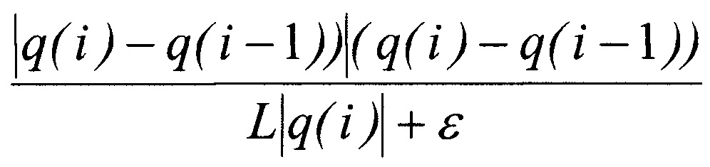
Техническим результатом является увеличение быстродействия автоматизированных систем, что достигается устройством адаптивного регулирования на основе объединенного принципа максимума, которое содержит: блок линии задержки; блоки формирования модуля; блоки разности; блоки умножения; блока отношения; блок вычисления функции tan; блок хранения констант; блок формирования суммы.The technical result is to increase the speed of automated systems, which is achieved by an adaptive control device based on the combined maximum principle, which contains: a delay line unit; module formation blocks; difference blocks; multiplication blocks; relationship block; tan function calculation unit; constant storage unit; block forming the amount.
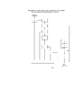
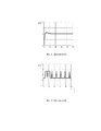
Сущность изобретения поясняется чертежом, где на фиг. 1 представлено устройство адаптивного регулирования на основе объединенного принципа максимума, а результаты математического моделирования приведены на фигурах 2, 3, 4: фиг. 2 - динамика (1), фиг. 3 - динамика (4), фиг. 4 - изменение состояния.The invention is illustrated in the drawing, where in FIG. 1 shows an adaptive control device based on the combined maximum principle, and the results of mathematical modeling are shown in figures 2, 3, 4: FIG. 2 - dynamics (1), FIG. 3 - dynamics (4), FIG. 4 - state change.
Вход устройства соединен со входом блока формирования линии задержки 1, входом блока формирования модуля 2, со вторым входом блока вычисления разности 3 и вторым входом блока вычисления разности 4, выход которого соединен со вторым входом блока формирования умножения 5 и входом блока формирования модуля 6, выход которого соединен с первым входом блока 5, выход которого соединен со вторым входом блока вычисления отношения 7, выход которого соединен с первым входом блока формирования умножения 8, выход которого соединен с первым входом блока вычисления разности 3, выход которого соединен со входом блока формирования функции tan 9, выход которого соединен со вторым входом блока формирования умножения 10, выход которого является выходом устройства, первый выход блока хранения констант 11 соединен со входом первым блока 10, второй выход блока 11 соединен со вторым входом блока 8, третий выход блока 11 соединен с первым входом блока формирования суммы 12, выход которого соединен с первым входом блока 7, выход четвертый блока 11 соединен с первым входом блока формирования умножения 13, выход которого соединен со вторым входом блока 12, выход блока 1 соединен с первым входом блока 4, выход блока 2 соединен со вторым входом блока 13.The input of the device is connected to the input of the block forming the
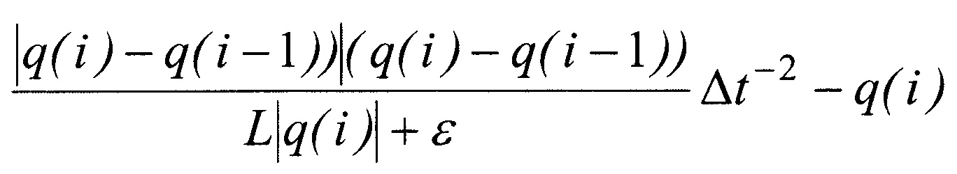
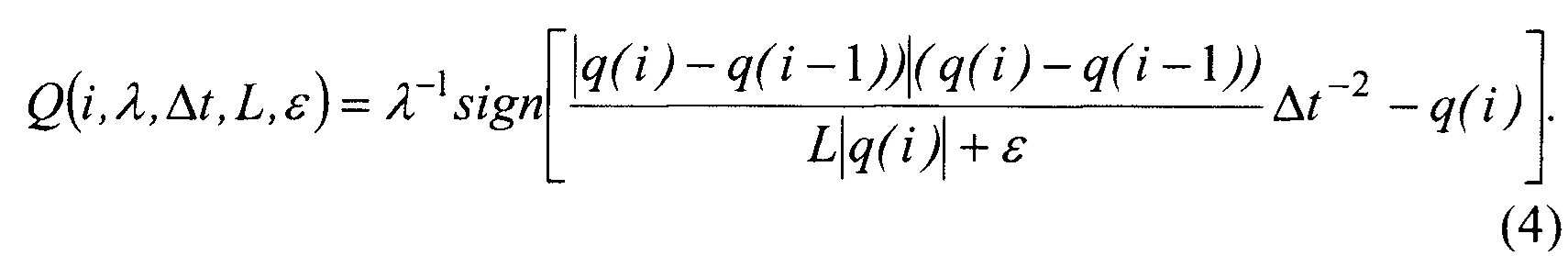
Пояснить работу устройства позволят следующие выкладки. Структура обратной связи как функции обобщенных координат в дискретном времени имеет вид:Explain the operation of the device will allow the following calculations. The feedback structure as a function of generalized coordinates in discrete time has the form:
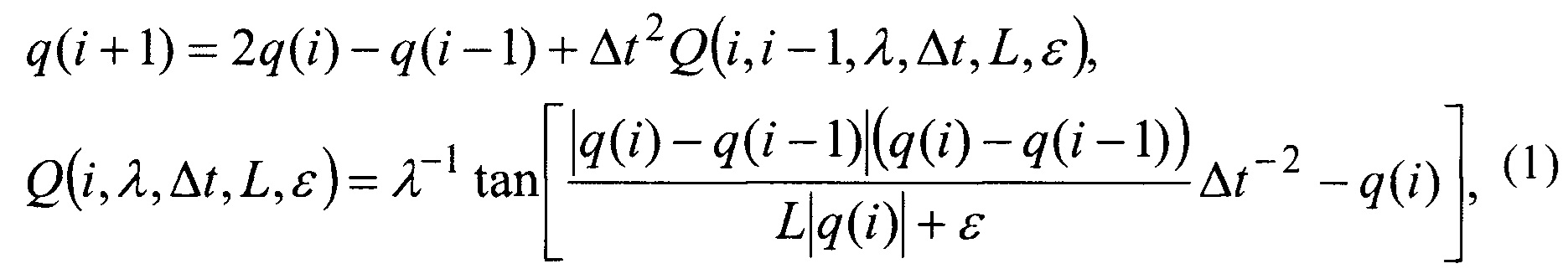
где i - текущий момент времени, q(i) - текущее значение переменной состояния, Δt - интервал дискретизации, λ-1 - неопределенный множитель Лагранжа, L - константа, зависящая от формы линии переключения, ε - константа, определяющая сдвиг линии переключения.where i is the current time, q (i) is the current value of the state variable, Δt is the sampling interval, λ -1 is the indefinite Lagrange multiplier, L is a constant depending on the shape of the switching line, ε is a constant that determines the shift of the switching line.
Устройство работает следующим образом: за один такт, равный шагу дискретизации, до начала работы устройства значение q(i) подается на вход блока формирования линии задержки 1, на вход блока формирования модуля 2, на вход второй блока вычисления разности 3 и на вход второй блока вычисления разности 4, с выхода которого значение q(i)-q(i-1) поступает на вход второй блока формирования умножения 5 и на вход блока формирования модуля 6, с выхода которого значение |q(i)-q(i-1))| поступает на вход первый блока 5, с выхода которого значение |q(i)-q(i-1))|(q(i)-q(i-1)) поступает на вход второй блока вычисления отношения 7, с выхода которого значение 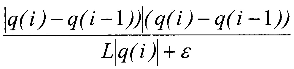


второй блока формирования умножения 10, с выхода которого значение 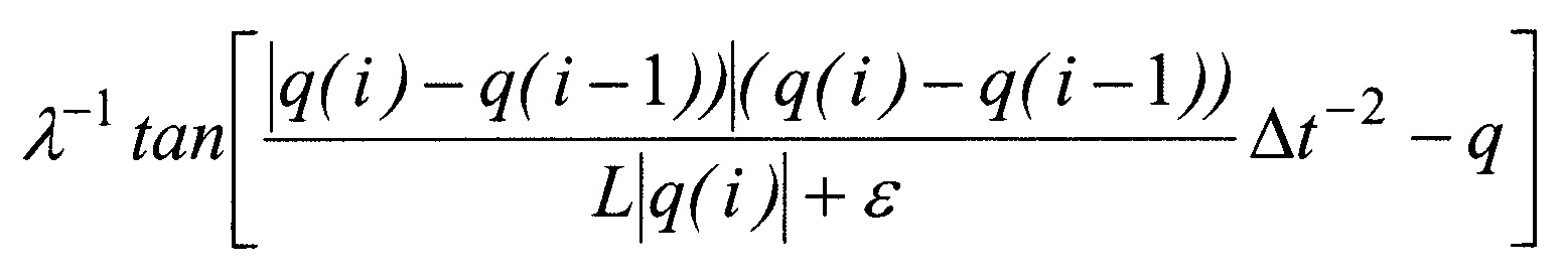
Пример. Рассмотрим динамическую систему второго порядкаExample. Consider a second-order dynamical system
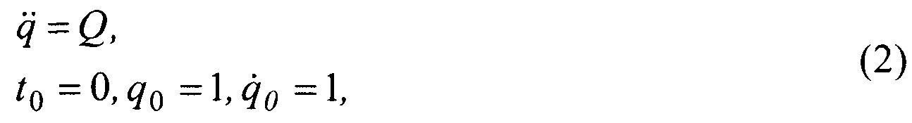
и поставим задачу синтеза управления, обеспечивающего минимум функционалуand set the task of control synthesis providing a minimum of functionality
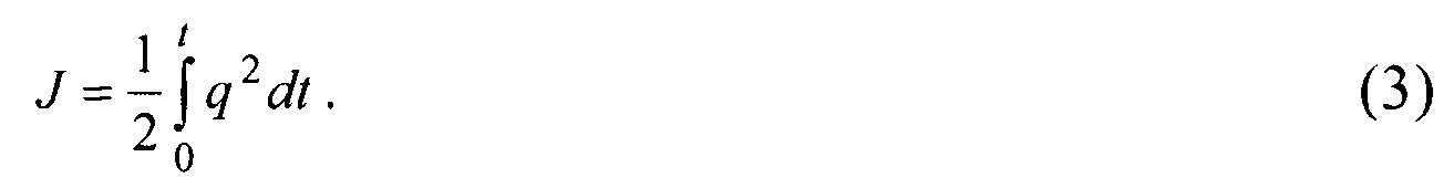
Оценка эффективности (1) произведена на основе сравнения с решением, которое определяется выражениемEvaluation of the effectiveness of (1) is based on a comparison with a solution that is determined by the expression
Результаты математического моделирования приведены на фигурах 2, 3 и 4. Видно, что выражение (1) в сравнении с выражением (4) обеспечивает большую скорость сходимости, в этом случае исключается чаттеринг-режим, порождаемый разрывным (релейным) управлением выражения (4), а использование отличной от патента RU №2601143 синтезирующей функции не позволяет управляющему воздействию резко возрастать в терминальной точке фазовой плоскости.The results of mathematical modeling are shown in figures 2, 3 and 4. It can be seen that expression (1) in comparison with expression (4) provides a high convergence rate, in this case, the chatter mode generated by the discontinuous (relay) control of expression (4) is excluded and the use of a synthesizing function other than RU patent No. 2601143 does not allow the control action to increase sharply at the terminal point of the phase plane.
Результаты, приведенные в примере, позволяют сделать заключение о достижении заявленного технического результата.The results shown in the example allow us to conclude that the claimed technical result is achieved.
Claims (1)
Priority Applications (1)
| Application Number | Priority Date | Filing Date | Title |
|---|---|---|---|
| RU2016149888A RU2646373C1 (en) | 2016-12-20 | 2016-12-20 | Device of adaptive regulation based on the joint maximum principle |
Applications Claiming Priority (1)
| Application Number | Priority Date | Filing Date | Title |
|---|---|---|---|
| RU2016149888A RU2646373C1 (en) | 2016-12-20 | 2016-12-20 | Device of adaptive regulation based on the joint maximum principle |
Publications (1)
| Publication Number | Publication Date |
|---|---|
| RU2646373C1 true RU2646373C1 (en) | 2018-03-02 |
Family
ID=61568548
Family Applications (1)
| Application Number | Title | Priority Date | Filing Date |
|---|---|---|---|
| RU2016149888A RU2646373C1 (en) | 2016-12-20 | 2016-12-20 | Device of adaptive regulation based on the joint maximum principle |
Country Status (1)
| Country | Link |
|---|---|
| RU (1) | RU2646373C1 (en) |
Cited By (2)
| Publication number | Priority date | Publication date | Assignee | Title |
|---|---|---|---|---|
| RU2697728C1 (en) * | 2018-12-19 | 2019-08-19 | федеральное государственное бюджетное образовательное учреждение высшего образования "Донской государственный технический университет" (ДГТУ) | Automatic systems control device with structural uncertainty |
| RU2780197C1 (en) * | 2021-09-02 | 2022-09-20 | Антон Сергеевич Пеньков | Extrapolator with adaptation for target functions |
Citations (4)
| Publication number | Priority date | Publication date | Assignee | Title |
|---|---|---|---|---|
| SU1064271A1 (en) * | 1982-06-04 | 1983-12-30 | Сибирский ордена Трудового Красного Знамени металлургический институт им.Серго Орджоникидзе | Adaptive control unit |
| US8005554B2 (en) * | 2008-03-07 | 2011-08-23 | Snecma | Device for controlling a regulated system, and an engine including such a device |
| RU2475828C1 (en) * | 2011-12-29 | 2013-02-20 | Федеральное государственное унитарное предприятие "Научно-производственное объединение им. С.А. Лавочкина" | Apparatus for generating control action to provide stable operation of complex engineering systems |
| RU2601143C1 (en) * | 2015-05-25 | 2016-10-27 | Федеральное государственное бюджетное образовательное учреждение высшего образования "Донской государственный технический университет" | Adaptive extrapolator |
-
2016
- 2016-12-20 RU RU2016149888A patent/RU2646373C1/en active
Patent Citations (4)
| Publication number | Priority date | Publication date | Assignee | Title |
|---|---|---|---|---|
| SU1064271A1 (en) * | 1982-06-04 | 1983-12-30 | Сибирский ордена Трудового Красного Знамени металлургический институт им.Серго Орджоникидзе | Adaptive control unit |
| US8005554B2 (en) * | 2008-03-07 | 2011-08-23 | Snecma | Device for controlling a regulated system, and an engine including such a device |
| RU2475828C1 (en) * | 2011-12-29 | 2013-02-20 | Федеральное государственное унитарное предприятие "Научно-производственное объединение им. С.А. Лавочкина" | Apparatus for generating control action to provide stable operation of complex engineering systems |
| RU2601143C1 (en) * | 2015-05-25 | 2016-10-27 | Федеральное государственное бюджетное образовательное учреждение высшего образования "Донской государственный технический университет" | Adaptive extrapolator |
Cited By (2)
| Publication number | Priority date | Publication date | Assignee | Title |
|---|---|---|---|---|
| RU2697728C1 (en) * | 2018-12-19 | 2019-08-19 | федеральное государственное бюджетное образовательное учреждение высшего образования "Донской государственный технический университет" (ДГТУ) | Automatic systems control device with structural uncertainty |
| RU2780197C1 (en) * | 2021-09-02 | 2022-09-20 | Антон Сергеевич Пеньков | Extrapolator with adaptation for target functions |
Similar Documents
| Publication | Publication Date | Title |
|---|---|---|
| Morrison | Some observations regarding brackets and dissipation | |
| Geng et al. | Modeling and implementation of an all digital phase-locked-loop for grid-voltage phase detection | |
| Lozi et al. | A new reliable numerical method for computing chaotic solutions of dynamical systems: the Chen attractor case | |
| RU2646373C1 (en) | Device of adaptive regulation based on the joint maximum principle | |
| Kuznetsov et al. | Analytical methods for computation of phase-detector characteristics and PLL design | |
| Vorotnikov et al. | Stability in part of the variables of “partial” equilibria of systems with aftereffect | |
| CN103390428A (en) | Method for synchronizing sampling to sinusoidal inputs | |
| Leonov et al. | Computation of phase detector characteristics in synchronization systems | |
| Anisimov et al. | Peculiarities of synthesis of parametrically robust modal control system with state observers | |
| Kafash et al. | Restarted state parameterization method for optimal control problems | |
| RU2017124498A (en) | ELECTRONIC FORMING DEVICE | |
| Kuznetsov et al. | Elegant analytic computation of phase detector characteristic for non-sinusoidal signals | |
| RU2613623C1 (en) | Terminal control device based on variational principles | |
| CN107153352A (en) | A kind of pulse generation method based on digital frequency synthesis technology | |
| Sastre et al. | Microcanonical ensemble simulation method applied to discrete potential fluids | |
| Kuznetsov et al. | Simulation of phase-locked loops in phase-frequency domain | |
| Emel’yanov et al. | Signal differentiation in automatic control systems | |
| Beigel et al. | Approximation of weak adjoints by reverse automatic differentiation of BDF methods | |
| Mokeev | Optimal filter synthesis | |
| Das et al. | Online identification of fractional order models with time delay: An experimental study | |
| RU2697728C1 (en) | Automatic systems control device with structural uncertainty | |
| Kuznetsov et al. | High-frequency analysis of phase-locked loop and phase detector characteristic computation | |
| Adimoolam et al. | Using complex zonotopes for stability verification | |
| Kuznetsov et al. | Nonlinear analysis of Costas loop circuit | |
| Kuznetsov et al. | Computation of the phase detector characteristic of classical PLL. |