RU2640887C1 - Flat efficient condenser-separator for microgravitation and transport applications - Google Patents
Flat efficient condenser-separator for microgravitation and transport applications Download PDFInfo
- Publication number
- RU2640887C1 RU2640887C1 RU2016152541A RU2016152541A RU2640887C1 RU 2640887 C1 RU2640887 C1 RU 2640887C1 RU 2016152541 A RU2016152541 A RU 2016152541A RU 2016152541 A RU2016152541 A RU 2016152541A RU 2640887 C1 RU2640887 C1 RU 2640887C1
- Authority
- RU
- Russia
- Prior art keywords
- separator
- liquid
- condenser
- channel
- capillary
- Prior art date
Links
- 239000007788 liquid Substances 0.000 claims description 49
- 239000003990 capacitor Substances 0.000 claims description 12
- 230000005486 microgravity Effects 0.000 claims description 8
- 238000005086 pumping Methods 0.000 claims description 6
- 238000001816 cooling Methods 0.000 abstract description 16
- 230000000694 effects Effects 0.000 abstract description 3
- 239000012530 fluid Substances 0.000 abstract description 3
- 238000010276 construction Methods 0.000 abstract 1
- 239000000126 substance Substances 0.000 abstract 1
- 239000007789 gas Substances 0.000 description 24
- 239000010408 film Substances 0.000 description 16
- 239000000203 mixture Substances 0.000 description 10
- 238000009833 condensation Methods 0.000 description 9
- 230000005494 condensation Effects 0.000 description 9
- 230000005484 gravity Effects 0.000 description 7
- 238000000926 separation method Methods 0.000 description 7
- 239000010409 thin film Substances 0.000 description 6
- 230000007423 decrease Effects 0.000 description 5
- 230000005499 meniscus Effects 0.000 description 5
- 238000001704 evaporation Methods 0.000 description 4
- XLYOFNOQVPJJNP-UHFFFAOYSA-N water Substances O XLYOFNOQVPJJNP-UHFFFAOYSA-N 0.000 description 4
- QGZKDVFQNNGYKY-UHFFFAOYSA-N Ammonia Chemical compound N QGZKDVFQNNGYKY-UHFFFAOYSA-N 0.000 description 2
- IJGRMHOSHXDMSA-UHFFFAOYSA-N Atomic nitrogen Chemical compound N#N IJGRMHOSHXDMSA-UHFFFAOYSA-N 0.000 description 2
- 230000015572 biosynthetic process Effects 0.000 description 2
- 230000008020 evaporation Effects 0.000 description 2
- 239000000446 fuel Substances 0.000 description 2
- 230000033001 locomotion Effects 0.000 description 2
- 238000004377 microelectronic Methods 0.000 description 2
- 239000000758 substrate Substances 0.000 description 2
- 229910021529 ammonia Inorganic materials 0.000 description 1
- 230000015556 catabolic process Effects 0.000 description 1
- 239000003814 drug Substances 0.000 description 1
- 230000010006 flight Effects 0.000 description 1
- 238000013178 mathematical model Methods 0.000 description 1
- 238000000034 method Methods 0.000 description 1
- 229910052757 nitrogen Inorganic materials 0.000 description 1
- 230000005514 two-phase flow Effects 0.000 description 1
Images
Landscapes
- Cooling Or The Like Of Electrical Apparatus (AREA)
Abstract
Description
Изобретение относится к области мини- и микросистем, которые используются в электронике, медицине, энергетике, аэрокосмической индустрии, на транспорте и могут применяться в устройствах для охлаждения электроники.The invention relates to the field of mini- and microsystems that are used in electronics, medicine, energy, the aerospace industry, in transport and can be used in devices for cooling electronics.
Известен способ, описанный в статье (Kabov О.А., Kuznetsov V.V., and Legros J-C., Heat transfer and film dynamic in shear-driven liquid film cooling system of microelectronic equipment, Second Int. Conference on Microchannels and Minichannels, Ed. S.G. Kandlikar, June 17-19, 2004, Rochester, NY, ASME, New York, pp. 687-694 (2004)), при котором охлаждение электронного компонента происходит за счет испарения тонкой пленки жидкости. Тонкая пленка диэлектрической жидкости FC-72 движется со спутным потоком газа (азота) в микроканале с электронными тепловыделяющими элементами. Электронные тепловыделяющие элементы могут быть расположены на одной стороне канала либо на двух противоположных сторонах канала. Система охлаждения включает конденсатор пара и сепаратор. В сепараторе жидкость отделяется от неконденсируемого газа и затем газ и жидкость отдельно вновь подаются в испарительную часть. Конструкция сепаратора детально не описана. Часто в подобных системах используют сепараторы самой простой конструкции, основанные на действии гравитации и разной плотности жидкости и газа.The known method described in the article (Kabov O.A., Kuznetsov VV, and Legros JC., Heat transfer and film dynamic in shear-driven liquid film cooling system of microelectronic equipment, Second Int. Conference on Microchannels and Minichannels, Ed. SG Kandlikar, June 17-19, 2004, Rochester, NY, ASME, New York, pp. 687-694 (2004)), in which the cooling of the electronic component is due to the evaporation of a thin film of liquid. A thin film of dielectric fluid FC-72 moves with a satellite stream of gas (nitrogen) in a microchannel with electronic fuel elements. Electronic fuel elements can be located on one side of the channel or on two opposite sides of the channel. The cooling system includes a steam condenser and a separator. In the separator, the liquid is separated from the non-condensable gas, and then the gas and liquid are separately separately fed back to the evaporation part. The design of the separator is not described in detail. Often in such systems, separators of the simplest design are used, based on the action of gravity and different densities of liquid and gas.
Основным недостатком данного технического решения является то, что сепаратор такого типа не может использоваться в условиях микрогравитации, а также на транспортных системах (летательные аппараты, автомобили), т.е. в условиях переменной гравитации. Кроме того, данные устройства достаточно громоздкие, процесс сепарации в них не может быть реализован с применением микро- и мини-каналов.The main disadvantage of this technical solution is that a separator of this type cannot be used in microgravity conditions, as well as on transport systems (aircraft, cars), i.e. under conditions of variable gravity. In addition, these devices are rather bulky; the separation process in them cannot be implemented using micro- and mini-channels.
Наиболее близкое техническое решение, которое можно рассматривать как прототип, описано в статье (Kabov O.A., Iorio C.S., Colinet P. and Legros J.C., Two-phase flow pattern and pressure drop in amicrochannel, Proc. First International Conferenceon Microchannels and Minichannels, Ed. S.G. Kandlikar, April 24-25, 2003, Rochester, NY, USA, pp. 465-472, 2003). Устройство содержит цилиндрический охлаждаемый конденсатор (внутритрубный конденсатор) с двумя цилиндрическими сепараторами. Первый сепаратор является основным. Отделение конденсата от парогазовой смеси происходит за счет резкого расширения и поворота жидкости на 90 градусов. Все количество неконденсируемого газа проходит во второй сепаратор, который служит для отделения оставшегося конденсата и улавливания возможных капель. Во втором сепараторе происходит отвод обедненной паром парогазовой смеси. Причем парогазовая смесь изменяет первоначальное направление течения на 180 градусов. Оба сепаратора имеют существенное сужение, где капиллярными силами постоянно удерживается жидкость. Данный конденсатор-сепаратор тестировался авторами как в земных условиях, так и в условиях кратковременной микрогравитации (22 секунды) в параболических полетах.The closest technical solution that can be considered as a prototype is described in the article (Kabov OA, Iorio CS, Colinet P. and Legros JC, Two-phase flow pattern and pressure drop in amicrochannel, Proc. First International Conferenceon Microchannels and Minichannels, Ed. SG Kandlikar, April 24-25, 2003, Rochester, NY, USA, pp. 465-472, 2003). The device comprises a cylindrical cooled condenser (in-tube condenser) with two cylindrical separators. The first separator is the main one. The condensate is separated from the vapor-gas mixture due to a sharp expansion and rotation of the liquid by 90 degrees. The entire amount of non-condensable gas passes into a second separator, which serves to separate the remaining condensate and trap possible drops. In the second separator, the steam-gas mixture is depleted of steam. Moreover, the gas-vapor mixture changes the initial direction of the flow by 180 degrees. Both separators have a significant narrowing, where the liquid is constantly held by capillary forces. This condenser-separator was tested by the authors both in terrestrial conditions and in the conditions of short-term microgravity (22 seconds) in parabolic flights.
Недостатки описанного выше технического решения:The disadvantages of the above technical solution:
1) сложность конструкции устройства и, как следствие, дороговизна за счет использования двух сепараторов;1) the complexity of the design of the device and, as a consequence, the high cost due to the use of two separators;
2) ограничение по увеличению мощности;2) restriction on increasing power;
Повышение мощности приведет к увеличению диаметра сепараторов и, неизбежно, к существенному увеличению габаритов системы.An increase in power will lead to an increase in the diameter of the separators and, inevitably, to a significant increase in the dimensions of the system.
3) возможность повторного испарения жидкости в сепараторах и соединяющей их трубке, которые являются не охлаждаемыми, и снижения эффективности сепарации;3) the possibility of re-evaporation of the liquid in the separators and the tube connecting them, which are not cooled, and reduce the separation efficiency;
4) сложность геометрической конструкции сепараторов.4) the complexity of the geometric design of the separators.
В случае их охлаждения потребуется дорогостоящая разветвленная охлаждающая система, состоящая из нескольких элементов, например, состоящая из нескольких Пельтье элементов.In case of their cooling, an expensive branched cooling system consisting of several elements, for example, consisting of several Peltier elements, will be required.
Задачей заявляемого изобретения является создание мощного и дешевого конденсатора-сепаратора для использования в условиях микрогравитации и транспортных приложений, способного существенно увеличить эффективность сепарации и при этом имеющего простое конструктивное исполнение, малые массу и габариты.The objective of the invention is the creation of a powerful and cheap condenser-separator for use in microgravity and transport applications, capable of significantly increasing the separation efficiency and at the same time having a simple design, small weight and dimensions.
Поставленная задача решается тем, что в плоском эффективном конденсаторе-сепараторе для микрогравитации и транспортных приложений, содержащем конденсатор и сепаратор, согласно изобретению конденсатор и сепаратор выполнены в виде плоского, охлаждаемого микро- или мини-канала высотой Н<lσ, где lσ - капиллярная постоянная жидкости, причем в плоскости продольного сечения, проходящей через боковые стенки микро- или мини-канала, конденсатор имеет форму прямоугольника шириной В, выбираемой из соотношения 20≥В/Н≥5, а сепаратор имеет форму трапеции, ширина меньшего основания которой равна В, а на боковых и торцевой стенках сепаратора вдоль линии пересечения их плоскостью продольного сечения выполнен капиллярный щелевой затвор, представляющий собой узкий плоский щелевой зазор, соединяющий внутренний объем сепаратора с полостью для откачки конденсата.The problem is solved in that in a flat efficient condenser-separator for microgravity and transport applications containing a capacitor and a separator, according to the invention, the capacitor and separator are made in the form of a flat, cooled micro- or mini-channel with a height of H <l σ , where l σ - the capillary constant of the liquid, and in the plane of the longitudinal section passing through the side walls of the micro- or mini-channel, the capacitor has the shape of a rectangle of width B, selected from the ratio of 20≥V / H≥5, and the separator has the shape of a drain tion, the width of the smaller base of which is B and the side and end walls of the separator along the line of intersection of the plane of the longitudinal section is formed capillary plane shutter, which is a narrow flat slit gap connecting the internal volume of the separator with the cavity for pumping condensate.
Используемая форма конденсатора обеспечивает интенсивную конденсацию пара за счет действия капиллярных сил и формирования тонкой пленки конденсата. Длина такой поверхности определяется конкретным приложением. Конструкция позволяет отводить конденсат в сепараторе на значительной длине и тем самым обеспечивать значительный расход конденсата по сравнению с прототипом. Устройство может работать в условиях нормальной гравитации, микрогравитации и переменной гравитации.The used form of the condenser provides intense vapor condensation due to the action of capillary forces and the formation of a thin film of condensate. The length of such a surface is determined by the particular application. The design allows to drain the condensate in the separator over a considerable length and thereby provide a significant flow of condensate in comparison with the prototype. The device can operate under normal gravity, microgravity and variable gravity.
Известно, что при конденсации в тонких пленках жидкости (порядка 1⋅10-4 м) тепло через жидкость передается практически только теплопроводностью. В результате коэффициент теплоотдачи можно описать зависимостью: α=δ/λ, где δ - толщина слоя жидкости (м), λ - коэффициент теплопроводности жидкости (Вт/(м⋅К)). Зависимость показывает, что снижение толщины пленки на порядок, например от 1⋅10-4 м до 1⋅10-5 м, ведет к интенсификации конденсации на порядок.It is known that during condensation in thin films of a liquid (of the order of 1⋅10 -4 m), heat is transmitted through a liquid almost exclusively through thermal conductivity. As a result, the heat transfer coefficient can be described by the dependence: α = δ / λ, where δ is the thickness of the liquid layer (m), λ is the thermal conductivity of the liquid (W / (m⋅K)). The dependence shows that a decrease in the film thickness by an order of magnitude, for example from 1⋅10 -4 m to 1⋅10 -5 m, leads to an intensification of condensation by an order of magnitude.
Образовавшийся конденсат заполняет углы канала, где образуется мениск жидкости. За счет действия капиллярных сил давление в пленке конденсата в углах канала понижается по сравнению с гладкой пленкой в средней части канала на величину ΔP=σ/R1, где R1 - радиус кривизны поверхности конденсации, σ - поверхностное натяжение жидкости (Н/м). В результате в пленке возникает движение в направлении менисков в углах канала под действием капиллярных сил. Толщина пленки в средней части канала снижается, что интенсифицирует теплообмен.The resulting condensate fills the corners of the channel where the meniscus of the liquid is formed. Due to the action of capillary forces, the pressure in the condensate film in the corners of the channel decreases by ΔP = σ / R 1 , where R 1 is the radius of curvature of the condensation surface, σ is the surface tension of the liquid (N / m) compared to a smooth film in the middle of the channel . As a result, movement in the direction of menisci occurs in the film in the corners of the channel under the action of capillary forces. The film thickness in the middle of the channel decreases, which intensifies heat transfer.
Толщину пленки можно точно регулировать и достаточно точно рассчитывать с помощью имеющейся математической модели авторов патента (Marchuk I.V., Lyulin Y.V. and Kabov O.A., Theoretical and Experimental Study of Convective Condensation inside CircularTube, Interfacial Phenomena and Heat Transfer, vol. 1(2), pp. 153-171, 2013). Регулировка мощности конденсатора осуществляется простой регулировкой температуры стенки конденсатора.The film thickness can be precisely controlled and accurately calculated using the available mathematical model of the authors of the patent (Marchuk IV, Lyulin YV and Kabov OA, Theoretical and Experimental Study of Convective Condensation inside CircularTube, Interfacial Phenomena and Heat Transfer, vol. 1 (2), pp 153-171, 2013). Capacitor power is controlled by simply adjusting the temperature of the capacitor wall.
Для конденсации и сепарации маловязких жидкостей (вода, аммиак, фреоны, флюоринерты и др.) для высоты канала, Н, рекомендуются размеры от 0,2 до 2 мм.For condensation and separation of low-viscosity liquids (water, ammonia, freons, fluorinerts, etc.) for the channel height, N, sizes from 0.2 to 2 mm are recommended.
Высота канала должна быть меньше, чем капиллярная постоянная, lσ, используемой жидкости (Н<lσ), поскольку в этом случае возрастает роль капиллярных сил и конденсат эффективно отводится в углы канала из средней части. Например, для воды капиллярная постоянная составляет 0,2-2,7 мм. При высоте канала менее 0,2 мм начинают доминировать поверхностные силы и смачиваемость, что затрудняет течение парогазовой смеси и конденсата и может создавать значительные перепады давления по длине канала и увеличивать гидравлическое сопротивление. При высоте канала существенно более 2 мм теряются преимущества мини-канала.The height of the channel should be less than the capillary constant, l σ , of the liquid used (H <l σ ), since in this case the role of capillary forces increases and the condensate is effectively removed to the corners of the channel from the middle part. For example, for water, the capillary constant is 0.2-2.7 mm. When the channel height is less than 0.2 mm, surface forces and wettability begin to dominate, which complicates the flow of the gas-vapor mixture and condensate and can create significant pressure drops along the channel length and increase the hydraulic resistance. If the channel height is significantly more than 2 mm, the advantages of the mini-channel are lost.
Для ширины канала конденсатора, В, рекомендуется соотношение: 20≥В/Н≥5. При данном соотношении плоский мини- или микроканал обеспечивает эффективный отвод жидкости конденсата из средней части канала в углы. Максимальное значение (В/Н)max=20 обусловлено характерными ограничениями по габаритам подобных теплообменных аппаратов. Минимальное значение (B/H)min должно быть таким, чтобы имелось достаточно места для образования областей с тонкой пленкой сконденсированной жидкости, а также чтобы перепад давление вдоль канала и, соответственно, гидравлическое сопротивление не оказывали существенного влияния на движение конденсата вдоль канала.For a capacitor channel width, V, a ratio of 20≥V / H≥5 is recommended. With this ratio, a flat mini- or microchannel provides an effective removal of condensate liquid from the middle part of the channel to the corners. The maximum value (V / N) max = 20 is due to characteristic limitations in the dimensions of such heat exchangers. The minimum value (B / H) min should be such that there is enough space for the formation of areas with a thin film of condensed liquid, and also that the pressure drop along the channel and, accordingly, the hydraulic resistance do not significantly affect the movement of the condensate along the channel.
Длина канала конденсатора выбирается из условия необходимой мощности охлаждения и зависит от расхода парогазовой смеси, паросодержания и температурного напора.The length of the condenser channel is selected from the condition of the required cooling power and depends on the flow rate of the gas-vapor mixture, vapor content and temperature head.
Геометрические размеры сепаратора также зависят от мощности охлаждения. Сепаратор должен иметь расширение, чтобы исключить динамическое воздействие течения пленки конденсата на отвод жидкости через капиллярный щелевой затвор. При входе в сепаратор скорость течения сконденсированной жидкости, движущейся по бокам канала конденсатора, резко снижается за счет расширения сепаратора и, следовательно, снижается возможность пробоя капиллярного щелевого затвора и попадания парогазовой смеси в полость для откачки конденсата.The geometrical dimensions of the separator also depend on the cooling capacity. The separator must have an extension to exclude the dynamic effect of the flow of the condensate film on the liquid drain through the capillary slotted shutter. When entering the separator, the flow rate of the condensed liquid moving along the sides of the condenser channel decreases sharply due to the expansion of the separator and, therefore, the possibility of breakdown of the capillary slotted shutter and the vapor-gas mixture entering the cavity for pumping out the condensate decreases.
Капиллярный щелевой затвор сепаратора представляет собой плоский щелевой зазор микронной ширины, выполненный на боковых и торцевой стенках сепаратора вдоль линии пересечения сепаратора плоскостью продольного сечения. Ширина зазора в капиллярном щелевом затворе сепаратора зависит от капиллярных свойств жидкости и обычно составляет порядка 10-30 мкм. Общая длина капиллярного щелевого затвора сепаратора зависит от количества сконденсированной жидкости. Пропускная способность капиллярного щелевого затвора сепаратора должна соответствовать расходу откачиваемой жидкости конденсата.The separator capillary slotted shutter is a flat micron-wide slotted gap made on the side and end walls of the separator along the separator's intersection line with a plane of longitudinal section. The width of the gap in the capillary slotted shutter of the separator depends on the capillary properties of the liquid and is usually about 10-30 microns. The total length of the capillary slit shutter of the separator depends on the amount of condensed liquid. The capacity of the capillary slotted shutter of the separator should correspond to the flow rate of the condensed pumped liquid.
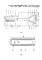
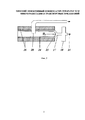
На фиг. 1 представлен общий вид системы охлаждения микроэлектронного оборудования с использованием предлагаемого конденсатора-сепаратора.In FIG. 1 shows a General view of the cooling system of microelectronic equipment using the proposed condenser-separator.
На фиг. 2 представлен поперечный разрез конденсатора.In FIG. 2 is a cross-sectional view of a capacitor.
На фиг. 3 представлен поперечный разрез сепаратора.In FIG. 3 is a cross-sectional view of a separator.
Где 1 - подложка, 2 - электронный компонент, 3 - конденсатор, 4 - сепаратор, 5 - мини- или микроканал испарителя, 6 - испаряющаяся пленка жидкости, 7 - канал для парогазовой смеси и неиспарившейся жидкости, 8 - резервуар газа, 9 - насос по газу, 10 - вход газа, 11 - резервуар жидкости, 12 - насос по жидкости, 13 - вход жидкости, 14 - конденсат, заполняющий углы канала конденсатора и сепаратора, 15 - мениск жидкости в конденсаторе с радиусом R1, 16 - система охлаждения конденсатора и сепаратора, 17 - капиллярный щелевой затвор сепаратора, 18 - полость для откачки конденсата, 19 - выход газа, 20 - трубка для сбора газа в сепараторе, 21 - выход жидкости, 22 - направление течения жидкости в сепараторе, 23 - мениск жидкости в сепараторе с радиусом R2, 24 - пленка жидкости в сепараторе и конденсаторе, 25 - боковые стенки конденсатора и сепаратора, 26 - торцевая стенка сепаратора.Where 1 is the substrate, 2 is the electronic component, 3 is the condenser, 4 is the separator, 5 is the mini- or microchannel of the evaporator, 6 is the evaporating film of liquid, 7 is the channel for the vapor-gas mixture and non-evaporated liquid, 8 is the gas reservoir, 9 is the pump for gas, 10 - gas inlet, 11 - liquid reservoir, 12 - liquid inlet, 14 - liquid inlet, condensate filling the corners of the condenser and separator channel, 15 - liquid meniscus in the condenser with radius R 1 , 16 - cooling system condenser and separator, 17 - capillary slotted shutter of the separator, 18 - cavity for pumping out condensate, 19 - gas outlet, 20 - tube for collecting gas in the separator, 21 - liquid outlet, 22 - direction of fluid flow in the separator, 23 - meniscus of liquid in the separator with a radius of R 2 , 24 - liquid film in the separator and condenser, 25 - side the walls of the condenser and separator, 26 - the end wall of the separator.
Устройство работает следующим образом.The device operates as follows.
Перед началом работы жидкость заполняет резервуар 11. Пар или парогазовая смесь равномерно распределяется по системе. Включают систему охлаждения 16, конденсатор начинает конденсировать и генерировать пленку жидкости 24, которая движется под действием капиллярных сил в направлении капиллярного щелевого затвора 17 сепаратора. Затем включают насос 12, который подает жидкость из резервуара 11 через вход 13 в мини- или микроканал 5. Резервуар 11 служит для более устойчивой работы насоса 12. Пленка жидкости 6 натекает на электронный компонент 2, расположенный на подложке 1, и охлаждает его. Включают насос 9, который подает газ из резервуара 8 через вход 10 в мини- или микроканал испарителя 5. В мини- или микроканале испарителя устанавливается стабильное расслоенное пленочное течение. Часть жидкости уходит по каналу 7 в конденсатор и под действием капиллярных сил полностью заполняет капиллярный щелевой затвор сепаратора 17. Подают нагрузку на электронный компонент 2. При этом основная часть жидкости превращается в пар и уходит по каналу 7 вместе с газом в конденсатор 3, где пар конденсируется. Пленка жидкости 24 движется в направлении капиллярного щелевого затвора сепаратора 17, попадает в полость для откачки конденсата в сепараторе 18 и далее через выход 21 попадает в резервуар 11. Далее жидкость перекачивается насосом 12 в мини- или микроканал испарителя. Парогазовая смесь движется вдоль канала конденсатора, обедняется паром за счет конденсации и забирается из конденсатора по трубке для сбора газа в сепараторе 20 и выход 19 в емкость газа 8. Далее газ перекачивается насосом 9 в микро- или мини-канал испарителя.Before starting work, the liquid fills the
Использование заявляемого изобретения позволяет обеспечить более интенсивную, более контролируемую и экономичную конденсацию пара, а следовательно, и более эффективную сепарацию газа и жидкости, за счет создания тонких пленок и капиллярных сил. Эффективность сепарации в значительной степени зависит от температуры поверхностей конденсатора 3 и сепаратора 4, а кроме того, длины конденсатора и скорости парогазовой смеси на входе в конденсатор и может быть оптимизирована.The use of the claimed invention allows for more intensive, more controlled and economical condensation of steam, and hence more efficient separation of gas and liquid, due to the creation of thin films and capillary forces. The separation efficiency largely depends on the surface temperature of the
Как правило, используют обычное водяное охлаждение конденсатора и сепаратора. Для очень точной регулировки мощности для охлаждения конденсатора в мини- и микросистемах могут использоваться Пельтье элементы с последующим их охлаждением водой или воздухом. В отдельных приложениях для охлаждения могут использоваться тепловые трубы (космические приложения) или по внутренним каналам конденсатора может прокачиваться охлажденный воздух (газ).Typically, conventional water cooling of the condenser and separator is used. For very precise power control for cooling the condenser in mini- and microsystems, Peltier elements can be used, followed by their cooling with water or air. In individual cooling applications, heat pipes (space applications) can be used, or cooled air (gas) can be pumped through the internal channels of the condenser.
Пленка жидкости в конденсаторе 24, а также конденсат, заполняющий углы канала конденсатора 14, увлекается частью несконденсировавшегося пара и газом и движется вдоль канала конденсатора. Конденсат, заполняющий углы канала конденсатора 14, может двигаться вдоль конденсатора также за счет капиллярных сил. Радиус мениска жидкости в сепараторе, R2 может быть на порядок меньше, чем радиус мениска жидкости в конденсаторе, R1, что создает перепад капиллярного давления в жидкости и обеспечивает транспорт конденсата в сторону сепаратора. Данный эффект, аналогичный капиллярному транспорту в тепловых трубах, будет снижать ширину жидкости заполняющей углы канала конденсатора и интенсифицировать теплообмен при конденсации.The liquid film in the
Устройство может работать в условиях нормальной гравитации и микрогравитации. В условиях микрогравитации ориентация устройства может быть произвольной. В условиях нормальной гравитации рекомендуется такое положение устройства, когда плоскость продольного сечения конденсатора-сепаратора перпендикулярна направлению вектора силы тяжести. При этом будет достигаться максимальное качество сепарации. Однако отклонения от указанного положения на 20-30 градусов практически не будут влиять на качество работы системы.The device can operate in normal gravity and microgravity. In microgravity conditions, the orientation of the device can be arbitrary. Under normal gravity conditions, it is recommended that the device position when the plane of the longitudinal section of the capacitor-separator is perpendicular to the direction of the gravity vector. In this case, maximum separation quality will be achieved. However, deviations from the indicated position by 20-30 degrees will practically not affect the quality of the system.
Представленный конденсатор-сепаратор может успешно применяться на транспортных средствах, пассажирских и транспортных самолетах. При тех же объемах конденсата, как и в прототипе, гидравлическое сопротивление предложенного конденсатора-сепаратора будет существенно ниже из-за прямой геометрии канала. Это, в свою очередь, приведет к снижению энергозатрат на прокачку жидкости и газа и повышению общей эффективности системы. Кроме того, предложенная конструкция конденсатора-сепаратора обладает существенно меньшими габаритами и весом по сравнению с прототипом.The presented condenser-separator can be successfully used on vehicles, passenger and transport aircraft. With the same volumes of condensate, as in the prototype, the hydraulic resistance of the proposed capacitor-separator will be significantly lower due to the direct geometry of the channel. This, in turn, will lead to lower energy costs for pumping liquid and gas and increase the overall efficiency of the system. In addition, the proposed design of the capacitor-separator has significantly smaller dimensions and weight compared to the prototype.
Claims (1)
Priority Applications (1)
| Application Number | Priority Date | Filing Date | Title |
|---|---|---|---|
| RU2016152541A RU2640887C1 (en) | 2016-12-30 | 2016-12-30 | Flat efficient condenser-separator for microgravitation and transport applications |
Applications Claiming Priority (1)
| Application Number | Priority Date | Filing Date | Title |
|---|---|---|---|
| RU2016152541A RU2640887C1 (en) | 2016-12-30 | 2016-12-30 | Flat efficient condenser-separator for microgravitation and transport applications |
Publications (1)
| Publication Number | Publication Date |
|---|---|
| RU2640887C1 true RU2640887C1 (en) | 2018-01-12 |
Family
ID=68235573
Family Applications (1)
| Application Number | Title | Priority Date | Filing Date |
|---|---|---|---|
| RU2016152541A RU2640887C1 (en) | 2016-12-30 | 2016-12-30 | Flat efficient condenser-separator for microgravitation and transport applications |
Country Status (1)
| Country | Link |
|---|---|
| RU (1) | RU2640887C1 (en) |
Cited By (1)
| Publication number | Priority date | Publication date | Assignee | Title |
|---|---|---|---|---|
| RU2816280C1 (en) * | 2023-10-25 | 2024-03-28 | Федеральное государственное бюджетное учреждение науки Институт теплофизики им. С.С. Кутателадзе Сибирского отделения Российской академии наук | Method of feeding microdroplets of liquid onto heated surface of solid body |
Citations (4)
| Publication number | Priority date | Publication date | Assignee | Title |
|---|---|---|---|---|
| JPS60225498A (en) * | 1984-04-06 | 1985-11-09 | インタ−ナショナル ビジネス マシ−ンズ コ−ポレ−ション | Evaporating cooler |
| US20080237845A1 (en) * | 2007-03-28 | 2008-10-02 | Jesse Jaejin Kim | Systems and methods for removing heat from flip-chip die |
| US20130248153A1 (en) * | 2010-12-07 | 2013-09-26 | Breville Pty Limited | Direct air impingment cooling of package structures |
| RU141207U1 (en) * | 2013-12-05 | 2014-05-27 | Федеральное государственное бюджетное учреждение науки Институт теплофизики Уральского отделения Российской академии наук (ИТФ УрО РАН) | HEAT PIPE CAPACITOR |
-
2016
- 2016-12-30 RU RU2016152541A patent/RU2640887C1/en active
Patent Citations (4)
| Publication number | Priority date | Publication date | Assignee | Title |
|---|---|---|---|---|
| JPS60225498A (en) * | 1984-04-06 | 1985-11-09 | インタ−ナショナル ビジネス マシ−ンズ コ−ポレ−ション | Evaporating cooler |
| US20080237845A1 (en) * | 2007-03-28 | 2008-10-02 | Jesse Jaejin Kim | Systems and methods for removing heat from flip-chip die |
| US20130248153A1 (en) * | 2010-12-07 | 2013-09-26 | Breville Pty Limited | Direct air impingment cooling of package structures |
| RU141207U1 (en) * | 2013-12-05 | 2014-05-27 | Федеральное государственное бюджетное учреждение науки Институт теплофизики Уральского отделения Российской академии наук (ИТФ УрО РАН) | HEAT PIPE CAPACITOR |
Cited By (1)
| Publication number | Priority date | Publication date | Assignee | Title |
|---|---|---|---|---|
| RU2816280C1 (en) * | 2023-10-25 | 2024-03-28 | Федеральное государственное бюджетное учреждение науки Институт теплофизики им. С.С. Кутателадзе Сибирского отделения Российской академии наук | Method of feeding microdroplets of liquid onto heated surface of solid body |
Similar Documents
| Publication | Publication Date | Title |
|---|---|---|
| Ma et al. | Experimental investigation of flow boiling heat transfer performance in zigzag microchannel heat sink for electronic cooling devices | |
| Wang et al. | Investigation of a spray cooling system with two nozzles for space application | |
| US4220195A (en) | Ion drag pumped heat pipe | |
| Peng et al. | Influence of groove orientation on dropwise condensation on hydrophobic and hierarchical superhydrophobic surfaces with microgroove arrays | |
| US8716689B2 (en) | Thermal diode device and methods | |
| CN108444325B (en) | A cooling device combining nanofilm and microchannels | |
| Wang et al. | Comparative study of the heating surface impact on porous-material-involved spray system for electronic cooling–an experimental approach | |
| US20170321936A1 (en) | Gas-liquid phase separator | |
| Alipanah et al. | Ultra-low pressure drop membrane-based heat sink with 1000 W/cm2 cooling capacity and 100% exit vapor quality | |
| RU2635720C2 (en) | Efficient vapour condenser for microgravity conditions | |
| RU2640887C1 (en) | Flat efficient condenser-separator for microgravitation and transport applications | |
| RU2614897C1 (en) | Condenser separator for two-component two-phase systems | |
| RU2640888C1 (en) | Intensive steam condenser with contrast and gradient wetting | |
| Barakhovskaia et al. | Stabilisation of condensate flow from curvilinear surfaces by means of porous media for space applications | |
| Cheng et al. | Spot cooling using electrowetting-controlled thin film heat transfer | |
| Sridhar et al. | Phase change cooling of spacecraft electronics: Terrestrial reference experiments prior to ISS microgravity experiments | |
| RU2816279C1 (en) | System for cooling electronic equipment with mixture of steam and non-condensed gas | |
| US10677501B2 (en) | Component and efficient plate and frame absorber | |
| Azarkish et al. | Experimental and numerical investigation of a shaped microchannel evaporator for a micro Rankine cycle application | |
| RU2781758C1 (en) | Evaporative-condensing gas-liquid cooling system for electronic equipment | |
| RU2807853C1 (en) | Two-phase single-component cooling system | |
| EP4585284A1 (en) | Gravitational vapour compressor device | |
| Chugunkov et al. | Heat transfer calculation under film and drop condensation on tube with heat intensifiers | |
| US20260125285A1 (en) | Gravitational vapour compressor device | |
| RU2755608C1 (en) | Method for cooling electronic equipment |
Legal Events
| Date | Code | Title | Description |
|---|---|---|---|
| QB4A | Licence on use of patent |
Free format text: LICENCE FORMERLY AGREED ON 20190515 Effective date: 20190515 |
|
| QA4A | Patent open for licensing |
Effective date: 20201224 |