RU2640509C1 - Device to apply electrolytic coatings on steel pipes - Google Patents
Device to apply electrolytic coatings on steel pipes Download PDFInfo
- Publication number
- RU2640509C1 RU2640509C1 RU2016125450A RU2016125450A RU2640509C1 RU 2640509 C1 RU2640509 C1 RU 2640509C1 RU 2016125450 A RU2016125450 A RU 2016125450A RU 2016125450 A RU2016125450 A RU 2016125450A RU 2640509 C1 RU2640509 C1 RU 2640509C1
- Authority
- RU
- Russia
- Prior art keywords
- electrolyte
- pipe
- capsule
- end portion
- anode
- Prior art date
Links
Images
Classifications
-
- C—CHEMISTRY; METALLURGY
- C25—ELECTROLYTIC OR ELECTROPHORETIC PROCESSES; APPARATUS THEREFOR
- C25D—PROCESSES FOR THE ELECTROLYTIC OR ELECTROPHORETIC PRODUCTION OF COATINGS; ELECTROFORMING; APPARATUS THEREFOR
- C25D5/00—Electroplating characterised by the process; Pretreatment or after-treatment of workpieces
- C25D5/02—Electroplating of selected surface areas
- C25D5/026—Electroplating of selected surface areas using locally applied jets of electrolyte
-
- C—CHEMISTRY; METALLURGY
- C25—ELECTROLYTIC OR ELECTROPHORETIC PROCESSES; APPARATUS THEREFOR
- C25D—PROCESSES FOR THE ELECTROLYTIC OR ELECTROPHORETIC PRODUCTION OF COATINGS; ELECTROFORMING; APPARATUS THEREFOR
- C25D17/00—Constructional parts, or assemblies thereof, of cells for electrolytic coating
- C25D17/004—Sealing devices
-
- C—CHEMISTRY; METALLURGY
- C25—ELECTROLYTIC OR ELECTROPHORETIC PROCESSES; APPARATUS THEREFOR
- C25D—PROCESSES FOR THE ELECTROLYTIC OR ELECTROPHORETIC PRODUCTION OF COATINGS; ELECTROFORMING; APPARATUS THEREFOR
- C25D17/00—Constructional parts, or assemblies thereof, of cells for electrolytic coating
- C25D17/02—Tanks; Installations therefor
-
- C—CHEMISTRY; METALLURGY
- C25—ELECTROLYTIC OR ELECTROPHORETIC PROCESSES; APPARATUS THEREFOR
- C25D—PROCESSES FOR THE ELECTROLYTIC OR ELECTROPHORETIC PRODUCTION OF COATINGS; ELECTROFORMING; APPARATUS THEREFOR
- C25D17/00—Constructional parts, or assemblies thereof, of cells for electrolytic coating
- C25D17/10—Electrodes, e.g. composition, counter electrode
- C25D17/12—Shape or form
-
- C—CHEMISTRY; METALLURGY
- C25—ELECTROLYTIC OR ELECTROPHORETIC PROCESSES; APPARATUS THEREFOR
- C25D—PROCESSES FOR THE ELECTROLYTIC OR ELECTROPHORETIC PRODUCTION OF COATINGS; ELECTROFORMING; APPARATUS THEREFOR
- C25D5/00—Electroplating characterised by the process; Pretreatment or after-treatment of workpieces
- C25D5/08—Electroplating with moving electrolyte e.g. jet electroplating
-
- C—CHEMISTRY; METALLURGY
- C25—ELECTROLYTIC OR ELECTROPHORETIC PROCESSES; APPARATUS THEREFOR
- C25D—PROCESSES FOR THE ELECTROLYTIC OR ELECTROPHORETIC PRODUCTION OF COATINGS; ELECTROFORMING; APPARATUS THEREFOR
- C25D7/00—Electroplating characterised by the article coated
- C25D7/04—Tubes; Rings; Hollow bodies
Landscapes
- Chemical & Material Sciences (AREA)
- Engineering & Computer Science (AREA)
- Chemical Kinetics & Catalysis (AREA)
- Electrochemistry (AREA)
- Materials Engineering (AREA)
- Metallurgy (AREA)
- Organic Chemistry (AREA)
- Electroplating Methods And Accessories (AREA)
Abstract
Description
ОБЛАСТЬ ТЕХНИКИ, К КОТОРОЙ ОТНОСИТСЯ ИЗОБРЕТЕНИЕFIELD OF THE INVENTION
[0001] Настоящее изобретение относится к устройству для нанесения электролитических покрытий на стальные трубы. Более конкретно, настоящее изобретение относится к устройству для нанесения электролитических покрытий на стальные трубы, предназначенному для нанесения электролитического покрытия на внутреннюю резьбу, выполненную на концевом участке стальной трубы в качестве элемента резьбового соединения.[0001] The present invention relates to a device for applying electrolytic coatings to steel pipes. More specifically, the present invention relates to a device for applying electrolytic coatings to steel pipes, intended for applying an electrolytic coating to an internal thread made at an end portion of a steel pipe as an element of a threaded joint.
УРОВЕНЬ ТЕХНИКИBACKGROUND
[0002] В нефтяных скважинах, скважинах для добычи природного газа и тому подобных (далее также совокупно называемых «нефтяными скважинами») для извлечения полезных ископаемых (например, нефти, природного газа и т.д.) применяются трубы нефтепромыслового сортамента. Трубы нефтепромыслового сортамента, которые представляют собой стальные трубы, конфигурированы последовательно связанными друг с другом, и для связывания используются резьбовые соединения.[0002] In oil wells, wells for the extraction of natural gas and the like (hereinafter also collectively referred to as “oil wells”), oilfield pipes are used to extract minerals (eg, oil, natural gas, etc.). Oilfield tubular pipes, which are steel pipes, are configured in series with each other and threaded connections are used for bonding.
[0003] Как правило, такие резьбовые соединения классифицируют на два типа: соединение муфтового типа и соединение интегрального типа. Резьбовое соединение муфтового типа составлено парой трубных изделий, которые должны быть соединены между собой, из которых одно представляет собой стальную трубу, которая является более длинной, и другое представляет собой муфту, которая является более короткой. В этом случае стальная труба снабжается наружной резьбой, сформированной на наружной окружной поверхности каждого концевого участка ее, и муфта снабжается внутренней резьбой, образованной на внутренней окружной поверхности каждого концевого участка ее. Наружную резьбу стальной трубы ввинчивают во внутреннюю резьбу муфты, создавая тем самым соединение между ними. Резьбовое соединение интегрального типа составлено парой стальных труб как трубных изделий, которые должны быть соединены между собой без использования отдельной муфты. В этом случае каждую стальную трубу снабжают наружной резьбой, сформированной на наружной окружной поверхности на одном из ее противолежащих концевых участков, и внутренней резьбой, образованной на внутренней окружной поверхности на другом ее конце. Наружную резьбу одной из стальных труб ввинчивают во внутреннюю резьбу другой из стальных труб, создавая тем самым соединение между ними.[0003] Typically, such threaded connections are classified into two types: coupling type coupling and integral type coupling. The threaded connection of the coupling type is composed of a pair of pipe products that must be interconnected, of which one is a steel pipe, which is longer, and the other is a coupling, which is shorter. In this case, the steel pipe is supplied with an external thread formed on the outer circumferential surface of each end portion thereof, and the coupling is provided with an internal thread formed on the inner circumferential surface of each end portion thereof. The external thread of the steel pipe is screwed into the internal thread of the coupling, thereby creating a connection between them. The threaded connection of the integral type is composed of a pair of steel pipes as tube products, which should be interconnected without using a separate coupling. In this case, each steel pipe is provided with an external thread formed on the outer circumferential surface at one of its opposite end portions, and an internal thread formed on the inner circumferential surface at its other end. The external thread of one of the steel pipes is screwed into the internal thread of the other of the steel pipes, thereby creating a connection between them.
[0004] В недавние годы, по соображениям улучшения технологичности изготовления труб нефтепромыслового сортамента, существует повышенная необходимость в применении резьбового соединения интегрального типа. Это обусловливается тем, что не требуется отдельная муфта.[0004] In recent years, for reasons of improving the manufacturability of the production of oilfield pipes, there is an increased need for the use of an integral type threaded joint. This is because a separate coupling is not required.
[0005] Когда наращивают стальные трубы, на наружную резьбу и на внутреннюю резьбу наносят консистентную смазку (смазку для герметизации). Назначение этого состоит в предотвращении фрикционной коррозии в резьбах, а также для повышения эффективности герметизации резьбового соединения. Обычно в качестве консистентной смазки широко применяют смазочные материалы, регламентированные стандартами API (Американским Институтом Нефти) (далее также называемыми «API-смазкой»). API-смазка содержит тяжелые металлы, такие как Pb (свинец), и проявляет высокую смазочную способность.[0005] When the steel pipes are extended, a grease (seal grease) is applied to the external thread and the internal thread. The purpose of this is to prevent frictional corrosion in the threads, as well as to increase the sealing efficiency of the threaded joint. Usually, lubricants are used as grease that is regulated by API standards (American Petroleum Institute) (hereinafter also referred to as “API grease”). API grease contains heavy metals such as Pb (lead) and exhibits high lubricity.
[0006] В недавние годы стало более строгим природоохранительное законодательство. Таким образом, было ограничено применение API-смазки, и возникла потребность в применении консистентной смазки, не содержащей тяжелых металлов (далее называемой также «зеленой смазкой»). Однако зеленая смазка имеет более низкую смазочную способность, чем API-смазка. Вследствие этого, в случае применения зеленой смазки, необходимо наносить электролитическое покрытие, такое как медное покрытие, на поверхность по меньшей мере одной из наружной резьбы и внутренней резьбы. Цель этого состоит в предотвращении истирания металла в резьбах, чтобы компенсировать недостаточную смазочную способность.[0006] In recent years, environmental legislation has become more stringent. Thus, the use of API grease was limited and a need arose for the use of a grease free of heavy metals (hereinafter also referred to as “green grease”). However, green grease has lower lubricity than API grease. Therefore, in the case of the use of green grease, it is necessary to apply an electrolytic coating, such as a copper coating, to the surface of at least one of the external thread and the internal thread. The purpose of this is to prevent abrasion of the metal in the threads in order to compensate for the lack of lubricity.
[0007] Когда наносят электролитическое покрытие на резьбовое соединение муфтового типа, покрытие наносят на внутреннюю резьбу муфты. Резьбовые соединения, имеющие электролитическое покрытие на внутренней резьбе муфты, проявляют высокую надежность. Благодаря высокой надежности, когда наносят электролитическое покрытие также на резьбовое соединение интегрального типа, в большей степени желательно, чтобы покрытие наносилось на его внутреннюю резьбу на концевом трубном участке стальной трубы.[0007] When an electrolytic coating is applied to a threaded coupling type, the coating is applied to the internal thread of the coupling. Threaded connections having an electrolytic coating on the internal thread of the coupling exhibit high reliability. Due to its high reliability, when an electrolytic coating is also applied to an integral type threaded joint, it is more desirable that the coating is applied to its internal thread at the end pipe section of the steel pipe.
[0008] Японская Патентная Публикация № S63-6637 (Патентный Документ 1) раскрывает устройство для нанесения электролитического покрытия на участок с наружной резьбой, сформированной на одном из концевых трубных участков стальной трубы, то есть, на наружной окружной поверхности концевого трубного участка стальной трубы.[0008] Japanese Patent Publication No. S63-6637 (Patent Document 1) discloses a device for applying an electrolytic coating to a portion with an external thread formed at one of the end pipe sections of the steel pipe, that is, on the outer circumferential surface of the end pipe section of the steel pipe.
СПИСОК ЦИТИРОВАННОЙ ЛИТЕРАТУРЫLITERATURE LITERATURE
ПАТЕНТНАЯ ЛИТЕРАТУРАPATENT LITERATURE
[0009] Патентный Документ 1: Японская Патентная Публикация № S63-6637[0009] Patent Document 1: Japanese Patent Publication No. S63-6637
СУЩНОСТЬ ИЗОБРЕТЕНИЯSUMMARY OF THE INVENTION
ТЕХНИЧЕСКАЯ ЗАДАЧАTECHNICAL PROBLEM
[0010] Во время процесса электролитического осаждения, как правило, пока формируется электролитически осаждаемый слой, образуются пузырьки водорода, кислорода или тому подобные. Когда электролитическое покрытие наносят на наружную резьбу, образованную на наружной окружной поверхности концевого участка трубы, как раскрыто в Патентном Документе 1, газовые пузырьки быстро уходят с поверхности наружной резьбы и всплывают. Таким образом, газовые пузырьки не создают проблемы. Однако, когда электролитическое покрытие наносят на внутреннюю резьбу, сформированную на внутренней окружной поверхности концевого участка трубы, газовые пузырьки удерживаются, в особенности на верхней части внутренней окружной поверхности концевого участка трубы. Области, где остаются газовые пузырьки, становятся непреднамеренно оголенными участками.[0010] During the electrolytic deposition process, as a rule, while an electrolytically deposited layer is formed, bubbles of hydrogen, oxygen or the like are formed. When an electrolytic coating is applied to an external thread formed on the outer circumferential surface of the end portion of the pipe, as disclosed in Patent Document 1, gas bubbles quickly leave the surface of the external thread and float. Thus, gas bubbles do not pose a problem. However, when the electrolytic coating is applied to the internal thread formed on the inner circumferential surface of the end portion of the pipe, gas bubbles are held, especially on the upper part of the inner circumferential surface of the end portion of the pipe. The areas where gas bubbles remain become unintentionally exposed areas.
[0011] Кроме того, как только процесс электролитического осаждения завершается, электролит должен быть немедленно удален из концевого участка трубы. Причина этого состоит в том, что развивается вызываемая электролитом коррозия и приводит к потускнению поверхности электролитически осаждаемого слоя. В этом отношении, при устройстве для нанесения электролитического покрытия, представленном в Патентном Документе 1, выгрузка израсходованного электролита из камеры занимает много времени, поскольку камера, в которой размещается концевой участок трубы и электролит, представляет собой полностью замкнутую систему. В результате этого, при допущении, что обрабатываемым объектом является стальная труба большого диаметра, если электролитическое покрытие наносят на внутреннюю резьбу на ее конце, в образованном на внутренней резьбе электролитически осаждаемом слое будет происходить потускнение.[0011] In addition, as soon as the electrolytic deposition process is completed, the electrolyte should be immediately removed from the end portion of the pipe. The reason for this is that corrosion caused by the electrolyte develops and leads to tarnishing of the surface of the electrolytically deposited layer. In this regard, with the electrolytic coating device presented in Patent Document 1, it takes a long time to unload the consumed electrolyte from the chamber, since the chamber in which the pipe end portion and the electrolyte are placed is a completely closed system. As a result of this, under the assumption that the object to be treated is a steel pipe of large diameter, if the electrolytic coating is applied to the internal thread at its end, tarnishing will occur in the electrolytically deposited layer formed on the internal thread.
[0012] Как правило, после выгрузки истощенного электролита, в камеру вводят воду вместо электролита для промывания концевого участка трубы водой. Если увеличивается количество отработанной воды от промывания водой, возрастают затраты на обработку отработанной воды. Таким образом, желательно сокращение количества отработанной воды.[0012] Typically, after the depleted electrolyte is discharged, water is introduced into the chamber instead of the electrolyte to flush the end portion of the pipe with water. If the amount of wastewater from washing with water increases, the cost of treating the wastewater increases. Thus, it is desirable to reduce the amount of waste water.
[0013] Задачей настоящего изобретения является создание устройства для нанесения электролитического покрытия на стальные трубы, имеющего следующие характеристики:[0013] An object of the present invention is to provide an apparatus for applying an electrolytic coating to steel pipes, having the following characteristics:
- предотвращение удерживания газовых пузырьков, образованных во время процесса электролитического осаждения, независимо от размера стальной трубы;- preventing the retention of gas bubbles formed during the electrolytic deposition process, regardless of the size of the steel pipe;
- немедленное удаление истощенного электролита после процесса электролитического осаждения; и- immediate removal of depleted electrolyte after the electrolytic deposition process; and
- сокращение количества отработанной воды.- reduction of waste water.
РЕШЕНИЕ ЗАДАЧИTHE SOLUTION OF THE PROBLEM
[0014] Устройство для нанесения электролитического покрытия на стальную трубу согласно одному варианту осуществления настоящего изобретения выполнено для нанесения электролитического покрытия на внутреннюю резьбу, выполненную на концевом участке стальной трубы.[0014] An apparatus for applying an electrolytic coating to a steel pipe according to one embodiment of the present invention is configured to apply an electrolytic coating to an internal thread formed at an end portion of a steel pipe.
Устройство для нанесения электролитического покрытия включает в себя: внутренний уплотнительный элемент; капсулу; выпуск; отверстие; цилиндрический нерастворимый анод и устройство для подачи электролита.A device for applying an electrolytic coating includes: an internal sealing element; capsule; release; hole; cylindrical insoluble anode and device for supplying electrolyte.
Внутренний уплотнительный элемент выполнен с возможностью расположения внутри стальной трубы и отделения внутренней части стальной трубы в месте, находящемся внутри в продольном направлении относительно области, на которой выполнена внутренняя резьба.The inner sealing element is arranged to be located inside the steel pipe and to separate the inner part of the steel pipe in a place located inside in the longitudinal direction relative to the area on which the internal thread is made.
Капсула выполнена с возможностью герметичного присоединения к концевому участку трубы.The capsule is made with the possibility of tight connection to the end section of the pipe.
Выпуск выполнен в капсуле для выпуска из него находящегося внутри капсулы электролита.The release is made in a capsule for the release of electrolyte inside the capsule.
Отверстие выполнено в капсуле для облегчения выпуска электролита, находящегося внутри капсулы.The hole is made in the capsule to facilitate the release of electrolyte inside the capsule.
Нерастворимый анод выполнен с возможностью размещения внутри концевого участка трубы, проходя, в то же время, через капсулу в герметичном сопряжении с капсулой.The insoluble anode is arranged to be placed inside the end portion of the pipe, passing, at the same time, through the capsule in a tight seal with the capsule.
Устройство для подачи электролита выполнено с возможностью подачи электролита внутрь концевого участка трубы, уплотненного внутренним уплотнительным элементом и капсулой.The electrolyte supply device is configured to supply electrolyte inside the end portion of the pipe, sealed with an internal sealing element and a capsule.
Устройство для подачи электролита включает в себя патрубок для подачи электролита и множество форсунок.An electrolyte supply device includes an electrolyte supply pipe and a plurality of nozzles.
Патрубок для подачи электролита проходит вдоль оси нерастворимого анода и выполнен с возможностью выступания из переднего конца нерастворимого анода внутрь концевого участка трубы. Форсунки присоединены к переднему концевому участку патрубка для подачи электролита для выпуска электролита между наружной окружной поверхностью нерастворимого анода и внутренней окружной поверхностью концевого участка трубы.The pipe for supplying electrolyte passes along the axis of the insoluble anode and is configured to protrude from the front end of the insoluble anode into the end portion of the pipe. The nozzles are attached to the front end portion of the electrolyte supply pipe to discharge electrolyte between the outer circumferential surface of the insoluble anode and the inner circumferential surface of the end portion of the pipe.
Нерастворимый анод имеет конфигурацию, не допускающую попадания выпускаемого из форсунок электролита в нерастворимый анод.The insoluble anode has a configuration that prevents the electrolyte discharged from the nozzles from entering the insoluble anode.
[0015] В вышеуказанном устройстве для нанесения электролитического покрытия отверстие предпочтительно размещено в верхней части капсулы и открыто в атмосферу, когда производится выпуск электролита после его истощения.[0015] In the above electrolytic coating device, a hole is preferably located in the upper part of the capsule and is exposed to the atmosphere when the electrolyte is released after it is depleted.
[0016] В вышеуказанном устройстве для нанесения электролитического покрытия конфигурация нерастворимого анода, которая не допускает попадания электролита, предпочтительно является такой, что на переднем конце нерастворимого анода предусмотрена крышка, и патрубок для подачи электролита проходит через крышку в герметичном сопряжении с крышкой.[0016] In the above electrolytic coating apparatus, the configuration of the insoluble anode that prevents the ingress of electrolyte is preferably such that a cap is provided at the front end of the insoluble anode and the electrolyte supply pipe passes through the cap in a sealed manner to the cap.
ПРЕИМУЩЕСТВЕННЫЕ РЕЗУЛЬТАТЫ ИЗОБРЕТЕНИЯBACKGROUND OF THE INVENTION
[0017] Устройство для нанесения электролитического покрытия стальных труб согласно настоящему изобретению имеет следующие существенные преимущества:[0017] A device for applying an electrolytic coating of steel pipes according to the present invention has the following significant advantages:
- способность предотвращать удерживание газовых пузырьков, образованных во время процесса электролитического осаждения, независимо от размера стальной трубы;- the ability to prevent the retention of gas bubbles formed during the electrolytic deposition process, regardless of the size of the steel pipe;
- способность немедленно удалять истощенный электролит после процесса электролитического осаждения; и- the ability to immediately remove depleted electrolyte after the electrolytic deposition process; and
- способность уменьшать количество отработанной воды.- the ability to reduce the amount of waste water.
КРАТКОЕ ОПИСАНИЕ ЧЕРТЕЖЕЙBRIEF DESCRIPTION OF THE DRAWINGS
[0018][0018]
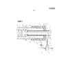
[ФИГ. 1] ФИГ. 1 представляет схематический вид в продольном разрезе, показывающий конфигурацию устройства для нанесения электролитического покрытия на стальные трубы, согласно одному варианту осуществления настоящего изобретения.[FIG. 1] FIG. 1 is a schematic longitudinal sectional view showing the configuration of an apparatus for applying an electrolytic coating to steel pipes, according to one embodiment of the present invention.
ОПИСАНИЕ ВАРИАНТОВ ОСУЩЕСТВЛЕНИЯ ИЗОБРЕТЕНИЯDESCRIPTION OF EMBODIMENTS OF THE INVENTION
[0019] Для достижения вышеуказанной цели, авторы настоящего изобретения провели обстоятельные исследования и в результате пришли к следующим выводам от (А) до (D).[0019] To achieve the above goal, the authors of the present invention conducted extensive studies and as a result came to the following conclusions (A) to (D).
[0020] (А) Если выпуск электролита между внутренней резьбой и анодом производится в форме спиральной струи из многочисленных форсунок, газовые пузырьки, которые образуются во время процесса электролитического осаждения, будут быстро выдуваться, и поэтому будет предотвращаться обусловленное удерживаемыми газовыми пузырьками образование оголенных участков.[0020] (A) If the electrolyte is discharged between the internal thread and the anode in the form of a spiral jet of multiple nozzles, the gas bubbles that form during the electrolytic deposition process will be quickly blown out, and therefore, the formation of exposed areas caused by the retained gas bubbles will be prevented.
[0021] (В) Чтобы обеспечить возможность срочного выпуска истощенного электролита, остающегося внутри концевого трубного участка стальной трубы после завершения процесса электролитического осаждения, может быть благоприятным создание конструкции для облегчения выпуска истощенного электролита. Посредством этого будет предотвращаться потускнение электролитически осаждаемого слоя, обусловленное коррозией под действием электролита.[0021] (B) In order to enable the urgent release of the depleted electrolyte remaining inside the end pipe portion of the steel pipe after completion of the electrolytic deposition process, it may be advantageous to provide a structure to facilitate the release of the depleted electrolyte. By this, tarnishing of the electrolytically deposited layer due to corrosion by the electrolyte will be prevented.
[0022] (С) Благодаря точно заданным местоположениям форсунок для выпуска электролита и направлениям выпуска, будет возможным стабильное формирование электролитически осаждаемого слоя независимо от размера стальной трубы. Более конкретно, когда обрабатываемым объектом является труба малого диаметра, будут предотвращаться появление оголенных участков и потускнение поверхности. Когда обрабатываемый объект представляет собой трубу большого диаметра, будет предотвращаться увеличение количества отработанной воды. Как используемый здесь, термин «труба малого диаметра» имеет отношение к трубе, имеющей наружный диаметр 4 дюйма (101,6 мм) или менее, термин «труба среднего диаметра» имеет отношение к трубе, имеющей наружный диаметр в диапазоне от более 4 дюймов до 9 дюймов (101,6-228,6 мм) или менее, и термин «труба большого диаметра» имеет отношение к трубе, имеющей наружный диаметр свыше 9 дюймов (228,6 мм).[0022] (C) Due to the precisely specified locations of the nozzles for the release of electrolyte and the directions of release, it will be possible to stably form an electrolytically deposited layer regardless of the size of the steel pipe. More specifically, when the object to be treated is a pipe of small diameter, the appearance of exposed areas and surface tarnishing will be prevented. When the treated object is a large diameter pipe, an increase in the amount of waste water will be prevented. As used here, the term "small diameter pipe" refers to a pipe having an outer diameter of 4 inches (101.6 mm) or less, the term "medium diameter pipe" refers to a pipe having an outer diameter in the range from more than 4 inches to 9 inches (101.6-228.6 mm) or less, and the term "large diameter pipe" refers to a pipe having an outer diameter of more than 9 inches (228.6 mm).
[0023] (D) Благодаря точному определению формы нерастворимого анода и формы устройства для подачи электролита будет возможным уменьшение количества отработанной воды, в том числе электролита.[0023] (D) By accurately determining the shape of the insoluble anode and the shape of the electrolyte supply device, it will be possible to reduce the amount of waste water, including the electrolyte.
[0024] На основе вышеуказанных выводов было создано устройство для нанесения электролитического покрытия согласно настоящему изобретению. Далее со ссылкой на чертежи будут описаны варианты исполнения устройства для нанесения электролитического покрытия согласно настоящему изобретению.[0024] Based on the above findings, an apparatus for applying an electrolytic coating according to the present invention was created. Next, with reference to the drawings, embodiments of an electrolytic coating device according to the present invention will be described.
[0025] ФИГ. 1 представляет схематический вид в продольном разрезе, показывающий конфигурацию устройства для нанесения электролитического покрытия на стальные трубы, согласно одному варианту осуществления настоящего изобретения. Как показано в ФИГ. 1, устройство 1 для нанесения электролитического покрытия представляет собой устройство, предназначенное для нанесения электролитического покрытия на внутреннюю резьбу 20b стальной трубы 20.FIG. 1 is a schematic longitudinal sectional view showing the configuration of an apparatus for applying an electrolytic coating to steel pipes, according to one embodiment of the present invention. As shown in FIG. 1, the electrolytic coating device 1 is a device for applying an electrolytic coating to an
[0026] Внутренняя резьба 20b сформирована на внутренней окружной поверхности одного из концевых трубных участков 20а стальной трубы 20. ФИГ. 1 показывает один вариант исполнения, в котором стальная труба 20 позиционирована в основном горизонтально. В альтернативном варианте, стальная труба 20 может быть размещена наклонно так, что концевой участок на стороне устройства 1 для нанесения электролитического покрытия находится слегка ниже, чем противоположный концевой участок. Позиционирование стальной трубы 20 наклонным образом, как было описано выше, является благоприятным в отношении предотвращения утечки электролита, находящегося внутри стальной трубы 20, в область, противоположную устройству 1 для нанесения электролитического покрытия, и уменьшения остающегося в концевом участке 20а трубы электролита, когда электролит выпускается наружу. В нижеследующем описании, в порядке примера, стальная труба 20 представляет собой бесшовную трубу нефтепромыслового сортамента, имеющую большую длину, конфигурированную для соединения посредством резьбового соединения интегрального типа.[0026] An
[0027] Устройство 1 для нанесения электролитического покрытия включает внутренний уплотнительный элемент 2, капсулу 3, нерастворимый анод 4 и устройство 5 для подачи электролита.[0027] The electrolytic coating device 1 includes an
[0028] [ВНУТРЕННИЙ УПЛОТНИТЕЛЬНЫЙ ЭЛЕМЕНТ][0028] [INTERNAL SEALING ELEMENT]
Внутренний уплотнительный элемент 2 вставлен внутрь стальной трубы 20 и размещен в предварительно заданном местоположении 20с обращенным внутрь по продольному направлению (горизонтальному направлению в ФИГ. 1) к области, на которой сформирована внутренняя резьба 20b. Внутренний уплотнительный элемент 2 находится в контакте со всем периметром внутренней окружной поверхности стальной трубы 20 и отделяет внутренность стальной трубы 20 в предварительно определенном месте 20с. Тем самым внутренность концевого участка 20а трубы герметично уплотнена изнутри внутренним уплотнительным элементом 2. Предварительно определенное место 20с, как здесь называемое, не является конкретно ограниченным в той мере, насколько оно обращено внутрь по продольному направлению к области, на которой сформирована внутренняя резьба 20b стальной трубы 20.The
[0029] Внутренний уплотнительный элемент 2 может иметь любую конфигурацию, пока он может отделять внутренность стальной трубы 20 и уплотнять изнутри внутренность ее концевого трубного участка 20а. Одним примером внутреннего уплотнительного элемента 2 является заглушка HEXA (от фирмы Mitsubishi Rubber Co., Ltd.), которая предназначена для применения при заглушении труб в трубопроводных работах на промышленных технологических установках для обработки нефти, газов, химических веществ и т.д. Заглушка HEXA включает резиновое кольцо, имеющее С-образное поперечное сечение, и пару плоских пластин, которые прочно удерживают резиновое кольцо между ними. Резиновое кольцо расширяется в диаметре, плотно удерживаясь между парой плоских пластин. Это приводит резиновое кольцо в контакт с внутренней окружной поверхностью трубы по всему ее периметру, герметизируя тем самым внутренность трубы вместе с плоскими пластинами.[0029] The
[0030] [КАПСУЛА][0030] [CAPSULE]
Капсула 3 имеет цилиндрический корпус 3а капсулы, имеющий закрытую торцевую поверхность. Корпус 3а капсулы присоединен к концевому трубному участку 20а стальной трубы 20. Более конкретно, корпус 3а капсулы находится в беззазорном сопряжении с наружной окружной поверхностью концевого участка 20а трубы и в плотном контакте с торцевой поверхностью концевого участка 20а трубы. Этим путем капсула 3 снаружи уплотняет внутренность концевого трубного участка 20а стальной трубы 20, причем корпус 3а капсулы присоединяется к концевому трубному участку 20а стальной трубы 20 в беззазорном сопряжении. Короче говоря, внутренность концевого участка 20а трубы герметизируется внутренним уплотнительным элементом 2 и капсулой 3.The capsule 3 has a
[0031] Корпус 3а капсулы снабжен выпуском 3с и отверстием 3b. Выпуск 3с главным образом предназначен для выпуска истощенного электролита после завершения процесса электролитического осаждения. В дополнение, выпуск 3с предназначен для непрерывного выведения и сбора электролита внутри корпуса 3а капсулы во время процесса электролитического осаждения и подачи собранного электролита на область внутри корпуса 3а капсулы из устройства 5 для подачи электролита. Кроме того, выпуск 3с предназначен для выпуска отработанной воды после промывания водой, которое выполняется после выпуска электролита. Выпуск 3с размещен на более низком уровне по высоте, нежели внутренняя окружная поверхность концевого трубного участка 20а стальной трубы 20.[0031] The
[0032] К выпуску 3с присоединен выпускной патрубок 7. Выпускной патрубок 7 на одном его конце открыт в растворный резервуар 9 для хранения электролита. Выпускной патрубок 7 оснащен клапаном 8 с возможностью выбора между пропускными каналами для выведения электролита (например, трехходовым клапаном). К выпускному клапану 8 присоединен патрубок 12 для отработанной воды. Патрубок 12 для отработанной воды на одном его конце открыт во внешний резервуар для отработанной воды (не показан).[0032] An
[0033] При проведении процесса электролитического осаждения с помощью выпускного клапана 8 открывается проток, ведущий к растворному резервуару 9. Тем самым электролит внутри корпуса 3а капсулы может непрерывно собираться и рециркулировать. Подобным образом, когда происходит выпуск истощенного электролита после завершения процесса электролитического осаждения, открывается проток, ведущий к растворному резервуару 9. Тем самым электролит внутри корпуса 3а капсулы может быть собран в растворном резервуаре 9. При проведении промывания водой после выпуска электролита, через выпускной клапан 8 открывается проток, ведущий к патрубку 12 для отработанной воды. Тем самым отработанная вода внутри корпуса 3а капсулы может быть выведена наружу в резервуар для отработанной воды.[0033] When the electrolytic deposition process is carried out using the
[0034] Отверстие 3b предусматривается для облегчения выпуска истощенного электролита. Местоположение отверстия 3b не является конкретно ограниченным в той мере, пока оно может облегчать выпуск электролита. Например, как показано в ФИГ. 1, отверстие 3b размещено на верхней части корпуса 3а капсулы. Отверстие 3b предпочтительно размещают на более высоком уровне по высоте, чем внутренняя окружная поверхности концевого трубного участка 20а стальной трубы 20.[0034] An
[0035] Конфигурация может быть такой, что к отверстию 3b присоединяют электромагнитный клапан (не показан), чтобы отверстие 3b можно было открывать и закрывать с помощью электромагнитного клапана. Когда используют эту конфигурацию, электромагнитный клапан открывается после завершения процесса электролитического осаждения так, что отверстие 3b открывается в атмосферу. Это обеспечивает возможность действия атмосферного давления на электролит внутри корпуса 3а капсулы, облегчая тем самым выведение электролита из выпуска 3с.[0035] The configuration may be such that a solenoid valve (not shown) is connected to the
[0036] В альтернативном варианте, конфигурация может быть такой, что к отверстию 3b присоединяют проходящий вверх шланг (не показан). В этом случае, во время процесса электролитического осаждения давление электролита, прилагаемое на область внутри корпуса 3а капсулы описываемым ниже насосом 10 устройства 5 для подачи электролита, и вес электролита, введенного в шланг, уравновешиваются так, что предотвращается выдавливание электролита наружу из корпуса 3а капсулы.[0036] Alternatively, the configuration may be such that an upwardly extending hose (not shown) is connected to the
[0037] Кроме того, конфигурация может быть такой, что к шлангу присоединяют компрессор (не показан). Когда применяют эту конфигурацию, то после завершения процесса электролитического осаждения на область внутри корпуса 3а капсулы из отверстия 3b компрессором подается сжатый воздух. Таким образом, на электролит внутри корпуса 3а капсулы действует высокое давление, облегчая тем самым выведение электролита из выпуска 3с.[0037] Furthermore, the configuration may be such that a compressor (not shown) is connected to the hose. When this configuration is applied, after completion of the electrolytic deposition process, compressed air is supplied to the area inside the
[0038] Как было описано выше, созданное в корпусе 3а капсулы отверстие 3b облегчает выпуск электролита из выпуска 3с. Таким образом, выпуск истощенного электролита выполняется быстро и поэтому не возникает потускнение на поверхности электролитически осаждаемого слоя, сформированного на внутренней резьбе 20b.[0038] As described above, the
[0039] [НЕРАСТВОРИМЫЙ АНОД][0039] [Insoluble Anode]
Нерастворимый анод 4 (далее также называемый просто «анодом» 4) представляет собой цилиндрический электрод (анод) для нанесения электролитического покрытия на внутреннюю резьбу 20b. Нерастворимый анод 4 пропускается через торцевую поверхность корпуса 3а капсулы и продолжается до внутренней части концевого трубного участка 20а стальной трубы 20. Таким образом, анод 4 размещают вблизи внутренней резьбы 20b. Корпус 3а капсулы и анод 4, проходящий через корпус 3а капсулы, герметизированы уплотнительным кольцом или тому подобным. Анод 4 поддерживается корпусом 3а капсулы.The insoluble anode 4 (hereinafter also referred to simply as the “anode” 4) is a cylindrical electrode (anode) for applying an electrolytic coating to the
[0040] В качестве анода 4 используют цилиндрическую деталь, выполненную из титановой пластины, покрытой оксидом иридия, пластины из нержавеющей стали или тому подобной.[0040] As the anode 4, a cylindrical part made of a titanium plate coated with iridium oxide, a stainless steel plate or the like is used.
[0041] К аноду 4 присоединен электропроводный стержень 6. Примеры электропроводного стержня 6 включают титановый стержень, стержень из нержавеющей стали и тому подобные.[0041] An electrical conductive rod 6 is attached to the anode 4. Examples of the electrical conductive rod 6 include a titanium rod, a stainless steel rod, and the like.
[0042] Разность потенциалов прилагают через электролит между анодом 4 и концевым трубным участком 20а стальной трубы 20, окружающим анод 4. Тем самым на внутреннюю резьбу 20b стальной трубы 20 наносится электролитическое покрытие.[0042] A potential difference is applied through an electrolyte between the anode 4 and the
[0043] Как было описано выше, анод 4 имеет цилиндрическую форму и является полым внутри. Таким образом, анод 4 имеет малый вес и прост в обращении с ним. Кроме того, тем самым может быть снижена стоимость материала. Следует отметить, что анод 4 имеет конфигурацию, которая не допускает попадания в него электролита, выпускаемого из описываемых ниже форсунок 5b. Благодаря этому ускоряется выведение электролита после завершения процесса электролитического осаждения. В результате этого дополнительно предотвращается потускнение поверхности электролитически осаждаемого слоя, сформированного на внутренней резьбе 20b.[0043] As described above, the anode 4 has a cylindrical shape and is hollow inside. Thus, the anode 4 is lightweight and easy to handle. In addition, thereby the cost of the material can be reduced. It should be noted that the anode 4 has a configuration that prevents ingress of electrolyte discharged from the
[0044] Конфигурация, которая не позволяет электролиту попадать в анод 4, не является конкретно ограниченной, но, например, может быть применена следующая конструкция. На переднем конце анода 4, расположенного внутри концевого участка 20а трубы, размещают крышку 4а, имеющую тороидальную форму. Крышка 4а присоединена к аноду 4 сваркой или тому подобным путем, и отделяет внутренность анода 4 от его наружного окружения. Следует отметить, что сквозь крышку 4а проходит описываемый ниже патрубок 5а для подачи электролита. Сопряжение крышки 4а и пропущенного сквозь крышку 4а патрубка 5а для подачи электролита герметизировано уплотнительным кольцом или тому подобным.[0044] A configuration that prevents the electrolyte from entering the anode 4 is not particularly limited, but, for example, the following design may be applied. At the front end of the anode 4 located inside the
[0045] [УСТРОЙСТВО ДЛЯ ПОДАЧИ ЭЛЕКТРОЛИТА][0045] [ELECTROLYTE SUPPLY DEVICE]
Устройство 5 для подачи электролита подает электролит внутрь концевого участка 20а трубы, герметизированного внутренним уплотнительным элементом 2 и капсулой 3. Более конкретно, устройство 5 для подачи электролита включает патрубок 5а для подачи электролита и многочисленные форсунки 5b. Патрубок 5а для подачи электролита проходит вдоль оси анода 4 и выступает из переднего конца (крышки 4а в устройстве 1 для нанесения электролитического покрытия, показанном в ФИГ. 1) анода 4 внутрь концевого участка 20а трубы. Форсунки 5b присоединены к переднему концевому участку патрубка 5а для подачи электролита, выступающему из переднего конца анода 4. Задний концевой участок 5аа патрубка 5а для подачи электролита проходит через боковую часть заднего концевого участка 4b анода 4, выступающего наружу из корпуса 3а капсулы, и выходит наружу. Патрубок 5а для подачи электролита поддерживается корпусом 3а капсулы через анод 4.The electrolyte supply device 5 supplies the electrolyte inside the
[0046] К заднему концевому участку 5аа патрубка 5а для подачи электролита присоединен главный трубопровод 11 от растворного резервуара 9 для хранения электролита. Главный трубопровод 11 оснащен насосом 10 для нагнетания электролита в патрубок 5а для подачи электролита. Кроме того, главный трубопровод 11 снабжен клапаном 13 между насосом 10 и растворным резервуаром 9, с возможностью выбора между пропускными каналами для подачи электролита (например, трехходовым клапаном). К питающему клапану 13 присоединен водопровод 15 от водяного бака 14 для хранения воды для промывания водой.[0046] To the rear end portion 5aa of the
[0047] При проведении процесса электролитического осаждения через питающий клапан 13 открывается проток от растворного резервуара 9 к патрубку 5а для подачи электролита. Кроме того, приводится в действие насос 10. Этим обеспечивается подача электролита на область внутри корпуса 3а капсулы через патрубок 5а для подачи электролита. Когда после завершения процесса электролитического осаждения проводится выпуск истощенного электролита, работа насоса 10 останавливается. Таким образом, прекращается подача электролита на область внутри корпуса 3а капсулы, и электролит внутри корпуса 3а капсулы собирается в растворный резервуар 9. Когда после выпуска электролита выполняется промывание водой, через питающий клапан 13 открывается проток от водяного бака 14 к патрубку 5а для подачи электролита. Кроме того, приводится в действие насос 10. Это обеспечивает введение воды на область внутри корпуса 3а капсулы через патрубок 5а для подачи электролита, чтобы промывать водой концевой трубный участок 20а стальной трубы 20.[0047] When carrying out the electrolytic deposition process through the
[0048] Форсунки 5b позиционированы обращенными внутрь к переднему концу анода 4 по продольному направлению стальной трубы 20, и наконечник 5ba каждой форсунки направлен в сторону наружной части концевого участка 20а трубы в продольном направлении. Электролит, нагнетаемый в патрубок 5а для подачи электролита, выпускается из форсунок 5b в форме спиральной струи между наружной окружной поверхностью анода 4 и внутренней окружной поверхностью концевого участка 20а трубы (точности ради, внутренней резьбой 20b, сформированной на концевом участке 20а трубы). Число форсунок 5b не является конкретно ограниченным, но предпочтительно составляет две или более и более предпочтительно три или более.[0048] The
[0049] Что касается местоположения форсунок, одна простая конфигурация является такой, что форсунки размещают на торцевой поверхности корпуса 3а капсулы, то есть, форсунки располагают снаружи концевого участка 20а трубы по продольному направлению. Однако эта конфигурация не используется в устройстве для нанесения электролитического покрытия согласно настоящему изобретению по следующим соображениям.[0049] Regarding the location of the nozzles, one simple configuration is that the nozzles are placed on the end surface of the
[0050] Размер стальной трубы 20 варьирует в широких пределах, например, от около 60 мм до около 410 мм наружного диаметра. Когда стальная труба 20 представляет собой трубу малого диаметра, применяется цилиндрический анод 4 с маленьким диаметром. В этом случае, если форсунки позиционированы снаружи концевого участка 20а трубы, на струи электролита из форсунок сильно влияют возвратные потоки электролита изнутри концевого участка 20а трубы в сторону выпуска 3с, расположенного снаружи концевого участка 20а трубы. Вследствие этого нельзя получить достаточной силы струи, вытекающие из форсунок. В результате этого может происходить удерживание газовых пузырьков и могут возникать оголенные участки.[0050] The size of the
[0051] С другой стороны, когда стальная труба 20 представляет собой трубу большого диаметра, то даже если форсунки позиционированы снаружи концевого участка 20а трубы, можно получить потоки струй электролита достаточной силы, пока обеспечивается мощность насоса 10, так что удерживание газовых пузырьков не происходит, и оголенные участки не возникают. Однако в этом случае, если форсунки размещены снаружи концевого участка 20а трубы, выпуск электролита становится длительным по времени, когда проводится выведение истощенного электролита после завершения процесса электролитического осаждения, и это приводит к потускнению поверхности электролитически осаждаемого слоя, сформированного на внутренней резьбе 20b. Кроме того, когда выполняют промывание водой после выпуска электролита, количество отработанной воды после промывания водой возрастает, если форсунки позиционированы снаружи концевого участка 20а трубы, и это имеет результатом увеличение затрат на обработку отработанной воды.[0051] On the other hand, when the
[0052] Более конкретно, когда стальная труба 20 представляет собой трубу малого диаметра с наружным диаметром 2-7/8 дюйма (73,03 мм), то если наконечники форсунок размещены снаружи концевого участка 20а трубы, невозможно получить равномерные и достаточно сильные потоки струй, и это приводит к удерживанию газовых пузырьков и возникновению оголенных участков. Напротив, когда наконечники 5ba форсунок 5b позиционированы внутрь к переднему концу анода 4 по продольному направлению стальной трубы 20, как в описанном выше данном варианте исполнения, не возникают ни оголенные участки, ни потускнение поверхности. Это происходит потому, что формируются равномерные и достаточно сильные потоки струй между внутренней резьбой 20b и анодом 4, и поэтому не происходит удерживание электролита. Наружный диаметр стальной трубы 20 (2-7/8 дюйма (73,03 мм)), как представленный здесь, является номинальным наружным диаметром, регламентированным стандартами API, и та же система обозначений применяется ниже.[0052] More specifically, when the
[0053] Кроме того, когда стальная труба 20 представляет собой трубу среднего диаметра 7-5/8 дюйма (193,68 мм) в наружном диаметре, оголенные участки или потускнение редко возникают, даже когда наконечники форсунок позиционированы снаружи концевого участка 20а трубы. Однако увеличивается количество отработанной воды, приводя к возрастанию затрат на обработку отработанной воды.[0053] Furthermore, when the
[0054] Кода стальная труба 20 представляет собой трубу большого диаметра 13-3/8 дюйма (339,73 мм) в наружном диаметре, можно получить потоки струй достаточной силы, даже когда наконечники форсунок позиционированы снаружи концевого участка 20а трубы, и поэтому оголенные участки вследствие удерживания газовых пузырьков не образуются. Однако занимает много времени выпуск большого объема электролита, и поэтому есть вероятность появления потускнения поверхности. Напротив, когда форсунки 5b позиционированы обращенными внутрь к переднему концу анода 4 по продольному направлению стальной трубы 20, как в описанном выше настоящем варианте исполнения, объем электролита действительно сокращается, и это имеет результатом быстрое выведение электролита. Таким образом, потускнение поверхности не происходит. Более того, количество отработанной воды уменьшается почти до одной десятой части, что приводит к значительному сокращению затрат на обработку отработанной воды.[0054]
[0055] По вышеуказанным соображениям, устройство 1 для нанесения электролитического покрытия конфигурировано так, что форсунки 5b и их наконечники 5ba размещены обращенными внутрь к переднему концу анода 4 по продольному направлению стальной трубы 20, и наконечник 5ba каждой форсунки направлен в сторону наружной части концевого участка 20а трубы по продольному направлению.[0055] For the above considerations, the electrolytic coating device 1 is configured so that the
[0056] Наконечники 5ba форсунок 5b предпочтительно позиционируют в радиальном направлении стальной трубы 20, между внутренней резьбой 20b и анодом 4.[0056] The tips 5ba of the
[0057] Показанные в ФИГ. 1 наконечники 5ba форсунок 5b имеют прямолинейную форму, ориентированную в сторону внутренней резьбы 20b. В альтернативном варианте, чтобы повысить равномерность потоков струй, которые формируются между внутренней резьбой 20b и анодом 4, наконечники 5ba форсунок 5b могут быть наклонены в сторону наружной поверхности стальной трубы 20 в радиальном направлении, например, в зависимости от диаметра стальной трубы 20, размера внутренней резьбы 20b, или тому подобного. Кроме того, когда выполняется электролитическое осаждение на стальных трубах 20, имеющих различные размеры, предпочтительно, чтобы направление, по которому электролит выпускается из форсунок 5b, надлежащим образом модифицировался для каждой из стальных труб 20 в зависимости от ее диаметра, размера ее внутренней резьбы 20b, или тому подобного.[0057] Shown in FIG. 1, the tips 5ba of the
ПРИМЕРЫEXAMPLES
[0058] Для подтверждения преимуществ устройства для нанесения электролитического покрытия согласно настоящему варианту исполнения, было проведено следующее испытание с использованием устройства для нанесения электролитического покрытия, показанного на ФИГ. 1. В качестве электролитов были приготовлены обезжиривающий раствор (гидроксид натрия: 50 г/л), Ni-ванна «затяжки» (хлорид никеля: 250 г/л, соляная кислота: 80 г/л), и электролитическая Cu-ванна (сульфат меди: 250 г/л, серная кислота: 110 г/л). Затем, с использованием ванн в этом порядке на внутреннюю резьбу на концевом трубном участке стальной трубы было нанесено электролитическое покрытие (медное покрытие). Условия процесса для каждой стадии с использованием каждой ванны были показаны ниже в Таблице 1.[0058] In order to confirm the advantages of the electrolytic coating device according to the present embodiment, the following test was carried out using the electrolytic coating device shown in FIG. 1. A degreasing solution (sodium hydroxide: 50 g / l), a “puff” Ni-bath (nickel chloride: 250 g / l, hydrochloric acid: 80 g / l), and an electrolytic Cu bath (sulfate) were prepared as electrolytes. copper: 250 g / l, sulfuric acid: 110 g / l). Then, using bathtubs in this order, an electrolytic coating (copper coating) was applied to the internal thread at the end pipe portion of the steel pipe. The process conditions for each stage using each bath were shown below in Table 1.
[0059] [Таблица 1][0059] [Table 1]
[0060] В этом испытании, с использованием стальных труб, имеющих различные наружные диаметры, местоположение форсунок варьировали между положениями, обращенными внутрь к переднему концу анода, и положениями снаружи концевого участка трубы. Кроме того, варьировали присутствие или отсутствие отверстия в корпусе капсулы. Оценки были сделаны по наличию оголенных участков, по потускнению поверхности электролитически осаждаемого слоя и по количеству отработанной воды после промывания водой, которое выполняют между стадиями. Таблица 2 ниже показывает условия испытаний и полученные результаты. Значения условных знаков в секциях параметров оценки (оголенные участки и потускнению поверхности электролитически осаждаемого слоя) Таблицы 2 являются следующими.[0060] In this test, using steel pipes having different outer diameters, the location of the nozzles was varied between the positions facing inward to the front end of the anode and the positions outside the end portion of the pipe. In addition, the presence or absence of a hole in the capsule body was varied. Estimates were made for the presence of exposed areas, for the tarnishing of the surface of the electrolytically deposited layer, and for the amount of wastewater after washing with water, which is performed between stages. Table 2 below shows the test conditions and the results obtained. The values of the symbols in the sections of the evaluation parameters (exposed areas and surface tarnishing of the electrolytically deposited layer) of Table 2 are as follows.
[ОГОЛЕННЫЕ УЧАСТКИ][NARROWED SITES]
- О (превосходно): оголенные участки не наблюдались.- O (excellent): no exposed areas were observed.
- ✕ (плохо): наблюдались многие оголенные участки.- ✕ (bad): many exposed areas were observed.
[Потускнение поверхности электролитически осаждаемого слоя][Tarnishing of the surface of the electrolytically deposited layer]
- О (превосходно): потускнение не наблюдалось.- Oh (excellent): no tarnishing was observed.
- Δ (хорошо): наблюдалось незначительное потускнение.- Δ (good): slight tarnishing was observed.
- ✕ (плохо): наблюдалось потускнение.- ✕ (bad): tarnishing was observed.
[0061] [Таблица 2][0061] [Table 2]
[0062] Результаты в Таблице 2 демонстрируют следующее. Как видно в Сравнительных Примерах 1 и 2, когда обрабатываемым объектом была труба малого диаметра и форсунки были позиционированы снаружи концевого участка трубы, равномерные и достаточно сильные потоки струй не получались, и поэтому образовывались оголенные участки вследствие удерживания газовых пузырьков. В дополнение, как видно в Сравнительном Примере 2, даже когда корпус капсулы имел отверстие, на поверхности электролитически осаждаемого слоя возникало некоторое потускнение.[0062] The results in Table 2 demonstrate the following. As can be seen in Comparative Examples 1 and 2, when the pipe being processed was a small-diameter pipe and the nozzles were positioned outside the end section of the pipe, uniform and sufficiently strong stream flows were not obtained, and therefore, bare sections were formed due to the retention of gas bubbles. In addition, as can be seen in Comparative Example 2, even when the capsule body had an opening, some tarnishing occurred on the surface of the electrolytically deposited layer.
[0063] Напротив, как видно в Примере 1, когда обрабатываемым объектом являлась труба малого диаметра и форсунки были позиционированы внутрь к переднему концу анода, не наблюдались ни оголенные участки, ни потускнение поверхности. Это происходит благодаря тому обстоятельству, что между внутренней резьбой и анодом были сформированы равномерные и достаточной силы потоки струй, и поэтому задерживание электролита не происходило.[0063] On the contrary, as can be seen in Example 1, when the workpiece was a small-diameter pipe and the nozzles were positioned inward to the front end of the anode, neither exposed areas nor surface fading were observed. This is due to the fact that between the internal thread and the anode, uniform and sufficient force jets were formed, and therefore electrolyte retention did not occur.
[0064] Как видно в Сравнительном Примере 3, когда обрабатываемым объектом была труба среднего диаметра и форсунки были позиционированы снаружи концевого участка трубы, оголенные участки не возникали. Однако происходило некоторое потускнение поверхности, и значительно увеличивалось количество отработанной воды.[0064] As can be seen in Comparative Example 3, when the object to be treated was a pipe of medium diameter and the nozzles were positioned outside the end section of the pipe, bare sections did not occur. However, some surface fading occurred, and the amount of waste water increased significantly.
[0065] Напротив, как видно в Примере 2, когда обрабатываемым объектом являлась труба среднего диаметра и форсунки были позиционированы внутрь к переднему концу анода, количество отработанной воды сокращалось примерно до одной трети от количества в Сравнительном Примере 3.[0065] On the contrary, as can be seen in Example 2, when the object to be treated was a medium diameter pipe and the nozzles were positioned inward to the front end of the anode, the amount of waste water was reduced to about one third of the amount in Comparative Example 3.
[0066] Кроме того, как видно в Сравнительном Примере 4, когда обрабатываемым объектом была труба большого диаметра и форсунки были позиционированы снаружи концевого участка трубы, оголенные участки вследствие удерживания газовых пузырьков не возникали, так как были получены потоки струй достаточной силы. Однако выпуск большого объема электролита потребовал длительного времени, и поэтому происходило некоторое потускнение поверхности.[0066] Furthermore, as can be seen in Comparative Example 4, when the object to be machined was a large-diameter pipe and the nozzles were positioned outside the end of the pipe, bare sections did not occur due to the retention of gas bubbles, since streams of jets of sufficient force were obtained. However, the release of a large volume of electrolyte required a long time, and therefore there was some tarnishing of the surface.
[0067] Напротив, как видно в Примере 3, когда обрабатываемым объектом являлась труба большого диаметра и форсунки были позиционированы внутрь к переднему концу анода, на самом деле сокращался объем электролита, и в результате достигалось быстрое выведение электролита, так что потускнение поверхности не происходило. Более того, количество отработанной воды уменьшалось до около одной десятой от количества в Сравнительном Примере 4.[0067] On the contrary, as can be seen in Example 3, when the object to be treated was a large-diameter pipe and the nozzles were positioned inward to the front end of the anode, the electrolyte volume was actually reduced, and as a result, the electrolyte was quickly removed so that the surface did not fade. Moreover, the amount of waste water was reduced to about one tenth of the amount in Comparative Example 4.
ПРОМЫШЛЕННАЯ ПРИМЕНИМОСТЬINDUSTRIAL APPLICABILITY
[0068] Устройство для нанесения электролитического покрытия согласно настоящему изобретению является полезным при нанесении электролитического покрытия на разнообразные стальные трубы, имеющие внутреннюю резьбу, в том числе бесшовные трубы нефтепромыслового сортамента, конфигурированные для связывания с использованием резьбового соединения интегрального типа.[0068] The electrolytic coating device of the present invention is useful in applying an electrolytic coating to a variety of steel pipes having an internal thread, including seamless oilfield tubing configured to bind using an integral type threaded joint.
СПИСОК УСЛОВНЫХ ОБОЗНАЧЕНИЙLIST OF CONVENTIONS
[0069] 1: устройство для нанесения электролитического покрытия, 2: внутренний уплотнительный элемент, 3: капсула, 3а: корпус капсулы, 3b: отверстие, 3с: выпуск 4: нерастворимый анод, 4а: крышка нерастворимого анода, 4b: задний концевой участок нерастворимого анода, 5: устройство для подачи электролита, 5а: патрубок для подачи электролита, 5аа: задний концевой участок патрубка для подачи электролита, 5b: форсунка, 5ba: наконечник форсунки, 6: электропроводный стержень, 7: выпускной патрубок, 8: выпускной клапан, 9: растворный резервуар, 10: насос, 11: главный трубопровод, 12: патрубок для отработанной воды, 13: питающий клапан, 14: водяной бак, 15: водопровод, 20: стальная труба, 20а: концевой участок трубы, 20b: внутренняя резьба, 20с: предварительно заданное положение.[0069] 1: electrolytic coating device, 2: internal sealing element, 3: capsule, 3a: capsule body, 3b: hole, 3c: outlet 4: insoluble anode, 4a: cover of the insoluble anode, 4b: rear end portion of the insoluble anode, 5: electrolyte supply device, 5a: electrolyte supply pipe, 5aa: rear end portion of the electrolyte supply pipe, 5b: nozzle, 5ba: nozzle tip, 6: conductive rod, 7: discharge pipe, 8: exhaust valve, 9: mortar tank, 10: pump, 11: main pipe botfly, 12: outlet for waste water 13: feed valve, 14: water tank 15: water, 20: steel pipe, 20a: pipe end section, 20b:
Claims (14)
Applications Claiming Priority (3)
| Application Number | Priority Date | Filing Date | Title |
|---|---|---|---|
| JP2013258477 | 2013-12-13 | ||
| JP2013-258477 | 2013-12-13 | ||
| PCT/JP2014/006181 WO2015087551A1 (en) | 2013-12-13 | 2014-12-11 | Device for electroplating steel pipe |
Publications (1)
| Publication Number | Publication Date |
|---|---|
| RU2640509C1 true RU2640509C1 (en) | 2018-01-09 |
Family
ID=53370876
Family Applications (1)
| Application Number | Title | Priority Date | Filing Date |
|---|---|---|---|
| RU2016125450A RU2640509C1 (en) | 2013-12-13 | 2014-12-11 | Device to apply electrolytic coatings on steel pipes |
Country Status (10)
| Country | Link |
|---|---|
| US (1) | US9957631B2 (en) |
| EP (1) | EP3081674B1 (en) |
| JP (1) | JP6177350B2 (en) |
| CN (1) | CN105980608B (en) |
| BR (1) | BR112016011326B1 (en) |
| CA (1) | CA2932694C (en) |
| MX (1) | MX2016007613A (en) |
| NO (1) | NO3081674T3 (en) |
| RU (1) | RU2640509C1 (en) |
| WO (1) | WO2015087551A1 (en) |
Families Citing this family (10)
| Publication number | Priority date | Publication date | Assignee | Title |
|---|---|---|---|---|
| CA2873691C (en) * | 2012-07-02 | 2016-10-11 | Nippon Steel & Sumitomo Metal Corporation | Electro plating device |
| WO2017150666A1 (en) | 2016-03-03 | 2017-09-08 | 新日鐵住金株式会社 | Electroplating apparatus |
| US11371158B2 (en) * | 2017-03-31 | 2022-06-28 | Honda Motor Co., Ltd. | Surface treatment device |
| CN107699910B (en) * | 2017-09-19 | 2019-10-22 | 首都航天机械公司 | A kind of aluminum tubular conductor inner wall chemically-cleaning device and method |
| CN107747112B (en) * | 2017-11-10 | 2019-05-10 | 中航飞机起落架有限责任公司 | A kind of inside holes and boss type face chrome-plating device and chrome-plating method |
| CN109706492B (en) * | 2019-03-04 | 2021-04-02 | 中国石油大学(华东) | Preparation device of spiral composite catalytic electrode based on flow field effect |
| CN110791792B (en) * | 2019-11-11 | 2020-12-22 | 中国科学院电子学研究所 | Method for composite copper plating of inner wall of coupler corrugated pipe and coupler corrugated pipe |
| CN111441073B (en) * | 2020-05-11 | 2022-03-25 | 西北工业大学 | Plating cavity capable of improving uniformity of Ni-SiC composite plating layer on inner wall of hollow part |
| CN111850645A (en) * | 2020-07-17 | 2020-10-30 | 广东稳帝机械科技有限公司 | Pipe-spraying type local electroplating equipment |
| US11453954B2 (en) | 2020-10-07 | 2022-09-27 | Honeywell International Inc. | Masking and sealing system for multi-step surface treatment |
Citations (3)
| Publication number | Priority date | Publication date | Assignee | Title |
|---|---|---|---|---|
| SU1178802A1 (en) * | 1984-02-27 | 1985-09-15 | Государственное Проектное Конструкторско-Технологическое Бюро Машиностроения | Device for electroplating internal surface of cylindrical articles |
| JPS61133397A (en) * | 1984-11-30 | 1986-06-20 | Nippon Kokan Kk <Nkk> | Plating device for pipe end |
| RU2063485C1 (en) * | 1994-05-17 | 1996-07-10 | Устюгов Алексей Георгиевич | Aggregate for galvanic platings application on outer surface of pieces |
Family Cites Families (17)
| Publication number | Priority date | Publication date | Assignee | Title |
|---|---|---|---|---|
| US2181490A (en) * | 1936-07-09 | 1939-11-28 | Electrical Res Prod Inc | Electroplating apparatus |
| JPS609893A (en) | 1983-06-29 | 1985-01-18 | Sumitomo Metal Ind Ltd | Local automatic plating device |
| JPS6123785A (en) * | 1984-07-12 | 1986-02-01 | Kioritz Corp | Processing equipment using treatment liquid |
| JPS61207587A (en) * | 1985-03-11 | 1986-09-13 | Nippon Kokan Kk <Nkk> | Anode device for plating of steel pipe end |
| JPS636637A (en) | 1986-06-26 | 1988-01-12 | Toshiba Corp | Memory switching device |
| US5516415A (en) * | 1993-11-16 | 1996-05-14 | Ontario Hydro | Process and apparatus for in situ electroforming a structural layer of metal bonded to an internal wall of a metal tube |
| JPH08104994A (en) * | 1994-10-05 | 1996-04-23 | Yamaha Motor Co Ltd | Surface treating device |
| JP3296543B2 (en) * | 1996-10-30 | 2002-07-02 | スズキ株式会社 | Plating coated aluminum alloy, its cylinder block, plating line, plating method |
| DE10102145B4 (en) * | 2000-01-19 | 2008-04-03 | Suzuki Motor Corp., Hamamatsu | Electroplating pretreatment device and plating treatment device |
| JP4391893B2 (en) * | 2004-06-16 | 2009-12-24 | 本田技研工業株式会社 | Plating equipment |
| US20070221495A1 (en) * | 2006-03-23 | 2007-09-27 | Applied Materials, Inc. | Electropolish assisted electrochemical mechanical polishing apparatus |
| WO2007142747A2 (en) * | 2006-04-21 | 2007-12-13 | Sifco Selective Plating | Selective plating system |
| CN102041531B (en) * | 2010-12-30 | 2012-05-23 | 东莞铭励电器制品有限公司 | Spray plating device for contact nails locally spray-plated with silver and contact nails locally spray-plated with silver |
| CN202865359U (en) * | 2012-01-16 | 2013-04-10 | 东莞宝迪环保电镀设备有限公司 | Local electroplating device for inner holes |
| CN202688478U (en) * | 2012-06-18 | 2013-01-23 | 上海宝钢工业技术服务有限公司 | Fine-tube shaped working piece inner hole chroming device |
| CA2873691C (en) * | 2012-07-02 | 2016-10-11 | Nippon Steel & Sumitomo Metal Corporation | Electro plating device |
| CN103305885B (en) * | 2013-06-01 | 2016-06-22 | 北京工业大学 | A kind of flow-guiding type for hollow plating piece inner surface plating assists plating device and plating method |
-
2014
- 2014-12-11 EP EP14869821.0A patent/EP3081674B1/en active Active
- 2014-12-11 US US15/038,161 patent/US9957631B2/en active Active
- 2014-12-11 NO NO14869821A patent/NO3081674T3/no unknown
- 2014-12-11 WO PCT/JP2014/006181 patent/WO2015087551A1/en active Application Filing
- 2014-12-11 BR BR112016011326-8A patent/BR112016011326B1/en active IP Right Grant
- 2014-12-11 CA CA2932694A patent/CA2932694C/en active Active
- 2014-12-11 MX MX2016007613A patent/MX2016007613A/en unknown
- 2014-12-11 CN CN201480067287.8A patent/CN105980608B/en active Active
- 2014-12-11 RU RU2016125450A patent/RU2640509C1/en active
- 2014-12-11 JP JP2015552337A patent/JP6177350B2/en active Active
Patent Citations (3)
| Publication number | Priority date | Publication date | Assignee | Title |
|---|---|---|---|---|
| SU1178802A1 (en) * | 1984-02-27 | 1985-09-15 | Государственное Проектное Конструкторско-Технологическое Бюро Машиностроения | Device for electroplating internal surface of cylindrical articles |
| JPS61133397A (en) * | 1984-11-30 | 1986-06-20 | Nippon Kokan Kk <Nkk> | Plating device for pipe end |
| RU2063485C1 (en) * | 1994-05-17 | 1996-07-10 | Устюгов Алексей Георгиевич | Aggregate for galvanic platings application on outer surface of pieces |
Also Published As
| Publication number | Publication date |
|---|---|
| CA2932694A1 (en) | 2015-06-18 |
| CN105980608B (en) | 2017-11-24 |
| JP6177350B2 (en) | 2017-08-09 |
| MX2016007613A (en) | 2016-09-09 |
| EP3081674A4 (en) | 2017-08-02 |
| EP3081674A1 (en) | 2016-10-19 |
| CN105980608A (en) | 2016-09-28 |
| BR112016011326A2 (en) | 2021-08-03 |
| US9957631B2 (en) | 2018-05-01 |
| NO3081674T3 (en) | 2018-08-25 |
| BR112016011326B1 (en) | 2021-11-30 |
| WO2015087551A1 (en) | 2015-06-18 |
| EP3081674B1 (en) | 2018-03-28 |
| JPWO2015087551A1 (en) | 2017-03-16 |
| CA2932694C (en) | 2018-06-05 |
| US20160298251A1 (en) | 2016-10-13 |
Similar Documents
| Publication | Publication Date | Title |
|---|---|---|
| RU2640509C1 (en) | Device to apply electrolytic coatings on steel pipes | |
| JP5699253B2 (en) | Electroplating equipment | |
| CN102691082A (en) | Method for coating, pole tube and device for executing the method | |
| CN206799789U (en) | A kind of line Pipe surface derusting device | |
| US8932440B2 (en) | Plating apparatus and plating method | |
| CN108699715B (en) | Electroplating device | |
| CN102990985A (en) | Electric arc spraying corrosion-resistant technology of stainless steel wire and corrosion-resistant carbon steel tank | |
| CN106194093B (en) | A kind of open sliding sleeve is shot through tool and technique with the orientation of slightly solubility ball | |
| CN208414580U (en) | A kind of cathode bar being electrolysed rare earth | |
| CN211570809U (en) | Anti-corrosion structure of electrophoresis hanger | |
| RU2124071C1 (en) | Method of cathodic protection of valves | |
| WO2015030644A1 (en) | Arrangement for surface treatment of pipes and pipe sections | |
| CN208733243U (en) | A kind of sodium hypochlorite electrolysis unit | |
| KR100994743B1 (en) | Coating apparatus and method for piston ring groov | |
| JP4451774B2 (en) | Filter press | |
| CN204300614U (en) | A kind of Stainless Steel Tube of improvement | |
| CN203248103U (en) | Corrosion prevention device for sucker rod | |
| CN202452018U (en) | Fast perfluoroalkoxy (PFA) lining joint | |
| JP2000120974A (en) | Force feeding pipe for dewatered sludge |
Legal Events
| Date | Code | Title | Description |
|---|---|---|---|
| PD4A | Correction of name of patent owner |