RU2639373C1 - Aerial vehicle-1 - Google Patents
Aerial vehicle-1 Download PDFInfo
- Publication number
- RU2639373C1 RU2639373C1 RU2016138115A RU2016138115A RU2639373C1 RU 2639373 C1 RU2639373 C1 RU 2639373C1 RU 2016138115 A RU2016138115 A RU 2016138115A RU 2016138115 A RU2016138115 A RU 2016138115A RU 2639373 C1 RU2639373 C1 RU 2639373C1
- Authority
- RU
- Russia
- Prior art keywords
- garland
- helicopter
- wings
- fuselage
- attached
- Prior art date
Links
- 229910000831 Steel Inorganic materials 0.000 claims abstract description 9
- 239000010959 steel Substances 0.000 claims abstract description 9
- 239000000446 fuel Substances 0.000 claims description 13
- 239000000725 suspension Substances 0.000 claims 1
- 239000000126 substance Substances 0.000 abstract 1
- 230000001133 acceleration Effects 0.000 description 2
- 238000005086 pumping Methods 0.000 description 2
- 230000000052 comparative effect Effects 0.000 description 1
- 125000006850 spacer group Chemical group 0.000 description 1
Images
Classifications
-
- B—PERFORMING OPERATIONS; TRANSPORTING
- B64—AIRCRAFT; AVIATION; COSMONAUTICS
- B64D—EQUIPMENT FOR FITTING IN OR TO AIRCRAFT; FLIGHT SUITS; PARACHUTES; ARRANGEMENT OR MOUNTING OF POWER PLANTS OR PROPULSION TRANSMISSIONS IN AIRCRAFT
- B64D5/00—Aircraft transported by aircraft, e.g. for release or reberthing during flight
-
- B—PERFORMING OPERATIONS; TRANSPORTING
- B64—AIRCRAFT; AVIATION; COSMONAUTICS
- B64C—AEROPLANES; HELICOPTERS
- B64C39/00—Aircraft not otherwise provided for
- B64C39/08—Aircraft not otherwise provided for having multiple wings
Landscapes
- Engineering & Computer Science (AREA)
- Aviation & Aerospace Engineering (AREA)
- Transportation (AREA)
- Cooling, Air Intake And Gas Exhaust, And Fuel Tank Arrangements In Propulsion Units (AREA)
Abstract
Description
Изобретение относится к области авиации и может быть использовано для создания летательных аппаратов как пассажирских, так и транспортных, большой и сверхбольшой грузоподъемности, на базе уже существующих вертолетов.The invention relates to the field of aviation and can be used to create aircraft, both passenger and transport, large and extra-large carrying capacity, based on existing helicopters.
Известен летательный аппарат, использующий для повышения грузоподъемности, гирлянду, состоящую из множества равномерно разрозненных по вертикали аэродинамических крыльев (патент RU №2595065), который, обеспечивая высокую грузоподъемность при низких скоростях полета, требует использования конструктивно сложных («роботизированных») крыльев, поскольку в полете крылья в верхней части гирлянды оказываются свободно плавающими в воздушном потоке.A known aircraft, which uses a garland to increase load capacity, consists of many vertically evenly spaced aerodynamic wings (patent RU No. 2595065), which, providing high load capacity at low flight speeds, requires the use of structurally complex ("robotic") wings, since when flying, the wings at the top of the garland are freely floating in the air stream.
Целью изобретения является создание летательного аппарата, который, обладая высокой грузоподъемностью при низкоскоростном полете, использовал бы конструктивно простые крылья.The aim of the invention is the creation of an aircraft that, having a high carrying capacity at low speed flight, would use structurally simple wings.
Указанная цель достигается тем, что в летательном аппарате (далее ЛА), содержащем фюзеляж, подвешенный на нескольких стальных тросах к гирлянде, состоящей из множества крыльев, равномерно разрозненных по вертикали на расстояния, не меньшие длины хорды крыла, по изобретению, для приведения его в поступательное движение используется вертолет, присоединенный к верхней части гирлянды. При этом для подвешивания фюзеляжа к нижней части гирлянды и присоединения вертолета к верхней ее части используются поперечно расположенные траверсы. В фюзеляже располагается емкость с топливом и насос для перекачки этого топлива наверх, к вертолету. А на вертолете имеются лебедки, соединенные стальными тросами со всеми крыльями гирлянды и предназначенные для изменения угла их атаки. При этом каждая из лебедок соединена стальным тросом лишь с одним из крыльев гирлянды. На всех крыльях гирлянды имеется среднерасположенная поперечная балка с вертикальным килем на конце.This goal is achieved by the fact that in an aircraft (hereinafter referred to as an aircraft) containing a fuselage suspended on several steel cables from a garland consisting of a plurality of wings equally spaced vertically at distances not smaller than the length of the wing chord, according to the invention, to bring it into translational motion uses a helicopter attached to the top of the garland. At the same time, transverse spacers are used to hang the fuselage to the bottom of the garland and attach the helicopter to its upper part. In the fuselage is a tank with fuel and a pump for pumping this fuel up to the helicopter. And the helicopter has winches connected by steel cables to all the wings of the garland and designed to change the angle of attack. Moreover, each of the winches is connected by a steel cable to only one of the wings of the garland. On all wings of the garland there is a mid-positioned transverse beam with a vertical keel at the end.
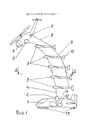
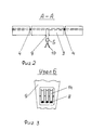
На фиг. 1 изображен ЛА во время полета. На фиг. 2 - разрез А-А. На фиг. 3 - узел Б.In FIG. 1 shows an aircraft during flight. In FIG. 2 - section aa. In FIG. 3 - node B.
ЛА содержит фюзеляж 1 с поперечной траверсой 2, присоединенной к гирлянде, состоящей из аэродинамических крыльев 3, поперечно соединенных стальными тросами 4. К тросам 4, в верхней части гирлянды, присоединена траверса 5, поперечно прикрепленная к вертолету 6. На вертолете 6 имеются лебедки 7 со стальными тросами 8, нижние концы которых присоединены к концам среднерасположенных балок 9 на всех крыльях 3. На концах балок 9 также установлен вертикальный киль 10 (вар. V - образный). В фюзеляже 1 также установлена емкость для топлива 11 с насосом для его перекачки 12. Фюзеляж 1 устанавливается на колесное шасси 13 либо шаровые колеса (см. патент №2585901). В задней части балок 9 установлены блоки шкивов 14, с которыми и взаимодействуют проходящие к нижерасположенным крыльям 3 тросы 8.The aircraft contains a
ЛА функционирует следующим образом. К траверсе 5 прикрепляются тросы 4, верхней части гирлянды разложенной на земле, а верхние концы тросов 8 присоединяются к лебедкам 7. Также производится присоединение топливных шлангов (не показаны) и вертолетом 6, все это поднимается в воздух. К этому моменту нижняя часть гирлянды с тросами 4 и 8 уже присоединена к траверсе 2, фюзеляжа 1, стоящего на земле. Далее производится синхронный разгон фюзеляжа 1 и вертолета 6. При этом фюзеляж 1 разгоняется по земле либо с помощью тяговой лебедки (вар. с использованием маховика) - не показаны, либо с использованием толкача/буксировщика (не показан). По мере разгона крылья 3 с помощью лебедок 7, а также тросов 8 постепенно переводятся с нулевого угла атаки на положительные, вплоть до необходимых для взлета. По мере набора скорости во время разгона вертолет 6 продольно наклоняется с перераспределением вертикальной составляющей силы, создаваемой несущим воздушным винтом, в пользу горизонтальной (т.е. возрастает тяговая сила за счет снижения подъемной). И это потребует переоборудования кабины пилотов (сохранения горизонтального положения пола при продольном наклоне машины). Для увеличения дальности полета основной запас топлива располагается в емкости 11 и постепенно перекачивается насосом 12 наверх, к вертолету 6, по шлангам (не показаны), прикрепленным к несущим тросам 4. Вероятно оптимальной будет скорость полета в диапазоне 120÷150 км/ч, с использованием уже существующих вертолетов (вар. Ми - 8, Ми - 26). Возможен и вар. использования для стартового разгона, открытого ж/д вагона повышенной грузоподъемности, с мото-толкачом // буксировщиком и тогда можно будет обойтись без использования шасси. Но с учетом того, что взлетно-посадочная скорость будет в диапазоне 70÷80 км/ч (при установке крыльев гирлянды на большие углы атаки) и при использовании шасси (много вар.), не потребуется специальная взлетно-посадочная полоса с твердым покрытием. При отсутствии необходимости в большегрузных транспортных или многоместных пассажирских перевозках вертолет может использоваться индивидуально, в обычном режиме.LA operates as follows.
Далее, в приложении (лист 5) приводятся сравнительные технические характеристики одиночного вертолета МИ - 8 (фактические) и летательного аппарата, использующего вертолет МИ - 8 в качестве буксировщика (расчетные).Further, in the appendix (sheet 5), comparative specifications of a single MI-8 helicopter (actual) and an aircraft using an MI-8 helicopter as a towing vehicle (calculated) are given.
ТЕХНИЧЕСКИЕ ХАРАКТЕРИСТИКИ ВЕРТОЛЕТА МИ - 8:TECHNICAL CHARACTERISTICS OF THE MI - 8 HELICOPTER:
Полная взлетная масса - 11100 кгGross take-off weight - 11100 kg
Максимальная скорость - 250 км/ч (с нормальным грузом)Maximum speed - 250 km / h (with normal load)
Дальность беспосадочного перелета - 465 кмNon-stop Range - 465 km
Коммерческая нагрузка - 4000 кг (при запасе топлива - 1470 кг)Payload - 4000 kg (with a fuel reserve of 1470 kg)
Удельный расход топлива - 0,6÷0,8 кг/т.кмSpecific fuel consumption - 0.6 ÷ 0.8 kg / t.km
РАСЧЕТНЫЕ ХАРАКТЕРИСТИКИ ЛЕТАТЕЛЬНОГО АППАРАТА С ВЕРТОЛЕТОМ-БУКСИРОВЩИКОМDESIGN CHARACTERISTICS OF THE AIRCRAFT WITH THE HELICOPTER-TOWING
Полная взлетная масса ~ 62000 кг (11100+45000+6000)Gross take-off weight ~ 62000 kg (11100 + 45000 + 6000)
Где: 11100 кг - масса вертолета МИ - 8Where: 11100 kg - MI helicopter mass - 8
45000 кг ~ масса фюзеляжа с перевозимым грузом и запасом топлива для вертолета45000 kg ~ fuselage mass with transported cargo and fuel supply for a helicopter
6000 кг ~ масса гирлянды (включая вес тросов, траверс и 10 крыльев, общей площадью ~ 1100÷1300 м)6000 kg ~ weight of a garland (including the weight of cables, traverses and 10 wings, with a total area of ~ 1100 ÷ 1300 m)
Коммерческая нагрузка ~ 15000÷20000 кг (в фюзеляже летательного аппарата и зависит от дальности)Commercial load ~ 15,000 ÷ 20,000 kg (in the fuselage of the aircraft and depends on range)
Крейсерская скорость полета ~ 140÷150 км/чCruising flight speed ~ 140 ÷ 150 km / h
Взлетно-посадочная скорость ~ 70÷80 км/чTakeoff and landing speed ~ 70 ÷ 80 km / h
Дальность беспосадочного перелета ~ 1200÷2000 км (с запасом топлива в фюзеляже лет. аппарата ~ 6000÷10000 кг)Range of non-stop flight ~ 1200 ÷ 2000 km (with a fuel reserve in the fuselage of years. Vehicle ~ 6000 ÷ 10000 kg)
Удельный расход топлива ~ 0,2÷0,3 кг/т. кмSpecific fuel consumption ~ 0.2 ÷ 0.3 kg / t. Km
Claims (5)
Priority Applications (1)
| Application Number | Priority Date | Filing Date | Title |
|---|---|---|---|
| RU2016138115A RU2639373C1 (en) | 2016-09-23 | 2016-09-23 | Aerial vehicle-1 |
Applications Claiming Priority (1)
| Application Number | Priority Date | Filing Date | Title |
|---|---|---|---|
| RU2016138115A RU2639373C1 (en) | 2016-09-23 | 2016-09-23 | Aerial vehicle-1 |
Publications (1)
| Publication Number | Publication Date |
|---|---|
| RU2639373C1 true RU2639373C1 (en) | 2017-12-21 |
Family
ID=63857225
Family Applications (1)
| Application Number | Title | Priority Date | Filing Date |
|---|---|---|---|
| RU2016138115A RU2639373C1 (en) | 2016-09-23 | 2016-09-23 | Aerial vehicle-1 |
Country Status (1)
| Country | Link |
|---|---|
| RU (1) | RU2639373C1 (en) |
Citations (3)
| Publication number | Priority date | Publication date | Assignee | Title |
|---|---|---|---|---|
| JP3287496B2 (en) * | 1993-04-30 | 2002-06-04 | 新日本製鐵株式会社 | Manufacturing method of bainite steel rail with excellent surface damage resistance |
| US20160152339A1 (en) * | 2013-04-02 | 2016-06-02 | Hood Technology Corporation | Helicopter-mediated system and method for launching and retrieving an aircraft |
| RU2595065C1 (en) * | 2015-07-02 | 2016-08-20 | Александр Поликарпович Лялин | Low speed heavy lift aircraft |
-
2016
- 2016-09-23 RU RU2016138115A patent/RU2639373C1/en active
Patent Citations (3)
| Publication number | Priority date | Publication date | Assignee | Title |
|---|---|---|---|---|
| JP3287496B2 (en) * | 1993-04-30 | 2002-06-04 | 新日本製鐵株式会社 | Manufacturing method of bainite steel rail with excellent surface damage resistance |
| US20160152339A1 (en) * | 2013-04-02 | 2016-06-02 | Hood Technology Corporation | Helicopter-mediated system and method for launching and retrieving an aircraft |
| RU2595065C1 (en) * | 2015-07-02 | 2016-08-20 | Александр Поликарпович Лялин | Low speed heavy lift aircraft |
Similar Documents
| Publication | Publication Date | Title |
|---|---|---|
| US6848650B2 (en) | Ground effect airplane | |
| US8485468B2 (en) | Ground-based apparatus for the take-off, landing and taxiing of aircraft | |
| RU2337855C1 (en) | Search-and-rescue aircraft | |
| US8579227B2 (en) | Vertical and horizontal flight aircraft “sky rover” | |
| RU2627965C1 (en) | High-speed amphibious rotorcraft | |
| RU2601470C1 (en) | Unmanned convertible high-speed helicopter | |
| RU2595065C1 (en) | Low speed heavy lift aircraft | |
| US12583582B2 (en) | VTOL transport clusters | |
| CN205971844U (en) | Fixed wing aircraft vertical take -off auxiliary system | |
| RU2608824C1 (en) | Helicopter external suspension | |
| RU2639373C1 (en) | Aerial vehicle-1 | |
| RU2654879C1 (en) | Airship and the method of its berthing | |
| RU2632387C1 (en) | Aircraft-2 | |
| RU2410289C1 (en) | Two-deck aircraft with rotary wings spaced apart by vertical tail | |
| RU2641375C1 (en) | Aircraft - 3 | |
| CN207902730U (en) | A kind of tiltrotor with separable function pod | |
| RU2111896C1 (en) | Polyfuselage seaplane | |
| RU2317220C1 (en) | Method of forming the system of forces of flying vehicle and flying vehicle-ground-air-amphibian for realization of this method | |
| CN117382882A (en) | Ducted fan aircraft capable of vertical take-off, landing and swimming on water and its operation method | |
| CN109760815A (en) | An airfield and refueling station located on the ground and/or in the air | |
| RU143725U1 (en) | Subsonic Passenger Airplane | |
| RU2798252C1 (en) | Device of the crane airship complex | |
| RU2714176C1 (en) | Multi-purpose super-heavy transport technological aircraft platform of short take-off and landing | |
| RU2406652C2 (en) | Vtol aircraft | |
| RU2629482C1 (en) | Unmanned combined helicopter |