RU2637388C2 - Board device and method of analysis of fluid environment in thermal engine - Google Patents
Board device and method of analysis of fluid environment in thermal engine Download PDFInfo
- Publication number
- RU2637388C2 RU2637388C2 RU2015127029A RU2015127029A RU2637388C2 RU 2637388 C2 RU2637388 C2 RU 2637388C2 RU 2015127029 A RU2015127029 A RU 2015127029A RU 2015127029 A RU2015127029 A RU 2015127029A RU 2637388 C2 RU2637388 C2 RU 2637388C2
- Authority
- RU
- Russia
- Prior art keywords
- led
- temperature
- supply current
- light source
- leds
- Prior art date
Links
- 238000004458 analytical method Methods 0.000 title description 13
- 239000012530 fluid Substances 0.000 title description 6
- 238000005259 measurement Methods 0.000 claims abstract description 101
- 230000010354 integration Effects 0.000 claims abstract description 61
- 239000012491 analyte Substances 0.000 claims abstract description 27
- 238000000295 emission spectrum Methods 0.000 claims abstract description 19
- 239000000126 substance Substances 0.000 claims abstract description 19
- 230000003993 interaction Effects 0.000 claims abstract description 3
- 238000001228 spectrum Methods 0.000 claims description 68
- 238000000034 method Methods 0.000 claims description 23
- 230000004907 flux Effects 0.000 claims description 16
- 230000003287 optical effect Effects 0.000 claims description 16
- 238000009529 body temperature measurement Methods 0.000 claims description 13
- 238000012360 testing method Methods 0.000 claims description 8
- 230000007257 malfunction Effects 0.000 claims description 4
- 230000005540 biological transmission Effects 0.000 claims description 3
- 230000007547 defect Effects 0.000 claims description 3
- 238000002405 diagnostic procedure Methods 0.000 claims description 2
- 230000001276 controlling effect Effects 0.000 claims 1
- 230000001105 regulatory effect Effects 0.000 claims 1
- 230000000694 effects Effects 0.000 abstract description 2
- 239000000446 fuel Substances 0.000 description 10
- 230000035945 sensitivity Effects 0.000 description 8
- 238000012007 large scale cell culture Methods 0.000 description 6
- 229930195733 hydrocarbon Natural products 0.000 description 5
- 150000002430 hydrocarbons Chemical class 0.000 description 5
- 239000000203 mixture Substances 0.000 description 5
- AYEKOFBPNLCAJY-UHFFFAOYSA-O thiamine pyrophosphate Chemical compound CC1=C(CCOP(O)(=O)OP(O)(O)=O)SC=[N+]1CC1=CN=C(C)N=C1N AYEKOFBPNLCAJY-UHFFFAOYSA-O 0.000 description 5
- 230000032683 aging Effects 0.000 description 4
- 230000008859 change Effects 0.000 description 4
- 238000012937 correction Methods 0.000 description 4
- 238000004519 manufacturing process Methods 0.000 description 4
- 239000004215 Carbon black (E152) Substances 0.000 description 3
- 238000006243 chemical reaction Methods 0.000 description 3
- 239000007787 solid Substances 0.000 description 3
- 238000004611 spectroscopical analysis Methods 0.000 description 3
- 101150072399 LSC1 gene Proteins 0.000 description 2
- 239000013256 coordination polymer Substances 0.000 description 2
- 239000004065 semiconductor Substances 0.000 description 2
- 230000003595 spectral effect Effects 0.000 description 2
- XLYOFNOQVPJJNP-UHFFFAOYSA-N water Chemical compound O XLYOFNOQVPJJNP-UHFFFAOYSA-N 0.000 description 2
- 206010002091 Anaesthesia Diseases 0.000 description 1
- 102100023882 Endoribonuclease ZC3H12A Human genes 0.000 description 1
- 101710112715 Endoribonuclease ZC3H12A Proteins 0.000 description 1
- 101001096074 Homo sapiens Regenerating islet-derived protein 4 Proteins 0.000 description 1
- 101100511042 Oryza sativa subsp. japonica LFL1 gene Proteins 0.000 description 1
- 108700012361 REG2 Proteins 0.000 description 1
- 101150108637 REG2 gene Proteins 0.000 description 1
- 108091058543 REG3 Proteins 0.000 description 1
- 101100120298 Rattus norvegicus Flot1 gene Proteins 0.000 description 1
- 101100412403 Rattus norvegicus Reg3b gene Proteins 0.000 description 1
- 102100027336 Regenerating islet-derived protein 3-alpha Human genes 0.000 description 1
- 102100037889 Regenerating islet-derived protein 4 Human genes 0.000 description 1
- 230000002159 abnormal effect Effects 0.000 description 1
- 230000005856 abnormality Effects 0.000 description 1
- 230000009471 action Effects 0.000 description 1
- 238000001949 anaesthesia Methods 0.000 description 1
- 230000037005 anaesthesia Effects 0.000 description 1
- 230000015572 biosynthetic process Effects 0.000 description 1
- 239000011248 coating agent Substances 0.000 description 1
- 238000000576 coating method Methods 0.000 description 1
- 239000012141 concentrate Substances 0.000 description 1
- 238000009833 condensation Methods 0.000 description 1
- 230000005494 condensation Effects 0.000 description 1
- 238000011109 contamination Methods 0.000 description 1
- 238000001816 cooling Methods 0.000 description 1
- 238000002425 crystallisation Methods 0.000 description 1
- 230000008025 crystallization Effects 0.000 description 1
- 238000010586 diagram Methods 0.000 description 1
- 239000006185 dispersion Substances 0.000 description 1
- 238000005516 engineering process Methods 0.000 description 1
- 230000001771 impaired effect Effects 0.000 description 1
- 238000009434 installation Methods 0.000 description 1
- 238000012423 maintenance Methods 0.000 description 1
- 238000012544 monitoring process Methods 0.000 description 1
- 150000002894 organic compounds Chemical class 0.000 description 1
- QGVYYLZOAMMKAH-UHFFFAOYSA-N pegnivacogin Chemical compound COCCOC(=O)NCCCCC(NC(=O)OCCOC)C(=O)NCCCCCCOP(=O)(O)O QGVYYLZOAMMKAH-UHFFFAOYSA-N 0.000 description 1
- 238000012545 processing Methods 0.000 description 1
- 238000002106 pulse oximetry Methods 0.000 description 1
- 239000000758 substrate Substances 0.000 description 1
- 230000007704 transition Effects 0.000 description 1
- 230000017105 transposition Effects 0.000 description 1
Images
Classifications
-
- G—PHYSICS
- G01—MEASURING; TESTING
- G01N—INVESTIGATING OR ANALYSING MATERIALS BY DETERMINING THEIR CHEMICAL OR PHYSICAL PROPERTIES
- G01N21/00—Investigating or analysing materials by the use of optical means, i.e. using sub-millimetre waves, infrared, visible or ultraviolet light
- G01N21/17—Systems in which incident light is modified in accordance with the properties of the material investigated
- G01N21/25—Colour; Spectral properties, i.e. comparison of effect of material on the light at two or more different wavelengths or wavelength bands
- G01N21/31—Investigating relative effect of material at wavelengths characteristic of specific elements or molecules, e.g. atomic absorption spectrometry
- G01N21/35—Investigating relative effect of material at wavelengths characteristic of specific elements or molecules, e.g. atomic absorption spectrometry using infrared light
- G01N21/3577—Investigating relative effect of material at wavelengths characteristic of specific elements or molecules, e.g. atomic absorption spectrometry using infrared light for analysing liquids, e.g. polluted water
-
- G—PHYSICS
- G01—MEASURING; TESTING
- G01N—INVESTIGATING OR ANALYSING MATERIALS BY DETERMINING THEIR CHEMICAL OR PHYSICAL PROPERTIES
- G01N21/00—Investigating or analysing materials by the use of optical means, i.e. using sub-millimetre waves, infrared, visible or ultraviolet light
- G01N21/17—Systems in which incident light is modified in accordance with the properties of the material investigated
- G01N21/25—Colour; Spectral properties, i.e. comparison of effect of material on the light at two or more different wavelengths or wavelength bands
- G01N21/27—Colour; Spectral properties, i.e. comparison of effect of material on the light at two or more different wavelengths or wavelength bands using photo-electric detection ; circuits for computing concentration
- G01N21/274—Calibration, base line adjustment, drift correction
-
- G—PHYSICS
- G01—MEASURING; TESTING
- G01N—INVESTIGATING OR ANALYSING MATERIALS BY DETERMINING THEIR CHEMICAL OR PHYSICAL PROPERTIES
- G01N21/00—Investigating or analysing materials by the use of optical means, i.e. using sub-millimetre waves, infrared, visible or ultraviolet light
- G01N21/17—Systems in which incident light is modified in accordance with the properties of the material investigated
- G01N21/25—Colour; Spectral properties, i.e. comparison of effect of material on the light at two or more different wavelengths or wavelength bands
- G01N21/31—Investigating relative effect of material at wavelengths characteristic of specific elements or molecules, e.g. atomic absorption spectrometry
- G01N21/35—Investigating relative effect of material at wavelengths characteristic of specific elements or molecules, e.g. atomic absorption spectrometry using infrared light
- G01N21/3504—Investigating relative effect of material at wavelengths characteristic of specific elements or molecules, e.g. atomic absorption spectrometry using infrared light for analysing gases, e.g. multi-gas analysis
-
- G—PHYSICS
- G01—MEASURING; TESTING
- G01J—MEASUREMENT OF INTENSITY, VELOCITY, SPECTRAL CONTENT, POLARISATION, PHASE OR PULSE CHARACTERISTICS OF INFRARED, VISIBLE OR ULTRAVIOLET LIGHT; COLORIMETRY; RADIATION PYROMETRY
- G01J3/00—Spectrometry; Spectrophotometry; Monochromators; Measuring colours
- G01J3/02—Details
- G01J3/10—Arrangements of light sources specially adapted for spectrometry or colorimetry
-
- G—PHYSICS
- G01—MEASURING; TESTING
- G01N—INVESTIGATING OR ANALYSING MATERIALS BY DETERMINING THEIR CHEMICAL OR PHYSICAL PROPERTIES
- G01N21/00—Investigating or analysing materials by the use of optical means, i.e. using sub-millimetre waves, infrared, visible or ultraviolet light
- G01N21/17—Systems in which incident light is modified in accordance with the properties of the material investigated
- G01N21/25—Colour; Spectral properties, i.e. comparison of effect of material on the light at two or more different wavelengths or wavelength bands
- G01N21/31—Investigating relative effect of material at wavelengths characteristic of specific elements or molecules, e.g. atomic absorption spectrometry
- G01N21/314—Investigating relative effect of material at wavelengths characteristic of specific elements or molecules, e.g. atomic absorption spectrometry with comparison of measurements at specific and non-specific wavelengths
- G01N2021/3181—Investigating relative effect of material at wavelengths characteristic of specific elements or molecules, e.g. atomic absorption spectrometry with comparison of measurements at specific and non-specific wavelengths using LEDs
-
- G—PHYSICS
- G01—MEASURING; TESTING
- G01N—INVESTIGATING OR ANALYSING MATERIALS BY DETERMINING THEIR CHEMICAL OR PHYSICAL PROPERTIES
- G01N21/00—Investigating or analysing materials by the use of optical means, i.e. using sub-millimetre waves, infrared, visible or ultraviolet light
- G01N21/17—Systems in which incident light is modified in accordance with the properties of the material investigated
- G01N21/25—Colour; Spectral properties, i.e. comparison of effect of material on the light at two or more different wavelengths or wavelength bands
- G01N21/27—Colour; Spectral properties, i.e. comparison of effect of material on the light at two or more different wavelengths or wavelength bands using photo-electric detection ; circuits for computing concentration
-
- G—PHYSICS
- G01—MEASURING; TESTING
- G01N—INVESTIGATING OR ANALYSING MATERIALS BY DETERMINING THEIR CHEMICAL OR PHYSICAL PROPERTIES
- G01N2201/00—Features of devices classified in G01N21/00
- G01N2201/06—Illumination; Optics
- G01N2201/062—LED's
-
- G—PHYSICS
- G01—MEASURING; TESTING
- G01N—INVESTIGATING OR ANALYSING MATERIALS BY DETERMINING THEIR CHEMICAL OR PHYSICAL PROPERTIES
- G01N2201/00—Features of devices classified in G01N21/00
- G01N2201/06—Illumination; Optics
- G01N2201/062—LED's
- G01N2201/0624—Compensating variation in output of LED source
-
- G—PHYSICS
- G01—MEASURING; TESTING
- G01N—INVESTIGATING OR ANALYSING MATERIALS BY DETERMINING THEIR CHEMICAL OR PHYSICAL PROPERTIES
- G01N2201/00—Features of devices classified in G01N21/00
- G01N2201/12—Circuits of general importance; Signal processing
- G01N2201/121—Correction signals
-
- G—PHYSICS
- G01—MEASURING; TESTING
- G01N—INVESTIGATING OR ANALYSING MATERIALS BY DETERMINING THEIR CHEMICAL OR PHYSICAL PROPERTIES
- G01N2201/00—Features of devices classified in G01N21/00
- G01N2201/12—Circuits of general importance; Signal processing
- G01N2201/121—Correction signals
- G01N2201/1211—Correction signals for temperature
-
- G—PHYSICS
- G01—MEASURING; TESTING
- G01N—INVESTIGATING OR ANALYSING MATERIALS BY DETERMINING THEIR CHEMICAL OR PHYSICAL PROPERTIES
- G01N2201/00—Features of devices classified in G01N21/00
- G01N2201/12—Circuits of general importance; Signal processing
- G01N2201/124—Sensitivity
-
- G—PHYSICS
- G01—MEASURING; TESTING
- G01N—INVESTIGATING OR ANALYSING MATERIALS BY DETERMINING THEIR CHEMICAL OR PHYSICAL PROPERTIES
- G01N2201/00—Features of devices classified in G01N21/00
- G01N2201/12—Circuits of general importance; Signal processing
- G01N2201/124—Sensitivity
- G01N2201/1242—Validating, e.g. range invalidation, suspending operation
-
- G—PHYSICS
- G01—MEASURING; TESTING
- G01N—INVESTIGATING OR ANALYSING MATERIALS BY DETERMINING THEIR CHEMICAL OR PHYSICAL PROPERTIES
- G01N2201/00—Features of devices classified in G01N21/00
- G01N2201/12—Circuits of general importance; Signal processing
- G01N2201/124—Sensitivity
- G01N2201/1247—Thresholding
-
- G—PHYSICS
- G01—MEASURING; TESTING
- G01N—INVESTIGATING OR ANALYSING MATERIALS BY DETERMINING THEIR CHEMICAL OR PHYSICAL PROPERTIES
- G01N2201/00—Features of devices classified in G01N21/00
- G01N2201/12—Circuits of general importance; Signal processing
- G01N2201/127—Calibration; base line adjustment; drift compensation
- G01N2201/12723—Self check capacity; automatic, periodic step of checking
Landscapes
- Physics & Mathematics (AREA)
- Spectroscopy & Molecular Physics (AREA)
- Health & Medical Sciences (AREA)
- Life Sciences & Earth Sciences (AREA)
- Chemical & Material Sciences (AREA)
- Analytical Chemistry (AREA)
- Biochemistry (AREA)
- General Health & Medical Sciences (AREA)
- General Physics & Mathematics (AREA)
- Immunology (AREA)
- Pathology (AREA)
- Engineering & Computer Science (AREA)
- Mathematical Physics (AREA)
- Theoretical Computer Science (AREA)
- Investigating Or Analysing Materials By Optical Means (AREA)
- Investigating, Analyzing Materials By Fluorescence Or Luminescence (AREA)
- Spectrometry And Color Measurement (AREA)
- Optical Measuring Cells (AREA)
Abstract
Description
Настоящее изобретение относится к анализу текучих сред методом спектрометрии. Настоящее изобретение находит свое применение, в частности, но не исключительно для анализа текучих сред в тепловом двигателе, в частности, для анализа углеводородов, используемых в качестве топлива в таком двигателе. Этот анализ касается всех тепловых двигателей, то есть двигателей, применяемых на наземном, морском и воздушном транспорте, военных двигателей или стационарных двигателей.The present invention relates to the analysis of fluids by spectrometry. The present invention finds its application, in particular, but not exclusively for the analysis of fluids in a heat engine, in particular for the analysis of hydrocarbons used as fuel in such an engine. This analysis applies to all heat engines, i.e. engines used in land, sea and air transport, military engines or stationary engines.
Ужесточение норм, регламентирующих охрану окружающей среды, требует от конструкторов и пользователей тепловых двигателей вести поиск оптимизации расхода топлива и снижения вредных выбросов двигателей. Однако, как выяснилось, некоторые характеристики топлива, такие как его состав, напрямую влияют на характеристики и нормальную работу тепловых двигателей. Выяснилось также, что некоторые из этих характеристик могут меняться, в частности, в случае топлива на основе углеводородов, в частности, в зависимости от происхождения топлива. Действительно, считается, что некоторые характеристики, такие как состав топлива на основе углеводородов, могут меняться на 15-40% и даже больше. Вместе с тем, знание этих характеристик позволяет определять некоторые параметры регулирования двигателя, чтобы снижать расход топлива и вредные выбросы двигателя. Кроме того, знание качественных характеристик топлива позволяет обнаруживать загрязнения или аномалии этого топлива и, следовательно, предупреждать негативные последствия для двигателя или транспортного средства в целом.The toughening of the rules governing the protection of the environment requires designers and users of heat engines to search for optimized fuel consumption and reduce harmful engine emissions. However, as it turned out, some characteristics of the fuel, such as its composition, directly affect the characteristics and normal operation of heat engines. It also turned out that some of these characteristics can change, in particular, in the case of hydrocarbon-based fuels, in particular, depending on the origin of the fuel. Indeed, it is believed that some characteristics, such as the composition of hydrocarbon-based fuels, can vary by 15-40% or even more. At the same time, knowledge of these characteristics makes it possible to determine some parameters of engine regulation in order to reduce fuel consumption and harmful engine emissions. In addition, knowledge of the qualitative characteristics of the fuel allows you to detect contamination or anomalies of this fuel and, therefore, prevent negative consequences for the engine or vehicle as a whole.
Следовательно, необходимо анализировать такие характеристики, как состав топлива питания теплового двигателя, и учитывать полученные результаты для коррекции рабочих параметров двигателя. В связи с этим для анализа углеводородов или углеводородных смесей применяют спектрометрию в близкой инфракрасной области (700-2500 нм).Therefore, it is necessary to analyze such characteristics as the composition of the fuel supply of the heat engine, and take into account the results obtained for the correction of engine operating parameters. In this regard, for the analysis of hydrocarbons or hydrocarbon mixtures, spectrometry in the near infrared region (700–2500 nm) is used.
Датчик, основанный на спектрометрии, в частности, в близкой инфракрасной области, содержит спектрометр и вычислительное устройство обработки данных, позволяющее преобразовать необработанные выходные сигналы (необработанный спектр) спектрометра в качественную характеристику измеряемого вещества. Спектрометр содержит источник света, который охватывает по меньшей мере одну полосу длин волн, в которой необходимо осуществлять анализ, измерительную ячейку, в которой взаимодействуют свет, излучаемый источником света, и анализируемое вещество, и датчик, который выдает спектр света на выходе измерительной ячейки. Спектрометр может измерять спектр анализируемого вещества при пропускании, отражении или поглощении светового пучка, излучаемого источником света. Спектрометр в основном характеризуется своим спектральным диапазоном анализа (ширина и положение генерируемого спектра), своей чувствительностью анализа или числом точек измерения, образующих генерируемый спектр, и своей точностью измерения.A sensor based on spectrometry, in particular in the near infrared region, contains a spectrometer and a computing device for data processing, which allows converting the raw output signals (raw spectrum) of the spectrometer into a qualitative characteristic of the measured substance. The spectrometer contains a light source that covers at least one wavelength band in which it is necessary to analyze, a measuring cell in which the light emitted by the light source and the analyte interact, and a sensor that provides a light spectrum at the output of the measuring cell. A spectrometer can measure the spectrum of an analyte by transmitting, reflecting, or absorbing a light beam emitted by a light source. The spectrometer is mainly characterized by its spectral range of analysis (width and position of the generated spectrum), its sensitivity of analysis, or the number of measurement points forming the generated spectrum, and its measurement accuracy.
Современные спектрометры, как правило, разработанные для лабораторий или для дорогих и сложных промышленных установок, не адаптированы к окружающей среде теплового двигателя и, в частности, к окружающей среде автомобиля, где они могут подвергаться воздействию сильных вибраций и экстремальных температур. Не говоря уже о своей сложности, высокой стоимости, относительно большом габарите и необходимости обслуживания, эти приборы требуют применения многочисленных оптических компонентов, что связано с жесткими требованиями, относящимися к наладке, манипулированию и хранению.Modern spectrometers, usually designed for laboratories or for expensive and complex industrial installations, are not adapted to the environment of a heat engine and, in particular, to the environment of a car, where they can be exposed to strong vibrations and extreme temperatures. Not to mention its complexity, high cost, relatively large size and the need for maintenance, these devices require the use of numerous optical components, which is associated with stringent requirements related to commissioning, handling and storage.
Поэтому существует необходимость в реализации спектрометра, совместимого с масштабами серийного производства, имеющего стоимость, соотносимую со стоимостью автомобильных компонентов, и адаптированного к окружающей среде автомобиля. Для этого особый интерес представляет использование одного или нескольких светодиодов (LED) в качестве источника света.Therefore, there is a need for a spectrometer compatible with the scale of mass production, having a cost comparable to the cost of automotive components, and adapted to the environment of the car. Of particular interest is the use of one or more light emitting diodes (LEDs) as a light source.
Однако при этом следует отметить, что измеряемый спектр, который является характеристикой качества и/или состава анализируемого вещества, подвержен влиянию внешних факторов, таких как температура, и также характеристик спектра светового пучка, взаимодействующего с анализируемым веществом. К тому же светодиоды подвержены старению, поэтому их спектр излучения меняется в течение времени, как указано в статье из LED Journal "LED lighting Life Prediction", Jianzhong Jiao, Ph. D., Director of Regulations & Emerging Technologies, Osram Opto Semiconductors, Inc, Oct. 2009. Кроме того, как известно и доказано, спектрометр в близкой инфракрасной области является чувствительным к температуре (что описано, например, в публикации "On-line monitoring of batch cooling crystallization of organic compounds method" - Chemometrics and Intelligent Laboratory Systems 96 (2009) 49-58, Zeng-Ping Chen, Julian Morris, Antonina Borissova, Shahid Khan, Tariq Mahmud, Rado Penchev, Kevin j. Roberts). Таким образом, инфракрасный спектрометр, использующий свет на основе светодиода, оказывается исключительно чувствительным к температуре. Действительно, спектр излучения светодиода значительно меняется как по интенсивности, так и по отклонению длины волны от максимального пика, когда температура меняется всего на несколько градусов, как показано в публикации "Temperature Dependence of LED and its Theoretical Effect on Pulse Oximetry", British Journal of Anaesthesia, 1991, Vol. 67, No 5 638-643 (K.J. Reynolds, B.A., M.SC, J.P. De Kock, B.A., L. Tarassenko, M.A., D.PHIL., C.EKG., M.I.E.E. and J.T.B. Moyle, M.B., I.ENG., M.rNST.M.c, M.I.ELEC.I.E.).However, it should be noted that the measured spectrum, which is a characteristic of the quality and / or composition of the analyte, is influenced by external factors, such as temperature, and also the characteristics of the spectrum of the light beam interacting with the analyte. Moreover, LEDs are subject to aging, so their emission spectrum changes over time, as indicated in an article from the LED Journal "LED lighting Life Prediction", Jianzhong Jiao, Ph. D., Director of Regulations & Emerging Technologies, Osram Opto Semiconductors, Inc, Oct. 2009. In addition, as is known and proved, the near infrared spectrometer is temperature sensitive (as described, for example, in the publication "On-line monitoring of batch cooling crystallization of organic compounds method" - Chemometrics and Intelligent Laboratory Systems 96 (2009 ) 49-58, Zeng-Ping Chen, Julian Morris, Antonina Borissova, Shahid Khan, Tariq Mahmud, Rado Penchev, Kevin j. Roberts). Thus, an infrared spectrometer using LED-based light is extremely temperature sensitive. Indeed, the emission spectrum of the LED varies significantly both in intensity and in the deviation of the wavelength from the maximum peak when the temperature changes by only a few degrees, as shown in the publication "Temperature Dependence of LED and its Theoretical Effect on Pulse Oximetry", British Journal of Anaesthesia, 1991, Vol. 67, No. 5 638-643 (KJ Reynolds, BA, M.SC, JP De Kock, BA, L. Tarassenko, MA, D.PHIL., C.EKG., MIEE and JTB Moyle, MB, I.ENG. , M.rNST.Mc, MIELEC.IE).
Однако датчик, связанный с тепловым двигателем, установленным, в частности, на транспортном средстве, должен работать в очень широком температурном диапазоне (в зависимости от применения современные стандарты предусматривают температурные диапазоны от -40°C до +105°C и даже до +150°C). Кроме того, бортовые датчики должны гарантированно иметь большой срок службы (в зависимости от применения современные стандарты предусматривают срок службы от нескольких тысяч часов до нескольких сотен тысяч часов). Поэтому для обеспечения нормальной работы спектрометра крайне необходимо контролировать в реальном времени влияние температуры и старения источника света для обеспечения качественного определения анализируемого вещества, которое должно быть точным и надежным.However, the sensor associated with the heat engine installed, in particular, on the vehicle, must operate in a very wide temperature range (depending on the application, modern standards provide temperature ranges from -40 ° C to + 105 ° C and even up to + 150 ° C) In addition, on-board sensors must be guaranteed to have a long service life (depending on the application, modern standards provide a service life from several thousand hours to several hundred thousand hours). Therefore, to ensure the normal operation of the spectrometer, it is imperative to monitor in real time the influence of temperature and aging of the light source to ensure a qualitative determination of the analyte, which must be accurate and reliable.
Следовательно, необходимо также разработать спектрометр, выдающий стабильный спектральный сигнал, с максимально постоянным соотношением сигнал/шум, причем в широком диапазоне изменения окружающей температуры и на длительный срок работы.Therefore, it is also necessary to develop a spectrometer that produces a stable spectral signal with the most constant signal to noise ratio, and in a wide range of changes in ambient temperature and for a long period of operation.
Согласно вариантам выполнения, предложен способ управления спектрометром для анализа вещества, при этом спектрометр содержит источник света, содержащий несколько светодиодов, спектры излучения которых охватывают в комбинации полосу длин волн анализа, при этом способ содержит этапы, на которых: подают ток питания по меньшей мере на один из светодиодов для его включения и измеряют силу света, излучаемого источником света, посредством измерения тока на контакте по меньшей мере одного из других светодиодов, который остается выключенным, в зависимости от каждого измерения силы света определяют заданное значение силы тока каждого включенного светодиода и регулируют ток питания каждого включенного светодиода таким образом, чтобы он соответствовал заданному значению.According to embodiments, a method for controlling a spectrometer for analyzing a substance is provided, the spectrometer comprising a light source comprising several LEDs whose emission spectra encompass the analysis wavelength band in combination, the method comprising the steps of: supplying at least a supply current one of the LEDs to turn it on and measure the intensity of the light emitted by the light source by measuring the current at the contact of at least one of the other LEDs that remains off, in The dependence of the intensity of each measurement is determined a predetermined value of current intensity for each LED included and controlled supply current of each LED included so as to correspond to a predetermined value.
Согласно варианту выполнения, способ содержит этапы, на которых осуществляют последовательное включение групп по меньшей мере из одного светодиода, при этом светодиоды одной группы имеют по существу идентичные спектры излучения, тогда как другие светодиоды остаются выключенными, измерение силы света для каждого из других остающихся выключенными светодиодов и регулирование, в зависимости от каждого полученного измерения силы света, заданного значения тока питания включенного светодиода.According to an embodiment, the method comprises the steps of sequentially switching on groups of at least one LED, the LEDs of one group having substantially identical emission spectra, while the other LEDs remain off, measuring the light intensity for each of the other LEDs remaining off and regulation, depending on each received measurement of the luminous intensity, the set value of the supply current of the LED on.
Согласно варианту выполнения, способ содержит этапы, на которых: в зависимости от измерений силы света определяют значение времени интегрирования фоточувствительных элементов датчика спектрометра, расположенных на пути светового пучка, излучаемого источником света и взаимодействовавшего с анализируемым веществом, и, если значение времени интегрирования и/или заданное значение тока питания каждого включенного светодиода находится в интервале между пороговыми значениями, на каждый включенный светодиод подают ток питания, регулируемый в зависимости от заданного значения тока питания, время интегрирования каждого фоточувствительного элемента регулируют по определенному значению времени интегрирования, и при помощи каждого элемента датчика получают измерения силы света, позволяющие сформировать спектр.According to an embodiment, the method comprises the steps in which: depending on the light intensity measurements, the integration time of the photosensitive elements of the spectrometer sensor is determined, located on the path of the light beam emitted by the light source and interacting with the analyte, and if the integration time and / or the set value of the supply current for each LED on is in the interval between threshold values, for each LED on, the supply current is supplied, adjustable minutes depending on the predetermined supply current value, the integration time of each of the photosensitive member is controlled by a particular value of the integration time, and by means of each sensor element measuring the intensity obtained, allowing to form a spectrum.
Согласно варианту выполнения, определяют новые заданные значения тока питания каждого включенного светодиода и/или время интегрирования каждого элемента и подают ток питания, соответствующий определенному заданному значению тока питания, на каждый включенный светодиод, пока определенное значение времени интегрирования не находится в интервале между пороговыми значениями.According to an embodiment, the new setpoint values of the supply current of each LED on and / or the integration time of each element are determined and the supply current corresponding to the determined setpoint value of the supply current is supplied to each LED that is turned on until a certain value of the integration time is in the range between the threshold values.
Согласно варианту выполнения, заданное значение тока питания каждого включенного светодиода регулируют также в зависимости от измерения силы света, поступающего от фотодиода источника света, и/или от измерения температуры источника света, и/или от измерения силы тока или напряжения питания каждого включенного светодиода.According to an embodiment, the set value of the supply current of each LED on is also controlled depending on the measurement of the light intensity coming from the photodiode of the light source, and / or on the measurement of the temperature of the light source, and / or the measurement of the current strength or supply voltage of each LED on.
Согласно варианту выполнения, способ содержит тестовые этапы автоматической диагностики, включающие в себя по меньшей мере одно из следующих сравнений: сравнения, чтобы определить, что измерения силы света и/или измерения тока питания, подаваемого на включенный светодиод, и/или измерения температуры источника света согласуются между собой и с каждым заданным значением тока питания включенного светодиода, сравнения заданного значения тока питания, подаваемого на каждый включенный светодиод, с минимальными и максимальными значениями, и, если одно из сравнений приводит к выявлению дефекта, спектрометр переключают в режим работы с ухудшенными параметрами или в режим неисправности.According to an embodiment, the method comprises automatic diagnostic test steps including at least one of the following comparisons: comparisons to determine what measurements of luminous intensity and / or measurements of the power current supplied to the LED are on and / or measurements of the temperature of the light source are consistent with each other and with each set value of the supply current of the LED turned on, comparing the set value of the supply current supplied to each included LED with the minimum and maximum values, and, if one of the comparisons leads to the identification of a defect, the spectrometer is switched to the operating mode with degraded parameters or to the malfunction mode.
Согласно варианту выполнения, способ содержит этап коррекции измерений силы света с учетом отклонения температуры анализируемого вещества и/или температуры датчика от контрольной температуры таким образом, чтобы получить скорректированные измерения силы света на основании измерений, произведенных при контрольной температуре, при этом скорректированные измерения образуют скорректированный спектр.According to an embodiment, the method comprises the step of correcting the light intensity measurements taking into account the deviation of the analyte temperature and / or the sensor temperature from the control temperature so as to obtain corrected light intensity measurements based on measurements taken at the control temperature, wherein the corrected measurements form a corrected spectrum .
Согласно варианту выполнения, способ содержит этапы получения скорректированного спектра для каждого светодиода и суммирования полученных скорректированных спектров посредством применения коэффициентов взвешивания для получения результирующего спектра, и, в случае необходимости, вычисления среднего значения результирующих спектров, при этом число усредненных спектров может зависеть от режима работы спектрометра, нормального или с ухудшенными параметрами.According to an embodiment, the method comprises the steps of obtaining the adjusted spectrum for each LED and summing the obtained corrected spectra by applying weighting factors to obtain the resulting spectrum, and, if necessary, calculating the average value of the resulting spectra, while the number of averaged spectra may depend on the operating mode of the spectrometer normal or with impaired parameters.
Согласно варианту выполнения, способ включает в себя калибровку спектрометра, в том числе: этапы определения минимального и максимального значений соответствия измерений силы света светового потока, производимого каждым светодиодом, с заданными значениями тока питания каждого из светодиодов и/или с температурой источника света, и/или этапы определения минимального и максимального заданных значений тока питания источника света, и/или этапы определения минимального и максимального значений времени интегрирования фоточувствительных элементов датчика, и/или этапы, осуществляемые в присутствии одного или нескольких контрольных веществ, для определения функции, дающей оптимальное время интегрирования фоточувствительного элемента датчика в зависимости от измерений силы света светового потока, производимого каждым светодиодом, и/или этапы, осуществляемые в присутствии одного или нескольких контрольных веществ, в ходе которых отдельно изменяют температуру источника света и/или температуру датчика, и/или температуру контрольного вещества, собирают измерения силы света, получаемые при помощи датчика, заданные значения тока питания светодиодов, элементов датчика, и измерения температуры, и определяют функцию, дающую скорректированное измерение силы света, соответствующее контрольной температуре, в зависимости от собранных измерений.According to an embodiment, the method includes calibrating the spectrometer, including: the steps of determining the minimum and maximum values of the correspondence of light intensity measurements of the light flux produced by each LED with the given values of the supply current of each LED and / or with the temperature of the light source, and / or the steps of determining the minimum and maximum preset values of the power supply current of the light source, and / or the steps of determining the minimum and maximum values of the integration time of photosensitive sensor elements, and / or steps carried out in the presence of one or more control substances, to determine a function that gives the optimal integration time of the photosensitive sensor element depending on light intensity measurements of the light flux produced by each LED, and / or steps carried out in the presence of one or several control substances during which the temperature of the light source and / or the temperature of the sensor and / or the temperature of the control substance are separately changed, measurements of light intensity are collected Obtained by the sensor setpoints power LED current, the sensor element and the temperature measurement, and determine the function which gives the corrected measurement of intensity corresponding to the reference temperature, depending upon the collected measurements.
Согласно вариантам выполнения, предложен также спектрометр, содержащий источник света, содержащий несколько светодиодов, спектры излучения которых охватывают в комбинации полосу длин волн анализа, датчик, содержащий фоточувствительные элементы, расположенные на пути светового пучка после его взаимодействия с анализируемым веществом, и устройство управления, регулирующее заданные значения тока питания светодиодов источника света и время интегрирования фоточувствительных элементов, при этом устройство управления выполнено с возможностью осуществления описанного выше способа.According to embodiments, there is also proposed a spectrometer comprising a light source containing several LEDs, the emission spectra of which cover a combination of the analysis wavelength, a sensor containing photosensitive elements located in the path of the light beam after its interaction with the analyte, and a control device that controls the set values of the supply current of the LEDs of the light source and the integration time of the photosensitive elements, while the control device is made with possible spine of the above-described method.
Согласно варианту выполнения, спектрометр выполнен с возможностью включения только одного светодиода источника света за один раз и с возможностью получения измерения силы света посредством измерения тока на контакте каждого из выключенных светодиодов источника света.According to an embodiment, the spectrometer is configured to turn on only one light source LED at a time and to obtain a measurement of light intensity by measuring the current at the contact of each of the turned off light source LEDs.
Согласно варианту выполнения, источник света выполнен с возможностью подачи на устройство управления напряжений и/или токов питания светодиодов.According to an embodiment, the light source is configured to supply voltage and / or power currents to the LEDs to the control device.
Согласно варианту выполнения, светодиоды установлены в одном электронном компоненте, в случае необходимости, вместе с фотодиодом и/или температурным датчиком.According to an embodiment, the LEDs are mounted in a single electronic component, if necessary, together with a photodiode and / or a temperature sensor.
Согласно варианту выполнения, спектрометр содержит температурный датчик, выдающий измерения температуры источника света, и/или температурный датчик, выдающий измерения температуры датчика, и/или температурный датчик, выдающий измерения температуры анализируемого вещества.According to an embodiment, the spectrometer comprises a temperature sensor outputting temperature measurements of the light source, and / or a temperature sensor outputting temperature measurements of the sensor, and / or a temperature sensor outputting temperature measurements of the analyte.
Согласно варианту выполнения, спектрометр содержит измерительную ячейку, в которой анализируемое вещество взаимодействует со световым пучком, оптический элемент для формирования пучка на выходе источника света и его передачи в измерительную ячейку, фильтр длины волны, выполненный с возможностью пространственного распределения различных длин волн светового пучка на выходе измерительной ячейки и их передачи в различные фоточувствительные элементы датчика, при этом источник света, оптический элемент, измерительная ячейка, фильтр и датчик соединены таким образом, чтобы избегать образования воздушной зоны, через которую может проходить световой пучок, между источником света и датчиком.According to an embodiment, the spectrometer comprises a measuring cell in which the analyte interacts with the light beam, an optical element for forming a beam at the output of the light source and transmitting it to the measuring cell, a wavelength filter configured to spatially distribute different wavelengths of the light beam at the output measuring cell and their transmission to various photosensitive elements of the sensor, with the light source, optical element, measuring cell, filter and dates The sensors are connected in such a way as to avoid the formation of an air zone through which the light beam can pass between the light source and the sensor.
Далее следует описание не ограничительных примеров выполнения изобретения и осуществления способа со ссылками на прилагаемые чертежи, на которых:The following is a description of non-limiting examples of carrying out the invention and the implementation of the method with reference to the accompanying drawings, in which:
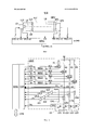
фиг. 1 - схема спектрометра в соответствии с изобретением;FIG. 1 is a diagram of a spectrometer in accordance with the invention;
фиг. 2 - электронная схема управления источником света спектрометра согласно варианту выполнения;FIG. 2 is an electronic circuit for controlling the light source of a spectrometer according to an embodiment;
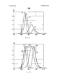
фиг. 3А и 3B - спектры излучения светодиодов в виде кривых изменения силы излучаемого света в зависимости от длины волны;FIG. 3A and 3B are emission spectra of LEDs in the form of curves of changes in the strength of the emitted light depending on the wavelength;
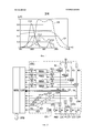
фиг. 4 - спектры чувствительности светодиодов в виде кривых изменения силы генерируемого электрического тока в зависимости от длины волны;FIG. 4 - sensitivity spectra of LEDs in the form of curves of changes in the strength of the generated electric current depending on the wavelength;
фиг. 5 - электронная схема управления источником света спектрометра согласно другому варианту выполнения;FIG. 5 is an electronic circuit for controlling the light source of a spectrometer according to another embodiment;
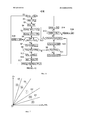
фиг. 6 - последовательность этапов, осуществляемая процессором регулирования спектрометра согласно варианту выполнения;FIG. 6 is a flowchart performed by a spectrometer adjustment processor according to an embodiment;
фиг. 7 - график, определяющий рабочие зоны спектрометра.FIG. 7 is a graph defining the working areas of the spectrometer.
На фиг. 1 показан спектрометр, выполненный, в частности, с возможностью соблюдения специфических требований к датчику, установленному на транспортном средстве или на тепловом двигателе. Спектрометр содержит:In FIG. 1 shows a spectrometer, made in particular with the possibility of observing the specific requirements of a sensor mounted on a vehicle or on a heat engine. The spectrometer contains:
- источник света LS, излучающий световой пучок LB,- a light source LS emitting a light beam LB,
- оптический элемент CLS на основе линз для формирования пучка LB, производимого источником LS,a lens-based optical element CLS for forming the LB beam produced by the LS source,
- измерительную ячейку FLC, в которой анализируемое вещество взаимодействует с пучком LB,- a measuring cell FLC, in which the analyte interacts with the beam LB,
- фильтр длины волны WFL, позволяющий распределять в пространстве различные длины волн пучка LB на выходе ячейки FLC, и- a wavelength filter WFL, allowing to distribute in space various wavelengths of the LB beam at the output of the FLC cell, and
- датчик OPS, который выдает измерения, позволяющие получить спектр света на выходе фильтра WFL.- OPS sensor, which provides measurements that allow you to obtain a spectrum of light at the output of the WFL filter.
Источник света LS охватывает по меньшей мере одну полосу длин волн, называемую полосой «анализа», в которой необходимо осуществлять измерения спектра. Оптический элемент CLS преобразует геометрию пучка и направляет его в измерительную ячейку FLC. Оптический элемент CLS может, например, содержать коллимационную линзу, которая позволяет получить пучок LB с параллельными лучами. Ячейка FLC содержит выходное окно OPW, пропускающее к датчику OPS свет после его взаимодействия с анализируемым веществом. Датчик OPS содержит несколько фоточувствительных элементов (n элементов) и принимает свет, пропускаемый окном OPW через фильтр WFL. Фильтр WFL распределяет длины волн, образующие свет, передаваемый измерительной ячейкой FLC на фоточувствительные элементы датчика OPS, таким образом, чтобы каждая ячейка датчика OPS принимала только сокращенный диапазон длин волн, принадлежащий к полосе длин волн, соответствующей генерируемому спектру. Фильтр WFL может быть, например, фильтром Фабри-Перро или фильтром линейного типа и может обеспечивать пространственный разброс длин волн порядка 2050 нм/мм. Датчик OPS может быть датчиком типа CCD или CMOS и может содержать колодку с набором из 20-200 фоточувствительных элементов.The LS light source spans at least one wavelength band, called the “analysis” band, in which it is necessary to take spectrum measurements. The CLS optical element converts the beam geometry and directs it to the FLC measuring cell. The optical element CLS may, for example, contain a collimation lens, which allows you to get a beam of LB with parallel beams. The FLC cell contains an OPW output window that transmits light to the OPS sensor after it interacts with the analyte. The OPS sensor contains several photosensitive elements (n elements) and receives the light transmitted by the OPW window through the WFL filter. The WFL filter distributes the wavelengths that form the light transmitted by the FLC measuring cell to the photosensitive elements of the OPS sensor, so that each OPS cell receives only a reduced wavelength range belonging to the wavelength band corresponding to the generated spectrum. The WFL filter can be, for example, a Fabry-Perrot filter or a linear filter and can provide a spatial dispersion of wavelengths of the order of 2050 nm / mm. The OPS sensor may be a CCD or CMOS type sensor and may contain a block with a set of 20-200 photosensitive elements.
Источник света LS содержит один или несколько светодиодов (р светодиодов), которые могут быть интегрированы в один электронный компонент, связанный с одной линзой LLD, концентрирующей световые лучи, излучаемые светодиодами, в пучок с небольшим телесным углом. Ток питания или прямое напряжение каждого из светодиодов можно измерять при помощи известных специалисту электронных средств. Источник света LS можно закрепить на оптическом элементе CLS через оптический блок ОВ, через который проходит световой пучок LB, излучаемый источником LS, таким образом, чтобы не захватывать воздух в зоне, через которую проходит пучок. Оптический блок ОВ является прозрачным для анализируемых длин волн и может быть сплошным или может быть полым и заполненным инертной текучей средой. Боковые стороны блока ОВ, через которые не проходит световой пучок, выходящий из источника SL, могут содержать непрозрачное покрытие, чтобы препятствовать утечкам света через эти стороны.The LS light source contains one or more light emitting diodes (p light emitting diodes), which can be integrated into one electronic component connected to a single LLD lens, which concentrates the light rays emitted by the light emitting diodes into a beam with a small solid angle. The supply current or forward voltage of each of the LEDs can be measured using electronic means known to the person skilled in the art. The light source LS can be mounted on the optical element CLS through the optical unit OB, through which the light beam LB emitted by the source LS passes, so as not to trap air in the area through which the beam passes. The optical OB unit is transparent to the analyzed wavelengths and may be continuous or may be hollow and filled with an inert fluid. The sides of the OB unit, through which the light beam exiting from the source SL does not pass, may contain an opaque coating to prevent light leaks through these sides.
Фильтр WFL закреплен на окне OPW таким образом, чтобы не захватывать воздух напрямую или через оптический блок, имеющий те же характеристики, что и описанные ранее для оптического блока ОВ. Точно так же, фильтр WFL закреплен на входном окне датчика OPS таким образом, чтобы не захватывать воздух напрямую или через оптический блок, который может иметь те же характеристики, что и описанные ранее для оптического блока ОВ.The WFL filter is mounted on the OPW window so as not to trap air directly or through an optical unit having the same characteristics as described previously for the optical OB unit. In the same way, the WFL filter is mounted on the input window of the OPS sensor so that it does not capture air directly or through the optical unit, which may have the same characteristics as previously described for the optical OB unit.
Таким образом, спектрометр может быть моноблочным, что облегчает его хранение и манипулирование им в промышленных условиях. Юстировку различных оптических элементов, входящих в состав спектрометра, можно произвести раз и навсегда во время изготовления спектрометра. Отсутствие воздуха в зоне, через которую проходит световой пучок LB, между источником LS и датчиком OPS позволяет также избегать любой возможности конденсации водяного пара в этой зоне, поскольку присутствие водяных капель на пути пучка LB может помешать анализу вещества в измерительной ячейке FLC.Thus, the spectrometer can be monoblock, which facilitates its storage and handling under industrial conditions. The alignment of various optical elements that make up the spectrometer can be made once and for all during the manufacture of the spectrometer. The absence of air in the area through which the LB light beam passes between the LS source and the OPS sensor also avoids any possibility of condensation of water vapor in this area, since the presence of water droplets in the path of the LB beam can interfere with the analysis of the substance in the FLC measuring cell.
Спектрометром управляют при помощи устройства управления и регулирования RPRC, которое регулирует ток питания LCx (где х является целым числом от 1 до р) каждого светодиода, а также время интегрирования ITy (где y является целым числом от 1 до n) каждого фоточувствительного элемента y датчика OPS в зависимости от различных параметров, включая по меньшей мере один из следующих параметров: сила света LFLx светового потока, излучаемого светодиодами источника света LS, температура TPL источника света LS, температура ТРР анализируемого вещества и температура TPS датчика OPS. Время интегрирования ITy фоточувствительного элемента соответствует времени, в течение которого потенциальная яма фоточувствительного элемента остается в состоянии заряда под действием светового потока.The spectrometer is controlled by an RPRC control and regulation device that controls the LCx supply current (where x is an integer from 1 to p) of each LED, as well as the integration time ITy (where y is an integer from 1 to n) of each photosensitive element y of the sensor OPS depending on various parameters, including at least one of the following parameters: luminous intensity LFLx of the light flux emitted by the LEDs of the light source LS, temperature TPL of the light source LS, temperature TPP of the analyte and temperature TPS OPS sensor. The integration time ITy of the photosensitive element corresponds to the time during which the potential well of the photosensitive element remains in a state of charge under the action of the light flux.
Согласно варианту выполнения, силу LFLx светового потока, излучаемого каждым светодиодом источника LS, измеряют при помощи остающихся выключенными светодиодов источника LS (получающих нулевой ток питания), и в данный момент включены только один или несколько светодиодов источника LS. Для генерирования спектра измерения светодиоды источника включают последовательно группами по меньшей мере из одного светодиода, тогда как каждый по меньшей мере из части остающихся выключенными светодиодов источника LS используют как фотодиод для измерения силы света, излучаемого источником LS. После включения группы по меньшей мере из одного светодиода спектр измеряют при помощи фоточувствительных элементов датчика OPS. Когда все светодиоды оказываются включенными по меньшей мере один раз в течение цикла включения светодиодов, полученные спектры комбинируют для получения искомого спектра измерения.According to an embodiment, the strength LFLx of the light flux emitted by each LED of the LS source is measured with the LS source LEDs (receiving zero supply current) remaining off, and only one or more LS source LEDs are currently on. To generate a measurement spectrum, the source LEDs are switched on sequentially in groups of at least one LED, while at least part of the remaining source LEDs that are off are used as a photodiode to measure the intensity of the light emitted by the source LS. After switching on a group of at least one LED, the spectrum is measured using the photosensitive elements of the OPS sensor. When all the LEDs turn on at least once during the LED turn-on cycle, the obtained spectra are combined to obtain the desired measurement spectrum.
Согласно варианту выполнения, устройство регулирования RPRC осуществляет регулирование в режиме замкнутого контура одновременно тока питания LCx светодиодов источника LS и времени интегрирования ITy фоточувствительных элементов датчика OPS. Когда время интегрирования ITy достигает предельного значения, но при этом на выходе датчика OPS не получают удовлетворительного сигнала (в интервале между двумя предельными значениями), производят коррекцию силы или напряжения тока питания LCx источника света. Это регулирование предназначено для стабилизации сигнала, принимаемого каждым из фоточувствительных элементов датчика, а также для минимизации влияния внешних факторов на само анализируемое вещество, таких как колебания окружающей температуры или старение светодиодов источника LS. Это регулирование позволяет спектрометру работать в очень широком температурном диапазоне, сохраняя при этом относительно постоянное во времени и однородное соотношение сигнал/шум в зависимости от длины волны и, следовательно, по существу постоянную чувствительность измерения.According to an embodiment, the RPRC regulator controls both the closed-loop power supply current LCx of the LS source LEDs and the integration time ITy of the photosensitive elements of the OPS sensor. When the integration time ITy reaches the limit value, but the OPS sensor does not receive a satisfactory signal (in the interval between the two limit values), the power supply voltage or voltage LCx of the light source is corrected. This regulation is intended to stabilize the signal received by each of the photosensitive elements of the sensor, as well as to minimize the influence of external factors on the analyte itself, such as fluctuations in ambient temperature or aging of the LEDs of the LS source. This regulation allows the spectrometer to operate in a very wide temperature range, while maintaining a relatively constant in time and uniform signal to noise ratio depending on the wavelength and, therefore, essentially constant measurement sensitivity.
Время интегрирования датчика OPS можно корректировать индивидуально для каждого фоточувствительного элемента датчика OPS, например, выбирая в качестве общего времени интегрирования минимальное из значений времени интегрирования ITy, определенных для каждого из элементов y.The integration time of the OPS sensor can be individually adjusted for each photosensitive element of the OPS sensor, for example, by choosing as the total integration time the minimum of the values of the integration time ITy defined for each of the elements y.
Устройство регулирования RPRC получает измерение силы света MSy для каждого элемента y датчика OPS и может выдавать измерения MSCy, скорректированные в зависимости от различных параметров, таких как температура ТРР анализируемого вещества и/или температура TPS датчика OPS.The RPRC control device obtains a light intensity measurement MSy for each element y of the OPS sensor and can provide MSCy measurements adjusted depending on various parameters, such as the TPP temperature of the analyte and / or the TPS temperature of the OPS sensor.
На фиг. 2 показана электронная схема управления LSCC источником света LS согласно варианту выполнения. Как показано на фиг. 2, схема LSCC подключена к источнику света LS и соединена с устройством регулирования RPRC через модуль преобразования CVM, содержащий несколько аналого-цифровых преобразователей и несколько цифро-аналоговых преобразователей. Источник света LS содержит несколько светодиодов LD1, LD2, LD3, LD4. Схема LSCC содержит схемы регулирования тока REG1, REG2, REG3, REG4, усилители с регулируемым коэффициентом усиления АН, А12, А13, А14, А21, А22, А23, А24, переключатели СМ1, СМ2, CM3, СМ4 и резисторы R1, R2, R3, R4. Катод каждого светодиода LD1-LD4 подключен к массе. Анод каждого светодиода LD1-LD4 соединен через соответствующий переключатель СМ1-СМ4 с входом одного из усилителей А21-А24 и с выходом одного из усилителей А11-А14. Выход каждого из усилителей А21-А24 соединен с входом аналого-цифрового преобразователя модуля преобразования CVM, который передает в устройство RPRC цифровые значения измерения силы света LFL1, LFL2, LFL3, LFL4, поступающие от светодиодов LD1-LD4. Каждый усилитель А11-А14 соединен с источником напряжения питания AV через один из резисторов R1-R4. Каждый усилитель А11-А14 принимает на входе управления коэффициентом усиления сигнал управления током АС1-АС4, выдаваемый одним из регуляторов REG1-REG4. Каждый регулятор REG1-REG4 производит измерение тока питания I1-I4 светодиода LD1-LD4, с которым он соединен. Каждый регулятор REG1-REG4 получает заданное значение тока LC1-LC2, выдаваемое в цифровом виде устройством регулирования RPRC и преобразованное цифро-аналоговым преобразователем модуля CVM. Каждый регулятор REG1-REG4 регулирует один из сигналов управления током АС1-АС4 в зависимости от заданного значения тока LC1-LC4, которое он получает в зависимости силы тока I1-I4, измеряемой им на выходе усилителя А1-А4, коэффициентом усиления которого он управляет, таким образом, чтобы измеряемый ток I1-I4 соответствовал заданному значению тока LC1-LC4.In FIG. 2 shows an electronic control circuit LSCC of the LS light source according to an embodiment. As shown in FIG. 2, the LSCC circuit is connected to the LS light source and connected to the RPRC control device through a CVM conversion module containing several analog-to-digital converters and several digital-to-analog converters. LS light source contains several LEDs LD1, LD2, LD3, LD4. The LSCC circuit contains current control circuits REG1, REG2, REG3, REG4, amplifiers with adjustable gain AN, A12, A13, A14, A21, A22, A23, A24, switches CM1, CM2, CM3, CM4 and resistors R1, R2, R3 , R4. The cathode of each LD1-LD4 LED is connected to ground. The anode of each LED LD1-LD4 is connected through the corresponding switch CM1-CM4 to the input of one of the amplifiers A21-A24 and to the output of one of the amplifiers A11-A14. The output of each of the amplifiers A21-A24 is connected to the input of the analog-to-digital converter of the CVM conversion module, which transmits to the RPRC device the digital values of the light intensity measurement LFL1, LFL2, LFL3, LFL4 coming from the LD1-LD4 LEDs. Each amplifier A11-A14 is connected to an AV voltage source through one of the resistors R1-R4. Each amplifier A11-A14 receives at the gain control input a current control signal AC1-AC4, issued by one of the REG1-REG4 controllers. Each REG1-REG4 regulator measures the supply current I1-I4 of the LD1-LD4 LED with which it is connected. Each REG1-REG4 regulator receives a given current value LC1-LC2, digitally output by the RPRC control unit and converted by a CVM digital-to-analog converter. Each REG1-REG4 regulator regulates one of the AC1-AC4 current control signals depending on the set value of the current LC1-LC4, which it receives depending on the current strength I1-I4, measured by it at the output of the amplifier A1-A4, the gain of which it controls, so that the measured current I1-I4 corresponds to the set current value LC1-LC4.
Схема LSCC или источник тока LS может содержать температурный датчик TSS для измерения температуры источника LS. Этот температурный датчик TSS подключен к аналого-цифровому преобразователю модуля CVM, который выдает в устройство RPRC цифровые значения измерения температуры TPL источника LS.The LSCC circuit or LS current source may include a TSS temperature sensor for measuring the temperature of the LS source. This TSS temperature sensor is connected to the CVM analog-to-digital converter, which provides the RPRC with digital temperature measurements TPL of the LS source.
Каждый регулятор REG1-REG4 может передавать измерение тока I1-I4 в аналого-цифровой преобразователь модуля CVM, который, в свою очередь, передает соответствующее цифровое значение в устройство RPRC. Точно так же, анод каждого светодиода LD1-LD4 может быть подключен к аналого-цифровому преобразователю модуля CVM, который выдает в устройство RPRC цифровое значение, характеризующее напряжение V1-V4 анода светодиода. Кроме того, светодиоды LD1-LD4 могут быть выполнены на одной полупроводниковой подложке и могут быть интегрированы в один компонент. Устройство RPRC может содержать соединитель для своего подключения через последовательную или параллельную шину DTB к вычислительному устройству и для передачи спектров измерения MR (1…n) и рабочего состояния OMD, а также, в случае необходимости других сигналов, например, связанных с измерениями, осуществляемыми на спектрометре.Each REG1-REG4 regulator can transmit the current measurement I1-I4 to the CVM analog-to-digital converter, which in turn transmits the corresponding digital value to the RPRC device. In the same way, the anode of each LED LD1-LD4 can be connected to the CVM analog-to-digital converter, which provides a digital value to the RPRC device that characterizes the voltage V1-V4 of the LED anode. In addition, the LD1-LD4 LEDs can be made on a single semiconductor substrate and can be integrated into a single component. An RPRC device may include a connector for connecting via a serial or parallel DTB to a computing device and for transmitting MR (1 ... n) measurement spectra and OMD operating status, as well as, if necessary, other signals, for example, related to measurements carried out on spectrometer.
В примере, представленном на фиг. 2, источник света LS содержит четыре светодиода LD1-LD4. Каждый светодиод может излучать свет со спектром в виде асимметричной кривой Гаусса. Так, на фиг. 3А показаны спектры излучения светодиодов LD1-LD4 в виде кривых С1-С4 изменения силы излучаемого света в зависимости от длины волны. Кривые С1-С4, показанные на фиг. 3А, были получены при постоянном значении тока питания, идентичном для всех светодиодов LD1-LD4. Значения силы света, показанные на оси ординат, являются нормализованными значениями. В примере, представленном на фиг. 3А, кривая С1 спектра светодиода LD1 имеет максимум силы света в значении 1 при длине волны, примерно равной 850 нм. Кривая С2 спектра светодиода LD2 показывает максимум силы света в значении около 0.92 при длине волны, примерно равной 890 нм. Кривая С3 спектра светодиода LD3 показывает максимум силы света в значении около 0.41 при длине волны, примерно равной 940 нм. Кривая С4 спектра светодиода LD4 показывает максимум силы света в значении около 0.22 при длине волны, примерно равной 970 нм. На фиг. 3 можно заметить, что, чем больше длина волны максимальной силы света, излучаемого светодиодом LD1-LD4, тем меньше эта сила света.In the example of FIG. 2, the LS light source contains four LEDs LD1-LD4. Each LED can emit light with a spectrum in the form of an asymmetric Gaussian curve. So in FIG. 3A shows the emission spectra of LEDs LD1-LD4 in the form of curves C1-C4 of a change in the intensity of the emitted light depending on the wavelength. Curves C1-C4 shown in FIG. 3A were obtained at a constant supply current value identical for all LD1-LD4 LEDs. The luminous values shown on the y-axis are normalized values. In the example of FIG. 3A, the curve C1 of the spectrum of the LD1 LED has a maximum luminous intensity of 1 at a wavelength of approximately 850 nm. The C2 curve of the spectrum of the LD2 LED shows the maximum luminous intensity at a value of about 0.92 at a wavelength of approximately 890 nm. The curve C3 of the spectrum of the LD3 LED shows the maximum luminous intensity at a value of about 0.41 at a wavelength of approximately 940 nm. The curve C4 of the spectrum of the LD4 LED shows the maximum luminous intensity at a value of about 0.22 at a wavelength of approximately equal to 970 nm. In FIG. 3 you can see that the longer the wavelength of the maximum light intensity emitted by the LD1-LD4 LED, the lower this light intensity.
На фиг. 3B в виде кривых C1'С4' изменения силы излучаемого света в зависимости от длины волны показаны спектры излучения светодиодов LD1-LD4 после коррекции тока питания LC1-LC4 каждого светодиода LD1-LD4 устройством регулирования RPRC. Все показанные на фиг. 3B кривые С1'-С4' имеют нормализованное максимальное значение силы света, равное 1. На фиг. 3B также в виде кривой CR показан комбинированный спектр излучения, излучаемый, когда диоды LD1-LD4 включены одновременно при скорректированном токе питания LC1-LC4. В примере, представленном на фиг. 3B, комбинированный спектр излучения источника света растянут примерно от 840 до 980 нм. Следует отметить, что цифровые значения на фиг. 3А и 3B представлены в качестве примера и могут меняться, в частности, в зависимости от условий изготовления светодиодов.In FIG. 3B, the emission spectra of the emitted light versus wavelength are shown in the form of curves C1'C4 ', the emission spectra of the LD1-LD4 LEDs after the correction of the supply current LC1-LC4 of each LD1-LD4 LED by the RPRC control device are shown. All shown in FIG. 3B, curves C1'-C4 'have a normalized maximum luminous intensity value of 1. In FIG. 3B also shows, in the form of a CR curve, the combined emission spectrum emitted when the diodes LD1-LD4 are turned on simultaneously with the corrected supply current LC1-LC4. In the example of FIG. 3B, the combined emission spectrum of the light source is stretched from about 840 to 980 nm. It should be noted that the numerical values in FIG. 3A and 3B are presented as an example and may vary, in particular, depending on the manufacturing conditions of the LEDs.
На фиг. 4 показаны спектры чувствительности светодиодов LD1-LD4 в виде кривых C11-С14 изменения силы генерируемого тока в зависимости от длины волны. Эти спектры были получены путем измерения силы тока, генерируемого каждым светодиодом LD1-LD4, когда его светоизлучающая поверхность экспонируется световым потоком 1 мВт/см2 и в отсутствие тока питания. Как показано на фиг. 4, ток, генерируемый светодиодами LD1-LD4, достигает нескольких десятых мкА, когда на светодиод действует световой поток в 1 мВт/см2.In FIG. Figure 4 shows the sensitivity spectra of LEDs LD1-LD4 in the form of curves C11-C14 of the change in the strength of the generated current depending on the wavelength. These spectra were obtained by measuring the current generated by each LD1-LD4 LED when its light-emitting surface is exposed to a luminous flux of 1 mW / cm 2 and in the absence of a supply current. As shown in FIG. 4, the current generated by the LD1-LD4 LEDs reaches several tenths of a microA when the light flux of 1 mW / cm 2 acts on the LED.
Согласно варианту выполнения, переключателями СМ1-СМ4 управляют таким образом, чтобы включать только один из светодиодов LD1-LD4 за один раз, при этом все другие светодиоды выключены (не получают тока питания) и работают как фотодиоды. Выключенные светодиоды выдают, каждый, измерение LFL1-LFL4 (три измерения из четырех возможных) силы света, генерируемого включенным светодиодом, в их соответствующем спектре чувствительности. Как только датчик OPS выдает спектр измерения при включенном светодиоде, этот светодиод выключают и включают другой светодиод и так далее для всех других светодиодов. Спектры, полученные при помощи каждого из включенных светодиодов, после этого комбинируют соответствующим образом для получения результирующего спектра MR(1…n).According to an embodiment, the switches CM1-CM4 are controlled in such a way as to turn on only one of the LEDs LD1-LD4 at a time, while all other LEDs are off (do not receive a supply current) and operate as photodiodes. The off LEDs give each LFL1-LFL4 measurement (three measurements out of four possible) the light intensity generated by the on LED in their corresponding sensitivity spectrum. As soon as the OPS sensor gives a measurement spectrum when the LED is on, this LED is turned off and another LED is turned on and so on for all other LEDs. The spectra obtained with each of the LEDs turned on are then combined accordingly to obtain the resulting MR spectrum (1 ... n).
Следует отметить, что, поскольку одновременно включен только один светодиод LD1-LD4, схему LSCC можно упростить, сохраняя только один из регуляторов REG1-REG4 и только один из усилителей А11-А14. Каждый из переключателей СМ1-СМ4 содержит в этом случае один контакт, подключенный к выходу оставшегося усилителя А11-А14, один контакт, подключенный к аноду светодиода LD1-LD4, и один контакт, подключенный к входу одного из усилителей А21-А24.It should be noted that since only one LD1-LD4 LED is on at a time, the LSCC circuit can be simplified by keeping only one of the REG1-REG4 controllers and only one of the A11-A14 amplifiers. Each of the switches CM1-CM4 in this case contains one contact connected to the output of the remaining amplifier A11-A14, one contact connected to the anode of the LD1-LD4 LED, and one contact connected to the input of one of the amplifiers A21-A24.
Переключатели СМ1-СМ4 можно исключить, если регуляторы REG1-REG4 (или оставшийся регулятор) поддерживают при плавающем потенциале свой вход тока I1-I4 и усилители А11-А13 (или оставшийся усилитель) поддерживают при плавающем потенциале свой выход усиленного тока.The switches СМ1-СМ4 can be excluded if the REG1-REG4 regulators (or the remaining regulator) support their current input I1-I4 at a floating potential and the A11-A13 amplifiers (or the remaining amplifier) support their amplified current output at a floating potential.
Кроме того, результирующий спектр излучения (кривая CR) может быть не полностью перекрыт комбинированным спектром чувствительности светодиодов LD1-LD4. В этом случае можно использовать фотодиод, измеряющий напрямую силу света, излучаемого каждым включенным светодиодом. Этот фотодиод может быть, например, интегрирован в источник LS.In addition, the resulting emission spectrum (CR curve) may not be completely covered by the combined sensitivity spectrum of LD1-LD4 LEDs. In this case, you can use a photodiode that directly measures the intensity of the light emitted by each LED. This photodiode can, for example, be integrated into the LS source.
На фиг. 5 представлена электронная схема управления LSC1 источником света LSI согласно варианту выполнения. На фиг. 5 источник света LSI отличается от источника света LS тем, что содержит фотодиод PHD. Схема LSC1 отличается от схемы LSCC тем, что содержит дополнительный усилитель А20, получающий выходной сигнал фотодиода PHD и выдающий электрический сигнал измерения силы света LFL0 в аналого-цифровой преобразователь модуля CVM преобразования. Устройство RPRC регулирования использует цифровое значение измерения LFL0 вместе с цифровыми значениями измерений LFL1-LFL4 для регулирования силы света, излучаемого источником LS1. Пример спектра чувствительности фотодиода показан на фиг. 4. Так, на фиг. 4 показана также кривая CP чувствительности фотодиода, который можно использовать в схеме, показанной на фиг. 5. Действительно, кривая CP является по существу постоянной (меняется от 0.5 до 0.6) в полосе длин волн анализа, примерно между 840 и 980 нм.In FIG. 5 is an electronic control circuit LSC1 of an LSI light source according to an embodiment. In FIG. 5, the LSI light source differs from the LS light source in that it contains a PHD photodiode. The LSC1 circuit differs from the LSCC circuit in that it contains an additional amplifier A20 that receives the output signal of the PHD photodiode and generates an electric signal for measuring the light intensity LFL0 into an analog-to-digital converter of the CVM conversion module. The RPRC control device uses the digital measurement value LFL0 together with the digital measurement values LFL1-LFL4 to control the intensity of the light emitted by the source LS1. An example of the sensitivity spectrum of a photodiode is shown in FIG. 4. So, in FIG. 4 also shows the sensitivity curve CP of the photodiode, which can be used in the circuit shown in FIG. 5. Indeed, the CP curve is essentially constant (varies from 0.5 to 0.6) in the analysis wavelength band, approximately between 840 and 980 nm.
На фиг. 6 представлена последовательность этапов, которую может осуществлять устройство RPRC регулирования. Показанная на фиг. 6 последовательность этапов включает в себя этапы S1-S18. На этапе S1 устройство RPRC устанавливает по заданному значению LCx ток питания (сила тока или напряжение) светодиода LDx источника света LS (при этом х последовательно равно 1, 2, 3 и 4 в примере на фиг. 2). Значение LCx является заранее определенным первоначальным значением или значением, ранее примененным для светодиода LDx. На следующих этапах S2 и S3 устройство RPRC получает измерения силы света LFLz (при этом z отличается от х) от не включенных светодиодов LD1-LD4, и, в случае необходимости, измерение силы света LFL0, поступающее от фотодиода, и измерение температуры TPL, поступающее от датчика TSS. На следующих этапах S4 и S5 устройство RPRC посредством равнения определяет, согласуются ли принятые измерения силы света LFLz и температуры TPL между собой и с током LCx, подаваемым на светодиод LDx. Эти этапы можно осуществлять при помощи номограмм изменения силы света, излучаемого светодиодом LDx, в зависимости от его тока питания и от его температуры. Сравнения, производимые на этапах S4 и S5, позволяют осуществить автоматическую диагностику спектрометра на этапе S6. Так, если сравнения на этапах S4 и S5 выявляют нарушение в работе и если спектрометр находится в нормальном режиме работы OMD, спектрометр переходит в режим DG с ухудшенными параметрами работы OMD. Если сравнения на этапах S4 и S5 выявляют нарушение в работе и если спектрометр находится в режиме с ухудшенными параметрами работы DG, спектрометр переходит на этапе S18 в режим неисправности DF, в котором он больше не может работать. Если сравнения на этапах S4 и S5 не показывают нарушений в работе, устройство RPRC осуществляет следующие этапы S7 и S8. На этапе S7 устройство RPRC определяет оптимальное время интегрирования ITy каждого фоточувствительного элемента y датчика OPS при помощи функции f1, применяемой к значениям силы света LFLz, измеренным на этапе S2. Функцию f1 можно определить при помощи номограмм, дающих оптимальное время интегрирования каждого элемента y датчика OPS в зависимости от измерений силы излучаемого света LFLz, поступающих от каждого светодиода, работающего в режиме фотодиода. На этапе S8 устройство RPRC сравнивает для каждого элемента y полученное время интегрирования ITy с минимальным ITmy и максимальным ITMy значениями, определенными для элемента y. Если время интегрирования ITy находится в интервале между минимальным и максимальным значениями ITmy, ITMy для каждого элемента y, устройство RPRC осуществляет этапы S15-S17, затем возвращается на этап S1 для осуществления новой фазы регулирования, в противном случае оно осуществляет этап S9.In FIG. 6 shows a sequence of steps that an RPRC control device can carry out. Shown in FIG. 6, the flow of steps includes steps S1-S18. At step S1, the RPRC device sets the supply current (current or voltage) of the LED LDx of the light source LS (at the same time, x is 1, 2, 3, and 4 in the example in Fig. 2) at a given value LCx. The LCx value is a predetermined initial value or a value previously applied to the LDx LED. In the following steps S2 and S3, the RPRC device receives the LFLz light intensity measurements (in this case z differs from x) from the LD1-LD4 LEDs not turned on, and, if necessary, the LFL0 light intensity measurement received from the photodiode and the TPL temperature measurement received from the TSS sensor. In the next steps S4 and S5, the RPRC device determines by means of equalization whether the received measurements of the light intensity LFLz and the temperature TPL are consistent with each other and with the current LCx supplied to the LDx LED. These steps can be carried out using nomograms of the change in the intensity of the light emitted by the LDx LED, depending on its supply current and its temperature. The comparisons made in steps S4 and S5 allow automatic diagnostics of the spectrometer in step S6. So, if the comparisons in steps S4 and S5 reveal a malfunction and if the spectrometer is in normal OMD operation, the spectrometer enters DG mode with OMD performance degraded. If the comparisons in steps S4 and S5 reveal a malfunction and if the spectrometer is in a mode with degraded DG operation parameters, the spectrometer goes to step D18 in the DF fault mode, in which it can no longer operate. If the comparisons in steps S4 and S5 do not show abnormalities, the RPRC device performs the following steps S7 and S8. In step S7, the RPRC device determines the optimal integration time ITy of each photosensitive element y of the OPS sensor using the function f1 applied to the light intensities LFLz measured in step S2. The function f1 can be determined using nomograms giving the optimal integration time of each element y of the OPS sensor depending on the measurements of the emitted light LFLz coming from each LED operating in the photodiode mode. In step S8, the RPRC device compares for each element y the obtained integration time ITy with the minimum ITmy and maximum ITMy values determined for the element y. If the integration time ITy is between the minimum and maximum values ITmy, ITMy for each element y, the RPRC performs steps S15-S17, then returns to step S1 to implement a new control phase, otherwise it performs step S9.
На этапе S9 устройство RPRC сравнивает оптимальное время интегрирования ITy с минимальным временем интегрирования ITmy для каждого элемента y, по которому тест на этапе S8 не был проверен. Если время интегрирования ITy меньше времени интегрирования ITmy для всех или части элементов у датчика OPS, модуль RPRC осуществляет этап S10, затем S12, в противном случае (когда время интегрирования ITy превышает максимальное время интегрирования ITMy для всех или для части элементов y) оно осуществляет этапы S11 и S12. На этапе S10 устройство RPRC уменьшает на один шаг STP ток питания LCx светодиода LDx. На этапе S11 устройство RPRC инкрементирует ток питания LCx светодиода LDx на шаг STP. На этапе S12 устройство RPRC определяет, находится ли новый ток питания LCx, полученный на этапе S10 или S11, в интервале между минимальным LCmx и максимальным LCMx значениями, определенными для светодиода LDx. Если это так, устройство RPRC возвращается на этап S1 для осуществления новой фазы регулирования. В противном случае устройство RPRC осуществляет этап S13, на котором оно тестирует режим работы OMD спектрометра. Если режим OMD является нормальным NL, устройство RPRC осуществляет этап S14, на котором режим работы OMD переходит в режим DG с ухудшенными параметрами. Если на этапе S13 режим OMD является режим DG с ухудшенными параметрами, устройство RPRC осуществляет этап S18, на котором режим OMD переходит в режим неисправности DF.In step S9, the RPRC device compares the optimal integration time ITy with the minimum integration time ITmy for each element y, for which the test in step S8 has not been verified. If the ITy integration time is less than the ITmy integration time for all or part of the elements of the OPS sensor, the RPRC performs step S10, then S12, otherwise (when the ITy integration time exceeds the maximum ITMy integration time for all or for some of the elements y) it performs the steps S11 and S12. In step S10, the RPRC device reduces the supply current LCx of the LDx LED by one step STP. In step S11, the RPRC increments the power supply current LCx of the LDx LED by step STP. In step S12, the RPRC device determines whether the new LCx supply current obtained in step S10 or S11 is between the minimum LCmx and the maximum LCMx values determined for the LDx LED. If so, the RPRC device returns to step S1 to implement a new control phase. Otherwise, the RPRC device performs step S13, in which it tests the operation mode of the OMD spectrometer. If the OMD mode is normal NL, the RPRC device performs step S14, in which the OMD operation mode switches to the DG mode with degraded parameters. If in step S13, the OMD mode is a DG mode with degraded parameters, the RPRC device performs step S18, in which the OMD mode switches to the DF fault mode.
Таким образом, на этапах S10 и S11, если оптимальное время интегрирования ITy, определенное по меньшей мере для одного фоточувствительного элемента y, находится за пределами минимального и максимального порогов ITmy и ITMy, к току питания LCx светодиода LDx добавляют положительный или отрицательный шаг STP определенной амплитуды (положительный, если оптимальное время интегрирования ITy превышает максимальный порог ITMy, и отрицательный, если это время интегрирования меньше минимального порога ITmy). При этом на этапах S1-S7 опять определяют новое оптимальное время интегрирования ITy в зависимости от нового тока LCx. Этапы S1-S12 повторяют, пока оптимальное время интегрирования ITy остается за пределами порогов ITmy и ITMy и пока ток LCx остается в интервале между порогами LCmx и LCMx.Thus, in steps S10 and S11, if the optimal integration time ITy determined for at least one photosensitive element y is outside the minimum and maximum thresholds ITmy and ITMy, a positive or negative STP step of a certain amplitude is added to the supply current LCx of the LDx LED (positive if the optimal integration time ITy exceeds the maximum threshold ITMy, and negative if this integration time is less than the minimum threshold ITmy). Moreover, in steps S1-S7, a new optimal integration time ITy is again determined depending on the new LCx current. Steps S1-S12 are repeated until the optimal integration time ITy remains outside the thresholds ITmy and ITMy and as long as the current LCx remains between the thresholds LCmx and LCMx.
На этапе S15 устройство RPRC устанавливает время интегрирования каждого элемента y датчика OPS по его оптимальному времени интегрирования ITy, определенному на этапе S7. На этапе S16 устройство RPRC считывает измерение MSxy, выдаваемое каждым элементом y при включенном светодиоде LDx, а также, в случае необходимости, измерение температуры TP анализируемого вещества в измерительной ячейке FLC (ТРР) и/или измерение температуры датчика OPS (TPS) и/или измерение температуры источника LS (TPL). На этапе S17 устройство RPRC применяет поправку к каждому измерению MSxy при помощи функции f2 и выдает скорректированное измерение MSCxy для каждого элемента y. Функцию f2 применяют к измеренной температуре TP (или к измеренным температурам) на этапе S16.In step S15, the RPRC device sets the integration time of each element y of the OPS sensor according to its optimal integration time ITy determined in step S7. In step S16, the RPRC device reads the MSxy measurement issued by each element y when the LDx LED is on, as well as, if necessary, measuring the temperature TP of the analyte in the FLC measuring cell (TPP) and / or measuring the temperature of the OPS sensor (TPS) and / or LS source temperature measurement (TPL). In step S17, the RPRC device applies the correction to each MSxy measurement using the function f2 and provides an adjusted MSCxy measurement for each element y. The function f2 is applied to the measured temperature TP (or to the measured temperatures) in step S16.
Таким образом, последовательность этапов S1-S18 позволяет получить скорректированный спектр MSCx(1…n) для каждого светодиода LDx. Последовательность этапов S1-S15 осуществляют для каждого светодиода LDx источника LS, чтобы получить по меньшей мере один спектр MSCx(1…n) для каждого светодиода LDx. После нормализации спектров, полученных для каждого светодиода, вычисляют результирующий спектр MR(1…n) путем сложения спектров, полученных при каждом включенном светодиоде LDx, с коэффициентом взвешивания Рху, определенном для каждого светодиода LDx и каждого элемента y датчика OPS:Thus, the sequence of steps S1-S18 allows you to get the corrected spectrum MSCx (1 ... n) for each LED LDx. The sequence of steps S1-S15 is carried out for each LED LDx of the LS source to obtain at least one MSCx spectrum (1 ... n) for each LDx LED. After normalizing the spectra obtained for each LED, the resulting MR spectrum (1 ... n) is calculated by adding the spectra obtained with each LDx LED turned on with the weighting coefficient Pkh determined for each LDx LED and each element y of the OPS sensor:

Коэффициенты взвешивания Pxy можно корректировать для придания большего значения полезному сигналу в результирующем спектре. Иначе говоря, сигналы элементов y, измеряющих наибольшие необработанные сигналы и, следовательно, выдающие наиболее надежную информацию (высокое отношение сигнала к шуму), связывают с наибольшим коэффициентом взвешивания Pxy. Коэффициенты взвешивания Pxy определяют в течение фазы калибровки, и они зависят от температуры TPL источника LS.The weighting factors Pxy can be adjusted to give a greater value to the useful signal in the resulting spectrum. In other words, the signals of the elements y, which measure the largest raw signals and, therefore, produce the most reliable information (high signal-to-noise ratio), are associated with the highest weighting coefficient Pxy. The weighting factors Pxy are determined during the calibration phase, and they depend on the temperature TPL of the source LS.
Кроме того, для полученного результирующего спектра MR(1…n) можно вычислить среднее значение при помощи нескольких других последовательно полученных спектров, чтобы получить спектр, который может использовать устройство регулирования рабочих параметров теплового двигателя. Число спектров MR(1…n), используемых для вычисления среднего спектра, может увеличиваться при переходе от нормального NL режима работы OMD к режиму DG с ухудшенными параметрами. Числе полученных спектров, усредняемых в нормальном режиме, может составлять примерно от 5 до 20 и в аварийном режиме около 100.In addition, for the resulting resulting spectrum MR (1 ... n), the average value can be calculated using several other sequentially obtained spectra to obtain a spectrum that can be used by the device for controlling the operating parameters of the heat engine. The number of MR spectra (1 ... n) used to calculate the average spectrum can increase with the transition from the normal NL OMD operating mode to the DG mode with degraded parameters. The number of spectra obtained, averaged in normal mode, can be from about 5 to 20 and in emergency mode, about 100.
Необходимо отметить, что время интегрирования ITy всех фоточувствительных элементов у датчика OPS можно зафиксировать на этапе S15 по наименьшему времени интегрирования, определенному на этапе S7 для каждого элемента y.It should be noted that the integration time ITy of all the photosensitive elements of the OPS sensor can be fixed in step S15 by the smallest integration time determined in step S7 for each element y.
На этапах S4, S5, S6, S12, S13, S14 и S18 устройство RPRC осуществляет автоматическую диагностику спектрометра, различая при этом три режима работы OMD спектрометра: нормальный NL режим работы, при котором спектрометр выдает применимые измерения, режим DG с ухудшенными параметрами работы, при котором спектрометр продолжает выдавать применимые измерения, но в аномальных условиях, и режим неисправности DF, при котором спектрометр считается неисправным и не может больше выдавать применимые измерения. В режиме DG с ухудшенными параметрами время для измерения намного увеличивается или же степень надежности измерений снижается (это зависит от выбора пользователя). Спектрометр считается неисправным (режим OMD=DF), например, если измерения силы света LFLz, поступающие от выключенных светодиодов LD1-LD4, не соответствуют току LCx, подаваемому на включенный светодиод, или температуре TPS источника LS. Устройство RPRC может выдать сигнал автоматической диагностики, указывающий на режим работы OMD спектрометра. Этот сигнал может быть передан, например, в бортовой компьютер транспортного средства, на котором установлен спектрометр.At steps S4, S5, S6, S12, S13, S14 and S18, the RPRC device performs automatic diagnostics of the spectrometer, distinguishing between three modes of operation of the OMD spectrometer: normal NL operating mode, in which the spectrometer produces applicable measurements, DG mode with degraded operating parameters, in which the spectrometer continues to produce applicable measurements, but under abnormal conditions, and the fault mode DF, in which the spectrometer is considered to be faulty and can no longer produce applicable measurements. In DG mode with degraded parameters, the measurement time is much longer or the degree of measurement reliability is reduced (this depends on the user's choice). The spectrometer is considered to be faulty (mode OMD = DF), for example, if the light intensity measurements LFLz received from the off LEDs LD1-LD4 do not correspond to the current LCx supplied to the switched on LED or the temperature TPS of the LS source. The RPRC device may issue an automatic diagnostic signal indicating the operating mode of the OMD spectrometer. This signal can be transmitted, for example, to the on-board computer of the vehicle on which the spectrometer is mounted.
На фиг. 7 показан график заданного значения тока LCx (ось ординат), подаваемого на светодиод LDx источника LS, в зависимости от силы света LFLz или от температуры TPL источника LS (ось абсцисс). Этот график отображает четыре прямые D1, D2, D3, D4, проходящие через начало О графика. Прямые D1 и D2 ограничивают между собой зону 1 работы, соответствующую нормальному NL режиму работы, при котором измеренные ток LCx, подаваемый на светодиод LDx источника LS, температура TPL источника и/или сила света LFLz имеют нормальные значения (не слишком низкие и не слишком высокие). Ось ординат и прямая D3 ограничивают между собой зону 3а. Ось абсцисс и прямая D2 D3 ограничивают между собой зону 3b. Зоны 3а и 3b соответствуют режиму неисправности DF, в котором ток LCx, подаваемый на светодиод LDx источника света, является сильным, а сила света, выдаваемая источником, является аномально малой, или в котором ток, подаваемый на светодиод LDx, является слабым, и температура TPL источника является аномально высокой. Между зоной 1 и зонами 3а и 3b находятся зоны 2а и 2b, соответствующие режиму DG с ухудшенными параметрами работы.In FIG. Figure 7 shows a graph of the set value of the current LCx (ordinate axis) supplied to the LED LDx of the LS source, depending on the light intensity LFLz or on the temperature TPL of the LS source (abscissa). This graph displays the four lines D1, D2, D3, D4 passing through the beginning of the O graph. Straight lines D1 and D2 limit between themselves the operating
Минимальное LCmx и максимальное LCMx значения тока питания каждого светодиода LDx получают в результате тестов, осуществляемых во время фазы калибровки для определения идеального диапазона работы каждого из светодиодов источника LS. Максимальное значение LCMx определяют, чтобы не ускорять старение светодиода. Минимальное значение LCmx можно выбирать таким образом, чтобы обеспечивать повторяемость и стабильность излучаемого светодиодом светового потока.The minimum LCmx and maximum LCMx values of the supply current of each LDx LED are obtained as a result of tests carried out during the calibration phase to determine the ideal operating range for each of the LS source LEDs. The maximum value of LCMx is determined so as not to accelerate the aging of the LED. The minimum LCmx value can be chosen in such a way as to ensure repeatability and stability of the light flux emitted by the LED.
Минимальное ITmy и максимальное ITMy значения времени интегрирования каждого элемента y датчика OPS тоже определяют в ходе фазы калибровки при помощи тестов, позволяющих определить идеальный диапазон работы фоточувствительных элементов y датчика OPS, рассматриваемых отдельно или в совокупности. Максимальное значение ITMy определяют, чтобы избегать насыщения фоточувствительного элемента y. Минимальное значение ITmy определяют для получения стабильного и повторяемого сигнала, соблюдая вместе с тем предварительно определенное минимальное целевое значение соотношения сигнал/шум.The minimum ITmy and maximum ITMy integration time values of each element y of the OPS sensor are also determined during the calibration phase using tests to determine the ideal range of operation of the photosensitive elements y of the OPS sensor, considered separately or in combination. The maximum ITMy value is determined to avoid saturation of the photosensitive element y. The minimum ITmy value is determined to obtain a stable and repeatable signal, while at the same time observing the predetermined minimum target signal-to-noise ratio.
Точно так же, функции f1 и f2, используемые на этапах S7 и S17, можно определять во время фазы калибровки. Так, функцию f1, дающую оптимальное время интегрирования ITy каждого элемента y датчика OPS в зависимости от значений силы света LFLz, измеряемого не включенными светодиодами LD1-LD4, можно определить, используя одно или несколько текучих или твердых контрольных веществ, на которых осуществляют ряд тестов. Для каждого из контрольных веществ и для каждого светодиода LDx изменяют заданное значение тока питания LCx светодиода LDx и сохраняют в памяти значения силы света LFLz, измеренные выключенными светодиодами LD1-LD4 и возможным фотодиодом PHD. Для каждого значения измерения силы света LFLz и каждого элемента y выявляют оптимальное время интегрирования ITy, позволяющее получать стабильный и постоянный световой поток, измеряемый элементом y, то есть поток, по существу не зависящий от светового потока, излучаемого источником LS. Таким образом, получают группы измерений (сила света LFLz - оптимальное время интегрирования ITy). По каждой группе измерений считывают также температуру TPL источника, если она измерена, а также температуру ТРР вещества и соответствующее заданное значение тока LCx. Изменения значений силы света LFLz, измеряемой каждым выключенным светодиодом LD1-LD4 и/или, возможно, фотодиодом PHD, являются такими, что для части осуществляемых измерений оптимальное время интегрирования ITy находится за пределами заранее определенных пороговых значений ITmy, ITMy. На основании групп измерений либо составляют таблицы соответствия, либо строят номограммы, либо создают предсказательные модели, позволяющие определять оптимальное время интегрирования ГТу каждого элемента y в зависимости от измеренных значений силы света LFLz. На основании собранных таким образом данных определяют минимальное и максимальное значения соответствия между измерениями силы света LFLz и температурой TPL источника LS (если она измерена) и между измерениями силы света LFLz и значением тока питания LCx включенного светодиода LDx. Эти минимальное и максимальное значения соответствия используют на этапах S4 и S5 для осуществления автоматической диагностики спектрометра.Similarly, the functions f1 and f2 used in steps S7 and S17 can be determined during the calibration phase. So, the function f1, which gives the optimal integration time ITy of each element y of the OPS depending on the luminous intensity LFLz measured by the LD1-LD4 LEDs not turned on, can be determined using one or more fluid or solid control substances, on which a series of tests are performed. For each of the control substances and for each LDx LED, the set value of the supply current LCx of the LDx LED is changed and the luminous intensity values LFLz measured by the switched off LD1-LD4 LEDs and a possible PHD photodiode are stored. For each luminous intensity measurement value LFLz and each element y, the optimal integration time ITy is determined, which allows a stable and constant light flux measured by element y, that is, a flux essentially independent of the light flux emitted by the source LS. Thus, measurement groups are obtained (luminous intensity LFLz is the optimal integration time ITy). For each group of measurements, the temperature TPL of the source is also read if it is measured, as well as the temperature TPR of the substance and the corresponding specified current value LCx. Changes in the luminous intensity LFLz measured by each LED LD1-LD4 turned off and / or, optionally, by a PHD photodiode, are such that for some of the measurements performed, the optimal integration time ITy is outside the predetermined threshold values ITmy, ITMy. Based on the measurement groups, they either compile correspondence tables, build nomograms, or create predictive models that allow determining the optimal integration time of the gas turbine of each element y depending on the measured light intensity LFLz. Based on the data collected in this way, the minimum and maximum values of the correspondence between the measurements of the luminous intensity LFLz and the temperature TPL of the source LS (if measured) and between the measurements of the luminous intensity LFLz and the value of the supply current LCx of the LED LDx are determined. These minimum and maximum compliance values are used in steps S4 and S5 to perform automatic diagnostics of the spectrometer.
Функцию f2, позволяющую скорректировать измерение силы света MSxy, выдаваемое каждым элементом y, в зависимости от температуры TP, можно определить при помощи ряда тестов, в ходе которых изменяют отдельно температуру TPL источника LS, температуру TPS датчика OPS и температуру ТРР анализируемого вещества. Эти температуры находятся в диапазоне от -40 до +105°C или в идеале от -50 до +150°C по меньшей мере для одного текучего или твердого контрольного вещества. При каждом из тестов собирают значения измерения силы света MSxy, заданного тока LCx и температуры. На основании этих измерений либо составляют таблицы соответствия, либо строят номограммы, либо создают предсказательные модели, позволяющие определять для каждого фоточувствительного элемента y датчика OPS силу света, которую этот элемент мог бы измерить при определенной фиксированной контрольной температуре (например, 20°C), для получения скорректированного спектра, не зависящего от окружающих условий температуры и условий температуры компонентов спектрометра. Полученные номограммы позволяют определить скорректированное измерение силы света MSCxy при контрольной температуре в зависимости от измерения силы света MSxy при окружающей температуре, полученного от каждого фоточувствительного элемента y, в зависимости от температур TPL, ТРР, TPS источника LS, вещества в измерительной ячейке FLC и датчика OPS и в зависимости от времени интегрирования ITy и от тока питания LCx светодиода LDx. Некоторые из вышеперечисленных параметров можно не учитывать, в частности, температуру TPS датчика OPS, в частности, если последний оборудован устройством компенсации по эффективной температуре.The function f2, which allows you to adjust the measurement of the luminous intensity MSxy, produced by each element y, depending on the temperature TP, can be determined using a series of tests, during which the temperature TPL of the source LS, the temperature TPS of the OPS sensor and the temperature TPR of the analyte are changed separately. These temperatures range from -40 to + 105 ° C or ideally from -50 to + 150 ° C for at least one fluid or solid control substance. For each of the tests, MSxy luminous intensity measurements, a given LCx current, and temperature are collected. Based on these measurements, they either compile correspondence tables, build nomograms, or create predictive models to determine for each photosensitive element y of the OPS sensor the light intensity that this element could measure at a certain fixed control temperature (for example, 20 ° C), for obtaining a corrected spectrum independent of the ambient temperature conditions and temperature conditions of the spectrometer components. The obtained nomograms allow one to determine the corrected measurement of the light intensity MSCxy at the control temperature depending on the measurement of light intensity MSxy at the ambient temperature obtained from each photosensitive element y, depending on the temperatures TPL, TPP, TPS of the LS source, the substance in the FLC measuring cell, and the OPS sensor and depending on the integration time ITy and on the supply current LCx of the LDx LED. Some of the above parameters can be ignored, in particular, the temperature TPS of the OPS sensor, in particular, if the latter is equipped with an effective temperature compensation device.
Благодаря транспонированию спектра, осуществляемому для приведения измеренного спектра MSx(1…n) к спектру MSCx(1…n), который мог бы быть получен при контрольной температуре, описанный спектрометр может работать в очень широком температурном диапазоне, в том числе при очень больших разностях температур между анализируемым веществом и источником света LS. Следует отметить, что это возможно без использования сложного контрольного пути, требующего наличия второго датчика, который принимает напрямую свет, излучаемый источником, как предложено в патентной заявке FR 2940447, а только при помощи измерений силы света LFL0-LFL4, осуществляемых непосредственно на световом потоке, излучаемом светодиодами LD1-LD4, то есть при меньшей стоимости и без увеличения габарита спектрометра.Due to the transposition of the spectrum, carried out to bring the measured spectrum of MSx (1 ... n) to the spectrum of MSCx (1 ... n), which could be obtained at a control temperature, the described spectrometer can operate in a very wide temperature range, including very large differences temperature between analyte and LS light source. It should be noted that this is possible without the use of a complex control path requiring a second sensor that directly receives the light emitted by the source, as proposed in patent application FR 2940447, but only by means of light intensity measurements LFL0-LFL4, carried out directly on the light flux, emitted by LD1-LD4 LEDs, that is, at a lower cost and without increasing the size of the spectrometer.
Вместо использования значений силы света LFL0-LFL4, измеряемых выключенными светодиодами LD1-LD4 и/или фотодиодом PHD, регулирование при помощи последовательности этапов S1-S18 можно осуществлять на основании температуры TPL источника и/или температуры ТРР анализируемого вещества, или на основании напряжений Vx или токов Iх (где х находится в пределах от 1 до 4 в примере на фиг. 2), измеряемых схемой, показанной на фиг. 2. Кроме того, измерения силы света LFL1-LFL4, получаемые от выключенных светодиодов, температуру TPL и/или напряжения Vx и/или токи Iх можно использовать для проверки нормальной работы фотодиода PHD и датчика температуры TSS.Instead of using the luminous intensity values LFL0-LFL4 measured by the off LEDs LD1-LD4 and / or the photodiode PHD, control by the sequence of steps S1-S18 can be performed based on the source temperature TPL and / or the temperature TPP of the analyte, or based on the voltages Vx or currents Ix (where x is in the range from 1 to 4 in the example of FIG. 2) measured by the circuit shown in FIG. 2. In addition, measurements of the luminous intensity LFL1-LFL4 obtained from off LEDs, temperature TPL and / or voltage Vx and / or currents Ix can be used to check the normal operation of the photodiode PHD and the temperature sensor TSS.
Специалисту понятно, что настоящее изобретение может охватывать различные версии выполнения и различные варианты применения. В частности, способ управления не ограничивается использованием светодиодов в качестве источника света. Действительно, описанный выше способ регулирования можно применять к любому источнику света, силу света которого можно корректировать при помощи тока питания источника света.One skilled in the art will appreciate that the present invention may encompass various versions of execution and various applications. In particular, the control method is not limited to using LEDs as a light source. Indeed, the regulation method described above can be applied to any light source, the luminous intensity of which can be adjusted using the power supply current of the light source.
Кроме того, способ управления можно применять к другим спектрометрам, отличным от описанного со ссылками на фиг. 1. Главное, чтобы можно было корректировать время интегрирования датчика спектрометра и чтобы спектрометр мог выдавать измерения, характеризующие работу источника света.In addition, the control method can be applied to other spectrometers other than that described with reference to FIG. 1. The main thing is that it is possible to adjust the integration time of the spectrometer sensor and that the spectrometer can produce measurements characterizing the operation of the light source.
Можно также отказаться от этапа коррекции полученных измерений спектра, чтобы учитывать температуру различных компонентов спектрометра. Действительно, спектрометр можно поместить в камеру, температура в которой остается постоянной, или производить измерение спектра, только когда температура спектрометра достигает заданной температуры.You can also abandon the stage of correction of the obtained spectrum measurements in order to take into account the temperature of various components of the spectrometer. Indeed, the spectrometer can be placed in a chamber at which the temperature remains constant, or the spectrum can be measured only when the spectrometer reaches a predetermined temperature.
Источник света может содержать несколько групп из нескольких светодиодов, имеющих идентичные спектры излучения или по существу идентичные спектры излучения, то есть с учетом производственных допусков. Это значит, что одновременно можно включать несколько светодиодов и даже все светодиоды.The light source may contain several groups of several LEDs having identical emission spectra or essentially identical emission spectra, that is, taking into account manufacturing tolerances. This means that you can simultaneously turn on several LEDs and even all LEDs.
Claims (47)
Applications Claiming Priority (5)
| Application Number | Priority Date | Filing Date | Title |
|---|---|---|---|
| FR1261758 | 2012-12-07 | ||
| FR1261757 | 2012-12-07 | ||
| FR1261758A FR2999334B1 (en) | 2012-12-07 | 2012-12-07 | METHOD AND INSPECTIVE DEVICE FOR ANALYZING FLUID IN A THERMAL ENGINE |
| FR1261757A FR2999333A1 (en) | 2012-12-07 | 2012-12-07 | Method for controlling spectrometer to analyze e.g. hydrocarbons used as fuel of heat engine in e.g. terrestrial vehicle, involves adjusting integration duration of photosensitive cells to determined value of integration duration |
| PCT/FR2013/052941 WO2014087103A1 (en) | 2012-12-07 | 2013-12-04 | Onboard device and method for analyzing fluid in a heat engine |
Publications (2)
| Publication Number | Publication Date |
|---|---|
| RU2015127029A RU2015127029A (en) | 2017-01-12 |
| RU2637388C2 true RU2637388C2 (en) | 2017-12-04 |
Family
ID=49886962
Family Applications (2)
| Application Number | Title | Priority Date | Filing Date |
|---|---|---|---|
| RU2015127030A RU2015127030A (en) | 2012-12-07 | 2013-12-04 | ON-BOARD DEVICE AND METHOD FOR ANALYSIS OF A FLUID IN A HEAT ENGINE |
| RU2015127029A RU2637388C2 (en) | 2012-12-07 | 2013-12-04 | Board device and method of analysis of fluid environment in thermal engine |
Family Applications Before (1)
| Application Number | Title | Priority Date | Filing Date |
|---|---|---|---|
| RU2015127030A RU2015127030A (en) | 2012-12-07 | 2013-12-04 | ON-BOARD DEVICE AND METHOD FOR ANALYSIS OF A FLUID IN A HEAT ENGINE |
Country Status (10)
| Country | Link |
|---|---|
| US (2) | US9562851B2 (en) |
| EP (2) | EP2929322B1 (en) |
| JP (1) | JP2016501372A (en) |
| KR (1) | KR20150114465A (en) |
| CN (2) | CN104969058B (en) |
| BR (2) | BR112015013313A2 (en) |
| CA (1) | CA2892849A1 (en) |
| MX (1) | MX342198B (en) |
| RU (2) | RU2015127030A (en) |
| WO (2) | WO2014087103A1 (en) |
Families Citing this family (2)
| Publication number | Priority date | Publication date | Assignee | Title |
|---|---|---|---|---|
| DE102014111093A1 (en) * | 2014-08-05 | 2016-02-11 | Valeo Schalter Und Sensoren Gmbh | Sensor device for determining a concentration of a fluid, driver assistance system, motor vehicle and method |
| TWI750706B (en) * | 2020-06-20 | 2021-12-21 | 丁逸聖 | Light-emitting device, light-emitting method, light detection device, spectrum detection method, and light-emitting correction method |
Citations (4)
| Publication number | Priority date | Publication date | Assignee | Title |
|---|---|---|---|---|
| US20020179815A1 (en) * | 2001-05-30 | 2002-12-05 | Ulrich Forke | Lighting control circuit |
| WO2008129453A1 (en) * | 2007-04-20 | 2008-10-30 | Koninklijke Philips Electronics N.V. | Lighting device with a led used for sensing |
| RU2427822C1 (en) * | 2009-12-03 | 2011-08-27 | Учреждение Российской академии наук Центр фотохимии РАН | Method for analysing content of volatile organic compounds in gaseous medium, and matrix analyser used for its implementation |
| US20110313635A1 (en) * | 2008-12-23 | 2011-12-22 | Continental Automotive France | Automotive-vehicle-borne miniature spectrometer having a single measurement and reference detector |
Family Cites Families (25)
| Publication number | Priority date | Publication date | Assignee | Title |
|---|---|---|---|---|
| JPS54125089A (en) * | 1978-03-22 | 1979-09-28 | Matsushita Electric Ind Co Ltd | Smoke detector |
| GB2191574B (en) * | 1986-06-16 | 1989-12-20 | Philips Electronic Associated | Method of and apparatus for spectroscopically analysing samples |
| FI77736C (en) * | 1987-06-25 | 1989-04-10 | Valtion Teknillinen | FOERFARANDE FOER REGLERING AV STRAOLKAELLA OCH REGLERBAR STRAOLKAELLA. |
| US5477853A (en) | 1992-12-01 | 1995-12-26 | Somanetics Corporation | Temperature compensation method and apparatus for spectroscopic devices |
| JP3235249B2 (en) * | 1992-12-18 | 2001-12-04 | 株式会社デンソー | Optical information reader |
| FI103074B1 (en) | 1996-07-17 | 1999-04-15 | Valtion Teknillinen | spectrometer |
| AU758458B2 (en) * | 1998-09-29 | 2003-03-20 | Mallinckrodt, Inc. | Oximeter sensor with encoded temperature characteristic |
| US7423750B2 (en) * | 2001-11-29 | 2008-09-09 | Applera Corporation | Configurations, systems, and methods for optical scanning with at least one first relative angular motion and at least one second angular motion or at least one linear motion |
| JP2001268324A (en) * | 2000-01-12 | 2001-09-28 | Fuji Photo Film Co Ltd | Light source device and device and method for reading original |
| JP2001223861A (en) * | 2000-02-14 | 2001-08-17 | Fuji Photo Film Co Ltd | Image reader and image reading method |
| US7116354B2 (en) * | 2001-06-20 | 2006-10-03 | Xenogen Corporation | Absolute intensity determination for a light source in low level light imaging systems |
| GB2403800B (en) * | 2001-12-31 | 2006-06-07 | Brasscorp Ltd | LED inspection lamp and LED spot light |
| JP3620798B2 (en) * | 2003-06-27 | 2005-02-16 | 株式会社アステム | Nondestructive spectrometer |
| US9075008B2 (en) * | 2003-11-07 | 2015-07-07 | Kyle H. Holland | Plant treatment based on a water invariant chlorophyll index |
| US7329887B2 (en) | 2003-12-02 | 2008-02-12 | 3M Innovative Properties Company | Solid state light device |
| FR2866956B1 (en) * | 2004-02-26 | 2006-05-19 | Cit Alcatel | DETECTION OF MINORITY GAS SPECIES BY OPTICAL EMISSION SPECTROSCOPY |
| DE102004025448B4 (en) * | 2004-05-19 | 2007-03-29 | Bruker Optik Gmbh | Method for measuring a spectrum of a sample by means of an infrared spectrometer and such an infrared spectrometer |
| US20060072319A1 (en) * | 2004-10-05 | 2006-04-06 | Dziekan Michael E | Method of using light emitting diodes for illumination sensing and using ultra-violet light sources for white light illumination |
| US7938643B2 (en) * | 2006-01-07 | 2011-05-10 | Medical College Of Georgia Research Institute, Inc. | Use of integrating sphere technology to provide uniform, high-intensity light, and wavelength mixing from light emitting diodes |
| US8296088B2 (en) * | 2006-06-02 | 2012-10-23 | Luminex Corporation | Systems and methods for performing measurements of one or more materials |
| US7601950B2 (en) * | 2007-09-25 | 2009-10-13 | Baker Hughes Incorporated | System and method for downhole optical analysis |
| EP2323554B1 (en) * | 2008-08-07 | 2019-02-20 | University of Massachusetts | Spectroscopic sensors |
| AU2010258872A1 (en) * | 2009-06-08 | 2011-12-15 | S.E.A. Medical Systems, Inc. | Systems and methods for the identification of compounds in medical fluids using admittance spectroscopy |
| US9052276B2 (en) * | 2009-06-08 | 2015-06-09 | S.E.A. Medical Systems, Inc. | Systems and methods for the identification of compounds using admittance spectroscopy |
| US20130031644A1 (en) * | 2011-05-23 | 2013-01-31 | University Of Tennessee Research Foundation | Autonomous lux reporter system and methods of use |
-
2013
- 2013-12-04 CA CA2892849A patent/CA2892849A1/en not_active Abandoned
- 2013-12-04 WO PCT/FR2013/052941 patent/WO2014087103A1/en active Application Filing
- 2013-12-04 EP EP13815048.7A patent/EP2929322B1/en active Active
- 2013-12-04 CN CN201380072189.9A patent/CN104969058B/en active Active
- 2013-12-04 RU RU2015127030A patent/RU2015127030A/en not_active Application Discontinuation
- 2013-12-04 WO PCT/FR2013/052940 patent/WO2014087102A1/en active Application Filing
- 2013-12-04 RU RU2015127029A patent/RU2637388C2/en active
- 2013-12-04 EP EP13815047.9A patent/EP2929321B1/en active Active
- 2013-12-04 CN CN201380072190.1A patent/CN104969059A/en active Pending
- 2013-12-04 JP JP2015546080A patent/JP2016501372A/en active Pending
- 2013-12-04 BR BR112015013313A patent/BR112015013313A2/en not_active IP Right Cessation
- 2013-12-04 US US14/648,874 patent/US9562851B2/en active Active
- 2013-12-04 BR BR112015013222A patent/BR112015013222A2/en not_active IP Right Cessation
- 2013-12-04 KR KR1020157017680A patent/KR20150114465A/en not_active Application Discontinuation
- 2013-12-04 US US14/648,855 patent/US9562850B2/en active Active
- 2013-12-04 MX MX2015007174A patent/MX342198B/en active IP Right Grant
Patent Citations (4)
| Publication number | Priority date | Publication date | Assignee | Title |
|---|---|---|---|---|
| US20020179815A1 (en) * | 2001-05-30 | 2002-12-05 | Ulrich Forke | Lighting control circuit |
| WO2008129453A1 (en) * | 2007-04-20 | 2008-10-30 | Koninklijke Philips Electronics N.V. | Lighting device with a led used for sensing |
| US20110313635A1 (en) * | 2008-12-23 | 2011-12-22 | Continental Automotive France | Automotive-vehicle-borne miniature spectrometer having a single measurement and reference detector |
| RU2427822C1 (en) * | 2009-12-03 | 2011-08-27 | Учреждение Российской академии наук Центр фотохимии РАН | Method for analysing content of volatile organic compounds in gaseous medium, and matrix analyser used for its implementation |
Also Published As
| Publication number | Publication date |
|---|---|
| MX342198B (en) | 2016-09-20 |
| EP2929322B1 (en) | 2016-10-12 |
| US9562850B2 (en) | 2017-02-07 |
| BR112015013313A2 (en) | 2017-07-11 |
| US9562851B2 (en) | 2017-02-07 |
| CA2892849A1 (en) | 2014-06-12 |
| RU2015127029A (en) | 2017-01-12 |
| CN104969058A (en) | 2015-10-07 |
| MX2015007174A (en) | 2015-10-20 |
| CN104969059A (en) | 2015-10-07 |
| US20150300951A1 (en) | 2015-10-22 |
| BR112015013222A2 (en) | 2017-07-11 |
| EP2929321A1 (en) | 2015-10-14 |
| US20150346085A1 (en) | 2015-12-03 |
| WO2014087102A1 (en) | 2014-06-12 |
| KR20150114465A (en) | 2015-10-12 |
| WO2014087103A1 (en) | 2014-06-12 |
| CN104969058B (en) | 2017-08-08 |
| RU2015127030A (en) | 2017-01-13 |
| EP2929321B1 (en) | 2019-06-05 |
| JP2016501372A (en) | 2016-01-18 |
| EP2929322A1 (en) | 2015-10-14 |
Similar Documents
| Publication | Publication Date | Title |
|---|---|---|
| US8653434B2 (en) | Avalanche photodiode operating voltage selection algorithm | |
| US8649012B2 (en) | Optical gas sensor | |
| US20050259250A1 (en) | Method for measuring a spectrum of a sample by means of an infrared spectrometer and infrared spectrometer of this type | |
| EP2781900A1 (en) | Thermometer | |
| US20130194564A1 (en) | Method and apparatus for measuring photovoltaic cells | |
| RU2637388C2 (en) | Board device and method of analysis of fluid environment in thermal engine | |
| CN113092411B (en) | Device and method for realizing self-stabilization of received light intensity based on laser array | |
| KR20070052115A (en) | System for measuring optical and thermal properties of light emitting diode array | |
| CN110618417A (en) | Stabilized lidar system and method for stabilization | |
| KR20060054202A (en) | Method and apparatus for measuring bandwidth of an optical spectrum output of a very small wavelength very narrow bandwidth high power laser | |
| CN208999305U (en) | Laser gas detection device | |
| CN112033901A (en) | Light source zero compensation device, sensor and light source zero compensation method thereof | |
| US6542239B1 (en) | Method for testing the functionality of a spectrometer and a spectrometer comprising a fault recognition device | |
| CN219266785U (en) | TEC temperature control circuit based on PID adjusts step-up and step-down | |
| JPH06323989A (en) | Optical gas detector | |
| CN117849769A (en) | Calibration method of satellite optical remote sensing detector | |
| WO2020074000A1 (en) | Laser array element, array, and device for realizing received light intensity self-stabilization on the basis of array | |
| JP2021124385A (en) | Measuring device, measuring method, and generation method | |
| Malinen et al. | Advanced portable four-wavelength NIR analyzer for rapid chemical composition analysis | |
| CN117396731A (en) | Measurement method for characterizing a photodetector | |
| FR2999334A1 (en) | Method for controlling spectrometer to analyze e.g. hydrocarbons used as fuel of heat engine in e.g. terrestrial vehicle, involves adjusting integration duration of photosensitive cells to determined value of integration duration | |
| CN115826157A (en) | Backlight monitoring circuit of optical module and optical module | |
| Coles et al. | Spectrally and radiometrically stable wide-band on-board calibration source for in-flight data validation in imaging spectroscopy applications | |
| FR2999333A1 (en) | Method for controlling spectrometer to analyze e.g. hydrocarbons used as fuel of heat engine in e.g. terrestrial vehicle, involves adjusting integration duration of photosensitive cells to determined value of integration duration |