RU2635404C2 - Liquid lenses, linz preforms and methods of their manufacture - Google Patents
Liquid lenses, linz preforms and methods of their manufacture Download PDFInfo
- Publication number
- RU2635404C2 RU2635404C2 RU2015104896A RU2015104896A RU2635404C2 RU 2635404 C2 RU2635404 C2 RU 2635404C2 RU 2015104896 A RU2015104896 A RU 2015104896A RU 2015104896 A RU2015104896 A RU 2015104896A RU 2635404 C2 RU2635404 C2 RU 2635404C2
- Authority
- RU
- Russia
- Prior art keywords
- lens
- liquid
- membrane
- matrix
- cavity
- Prior art date
Links
Images

Classifications
-
- G—PHYSICS
- G02—OPTICS
- G02B—OPTICAL ELEMENTS, SYSTEMS OR APPARATUS
- G02B3/00—Simple or compound lenses
- G02B3/12—Fluid-filled or evacuated lenses
-
- B—PERFORMING OPERATIONS; TRANSPORTING
- B29—WORKING OF PLASTICS; WORKING OF SUBSTANCES IN A PLASTIC STATE IN GENERAL
- B29D—PRODUCING PARTICULAR ARTICLES FROM PLASTICS OR FROM SUBSTANCES IN A PLASTIC STATE
- B29D11/00—Producing optical elements, e.g. lenses or prisms
- B29D11/00009—Production of simple or compound lenses
- B29D11/00028—Bifocal lenses; Multifocal lenses
-
- B—PERFORMING OPERATIONS; TRANSPORTING
- B29—WORKING OF PLASTICS; WORKING OF SUBSTANCES IN A PLASTIC STATE IN GENERAL
- B29D—PRODUCING PARTICULAR ARTICLES FROM PLASTICS OR FROM SUBSTANCES IN A PLASTIC STATE
- B29D11/00—Producing optical elements, e.g. lenses or prisms
- B29D11/00009—Production of simple or compound lenses
- B29D11/00278—Lenticular sheets
- B29D11/00298—Producing lens arrays
-
- G—PHYSICS
- G02—OPTICS
- G02C—SPECTACLES; SUNGLASSES OR GOGGLES INSOFAR AS THEY HAVE THE SAME FEATURES AS SPECTACLES; CONTACT LENSES
- G02C7/00—Optical parts
- G02C7/02—Lenses; Lens systems ; Methods of designing lenses
- G02C7/08—Auxiliary lenses; Arrangements for varying focal length
- G02C7/081—Ophthalmic lenses with variable focal length
- G02C7/085—Fluid-filled lenses, e.g. electro-wetting lenses
-
- B—PERFORMING OPERATIONS; TRANSPORTING
- B29—WORKING OF PLASTICS; WORKING OF SUBSTANCES IN A PLASTIC STATE IN GENERAL
- B29D—PRODUCING PARTICULAR ARTICLES FROM PLASTICS OR FROM SUBSTANCES IN A PLASTIC STATE
- B29D11/00—Producing optical elements, e.g. lenses or prisms
- B29D11/0073—Optical laminates
-
- G—PHYSICS
- G02—OPTICS
- G02B—OPTICAL ELEMENTS, SYSTEMS OR APPARATUS
- G02B3/00—Simple or compound lenses
- G02B3/12—Fluid-filled or evacuated lenses
- G02B3/14—Fluid-filled or evacuated lenses of variable focal length
-
- Y—GENERAL TAGGING OF NEW TECHNOLOGICAL DEVELOPMENTS; GENERAL TAGGING OF CROSS-SECTIONAL TECHNOLOGIES SPANNING OVER SEVERAL SECTIONS OF THE IPC; TECHNICAL SUBJECTS COVERED BY FORMER USPC CROSS-REFERENCE ART COLLECTIONS [XRACs] AND DIGESTS
- Y10—TECHNICAL SUBJECTS COVERED BY FORMER USPC
- Y10T—TECHNICAL SUBJECTS COVERED BY FORMER US CLASSIFICATION
- Y10T156/00—Adhesive bonding and miscellaneous chemical manufacture
- Y10T156/10—Methods of surface bonding and/or assembly therefor
- Y10T156/1052—Methods of surface bonding and/or assembly therefor with cutting, punching, tearing or severing
- Y10T156/108—Flash, trim or excess removal
Abstract
Description
ПРЕДПОСЫЛКИ СОЗДАНИЯ ИЗОБРЕТЕНИЯBACKGROUND OF THE INVENTION
Область техникиTechnical field
Примеры осуществления настоящего изобретения относятся к заготовкам линз для жидких линз и способам изготовления жидких линз.Exemplary embodiments of the present invention relate to lens blanks for liquid lenses and methods for manufacturing liquid lenses.
Известный уровень техникиPrior art
Основные жидкие линзы были известны уже с 1958 г., как описано в патенте США №2,836,101, полученный Swart, полностью введенного здесь ссылкой. Более поздние примеры могут быть найдены в ((Dynamically Reconfigurable Fluid Core Fluid Cladding Lens in a Microfluidic Channel» («Динамически реконфигурируемые плакированные жидкие линзы с жидким ядром в микроструйном канале»), Tang at al., Lab Chip, т. 8; стр. 395 и в публикации ВОИС WO 2008/063442, каждый из которых полностью введен здесь ссылкой. Эти приложения жидких линз ориентированы на фотонику, технологию цифровых телефонов и камер и микроэлектронику.Basic liquid lenses have been known since 1958, as described in US Pat. No. 2,836,101, obtained by Swart, fully incorporated herein by reference. More recent examples can be found in ((Dynamically Reconfigurable Fluid Core Fluid Cladding Lens in a Microfluidic Channel ”), Tang at al., Lab Chip, v. 8; p. 8; p. 395 and WIPO Publication WO 2008/063442, all of which are incorporated herein by reference in their entirety. These fluid lens applications focus on photonics, digital telephone and camera technology, and microelectronics.
Жидкие линзы также были предложены для офтальмологических применений (см., например, патент США №7,085,065 у Silver, полностью введенного здесь ссылкой). Настройка оптической силы в жидких линзах была проведена инжекцией дополнительной жидкости внутрь полости линзы электросмачиванием, использованием ультразвукового импульса и использованием сил набухания в структурированном полимере при введении в него такого агента набухания, как вода.Liquid lenses have also been proposed for ophthalmic applications (see, for example, US Patent No. 7,085,065 for Silver, fully incorporated herein by reference). The optical power in liquid lenses was adjusted by injecting additional liquid into the lens cavity by electro-wetting, using an ultrasonic pulse, and using the swelling forces in a structured polymer with the introduction of such a swelling agent as water.
Краткое изложение сущности изобретенияSummary of the invention
В некоторых примерах осуществления заготовка линзы для жидкой линзы включает жесткую линзу и полугибкую надувную оболочку, прикрепленную к жесткой линзе. Заготовка линзы разделена на первую зону полости и вторую присоединенную зону. Зона полости вытягивается в радиальном направлении от центральной части заготовки линзы и полость образуется между мембраной и жесткой линзой внутри зоны. Присоединенная зона вытягивается в радиальном направлении наружу от зоны полости и мембрана присоединяется и гибко герметично скрепляется с жесткой линзой по всей присоединенной зоне. Присоединенная зона имеет такие размеры, чтобы быть обрезанной для соответствия различным формам и размерам оправы.In some embodiments, the liquid lens preform includes a rigid lens and a semi-flexible inflatable shell attached to the rigid lens. The lens blank is divided into a first zone of the cavity and a second attached zone. The cavity zone extends radially from the central part of the lens preform and a cavity is formed between the membrane and the rigid lens inside the zone. The attached area extends radially outward from the area of the cavity and the membrane attaches and flexibly seals with a rigid lens throughout the attached area. The attached area is sized to be cut to fit the various shapes and sizes of the frame.
В некоторых примерах осуществления способ изготовления жидких линз в сборе включает присоединение части мембраны к жесткой линзе таким образом, чтобы присоединенная зона мембраны была гибко герметично скреплена с жесткой линзой. Присоединенная зона имеет такой размер, что заготовка может быть обрезана таким образом, чтобы выполнить обрезанную линзу, имеющую присоединенную петлевую область, по ширине и высоте соответствующую любым размерам линз для очков. Способ дополнительно включает подравнивание заготовки линзы, чтобы образовать обрезанную линзу, имеющую присоединенную петлевую область, по ширине и высоте соответствующую любым размерам линз для очков.In some embodiments, the method of manufacturing the assembled liquid lenses involves attaching a portion of the membrane to a rigid lens so that the attached zone of the membrane is flexibly hermetically bonded to the rigid lens. The attached area is such that the preform can be cut so as to produce a cropped lens having an attached loop region, in width and height, corresponding to any size of the lenses for glasses. The method further includes trimming the lens blank to form a cropped lens having an attached loop region corresponding in width and height to any size of the lenses for glasses.
В некоторых примерах осуществления могут быть использованы дизайны свободных конструкций под размеры и формы обычных линз для очков. В некоторых случаях такие свободные конструкции позволяют использовать сниженное число единиц учета запасов (артикулов) компонентов для жидких линз. Например, в некоторых примерах осуществления единичный артикул для каждого компонента может быть использован для линз как для левого, так и для правого глаза.In some embodiments, free designs may be used to fit the sizes and shapes of conventional eyeglass lenses. In some cases, such loose constructions allow the use of a reduced number of units for inventory (components) of components for liquid lenses. For example, in some embodiments, a single article for each component can be used for lenses for both the left and right eyes.
В некоторых примерах осуществления матрица жидких линз включает множество жидких линз, каждые из которых имеют жесткую линзу и полугибкую надувную мембрану, прикрепленную к жесткой линзе. Жидкая линза разделена по меньшей мере на две зоны: первую зону, включающую зону полости, проходящей в радиальном направлении снаружи от центральной части жидкой линзы, образуя полость между мембраной и жесткой линзой в зоне полости, и вторую присоединенную зону, растянутую радиально наружу от зоны полости. Мембрана присоединена и гибко герметично скреплена с жесткой линзой по всей присоединенной зоне. Одна или более из множества заготовок линз гибко соединена с одной или несколькими другими жидкими линзами внутри матрицы.In some embodiments, the liquid lens array includes a plurality of liquid lenses, each of which has a rigid lens and a semi-flexible inflatable membrane attached to the rigid lens. The liquid lens is divided into at least two zones: the first zone, including the zone of the cavity extending radially outside the central part of the liquid lens, forming a cavity between the membrane and the rigid lens in the cavity zone, and the second attached zone, radially extended outward from the cavity zone . The membrane is attached and flexibly sealed with a rigid lens throughout the attached area. One or more of the many lens blanks is flexibly connected to one or more other liquid lenses within the matrix.
Некоторые примеры осуществления, особенности и преимущества данного изобретения, а также структура и действие различных примеров осуществления данного изобретения подробно описываются далее со ссылкой на прилагаемые чертежи.Some embodiments, features and advantages of the present invention, as well as the structure and operation of various embodiments of the present invention are described in detail below with reference to the accompanying drawings.
КРАТКОЕ ОПИСАНИЕ ЧЕРТЕЖЕЙBRIEF DESCRIPTION OF THE DRAWINGS
Прилагаемые чертежи, которые здесь приведены и являются частью описания, иллюстрируют примеры осуществления настоящего изобретения и вместе с описанием дополнительно служат для объяснения принципов примеров осуществления изобретения и дают возможность специалисту в данной области осуществить и использовать данное изобретение.The accompanying drawings, which are given here and are part of the description, illustrate exemplary embodiments of the present invention and, together with the description, further serve to explain the principles of exemplary embodiments of the invention and enable one skilled in the art to make and use the present invention.
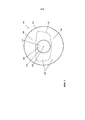
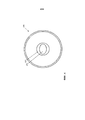
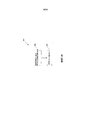
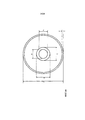
Фиг. 1 иллюстрирует вид спереди примера осуществления заготовки для линзы.FIG. 1 illustrates a front view of an embodiment of a lens blank.
Фиг. 2 иллюстрирует вид спереди примера осуществления линзы для очков.FIG. 2 illustrates a front view of an embodiment of a lens for glasses.
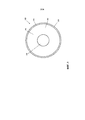
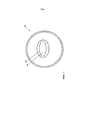
Фиг. 3 иллюстрирует вид спереди примера осуществления заготовки для линзы.FIG. 3 illustrates a front view of an embodiment of a lens preform.
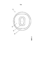
Фиг. 4 иллюстрирует вид спереди примера осуществления заготовки для линзы.FIG. 4 illustrates a front view of an embodiment of a lens preform.
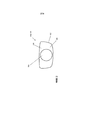
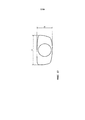
Фиг. 5 иллюстрирует вид в поперечном сечении примера осуществления части заготовки для линзы.FIG. 5 illustrates a cross-sectional view of an embodiment of a portion of a lens blank.
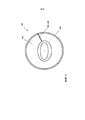
Фиг. 6 иллюстрирует вид спереди примера осуществления заготовки для линзы.FIG. 6 illustrates a front view of an embodiment of a lens blank.
Фиг. 7 иллюстрирует вид спереди примера осуществления заготовки для линзы.FIG. 7 illustrates a front view of an embodiment of a lens blank.
Фиг. 8 иллюстрирует вид спереди примера осуществления заготовки для линзы.FIG. 8 illustrates a front view of an embodiment of a lens blank.
Фиг. 9 иллюстрирует вид спереди примера осуществления заготовки для линзы.FIG. 9 illustrates a front view of an embodiment of a lens blank.
Фиг. 10 показывает технологичную схему примера осуществления способа изготовления жидкой линзы в сборе.FIG. 10 shows a flow chart of an embodiment of a method for manufacturing an assembled liquid lens.
Фиг. 11 показывает технологичную схему примера осуществления способа изготовления жидкой линзы в сборе.FIG. 11 shows a flow chart of an embodiment of a method for manufacturing an assembled liquid lens.
Фиг. 12 показывает технологичную схему примера осуществления способа изготовления жидкой линзы в сборке.FIG. 12 shows a flow chart of an embodiment of a method for manufacturing a liquid lens in an assembly.
Фиг. 13 иллюстрирует вид спереди линзы для очков по Фиг. 2 с добавленными надписями размеров.FIG. 13 illustrates a front view of the eyeglass lens of FIG. 2 with added size inscriptions.
Фиг. 14 иллюстрирует вид спереди заготовки для линзы по Фиг. 4 с добавленными надписями размеров.FIG. 14 illustrates a front view of the lens blank of FIG. 4 with added size inscriptions.
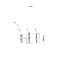
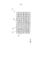
Фиг. 15 иллюстрирует вид спереди примера осуществления матрицы заготовок для линзы.FIG. 15 illustrates a front view of an embodiment of a matrix of lens blanks.
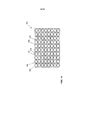
Фиг. 16 иллюстрирует вид спереди примера осуществления матрицы жидких линз.FIG. 16 illustrates a front view of an embodiment of a liquid lens array.
Данное изобретение будет описано со ссылкой на прилагаемые чертежи.The invention will be described with reference to the accompanying drawings.
ПОДРОБНОЕ ОПИСАНИЕDETAILED DESCRIPTION
Хотя обсуждаются определенные конфигурации и компоновки, следует понимать, что это сделано только в иллюстративных целях. Специалисту в данной области техники будет понятно, что могут использоваться и другие конфигурации и компоновки без отступления от сущности и объема данного изобретения. Специалисту в данной области техники будет очевидно, что данное изобретение может также быть использовано в различных других областях применения.Although certain configurations and arrangements are discussed, it should be understood that this is done for illustrative purposes only. One skilled in the art will understand that other configurations and arrangements may be used without departing from the spirit and scope of the present invention. It will be apparent to those skilled in the art that the invention may also be used in various other applications.
Следует отметить, что ссылки в описании на «одно осуществление», «осуществление», «пример осуществления» и прочее показывают, что описанный пример осуществления может содержать специфическую особенность, структуру или характеристику, но каждый пример осуществления необязательно содержит специфическую особенность, структуру или характеристику. Более того, такие фразы могут и не ссылаться на тот же самый пример осуществления. Кроме того, когда описываются специфическая особенность, структура или характеристика во взаимосвязи с некоторым примером осуществления, специалист в данной области техники будет иметь представление о влиянии такой особенности, структуры или характеристики во взаимосвязи с другими примерами осуществления, описываемыми или не описываемыми в явном виде.It should be noted that the references in the description to “one implementation”, “implementation”, “example of implementation” and so on show that the described embodiment may contain a specific feature, structure or characteristic, but each embodiment does not necessarily contain a specific feature, structure or characteristic . Moreover, such phrases may not refer to the same embodiment. In addition, when a specific feature, structure, or characteristic is described in conjunction with some embodiment, one skilled in the art will be aware of the effect of such a feature, structure, or characteristic in relation to other embodiments described or not described explicitly.
Фиг. 1 показывает вид спереди заготовки линзы 100. Заготовка линзы 100 включает жесткую линзу 102 и полугибкую надувную мембрану 104, прикрепленную к жесткой линзе 102. Заготовка линзы 100 может быть использована как жидкая линза, когда поставляется с промежуточной жидкостью. Например, термин «жидкая линза» может описывать оптическую линзу, образованную слоем жидкости и поверхностями, содержащими жидкость, например жесткая линза 102 и мембрана 104. В некоторых примерах осуществления такие жидкие линзы могут зависеть от гидростатического давления жидкости, чтобы вызвать изменение кривизны мембраны 104, которая может таким образом изменять оптическую силу жидкой линзы.FIG. 1 shows a front view of the lens blank 100. The lens blank 100 includes a
Жесткая линза 102 может быть изготовлена из стекла, пластика или другого подходящего материала. Другие подходящие материалы включают, например, без ограничения диэтиленгликоль бисалилкарбонат) (DEG-BAC), поли(метил метакрилат) (РММА), и патентованный полиаддукт мочевины, торговая марка TRIVEX (PPG). Линзы могут быть изготовлены из ударопрочного полимера и могут иметь покрытие от царапин или антибликовое покрытие.The
В некоторых примерах осуществления жесткая линза 102 может быть в форме одиночной линзы, содержащей базовую кривую и неподвижную оптическую силу. Жесткая линза 102 может иметь, по желанию, положительную, отрицательную или нулевую фиксированную оптическую силу. В некоторых примерах осуществления фиксированная оптическая сила жесткой линзы 102 находится в диапазоне, приблизительно от -1D до +1D. В некоторых примерах осуществления кривизна передней поверхности жесткой линзы 102 может быть такой же, как и кривизна задней поверхности жесткой линзы 102, что может привести, по существу, к нулевой оптической силе. В некоторых примерах осуществления жесткая линза 102 может быть выпуклой, вогнутой, сферической и/или асферической по своей форме. В некоторых примерах осуществления жесткая линза 102 может включать в себя компенсацию ее передней или задней поверхности, чтобы обеспечить желаемую оптическую силу на заданном уровне вздутия. Компенсация жесткой линзы 102 может, например, быть спроектирована на основе таких факторов, как геометрия мембраны 104, желаемый уровень вздутия или любой их комбинации или других подходящих факторов. Жесткая линза 102 может иметь диаметр в диапазоне приблизительно от 55 мм до 95 мм. В некоторых примерах осуществления диаметр жесткой линзы 102 может находиться в диапазоне приблизительно от 60 мм до 90 мм.In some embodiments, the
Мембрана 104 может быть изготовлена из полугибкого, прозрачного, водонепроницаемого материала, такого как, например, без ограничения четкие и упругие полиолефины, полигалоидные углеводороды, полициклоалифаты, простые полиэфиры, сложные полиэфиры, полиимиды и полиуретаны, например, пленки из поливинилидендифторида или дихлорида. Другие полимеры, пригодные для использования в качестве мембранных материалов, включают, например без ограничения, полисульфоны, полиуретаны, политиоуретаны, полиэтилентерефталаты, полимеры циклоолефинов и алифатические или алициклические полиэфиры. Мембрана 104 может быть изготовлена из биосовместимого непроницаемого материала, такого как циклоалифатический углеводород. В некоторых примерах осуществления толщина мембраны 104 может находиться в диапазоне, приблизительно от 10 микрон до 2 мм. Жидкость, используемая в жидких линзах, может быть бесцветной жидкостью, например, воздух или дистиллированная вода. В некоторых примерах осуществления жидкость окрашена, в зависимости от применения. Одним примером жидкости, которая могла бы быть использована, является жидкость, производимая компанией Dow Corning из Мидленда, Мичиган, под названием «масло для диффузионных насосов», которое обычно называют «кремниевым маслом». В некоторых примерах осуществления жидкость может быть алифатическим полисилоксаном, имеющим показатель преломления, соответствующий материалу линзы. В некоторых примерах осуществления жидкость может содержать по меньшей мере одну фотохромную добавку.
Заготовка линзы 100 разделена на зону полости 106 и присоединенную зону 108. В определенных примерах осуществления зона полости 106 проходит в радиальном направлении от центральной зоны 110 заготовки линзы 100. Центральная зона 110 показана на Фиг. 1, как находящаяся в самом центре заготовки линзы 100. В некоторых примерах осуществления центральная зона 110 может быть смещена от точного центра заготовки линзы 100 на желаемое расстояние. В полости зоны 106 полость образуется между мембраной 104 и жесткой линзой 102. Полость выполнена с возможностью быть частично заполненной жидкостью. Как только полость заполнена жидкостью, оптическая сила жидкой линзы определяется комбинацией топографии поверхности оптических поверхностей и их расстояний и индексов преломлений оптических компонентов жидкой линзы, представленной двумя поверхностями жесткой линзы, двумя поверхностями жидкости и двумя поверхностями мембраны. Как только объем жидкости изменяется в полости, мембрана 104 может раздуваться или сдуваться. Это раздувание служит для изменения оптической силы жидкой линзы. В некоторых примерах осуществления существует прямая и пропорциональная связь между изменением в силе жидкой линзы и уровнем достигаемого раздувания.The
В некоторых примерах осуществления присоединенная зона 108 вытянута в радиальном направлении от зоны полости 106. В некоторых примерах осуществления присоединенную зона 108 растянута к периферийному краю от жесткой линзы 102. В некоторых примерах осуществления присоединенная зона 108 не растянута к периферийному краю жесткой линзы 102. В некоторых примерах осуществления мембрана 104 выходит за рамки и выступы жесткой линзы 102. По всей присоединенной зоне 108 мембрана 104 присоединена и гибко герметично скреплена с жесткой линзой 102. В некоторых примерах осуществления мембрана 104 соединена напрямую с жесткой линзой 102. В некоторых примерах осуществления слой материала, такой как жесткий слой, зажат между мембраной 104 и жесткой линзой 102. В некоторых примерах осуществления это соединение создает герметичное скрепление мембраны 104 и жесткой линзы 102, что образует окружающий надежный диффузный барьер жидкости в полости. Мембрана 104 может быть соединена с жесткой линзой 102 различными способами. В некоторых примерах осуществления мембрана 104 соединена с жесткой линзой 102 с помощью теплового запечатывания. В некоторых примерах осуществления мембрана 104 соединена с жесткой линзой 102 с помощью лазерной сварки. В некоторых примерах осуществления мембрана 104 соединена с жесткой линзой 102 с помощью клея. Другие варианты соединения могут быть также использованы, не изменяя сущности и объема настоящего изобретения.In some embodiments, the
В некоторых примерах осуществления, где клей используется для соединения мембраны 104 с жесткой линзой 102, клей имеет индекс соответствия к мембране 104 жидкости, и жесткой линзе 102. Например, в некоторых примерах осуществления показатель индекса преломления твердой линзы, мембраны и жидкости, равен по крайней мере, трем значащим цифрам, таким ак 0,002 единицы на одну или более длину волн, например, при 550 нм. В некоторых примерах осуществления показатели индекса преломления каждого из различных компонентов находятся в диапазоне от приблизительно 1,47 до приблизительно 1,78, измеренные при 550 нм. В некоторых примерах осуществления показатели индекса преломления каждого из различных компонентов находятся в диапазоне от приблизительно 1,52 до приблизительно 1,70, измеренные при 550 нм. В некоторых примерах осуществления индекс преломления клея и индекс преломления жесткой линзы 102 не отличаются больше, чем на 0,05 единиц. В некоторых примерах осуществления индекс преломления клея и индекс преломления мембраны 104 не отличаются больше, чем на 0,05 единиц. В некоторых примерах осуществления индекс преломления клея и индекс преломления жидкости не отличаются больше, чем на 0,05 единиц. В некоторых примерах осуществления индекс преломления мембраны 104, индекс преломления жидкости, индекс преломления жесткой линзы 102 и индекс преломления клея не отличаются больше, чем на 0,05 единиц.In some embodiments, where the adhesive is used to connect the
В некоторых примерах осуществления присоединенная зона 108 имеет форму петли по типу кругового или эллиптического кольца. В некоторых примерах осуществления присоединенная зона 108 может быть заявлена негеометрической формой петли. Присоединенная зона 108 сохраняет нужные размеры таким образом, чтобы иметь присоединенную петлевую область, по ширине и высоте соответствующую размерам любых обычных линз для очков. Один из примеров обычной формы линзы для очков показан пунктирной линией по контуру 114. Другие формы обычных линз для очков могут включать, например, окружности, эллипсы, прямоугольники с закруглениями или неправильные формы. В некоторых примерах осуществления, где присоединенная зона 108 в форме кольца, ширина кольца может быть в диапазоне от около 18 мм до 40 мм. В некоторых примерах осуществления ширина кольца может меняться по всей поверхности линзы. В некоторых примерах осуществления формы обычных очковых линз могут быть совмещены с присоединенной зоной 108, имеющей ширину в диапазоне от около 6 мм до 24 мм. В некоторых примерах осуществления формы обычных очковых линз могут быть совмещены с присоединенной зоной 108, имеющей ширину в диапазоне от около 6 мм до около 18 мм. В некоторых примерах осуществления диапазон размеров «А» (расстояние от носа до виска) обычных оправ может быть совместим с присоединенной зоной 108, имеющей ширину в диапазоне от около 26 мм до 48 мм. В некоторых примерах осуществления диапазон размеров «В» (вертикальное расстояние) обычных оправ может быть совместим с присоединенной зоной 108, имеющей ширину в диапазоне от около 18 мм до 30 мм. В некоторых примерах осуществления диапазон расстояния между зрачками, который может быть совместим, составляет от около 45 мм до 75 мм.In some embodiments, the attached
Внутренняя периферийная кромка 116 присоединенной зоны 108 может быть в форме круга. В некоторых других примерах осуществления внутренняя периферийная кромка 116 находится в форме овала, прямоугольника или неправильной фигуры. В некоторых примерах осуществления присоединенная зона 108 имеет такие размеры, чтобы образовать петлю, которая может быть обрезана, чтобы образовать меньшую связанную петлю, имеющую любую внешнюю петлю по ширине от около 25 мм до 48 мм и любую внешнюю петлю по высоте от около 18 мм до 30 мм.The inner
Фиг. 2 иллюстрирует вид спереди очковой линзы 118 в форме обрезанной линзы 120. Обрезанная линза 120 формируется посредством технологической операции, которая урезает заготовку линзы 100 под типичную форму и размер очков. Заготовка линзы 100 может быть подрезана любым подходящим способом обрезки и/или обработки, например, с использованием стеклореза, пилы, сверла, ножниц, ножа, лазера, плазмореза или водоструйного режущего инструмента. Поскольку обрезаемая линза 120 просто вырезается из заготовки линзы 100 внутри присоединенной зоны 108, обрезанная линза 120 приведет к обрезке жесткой линзы 122 и обрезке мембраны 124, прикрепленной к обрезанной жесткой линзе 122. Подобно заготовке линзы 100, обрезанная линза 120 поделена на зону полости 106 и обрезанную присоединенную зону 126. Зона полости 106 имеет тот же размер и форму, как и зона полости 106 на заготовке линзы 100. Обрезанная присоединенная зона 126 вытянута к периферийному краю обрезанной жесткой линзы 122. Подобно присоединенной зоне 108 на заготовке линзы 100 на всем протяжении обрезанной присоединенной зоны 126, обрезанная мембрана 124 присоединена и гибко герметично скреплена с обрезанной жесткой линзой 122. Эта конфигурация обеспечивает гибкое герметичное скрепление мембраны 124 и обрезанной жесткой линзы 122 таким образом, чтобы предотвратить вытекание жидкости из зоны полости 106.FIG. 2 illustrates a front view of a spectacle lens 118 in the form of a cropped lens 120. A cropped lens 120 is formed by a process that cuts the
В обрезанной линзе 120 оптическая сила жидкой линзы включает в себя переменную часть, соответствующую зоне полости 106, и фиксированную часть, соответствующую обрезанной присоединенной зоне 126. В некоторых примерах осуществления обрезанная мембрана 124 является прозрачной и не обеспечивает значительную оптическую силу. В некоторых примерах осуществления оптическая сила фиксированной части обеспечивается только обрезанной жесткой линзой 122. В некоторых примерах осуществления оптическая сила переменной части обеспечивается комбинацией обрезанной жесткой линзы 122 и полости. В некоторых примерах осуществления оптическая сила переменной части находится в интервале от примерно -1.0D в не раздутом состоянии до примерно +1.0D в раздутом состоянии. В некоторых примерах осуществления оптическая сила переменной части находится в интервале от примерно +0.25D в не раздутом состоянии до +4.0D в раздутом состоянии. В некоторых примерах осуществления оптическая сила переменной части находится в интервале от примерно -12.00D в не раздутом состоянии до примерно +12.0D в раздутом состоянии.In the cropped lens 120, the optical power of the liquid lens includes a variable part corresponding to the area of the
На Фиг. 13 показан вид спереди примерной обрезанной линзы с дополненными метками размеров «А» и «В». Размер «А» указывает ширину обрезанной линзы.In FIG. 13 is a front view of an exemplary cropped lens with augmented size labels “A” and “B”. Size “A” indicates the width of the cropped lens.
Подходящие значения для этого измерения включают, но не ограничиваются значениями в диапазоне от приблизительно 30 мм до 60 мм. Размер «В» указывает высоту обрезанной линзы. Подходящие значения для этого измерения включают, но не ограничиваются значениями в диапазоне от приблизительно 20 мм до 40 мм.Suitable values for this measurement include, but are not limited to values in the range of about 30 mm to 60 mm. Size "B" indicates the height of the cropped lens. Suitable values for this measurement include, but are not limited to values in the range of about 20 mm to 40 mm.
Фиг. 3 иллюстрирует вид спереди заготовки линзы 128 в соответствии с примером осуществления. В этом примере осуществления мембрана 136 не вытянута к периферийной кромке жесткой линзы 138. Это может происходить потому, что мембрана не может иметь точно такой же размер или форму жесткой линзы или не может быть идеально выровнена с жесткой линзой во время процесса изготовления заготовки линзы. В некоторых примерах осуществления желательна мембрана различного размера, формы и/или желательно выравнивание по сравнению с жесткой линзой. Эта конфигурация делит заготовку линзы 128 на три зоны: первую зону полости 130, вторую присоединенную зону 132 и третью внешнюю зону 134. В некоторых примерах осуществления зона полости 130 и присоединенная зона 132 похожи на их соответствующие зоны на Фиг. 1. Внешняя зона 134 вытянута наружу в радиальном направлении от периферийной кромки мембраны 136 к периферийной кромке жесткой линзы 138. В некоторых примерах осуществления внешняя зона включает только жесткую линзу 138. В некоторых примерах осуществления внешняя зона 134 имеет ширину вдоль поверхности жесткой линзы 138 приблизительно от 2 мм до 10 мм. В некоторых примерах осуществления внешняя зона 134 имеет ширину вдоль поверхности жесткой линзы 138 от примерно 3 мм до 6 мм.FIG. 3 illustrates a front view of a
На Фиг. 4 показан вид спереди заготовки линзы 140 в соответствии с примером осуществления. Подобно заготовке линзы 100 на Фиг. 1 заготовка линзы 140 разделена на зону полости и присоединенную зону. Зона полости 142 заготовки линзы 140 разделена на асферическую подзону 144, вытянутую в радиальном направлении наружу от центральной области 146 зоны полости 142, и сферическую подзону 148, вытянутую радиально наружу от асферической подзоны 144 к присоединенной зоне 150. Кривизна жесткой линзы 152 внутри асферической подзоны 144 является асферической, а кривизна жесткой линзы 152 внутри сферической подзоны 148 имеет сферическую форму. Асферическая подзона 144 имеет форму круга. В других примерах осуществления асферическая подзона 144 имеет форму овала, прямоугольника или негеометрическую форму. В некоторых примерах осуществления сферическая подзона 148 может выступать в качестве зоны смешения, которая использует раздувание мембраны 154, чтобы обеспечить непрерывное сочетание кривизны от края асферической подзоны 144 до присоединенной зоны 150.In FIG. 4 is a front view of a
В некоторых примерах осуществления толщина мембраны 154 внутри асферической подзоны 144 может иметь контуры, чтобы компенсировать асферичность жесткой линзы 152 внутри асферической подзоны 144. В некоторых примерах осуществления термин "контур" может обозначать изменения в механическом измерении, такие как толщина, механические свойства, такие как провисание или оптическое свойство, такое как астигматизм или сила в x, y плоскости. В некоторых примерах осуществления контурная толщина может модулировать степень раздувания на общей площади поверхности, чтобы привести внутреннюю периферийную кромку 156 к фиксированной периферии жидкой линзы, которая может быть определена желаемой геометрической рамкой. В некоторых примерах осуществления контур компенсирует асферичность жесткой линзы 152, когда мембрана 154 одновременно раздута и не раздута. В некоторых примерах осуществления контур компенсирует асферичность жесткой линзы 152 только тогда, когда мембрана 154 раздута или не раздута.In some embodiments, the thickness of the
В некоторых примерах осуществления площадь асферической подзоны 144 может находиться в диапазоне от приблизительно 100 мм2 до 600 мм2. В некоторых примерах осуществления площадь асферической подзоны 144 может находиться в диапазоне от приблизительно 180 мм2 до 450 мм2. В некоторых примерах осуществления асферическая подзона 144 имеет форму непрерывного выпуклого полинома, такого как эллипс или круг. В некоторых примерах осуществления асферическая подзона 144 может быть в виде требуемой неправильной формы. В некоторых примерах осуществления, где асферическая подзона 144 имеет форму эллипса, эллипс может иметь эксцентриситет в диапазоне от примерно 0,95 до 0,50. В некоторых примерах осуществления эллипс может иметь эксцентриситет в диапазоне от примерно 0,95 до 0,65.In some embodiments, the area of the
В некоторых примерах осуществления вертикальный размер асферической подзоны 144 определяется на основе потенциального вертикального перемещения зрачка. Например, вертикальный размер асферической подзоны может быть определен на основе точки отношения человеческого глаза вдоль главной меридианы глаза, следующий за траекторией зрачка, когда взгляд осуществляется прямо вперед. В некоторых примерах осуществления этот вертикальный размер может быть примерно 25 мм. В некоторых примерах осуществления данный вертикальный размер может быть в интервале от примерно 18 мм до 24 мм.In some embodiments, the vertical size of the
В некоторых примерах осуществления сферическая подзона 148 имеет форму непрерывного выпуклого полинома, такого как эллипс или круг. В некоторых примерах осуществления сферическая подзона 148 может быть в виде требуемой неправильной формы. В некоторых примерах осуществления, где сферическая подзона 148 имеет форму круга, окружность может иметь радиус в пределах от около 10 мм до 30 мм. В некоторых примерах осуществления круг может иметь радиус в пределах от около 12 мм до 24 мм.In some embodiments, the
На Фиг. 14 показан вид спереди примерной заготовки линзы с добавленными надписями размеров от «С» до «Н».In FIG. 14 is a front view of an exemplary lens preform with added inscriptions of sizes from “C” to “H”.
Размер «С» указывает на диаметр заготовки линзы. Подходящие значения для этого измерения включают, но не ограничиваются значениями в диапазоне от приблизительно 60 мм до 95 мм.Size "C" indicates the diameter of the lens blank. Suitable values for this measurement include, but are not limited to values in the range of about 60 mm to 95 mm.
Размер «D» указывает высоту зоны полости. Подходящие значения для этого измерения включают, но не ограничиваются значениями в диапазоне от приблизительно 10 мм до 30 мм.Size "D" indicates the height of the cavity zone. Suitable values for this measurement include, but are not limited to values in the range of about 10 mm to 30 mm.
Размер «Е» указывает ширину зоны полости. Подходящие значения для этого измерения включают, но не ограничиваются значениями в диапазоне от приблизительно 20 мм до 40 мм.Size "E" indicates the width of the cavity zone. Suitable values for this measurement include, but are not limited to values in the range of about 20 mm to 40 mm.
Размер «F» указывает ширину между мембраной и краем заготовки линзы. Подходящие значения для этого измерения включают, но не ограничиваются, значениями в диапазоне от приблизительно 1 мм до 30 мм.Size “F” indicates the width between the membrane and the edge of the lens blank. Suitable values for this measurement include, but are not limited to, values in the range of about 1 mm to 30 mm.
Размер «G» указывает высоту асферической подзоны. Подходящие значения для этого измерения включают, но не ограничиваются значениями в диапазоне от приблизительно 10 мм до 20 мм.Size "G" indicates the height of the aspherical subzone. Suitable values for this measurement include, but are not limited to values in the range of about 10 mm to 20 mm.
Размер «Н» указывает ширину асферической подзоны. Подходящие значения для этого измерения включают, но не ограничиваются значениями в диапазоне от приблизительно 12 мм до 30 мм.Size "H" indicates the width of the aspherical subzone. Suitable values for this measurement include, but are not limited to values in the range of about 12 mm to 30 mm.
На Фиг. 5 показан вид в поперечном сечении жидкой линзы 158, в соответствии с примером осуществления. Как описано в патентной заявке США №13/407,416, которая полностью включена здесь в качестве ссылки, мембрана 160 может быть прикреплена к жесткой линзе 162 и включать в себя толстую зону 164, петельная часть 166 и центральную область диска 168. В некоторых примерах осуществления центральная область диска 168 может быть выполнена с возможностью обеспечения постоянной сферической мощности, большей, чем примерно 2,0 диоптрия, охватывая полное поле зрения пользователя вдоль горизонтальной оси. Например, полное поле зрения пользователя может составлять приблизительно 50 мм вдоль горизонтальной оси с центром в оптическом центре жидкой линзы 158.In FIG. 5 is a cross-sectional view of a
В некоторых примерах осуществления петельная часть 166 может вмещать неплоскую геометрию раздутой мембраны 160, оставаясь прикрепленной к жесткой линзе 162. В некоторых примерах осуществления петельная часть 166 может способствовать полному раздуванию мембраны 160, соответствующей диапазону мощности, минимизируя напряжения, переданные толстой зоне 164, которые могут вызвать астигматизм конструкции. В некоторых примерах осуществления петельная часть 166 может позволить обвисающие изменения, чтобы быть «поглощенными» без вызывания значительного оптического искажения в центральной области диска 168 и толстой зоне 164 мембраны 160. В некоторых примерах осуществления использование петельной части, таких как петельная часть 166, позволяет эффективно изолировать оптические свойства мембраны 160 в отдельных разделах. Петля, имеющая высокий коэффициент отношений, который может быть определен как отношение ширины к толщине, может быть особенно эффективной.In some embodiments, the
В некоторых примерах осуществления толстая зона 164 имеет толщину приблизительно 1 мм, а центральная область диска 168 имеет толщину приблизительно 0,225 мм. В некоторых примерах осуществления центральная область диска 168 имеет диаметр приблизительно 12 мм, а кромка диска имеет диаметр приблизительно 23,2 мм. Петельная часть 166 может быть образована между толстой зоной 164 и центральной областью диска 168. В некоторых примерах осуществления жидкая линза 158 может иметь угол обзора приблизительно 22 градусов между центром центральной области диска 168 и кромкой диска.In some embodiments, the
В некоторых примерах осуществления жидкая линза 158 может быть сконфигурирована для использования с рамкой в форме прямоугольника с закругленными углами, приблизительно размером 55 мм на 25 мм. Эта конфигурация может обеспечить приемлемую оптическую характеристику в центральной области диска 168 при сохранении приемлемых свойств относительно края рамки.In some embodiments, the
Термин «центральная оптическая зона» может быть использован для обозначения зоны обзора в жидкой линзе с центром на оптической оси, соответствующей местоположению глаза пользователя. В некоторых примерах осуществления оптическая ось совмещена с центром зрачка среднего или индивидуального пользователя. В некоторых примерах осуществления оптическая зона имеет ширину примерно 15 мм (по оси x) и высоту примерно 12 мм (по оси у), которые могут соответствовать горизонтальному углу обзора приблизительно +/-15 градусов и вертикальному углу обзора приблизительно +/-12 градусов.The term “central optical zone” can be used to designate a viewing area in a liquid lens centered on the optical axis corresponding to the location of the user's eye. In some embodiments, the optical axis is aligned with the center of the pupil of the average or individual user. In some embodiments, the optical zone has a width of about 15 mm (along the x axis) and a height of about 12 mm (along the y axis), which can correspond to a horizontal viewing angle of approximately +/- 15 degrees and a vertical viewing angle of approximately +/- 12 degrees.
В некоторых примерах осуществления центральная область диска 168 в мембране 160 имеет степень эксцентричности, равную приблизительно 0,9. То есть по горизонтали ширина примерно в 1,11 раза больше, чем по вертикали. Эта конструкция давит на положение переходной зоны, соответствующей петельной части для увеличения угла обзора в горизонтальном направлении, где она имеет меньшее напряжение относительно видимой ширины и горизонтальных движений глаза. В некоторых примерах осуществления вертикальная толщина поперечного сечения составляет примерно 0,200 мм, ширина примерно 3,7 мм, и соотношение сторон примерно 1:18,5. В некоторых примерах осуществления толщина горизонтального поперечного сечения составляет примерно 0,2 мм, с соответствующей шириной приблизительно 1,45 мм, и имеет соотношение сторон примерно 1:7.In some embodiments, the central region of the
Ширину петли, среди других конструктивных параметров, можно регулировать по желанию. Например, в некоторых примерах осуществления сочетание более широкой петли вдоль оси Y и более тонкой петли вдоль горизонтальной оси может служить для уменьшения астигматизма, вызванного раздуванием. В некоторых примерах осуществления ширина может быть в диапазоне от около 0,1 мм до 2,5 мм. В некоторых примерах осуществления толщина петельной части 166 может быть в диапазоне от приблизительно 0,01 мм до 0,25 мм.The width of the loop, among other design parameters, can be adjusted as desired. For example, in some embodiments, the combination of a wider loop along the Y axis and a thinner loop along the horizontal axis can serve to reduce astigmatism caused by inflation. In some embodiments, the width may be in the range of about 0.1 mm to 2.5 mm. In some embodiments, the thickness of the
В некоторых примерах осуществления толщина петельной части составляет от около 0,07 мм до около 0,20 мм. Для углов обзора, которые могут быть использованы для ближнего зрения (например, от около 0 до около 15 градусов), эта конфигурация может обеспечить качество изображения цели (например, имеющей круглое пятно на сетчатке приблизительно 10 микрон, что соответствует примерно 0.5D астигматизма, или примерно 0.25D сферического эквивалента замутненного изображения).In some embodiments, the thickness of the hinge portion is from about 0.07 mm to about 0.20 mm. For viewing angles that can be used for near vision (for example, from about 0 to about 15 degrees), this configuration can provide image quality of the target (for example, having a circular spot on the retina of approximately 10 microns, which corresponds to approximately 0.5D astigmatism, or approximately 0.25D of the spherical equivalent of the blurred image).
Некоторые примеры осуществления, описанные здесь, показывают относительно стабильный уровень сферической силы и астигматизма вдоль горизонтальной оси, с относительно коротким диапазоном сферической силы и астигматизма вдоль вертикальной оси. В качестве одного примера, линза может быть выполнена таким образом, что сферическая сила изменится меньше, чем приблизительно 0,25 диоптрий на протяжении примерно 10 мм (+/- приблизительно 5 мм) от оптического центра. В некоторых примерах осуществления линза выполнена таким образом, что сферическая сила изменяется меньше, чем около 0,25 диоптрий на протяжении примерно 20 мм (+/- примерно 10 мм) от оптического центра. В некоторых примерах осуществления сферическая сила и/или астигматизм вдоль вертикальной оси могут иметь равный или больший диапазон по сравнению с горизонтальной осью. Одним из показателей оптических характеристик может быть величина индуцированного астигматизма вдоль горизонтальной оси. В некоторых примерах осуществления вызванный астигматизм может быть меньше, чем приблизительно 0,5 диоптрий, по меньшей мере, на протяжении приблизительно 10 мм вдоль горизонтальной оси (+/- приблизительно 5 мм) от оптического центра, а в некоторых примерах осуществления на протяжении примерно 20 мм (+/- примерно 10 мм) от оптического центра.Some embodiments described herein show a relatively stable level of spherical force and astigmatism along the horizontal axis, with a relatively short range of spherical force and astigmatism along the vertical axis. As one example, a lens may be configured such that the spherical force changes less than about 0.25 diopters over about 10 mm (+/- about 5 mm) from the optical center. In some embodiments, the lens is configured such that the spherical force changes less than about 0.25 diopters over about 20 mm (+/- about 10 mm) from the optical center. In some embodiments, spherical force and / or astigmatism along the vertical axis may have an equal or greater range than the horizontal axis. One indicator of optical performance may be the magnitude of the induced astigmatism along the horizontal axis. In some embodiments, the induced astigmatism may be less than about 0.5 diopters, at least about 10 mm along the horizontal axis (+/- about 5 mm) from the optical center, and in some embodiments, about 20 mm (+/- approximately 10 mm) from the optical center.
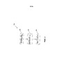
Фигуры 6-8 иллюстрируют альтернативные примеры осуществления заготовок линз. На Фиг. 6 показан вид спереди заготовки линзы 170 в соответствии с примером осуществления, где асферическая подзона 172 имеет форму овала и сферическая подзона 174 имеет форму круга. Фиг. 7 показывает вид спереди заготовки линзы 176 в соответствии с примером осуществления, в котором и асферическая подзона 178, и сферическая подзона 180 имеют форму овала. Фиг. 8 иллюстрирует вид спереди заготовки линзы 182 в соответствии с примером осуществления, в котором и внутренний периферийный край 184, и внешний периферийный край 186 присоединенной зоны 188 являются прямоугольниками с закруглениями.Figures 6-8 illustrate alternative embodiments of lens blanks. In FIG. 6 is a front view of a
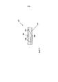
На Фиг. 9 показан вид спереди заготовки линзы 190 в соответствии с примером осуществления. Заготовка линзы 190 включает в себя канал 192, образованный внутри жесткой линзы 194. В некоторых примерах осуществления канал 192 может разрешить доступ к полости для обмена жидкости между полостью и резервуаром, содержащим избыток жидкости с целью нарушения гидростатического давления жидкости внутри полости. В некоторых примерах осуществления канал 192 сконфигурирован таким образом, чтобы жидкость могла войти или выйти из полости, чтобы раздуть или сдуть мембрану 198. В некоторых вариантах канал 192 соединен с резервуаром с помощью соединительной трубки. В некоторых примерах осуществления жидкая линза, канал, соединительная трубка и резервуар совместно образуют герметичный узел.In FIG. 9 is a front view of a
В некоторых примерах осуществления резервуар может быть сжат, чтобы выталкивать жидкость наружу в жидкую линзу с помощью соединительной трубки и/или канала. В некоторых примерах осуществления резервуар сжимается с помощью плунжера, сталкивающегося с диафрагмой, чтобы увеличить давление внутри резервуара. В некоторых примерах осуществления резервуар сжимается с помощью суппорта. Могут быть использованы другие подходящие конфигурации. Одна или более подходящие конфигурации описаны, например, в патенте США №8,087,778, выданном Gupta, который полностью включен здесь путем ссылки.In some embodiments, the reservoir may be compressed to push fluid outward into the fluid lens using a connecting tube and / or channel. In some embodiments, the reservoir is compressed using a plunger colliding with the diaphragm to increase the pressure inside the reservoir. In some embodiments, the reservoir is compressed using a caliper. Other suitable configurations may be used. One or more suitable configurations are described, for example, in US Pat. No. 8,087,778 to Gupta, which is incorporated herein by reference in its entirety.
Резервуар может быть включен в дужку, оправу очков или в любом желаемом месте. Резервуар может быть изготовлен из гибкого, прозрачного водонепроницаемого материала. Например, без ограничения, резервуар может быть изготовлен из поливинилового дифторида, такого, как термоусадочный VITON (R), поставляемый DuPont Performance Elastomers LLC of Wilmington, DE, DERAY-KYF 190, изготавливаемый DSG-CANUSA of Meckenheim, Germany (гибкий), RW-175 изготавливаемый Tyco Electronics Corp.of Berwyn, PA (бывшая Raychem Corp.) (полужесткий) или другого подходящего материала. Дополнительные варианты резервуаров описаны в публикации США №2011-0102735, которая полностью включена в настоящее описание путем ссылки.The tank can be included in the bow, frame of glasses or at any desired location. The tank may be made of a flexible, transparent, waterproof material. For example, without limitation, the reservoir may be made of polyvinyl difluoride, such as shrink VITON (R), supplied by DuPont Performance Elastomers LLC of Wilmington, DE, DERAY-
В качестве альтернативы или в дополнение, заготовка линзы 190 может включать в себя трубку 200, расположенную между мембраной 198 и жесткой линзой 194. Трубка 200 может быть не гибкой или гибкой, по желанию. В некоторых примерах осуществления трубка 200 выполнена из того же материала, что и резервуар. В некоторых примерах осуществления трубка 200 выполнена из одного или нескольких материалов, таких как TYGON (поливинилхлорид), PVDF (поливинилденфторид), и натуральный каучук. Например, PVDF может быть соответственно основан на его прочности, проницаемости и устойчивости к волнистости. Трубка 200 может быть прозрачной, полупрозрачной или непрозрачной. В некоторых примерах осуществления трубка 200 имеет по существу такой же показатель преломления, как один или несколько в жесткой линзе 194, мембране 198, и жидкости. Как и канал 192, трубка 200 может быть настроена так, чтобы позволять жидкости входить или выходить из полости для раздувания или сдувания мембраны 198. В примере осуществления трубка 200 вставлена в канал 192.Alternatively, or in addition, the
На Фиг. 10 представлена блок-схема 202 способа изготовления жидкой линзы в сборе в соответствии с примером осуществления. Ссылка приводится для частей жидкой линзы, как показано на Фиг. 1 и 2 только в качестве примера. То есть этот способ может быть использован для изготовления любой подходящий жидкой линзы, описанной здесь или в другом месте.In FIG. 10 is a
На этапе 204 часть мембраны 104 соединена с жесткой линзой 102 таким образом, что присоединенная область мембраны 104 гибко герметично скреплена с жесткой линзой 102. Любой подходящий связывающий процесс может быть использован для соединения мембраны с жесткой линзой. Например, как описано здесь, в некоторых примерах осуществления, мембрана 104 соединена с жесткой линзой 102 с помощью теплового запечатывания. В некоторых примерах осуществления мембрана 104 соединена с жесткой линзой 102 с помощью лазерной сварки. В некоторых примерах осуществления мембрана 104 соединена с жесткой линзой 102 с помощью клея. Площадь соединения имеет такие размеры, что заготовка линзы 100 может быть обрезана, чтобы сформировать обрезанную линзу 120, имеющую присоединенную петельную зону с шириной и высотой, соответствующую по размеру любой очковой линзе.At
Этап 206 включает в себя обрезанную заготовку линзы 100, чтобы сформировать обрезанную линзу 120, имеющую присоединенную петельную зону с шириной и высотой, соответствующую заданному размеру очковой линзы. Как описано здесь, заготовка линзы 100 может быть обрезана до заданной формы и размера очков любым подходящим способом обрезки и/или обработки, например, с использованием стеклореза, пилы, сверла, ножниц, ножа, лазера, плазмореза или водоструйного режущего инструмента.Step 206 includes a cropped
На Фиг. 11 показана блок-схема 208 для способа изготовления жидкой линзы в сборе, в соответствии с примером осуществления. Ссылка дается для частей жидкой линзы, показанных на Фиг. 9, только для примера. То есть этот способ может быть применен для изготовления любой подходящий жидкой линзы, описанной здесь или в другом месте. Этап 210 включает формирование канала 192 внутри жесткой линзы 194. Канал 192 может быть образован любым подходящим способом обработки, например, с помощью стеклореза, пилы, сверла, ножниц, ножа, лазера, плазмореза или водоструйного режущего инструмента. Канал 192 сконфигурирован таким образом, чтобы позволить жидкости входить или выходить из полости, чтобы раздуть или сдуть мембрану 198. В некоторых примерах осуществления этапы 204 и 206 в блок-схеме 208 останутся, по существу, такими же, как описано в настоящем документе для блок-схемы 202 на Фиг. 10.In FIG. 11 shows a
Фиг. 12 показывает блок-схему 212 для способа изготовления жидкой линзы в сборе, в соответствии с примером осуществления. Ссылка дается для частей жидкой линзы, показанных на Фиг. 9 только для примера. То есть этот способ может быть применен для изготовления любой подходящий жидкой линзы, описанной в данном документе, или в другом. Этап 214 включает в себя размещение трубки 200 между мембраной 198 и жесткой линзой 194 до того, как мембрана 198 гибко герметично скреплена и соединена с жесткой линзой 194. Это может быть достигнуто, например, путем прокладки трубки 200 через жесткую линзу 194 до того, как мембрана 198 соединена с жесткой линзой 194. Трубка 200 сконфигурирована таким образом, чтобы позволить жидкости входить или выходить в полость и раздувать или сдувать мембрану. В некоторых примерах осуществления этапы 204 и 206 блок-схемы 212 будут оставаться, по существу, такими же, как описано в настоящем документе для блок-схемы 202 на Фиг. 10.FIG. 12 shows a
На Фиг. 15 показан вид спереди матрицы 216, включающей в себя множество заготовок линз 218 (которые также могут быть названы как «малоразмерные линзы») в соответствии с примером осуществления. Каждая из линзовых заготовок 218 может являться любой подходящей линзовой заготовкой, описанной здесь. В некоторых примерах осуществления заготовки линзы 218 модифицируются из одной или более заготовок линз, описанных здесь, чтобы достичь желаемой матричной формы или конфигурации. Матрица 216 включает в себя 8 рядов и 10 столбцов заготовок линз 218, расположенных в прямоугольной форме. В некоторых примерах осуществления матрица 216 включает в себя большее или меньшее количество строк и/или столбцов. В некоторых примерах осуществления матрица 216 является, по желанию, не прямоугольной формой. Матрица 216 может быть сформирована из одной плоской жесткой линзы 220, таких как, например, одна или более жестких линз, описанных здесь. В некоторых примерах осуществления матрица 216 включает в себя множество частей материалов жестких линз. В некоторых примерах осуществления жесткая линза 220 включает в себя одну или несколько изогнутых частей жесткого материала. В некоторых примерах осуществления одна или несколько из множества заготовок линз 218 обеспечивают различные оптические свойства из одной или нескольких других заготовок линз 218 в матрице 216. Например, одна или несколько из множества линзовых заготовок 218 могут включать в себя различные материалы, толщину, кривизну или другие свойства.In FIG. 15 is a front view of an
Матрица 216 включает в себя вертикальные каналы 222 и горизонтальные каналы 224, образованные в жесткой линзе 220. Каналы могут, например, быть подходящими по глубине и ширине, чтобы способствовать разделению матрицы 216 на отдельные заготовки линз 218, либо на меньшую матрицу из множества заготовок линз 218. Способ разделения может включать в себя обрезку и/или любой подходящий способ обработки, описанный в данном документе, такой, как, например, с помощью стеклореза, пилы, сверла, ножниц, ножа, лазера, плазмореза или водоструйного режущего инструмента. В некоторых примерах осуществления каналы диагональные или изогнутые. Каналы могут быть в виде одной или нескольких желаемых форм. Например, каналы могут быть в форме одного или более прямоугольника, треугольника, круга, эллипса или иметь негеометрическую форму. В некоторых примерах осуществления матрица 216 не включает в себя каналы. В некоторых примерах осуществления матрица 216 включает линии отреза на или ниже поверхности матрицы 216 для облегчения разделения матрицы 216 или для других желаемых целей.The
На Фиг. 16 показан вид спереди матрицы 226 жидких линз 228 в соответствии с примером осуществления. Жидкие линзы 228 или желаемое множество жидких линз 228 могут быть нарезаны на части и использованы, например, в глазных или микрожидкостных устройствах. Каждая жидкая линза 228 включает в себя зону полости 230 и присоединенную зону 232, похожую на другие подходящие жидкие линзы, описанные здесь. Зона полости 230 может быть в форме круга. В некоторых примерах осуществления одна или более из зон полости 230 могут быть в других подходящих формах, таких как, например, эллипс. В некоторых примерах осуществления зона полости 230 выполнена с рельефом поверхности (например, углубление) для каждой жидкой линзы 228. Жесткая пластина 236 может быть в составе или изготовлена аналогично любым подходящим жестким линзам, описанным здесь. В некоторых примерах осуществления жесткая пластина 236 изготовлена литьем под давлением или литьем без давления из жидкого форполимера с использованием соответствующих формообразующих инструментов или вставок. В некоторых примерах осуществления жесткая пластина 236 изготовлена из плоской панели.In FIG. 16 is a front view of a
Матрица 226 дополнительно включает в себя каналы 234, которые гидравлически соединяют одну или несколько жидких линз 228 с одной или несколькими дополнительными жидкими линзами 228. В примере осуществления, показанном на Фиг. 16, каналы 234 связывают каждую жидкую линзу 228 с двумя соседними жидкими линзами в горизонтальном направлении. В некоторых примерах осуществления один или несколько каналов могут иметь ширину в диапазоне от около 20 мкм до около 1 мм. Каналы могут быть сконфигурированы для соединения смежных или несмежных жидких линз в одном или нескольких горизонтальных, вертикальных, диагональных или других направлениях, как требуется. Каналы 234 могут быть образованы, например, с помощью лазерной разметки. В некоторых примерах осуществления каналы 234 образованы путем водоструйной обработки.
В примере осуществления, показанном на Фиг. 16, несколько жидких линз 228 включают клапаны 238 внутри одного или более каналов 234. Клапаны 238 регулируются, чтобы гибко герметично скрепить один или несколько из каналов 234 и предотвратить вход или выход жидкости в определенную жидкую линзу 228. В некоторых примерах осуществления каждая жидкая линза 228 включает в себя, по меньшей мере, один клапан 238. В некоторых примерах осуществления клапаны 238 сконфигурированы так, чтобы автоматически гибко герметично скрепить канал 234, как только достигнуто нужное положение внутри зоны полости 230 или канала 234. Например, клапаны 238 могут быть сконфигурированы таким образом, чтобы автоматически гибко герметично скрепить канал 234, как только достигнуты или поддерживаются в течение заданного периода времени желаемое давление жидкости, объем, температура или скорость потока в пределах зоны полости 230 или канала 234.In the embodiment shown in FIG. 16, several
В некоторых примерах осуществления клапаны 238 функционально подключены к регулятору расхода. Регуляторы расхода могут быть использованы для контроля потока жидкости для одной жидкой линзы 228 или между множеством смежных или несмежных жидких линз 228. Регуляторы расхода могут быть с электрическим приводом. Один или несколько регуляторов расхода могут быть адресуемы, с помощью одного или нескольких логических контроллеров, для контроля потока жидкости внутри каждой жидкой линзы 228 по отдельности. В некоторых примерах осуществления контроль потоков жидкости в одной или нескольких жидких линзах 228 может регулировать оптическую силу для одной или нескольких жидких линз 228. В некоторых примерах осуществления такая конфигурация создает несколько оптических сил внутри матрицы линзы, образованной множеством малоразмерных линз 228. В некоторых примерах осуществления матрица линзы, образованной множеством малоразмерных линз 228, может быть в виде двухфокусных очков, имеющих две разные оптические силы.In some embodiments,
В некоторых примерах осуществления клапаны не используются для контроля оптической силы внутри множества жидких линз. Жидкие линзы 228 могут быть сконфигурированы для создания различных оптических сил в пределах матрицы 226 на основе различий между свойствами материала, или формами материалов, или компонентами. Например, матрица 226 может включать в себя жидкую линзу 228, имеющую различные мембранные материалы с различными характеристиками раздувания, различной кривизной линзы или разной толщиной канала, каждая из которых может повлиять на оптические силы одной или более жидких линз 228 в матрице 226.In some embodiments, valves are not used to control optical power within a plurality of liquid lenses.
Как показано на Фиг. 16, матрица 226 включает в себя восемь рядов и 10 столбцов жидких линз 228, расположенных в прямоугольной форме. В некоторых примерах осуществления матрица 226 включает в себя большее или меньшее количество рядов и/или столбцов. Например, матрица 226 может включать в себя несколько сотен, тысяч или более жидких линз 228, сформированных на одной пластине. В некоторых примерах осуществления матрица 226 включает в себя 900 жидких линз 228, с каждой жидкой линзой 228, имеющей площадь от примерно 1 мм до 10 мм.As shown in FIG. 16, the
Хотя выше были описаны различные примеры осуществления настоящего изобретения, следует понимать, что они были представлены только в качестве примера, а не ограничения. Специалистам в данной области техники будет очевидно, что различные изменения в форме и деталях могут быть сделаны без отступления от сущности и объема настоящего изобретения. Таким образом, широта и объем настоящего изобретения не должны быть ограничены ни одним из вышеописанных примеров осуществления, но должны быть определены только в соответствии со следующими требованиями формулы изобретения и их эквивалентами.Although various embodiments of the present invention have been described above, it should be understood that they were presented by way of example only and not limitation. Those skilled in the art will appreciate that various changes in form and detail can be made without departing from the spirit and scope of the present invention. Thus, the breadth and scope of the present invention should not be limited by any of the above embodiments, but should be determined only in accordance with the following claims and their equivalents.
Выбор материалов для каждой из частей в примерах осуществления в сборе, описанных в данном документе, продиктован требованиями механических свойств, температурной чувствительности, оптическими свойствами, такими как дисперсией, свойствами пластичности, или любого другого фактора очевидного специалисту в данной области техники. Например, фрагменты различной описанной сборки могут быть изготовлены с помощью любого подходящего способа, такого как отливка металлическим выдуванием (MIM), литьем, механической обработкой, пластмассовой отливкой под давлением и тому подобное. Детали в сборе могут иметь любую подходящую форму быть выполненными из пластмассы, металла или другого подходящего материала. В некоторых примерах осуществления может быть использован легкий материал, например, без ограничения, высокоударный прочный материал из пластмассы, алюминия, титана или тому подобное. В некоторых примерах осуществления одна или более из частей могут быть выполнены полностью или частично из прозрачного материала.The choice of materials for each of the parts in the assembled embodiments described herein is dictated by the requirements of mechanical properties, temperature sensitivity, optical properties such as dispersion, plasticity properties, or any other factor obvious to one skilled in the art. For example, fragments of the various assemblies described can be made using any suitable method, such as metal blow molding (MIM), injection molding, machining, plastic injection molding, and the like. The assembled parts may have any suitable shape, made of plastic, metal, or other suitable material. In some embodiments, a lightweight material may be used, for example, without limitation, a highly impact resistant material made of plastic, aluminum, titanium, or the like. In some embodiments, one or more of the parts may be made in whole or in part from a transparent material.
Далее, целью вышеизложенного реферата изобретения является предоставление Патентному ведомству США и общественности в общем, и, в частности, ученым, инженерам и специалистам - практикам в этой области техники, которые не знакомы с патентными или юридическими терминами или фразеологией, возможности быстро определить из беглого просмотра природу и сущность технического раскрытия заявки. Реферат изобретения не предназначен для какого-либо ограничения объема настоящего изобретения.Further, the purpose of the above summary of the invention is to provide the US Patent Office and the public in general, and, in particular, scientists, engineers and practitioners in this field of technology who are not familiar with patent or legal terms or phraseology, the ability to quickly determine from a quick look nature and nature of the technical disclosure of the application. The summary of the invention is not intended to limit the scope of the present invention in any way.
Claims (35)
Applications Claiming Priority (3)
| Application Number | Priority Date | Filing Date | Title |
|---|---|---|---|
| US13/549,078 | 2012-07-13 | ||
| US13/549,078 US9535264B2 (en) | 2012-07-13 | 2012-07-13 | Fluid lenses, lens blanks, and methods of manufacturing the same |
| PCT/US2013/050339 WO2014012036A1 (en) | 2012-07-13 | 2013-07-12 | Fluid lenses, lens blanks, and methods of manufacturing the same |
Publications (2)
| Publication Number | Publication Date |
|---|---|
| RU2015104896A RU2015104896A (en) | 2016-09-10 |
| RU2635404C2 true RU2635404C2 (en) | 2017-11-13 |
Family
ID=49913736
Family Applications (1)
| Application Number | Title | Priority Date | Filing Date |
|---|---|---|---|
| RU2015104896A RU2635404C2 (en) | 2012-07-13 | 2013-07-12 | Liquid lenses, linz preforms and methods of their manufacture |
Country Status (14)
| Country | Link |
|---|---|
| US (1) | US9535264B2 (en) |
| EP (1) | EP2872934A4 (en) |
| JP (1) | JP6441218B2 (en) |
| KR (1) | KR102073610B1 (en) |
| CN (1) | CN104620141B (en) |
| AU (1) | AU2013289924B2 (en) |
| BR (1) | BR112015000785A2 (en) |
| CA (1) | CA2879100A1 (en) |
| IL (1) | IL236709B (en) |
| MX (1) | MX343453B (en) |
| RU (1) | RU2635404C2 (en) |
| SG (1) | SG11201500253SA (en) |
| WO (1) | WO2014012036A1 (en) |
| ZA (1) | ZA201500329B (en) |
Families Citing this family (8)
| Publication number | Priority date | Publication date | Assignee | Title |
|---|---|---|---|---|
| WO2015107362A1 (en) * | 2014-01-17 | 2015-07-23 | The Centre For Vision In The Developing World Cic | Method of making a flexible membrane and mold therefor, membrane and variable focus lens |
| US9811095B2 (en) * | 2014-08-06 | 2017-11-07 | Lenovo (Singapore) Pte. Ltd. | Glasses with fluid-fillable membrane for adjusting focal length of one or more lenses of the glasses |
| US9874325B2 (en) * | 2015-04-10 | 2018-01-23 | Simply Leds, Llc | Configurable overhead light |
| CN114532976A (en) | 2016-05-31 | 2022-05-27 | 酷拉公司 | Implantable intraocular pressure sensor and method of use |
| US10928638B2 (en) | 2016-10-31 | 2021-02-23 | Dolby Laboratories Licensing Corporation | Eyewear devices with focus tunable lenses |
| CN107422493A (en) * | 2017-06-22 | 2017-12-01 | 华中科技大学 | A kind of liquid-filled Zoom glasses of manual focusing |
| WO2019164940A1 (en) * | 2018-02-20 | 2019-08-29 | Qura, Inc. | Coating for implantable devices |
| GB2582325A (en) * | 2019-03-19 | 2020-09-23 | Derek Snelgrove John | Universal spectacle lenses |
Citations (5)
| Publication number | Priority date | Publication date | Assignee | Title |
|---|---|---|---|---|
| US20040001180A1 (en) * | 2002-07-01 | 2004-01-01 | Saul Epstein | Variable focus lens with internal refractive surface |
| US20070263293A1 (en) * | 2000-10-20 | 2007-11-15 | Holochip Corporation | Fluidic lens with electrostatic actuation |
| US20090268303A1 (en) * | 2006-07-10 | 2009-10-29 | Sony Corporation | Lens array |
| US20110085243A1 (en) * | 2009-10-13 | 2011-04-14 | Amitava Gupta | Non-Round Fluid Filled Lens Optic |
| US20110085131A1 (en) * | 2009-10-14 | 2011-04-14 | Adlens Beacon, Inc. | Aspheric Fluid Filled Lens Optic |
Family Cites Families (99)
| Publication number | Priority date | Publication date | Assignee | Title |
|---|---|---|---|---|
| US2576581A (en) | 1946-07-09 | 1951-11-27 | Benjamin F Edwards | Polyfocal spectacles |
| US2836101A (en) | 1955-09-01 | 1958-05-27 | Swart Dev Company De | Optical elements |
| BE561219A (en) | 1956-10-08 | |||
| GB1171294A (en) | 1965-11-16 | 1969-11-19 | Agfa Gevaert Nv | Light-Transmitting Screens |
| GB1209234A (en) * | 1968-03-11 | 1970-10-21 | Nat Res Dev | Improvements in or relating to variable focus lenses |
| US3614215A (en) | 1970-04-23 | 1971-10-19 | Leo Mackta | Fluid bifocal spectacle |
| GB2105866B (en) * | 1981-07-29 | 1985-05-09 | Lynell Med Tech Inc | Intraocular and extraocular lens construction and making by selective erosion |
| US4450593A (en) | 1981-11-09 | 1984-05-29 | Lynell Medical Technology Inc. | Intraocular and contact lens construction |
| GB2183059B (en) | 1985-11-05 | 1989-09-27 | Michel Treisman | Suspension system for a flexible optical membrane |
| US4827485A (en) * | 1986-06-06 | 1989-05-02 | Lightwave Electronics Corp. | Diode pumped solid state laser |
| JPS6410211A (en) * | 1987-07-02 | 1989-01-13 | Yuichi Hasegawa | Method for working spectacle lens |
| IL83179A0 (en) | 1987-07-14 | 1987-12-31 | Daniel Barnea | Variable lens |
| US4969729A (en) * | 1988-08-19 | 1990-11-13 | 501 Opticast International Corporation | Composite plastic lens having a positioned optical axis and method of making the same |
| FR2651584B1 (en) | 1989-09-07 | 1992-11-13 | Essilor Int | EYEWEAR MOUNT BRANCH WITH INTERCHANGEABLE BRANCH BODY. |
| US5080839A (en) | 1990-04-17 | 1992-01-14 | Johnson & Johnson Vision Products, Inc. | Process for hydrating soft contact lenses |
| US5138494A (en) | 1990-05-07 | 1992-08-11 | Stephen Kurtin | Variable focal length lens |
| US5229885A (en) | 1991-09-03 | 1993-07-20 | Quaglia Lawrence D | Infinitely variable focal power lens units precisely matched to varying distances by radar and electronics |
| US5440357A (en) | 1991-09-03 | 1995-08-08 | Lawrence D. Quaglia | Vari-lens phoropter and automatic fast focusing infinitely variable focal power lens units precisely matched to varying distances by radar and electronics |
| US5182585A (en) | 1991-09-26 | 1993-01-26 | The Arizona Carbon Foil Company, Inc. | Eyeglasses with controllable refracting power |
| USD340733S (en) * | 1992-08-21 | 1993-10-26 | Hall Ronald B | Novelty spectacles |
| US5371629A (en) * | 1993-02-04 | 1994-12-06 | Kurtin; Stephen | Non-circular variable focus lens |
| US5739959A (en) | 1993-07-20 | 1998-04-14 | Lawrence D. Quaglia | Automatic fast focusing infinitely variable focal power lens units for eyeglasses and other optical instruments controlled by radar and electronics |
| JPH0749404A (en) | 1993-08-05 | 1995-02-21 | Nippondenso Co Ltd | Lens with variable focal point |
| US5668620A (en) | 1994-04-12 | 1997-09-16 | Kurtin; Stephen | Variable focal length lenses which have an arbitrarily shaped periphery |
| US5804107A (en) * | 1994-06-10 | 1998-09-08 | Johnson & Johnson Vision Products, Inc. | Consolidated contact lens molding |
| US5900921A (en) | 1994-07-06 | 1999-05-04 | Jong-Deok Park | Lens for diplopia and amblyopia and glasses using the same |
| US5515203A (en) | 1994-07-08 | 1996-05-07 | Nye; William S. | Educational lens |
| US5999328A (en) | 1994-11-08 | 1999-12-07 | Kurtin; Stephen | Liquid-filled variable focus lens with band actuator |
| US5774274A (en) | 1995-05-12 | 1998-06-30 | Schachar; Ronald A. | Variable focus lens by small changes of the equatorial lens diameter |
| GB9511091D0 (en) | 1995-06-01 | 1995-07-26 | Silver Joshua D | Variable power spectacles |
| US5684637A (en) * | 1995-07-19 | 1997-11-04 | Floyd; Johnnie E. | Fluid filled and pressurized lens with flexible optical boundary having variable focal length |
| CA2265723C (en) | 1996-09-13 | 2008-03-11 | Joshua David Silver | Improvements in or relating to variable focus lenses |
| US6104446A (en) * | 1996-12-18 | 2000-08-15 | Blankenbecler; Richard | Color separation optical plate for use with LCD panels |
| US6626532B1 (en) | 1997-06-10 | 2003-09-30 | Olympus Optical Co., Ltd. | Vari-focal spectacles |
| GB9805977D0 (en) | 1998-03-19 | 1998-05-20 | Silver Joshua D | Improvements in variable focus optical devices |
| US5973852A (en) | 1998-03-26 | 1999-10-26 | The United States Of America As Represented By The Secretary Of The Air Force | Variable power fluid lens |
| US6552860B1 (en) | 1998-05-01 | 2003-04-22 | Ray M. Alden | Variable Fresnel type structures and process |
| US5956183A (en) * | 1998-05-26 | 1999-09-21 | Epstein; Saul | Field-customizable variable focal length lens |
| US6040947A (en) | 1998-06-09 | 2000-03-21 | Lane Research | Variable spectacle lens |
| US6355124B1 (en) | 1999-05-24 | 2002-03-12 | Bmc Vision-Ease Lens, Inc. | Lamination apparatus and process |
| US6619799B1 (en) | 1999-07-02 | 2003-09-16 | E-Vision, Llc | Optical lens system with electro-active lens having alterably different focal lengths |
| US7604349B2 (en) | 1999-07-02 | 2009-10-20 | E-Vision, Llc | Static progressive surface region in optical communication with a dynamic optic |
| US6053610A (en) | 1999-07-15 | 2000-04-25 | Lane Research | Actuation mechanism for variable focal length spectacles |
| US6288846B1 (en) | 1999-09-24 | 2001-09-11 | Arizona Carbon Foil Co., Inc. | Variable focal-length lens assembly |
| US7646544B2 (en) | 2005-05-14 | 2010-01-12 | Batchko Robert G | Fluidic optical devices |
| GB0100031D0 (en) | 2001-01-02 | 2001-02-14 | Silver Joshua D | Variable focus optical apparatus |
| US7102602B2 (en) * | 2001-09-18 | 2006-09-05 | Alphamicron, Inc. | Doubly curved optical device for eyewear and method for making the same |
| US6715876B2 (en) | 2001-11-19 | 2004-04-06 | Johnnie E. Floyd | Lens arrangement with fluid cell and prescriptive element |
| EP1532489A2 (en) | 2002-08-23 | 2005-05-25 | Nikon Corporation | Projection optical system and method for photolithography and exposure apparatus and method using same |
| WO2004046768A2 (en) | 2002-11-20 | 2004-06-03 | Powervision | Lens system and method for power adjustment |
| CN101825762A (en) | 2003-10-23 | 2010-09-08 | 安德里斯·奥布雷斯基 | Imaging optical system |
| US6992843B2 (en) | 2003-12-16 | 2006-01-31 | Metastable Instruments, Inc. | Precision optical wedge light beam scanner |
| JP2005284066A (en) * | 2004-03-30 | 2005-10-13 | Nippon Tenganyaku Kenkyusho:Kk | Variable focus lens, and instrument and display using variable focus lens |
| US7453646B2 (en) * | 2004-03-31 | 2008-11-18 | The Regents Of The University Of California | Fluidic adaptive lens systems and methods |
| US8018658B2 (en) | 2004-03-31 | 2011-09-13 | The Regents Of The Univeristy Of California | Fluidic adaptive lens systems and methods |
| AU2005267561A1 (en) * | 2004-03-31 | 2006-02-02 | The Regents Of The University Of California | Fluidic adaptive lens |
| US7359124B1 (en) | 2004-04-30 | 2008-04-15 | Louisiana Tech University Research Foundation As A Division Of The Louisiana Tech University Foundation | Wide-angle variable focal length lens system |
| US20060011617A1 (en) * | 2004-07-13 | 2006-01-19 | Ricardo Covarrubias | Automated laser cutting of optical lenses |
| ATE534925T1 (en) | 2004-07-20 | 2011-12-15 | Agency Science Tech & Res | MICRO LENS WITH VARIABLE FOCAL LENGTH |
| GB2417650A (en) | 2004-07-30 | 2006-03-01 | Orange Personal Comm Serv Ltd | Tunnelling IPv6 packets over IPv4 packet radio network wherein an IPv6 address including a tunnel end identifier of the IPv4 bearer is formed |
| JP2006072266A (en) * | 2004-09-06 | 2006-03-16 | Olympus Corp | Optical characteristic variable optical element |
| US20060066808A1 (en) | 2004-09-27 | 2006-03-30 | Blum Ronald D | Ophthalmic lenses incorporating a diffractive element |
| US7826145B2 (en) | 2004-11-05 | 2010-11-02 | The Regents Of The University Of California | Fluidic adaptive lens systems with pumping systems |
| US7142369B2 (en) | 2005-01-21 | 2006-11-28 | Research Foundation Of The University Of Central Florida, Inc. | Variable focus liquid lens |
| US7325922B2 (en) | 2005-03-21 | 2008-02-05 | Quexta, Inc | Adjustable focus eyeglasses |
| US7338159B2 (en) | 2005-03-21 | 2008-03-04 | Brett Spivey | Adjustable focus lenses |
| US20060245071A1 (en) | 2005-04-29 | 2006-11-02 | Agilent Technologies | Lens correction element, system and method |
| US7697214B2 (en) | 2005-05-14 | 2010-04-13 | Holochip Corporation | Fluidic lens with manually-adjustable focus |
| US8064142B2 (en) * | 2005-05-14 | 2011-11-22 | Holochip Corporation | Fluidic lens with reduced optical aberration |
| JP2009524838A (en) * | 2005-10-28 | 2009-07-02 | ジェイ アンド ジェイ テクノロジーズ リミテッド | Variable focus lens |
| GB0613688D0 (en) * | 2006-07-10 | 2006-08-16 | Silver Joshua D | Variable focus lens and spectacles |
| GB0522030D0 (en) * | 2005-10-28 | 2005-12-07 | Silver Joshua D | Variable focus lens |
| EP1963893A2 (en) | 2005-12-12 | 2008-09-03 | Koninklijke Philips Electronics N.V. | Solution flow prevention in fluid focus lenses |
| US7382544B2 (en) | 2006-02-10 | 2008-06-03 | Honeywell International Inc. | Devices and related methods for light distribution |
| US7969549B2 (en) * | 2006-06-30 | 2011-06-28 | Asml Netherlands B.V. | Liquid filled lens element, lithographic apparatus comprising such an element and device manufacturing method |
| US7256943B1 (en) | 2006-08-24 | 2007-08-14 | Teledyne Licensing, Llc | Variable focus liquid-filled lens using polyphenyl ethers |
| US7866816B2 (en) * | 2006-10-10 | 2011-01-11 | Lane Research, Llc | Variable focus spectacles |
| US7324287B1 (en) | 2006-11-07 | 2008-01-29 | Corning Incorporated | Multi-fluid lenses and optical devices incorporating the same |
| KR20080043106A (en) | 2006-11-13 | 2008-05-16 | 삼성전자주식회사 | Optical lens and manufacturing method thereof |
| US20080117521A1 (en) | 2006-11-17 | 2008-05-22 | Lucent Technologies Inc. | Liquid lenses with cycloalkanes |
| US7864440B2 (en) * | 2006-11-24 | 2011-01-04 | Varioptic, S.A. | Optical lens with variable focal length |
| US7369321B1 (en) | 2007-01-16 | 2008-05-06 | University Of Central Florida Research Foundation, Inc. | Variable-focus liquid lens |
| US8922902B2 (en) * | 2010-03-24 | 2014-12-30 | Mitsui Chemicals, Inc. | Dynamic lens |
| EP2034338A1 (en) * | 2007-08-11 | 2009-03-11 | ETH Zurich | Liquid Lens System |
| US20090195882A1 (en) | 2008-02-05 | 2009-08-06 | Bolle Cristian A | Mechanical lenses |
| JP4544331B2 (en) | 2008-04-04 | 2010-09-15 | ソニー株式会社 | Conversion lens device and imaging device |
| GB0806561D0 (en) * | 2008-04-10 | 2008-05-14 | Adlens Ltd | Variable focus lens and spectacles |
| US20100033830A1 (en) | 2008-08-11 | 2010-02-11 | Man Fat Yung | Wearable image display device |
| US20100208194A1 (en) | 2009-02-13 | 2010-08-19 | Amitava Gupta | Variable focus liquid filled lens apparatus |
| US8087778B2 (en) | 2009-02-13 | 2012-01-03 | Adlens Beacon, Inc. | Variable focus liquid filled lens mechanism |
| US20100284089A1 (en) * | 2009-05-07 | 2010-11-11 | San-Woei Shyu | Stacked optical glass lens array, stacked lens module and manufacturing method thereof |
| FR2950162B1 (en) * | 2009-09-14 | 2011-10-07 | Essilor Int | METHOD FOR PRODUCING A DETOURING SETTING OF AN OPHTHALMIC LENS |
| US8817381B2 (en) | 2009-10-13 | 2014-08-26 | Adlens Beacon, Inc. | Full field membrane design for non-round liquid lens assemblies |
| US8596781B2 (en) | 2009-10-15 | 2013-12-03 | Adlens Beacon, Inc. | Fluid filled lens reservoir system and manufacturing method of the reservoir system |
| US8353593B2 (en) | 2009-10-15 | 2013-01-15 | Adlens Beacon, Inc. | Hinge mechanism for a fluid filled lens assembly |
| WO2011163668A2 (en) * | 2010-06-25 | 2011-12-29 | Pixeloptics, Inc. | High performance, low cost multifocal lens having dynamic progressive optical power region |
| US9036264B2 (en) | 2010-08-12 | 2015-05-19 | Adlens Beacon, Inc. | Fluid-filled lenses and their ophthalmic applications |
| MX2013004022A (en) | 2010-10-11 | 2013-07-05 | Adlens Beacon Inc | Non powered concepts for a wire frame of fluid filled lenses. |
| JP2012128106A (en) * | 2010-12-14 | 2012-07-05 | Citizen Holdings Co Ltd | Method for manufacturing liquid crystal fresnel lens and liquid crystal fresnel lens |
-
2012
- 2012-07-13 US US13/549,078 patent/US9535264B2/en not_active Expired - Fee Related
-
2013
- 2013-07-12 WO PCT/US2013/050339 patent/WO2014012036A1/en active Application Filing
- 2013-07-12 MX MX2015000553A patent/MX343453B/en active IP Right Grant
- 2013-07-12 BR BR112015000785A patent/BR112015000785A2/en not_active Application Discontinuation
- 2013-07-12 EP EP13816228.4A patent/EP2872934A4/en not_active Withdrawn
- 2013-07-12 AU AU2013289924A patent/AU2013289924B2/en not_active Ceased
- 2013-07-12 KR KR1020157002062A patent/KR102073610B1/en active IP Right Grant
- 2013-07-12 CA CA2879100A patent/CA2879100A1/en not_active Abandoned
- 2013-07-12 RU RU2015104896A patent/RU2635404C2/en not_active IP Right Cessation
- 2013-07-12 SG SG11201500253SA patent/SG11201500253SA/en unknown
- 2013-07-12 CN CN201380047635.0A patent/CN104620141B/en not_active Expired - Fee Related
- 2013-07-12 JP JP2015521857A patent/JP6441218B2/en not_active Expired - Fee Related
-
2015
- 2015-01-13 IL IL236709A patent/IL236709B/en active IP Right Grant
- 2015-01-16 ZA ZA2015/00329A patent/ZA201500329B/en unknown
Patent Citations (5)
| Publication number | Priority date | Publication date | Assignee | Title |
|---|---|---|---|---|
| US20070263293A1 (en) * | 2000-10-20 | 2007-11-15 | Holochip Corporation | Fluidic lens with electrostatic actuation |
| US20040001180A1 (en) * | 2002-07-01 | 2004-01-01 | Saul Epstein | Variable focus lens with internal refractive surface |
| US20090268303A1 (en) * | 2006-07-10 | 2009-10-29 | Sony Corporation | Lens array |
| US20110085243A1 (en) * | 2009-10-13 | 2011-04-14 | Amitava Gupta | Non-Round Fluid Filled Lens Optic |
| US20110085131A1 (en) * | 2009-10-14 | 2011-04-14 | Adlens Beacon, Inc. | Aspheric Fluid Filled Lens Optic |
Also Published As
| Publication number | Publication date |
|---|---|
| SG11201500253SA (en) | 2015-04-29 |
| CA2879100A1 (en) | 2014-01-16 |
| US9535264B2 (en) | 2017-01-03 |
| JP2015522184A (en) | 2015-08-03 |
| WO2014012036A1 (en) | 2014-01-16 |
| AU2013289924B2 (en) | 2016-12-22 |
| MX343453B (en) | 2016-11-07 |
| KR102073610B1 (en) | 2020-02-05 |
| AU2013289924A1 (en) | 2015-02-05 |
| CN104620141A (en) | 2015-05-13 |
| US20140016087A1 (en) | 2014-01-16 |
| RU2015104896A (en) | 2016-09-10 |
| IL236709A0 (en) | 2015-02-26 |
| EP2872934A4 (en) | 2016-03-09 |
| ZA201500329B (en) | 2016-11-30 |
| MX2015000553A (en) | 2015-09-07 |
| BR112015000785A2 (en) | 2017-06-27 |
| KR20150034739A (en) | 2015-04-03 |
| IL236709B (en) | 2019-06-30 |
| JP6441218B2 (en) | 2018-12-19 |
| EP2872934A1 (en) | 2015-05-20 |
| CN104620141B (en) | 2017-04-05 |
Similar Documents
| Publication | Publication Date | Title |
|---|---|---|
| RU2635404C2 (en) | Liquid lenses, linz preforms and methods of their manufacture | |
| JP6711895B2 (en) | Variable focus liquid filled lens instrument | |
| JP6348475B2 (en) | Aspheric fluid-filled lens optics | |
| EP2603823B1 (en) | Fluid-filled lenses and their ophthalmic applications | |
| JP2019174820A (en) | Variable focus liquid filled lens mechanism | |
| US4435050A (en) | Contact lens assembly with haptic and method for making the same | |
| US20120019773A1 (en) | High performance, low cost multifocal lens having dynamic progressive optical power region | |
| TW201219842A (en) | High performance, low cost multifocal lens having dynamic progressive optical power region | |
| WO2013101940A1 (en) | Photochromic fluid filled lenses and methods of manufacture thereof | |
| AU2015204373B2 (en) | Aspheric fluid filled lens optic |
Legal Events
| Date | Code | Title | Description |
|---|---|---|---|
| MM4A | The patent is invalid due to non-payment of fees |
Effective date: 20190713 |