RU2632248C2 - Management of lighting devices - Google Patents
Management of lighting devices Download PDFInfo
- Publication number
- RU2632248C2 RU2632248C2 RU2014150541A RU2014150541A RU2632248C2 RU 2632248 C2 RU2632248 C2 RU 2632248C2 RU 2014150541 A RU2014150541 A RU 2014150541A RU 2014150541 A RU2014150541 A RU 2014150541A RU 2632248 C2 RU2632248 C2 RU 2632248C2
- Authority
- RU
- Russia
- Prior art keywords
- probe signal
- active sensor
- sensor
- control system
- signal
- Prior art date
Links
Images

Classifications
-
- H—ELECTRICITY
- H05—ELECTRIC TECHNIQUES NOT OTHERWISE PROVIDED FOR
- H05B—ELECTRIC HEATING; ELECTRIC LIGHT SOURCES NOT OTHERWISE PROVIDED FOR; CIRCUIT ARRANGEMENTS FOR ELECTRIC LIGHT SOURCES, IN GENERAL
- H05B47/00—Circuit arrangements for operating light sources in general, i.e. where the type of light source is not relevant
- H05B47/10—Controlling the light source
- H05B47/105—Controlling the light source in response to determined parameters
- H05B47/115—Controlling the light source in response to determined parameters by determining the presence or movement of objects or living beings
-
- G—PHYSICS
- G01—MEASURING; TESTING
- G01S—RADIO DIRECTION-FINDING; RADIO NAVIGATION; DETERMINING DISTANCE OR VELOCITY BY USE OF RADIO WAVES; LOCATING OR PRESENCE-DETECTING BY USE OF THE REFLECTION OR RERADIATION OF RADIO WAVES; ANALOGOUS ARRANGEMENTS USING OTHER WAVES
- G01S15/00—Systems using the reflection or reradiation of acoustic waves, e.g. sonar systems
- G01S15/02—Systems using the reflection or reradiation of acoustic waves, e.g. sonar systems using reflection of acoustic waves
- G01S15/04—Systems determining presence of a target
-
- H—ELECTRICITY
- H05—ELECTRIC TECHNIQUES NOT OTHERWISE PROVIDED FOR
- H05B—ELECTRIC HEATING; ELECTRIC LIGHT SOURCES NOT OTHERWISE PROVIDED FOR; CIRCUIT ARRANGEMENTS FOR ELECTRIC LIGHT SOURCES, IN GENERAL
- H05B47/00—Circuit arrangements for operating light sources in general, i.e. where the type of light source is not relevant
- H05B47/10—Controlling the light source
- H05B47/105—Controlling the light source in response to determined parameters
-
- H—ELECTRICITY
- H05—ELECTRIC TECHNIQUES NOT OTHERWISE PROVIDED FOR
- H05B—ELECTRIC HEATING; ELECTRIC LIGHT SOURCES NOT OTHERWISE PROVIDED FOR; CIRCUIT ARRANGEMENTS FOR ELECTRIC LIGHT SOURCES, IN GENERAL
- H05B47/00—Circuit arrangements for operating light sources in general, i.e. where the type of light source is not relevant
- H05B47/10—Controlling the light source
- H05B47/175—Controlling the light source by remote control
- H05B47/19—Controlling the light source by remote control via wireless transmission
-
- G—PHYSICS
- G01—MEASURING; TESTING
- G01S—RADIO DIRECTION-FINDING; RADIO NAVIGATION; DETERMINING DISTANCE OR VELOCITY BY USE OF RADIO WAVES; LOCATING OR PRESENCE-DETECTING BY USE OF THE REFLECTION OR RERADIATION OF RADIO WAVES; ANALOGOUS ARRANGEMENTS USING OTHER WAVES
- G01S15/00—Systems using the reflection or reradiation of acoustic waves, e.g. sonar systems
- G01S15/02—Systems using the reflection or reradiation of acoustic waves, e.g. sonar systems using reflection of acoustic waves
- G01S15/50—Systems of measurement, based on relative movement of the target
- G01S15/52—Discriminating between fixed and moving objects or between objects moving at different speeds
-
- Y—GENERAL TAGGING OF NEW TECHNOLOGICAL DEVELOPMENTS; GENERAL TAGGING OF CROSS-SECTIONAL TECHNOLOGIES SPANNING OVER SEVERAL SECTIONS OF THE IPC; TECHNICAL SUBJECTS COVERED BY FORMER USPC CROSS-REFERENCE ART COLLECTIONS [XRACs] AND DIGESTS
- Y02—TECHNOLOGIES OR APPLICATIONS FOR MITIGATION OR ADAPTATION AGAINST CLIMATE CHANGE
- Y02B—CLIMATE CHANGE MITIGATION TECHNOLOGIES RELATED TO BUILDINGS, e.g. HOUSING, HOUSE APPLIANCES OR RELATED END-USER APPLICATIONS
- Y02B20/00—Energy efficient lighting technologies, e.g. halogen lamps or gas discharge lamps
- Y02B20/40—Control techniques providing energy savings, e.g. smart controller or presence detection
Landscapes
- Engineering & Computer Science (AREA)
- Physics & Mathematics (AREA)
- Radar, Positioning & Navigation (AREA)
- Remote Sensing (AREA)
- Computer Networks & Wireless Communication (AREA)
- Acoustics & Sound (AREA)
- General Physics & Mathematics (AREA)
- Circuit Arrangement For Electric Light Sources In General (AREA)
- Measurement Of Velocity Or Position Using Acoustic Or Ultrasonic Waves (AREA)
- Radar Systems Or Details Thereof (AREA)
- Arrangements For Transmission Of Measured Signals (AREA)
Abstract
Description
ОБЛАСТЬ К КОТОРОЙ ОТНОСИТСЯ ИЗОБРЕТЕНИЕFIELD OF THE INVENTION
Настоящее изобретение главным образом относится к области систем управления, и в особенности, к системе управления, содержащей первый активный датчик и второй активный датчик и способам, соответствующим им.The present invention mainly relates to the field of control systems, and in particular, to a control system comprising a first active sensor and a second active sensor and methods corresponding thereto.
УРОВЕНЬ ТЕХНИКИBACKGROUND
Освещение офиса составляет почти 30% электрического потребления в зданиях. Так как затраты и энергетическая эффективность источников света на светодиодах (также LED) улучшаются, они становятся жизнеспособными альтернативами для люминесцентных ламп, также предлагая преимущество регулирования цвета. Общепризнано, что стратегии управления светом, основанные на информации присутствия жителя, очень эффективны при сокращении потребления энергии. Например, в незанятых областях свет может быть тусклым или погашенным. Следовательно, структура экологического строительства может извлечь выгоду из адаптивных к присутствию систем управления светом.Office lighting accounts for nearly 30% of electrical consumption in buildings. As the costs and energy efficiency of light sources using LEDs (also LEDs) are improved, they become viable alternatives for fluorescent lamps, while also offering the advantage of color regulation. It is widely recognized that light-management strategies based on information from a resident's presence are very effective in reducing energy consumption. For example, in unoccupied areas, the light may be dim or dimmed. Consequently, a green building structure can benefit from presence-adaptive lighting control systems.
Известно, что активные датчики, такие как датчики, основанные на ультразвуке, обеспечивают лучшее обнаружение, чем пассивные инфракрасные датчики в больших объемных пространствах. Также известно, что активные датчики более чувствительны, чем пассивные инфракрасные датчики, как правило. Ультразвуковой матричный датчик был описан в WO2005/069698 для надежного обнаружения присутствия, который, будучи соединенным с системой управления освещением, обеспечивает надежное исполнение освещения.Active sensors such as ultrasound-based sensors are known to provide better detection than passive infrared sensors in large volumetric spaces. It is also known that active sensors are more sensitive than passive infrared sensors, as a rule. An ultrasonic matrix sensor was described in WO2005 / 069698 for reliable presence detection, which, when connected to a lighting control system, provides reliable lighting performance.
В соответствии с WO2005/069698, источник света освещает локальную область светом, который модулируется для идентификации локальной области. В ответ на обнаружение модулированного светового сигнала носимый детектор пребывания, расположенный в локальной области, испускает сигнал, идентифицирующий локальную область. Упомянутый испущенный сигнал принимается блоком управления, который находится в связи с источником света и способен к управлению функцией освещения источника света. Детектор пребывания в соответствии с WO2005/069698 не зависит от движения.According to WO2005 / 069698, a light source illuminates a local area with light that is modulated to identify a local area. In response to the detection of the modulated light signal, the wearable stay detector located in the local area emits a signal identifying the local area. Said emitted signal is received by the control unit, which is in communication with the light source and is capable of controlling the lighting function of the light source. The stay detector in accordance with WO2005 / 069698 is motion independent.
СУЩНОСТЬ ИЗОБРЕТЕНИЯSUMMARY OF THE INVENTION
Чтобы достигнуть расширенных функций управления, подобных воспроизведению локализованного освещения, в котором эффекты освещения локализованы вокруг обитателей локальной области, информация относительно местоположений обитателя, предпочтительно является желательной. Однако, изобретатели приложенных вариантов осуществления идентифицировали некоторое количество неудобств, связанных с вышеупомянутыми отмеченными понятиями. В частности, было установлено, что осуществление полностью автоматических эффектов воспроизведения освещения от световых систем может не всегда быть желательным из-за персональных предпочтений обитателей. Например, пользователи (то есть обитатели) могут иметь тенденцию к предпочтению разрешать или запрещать эффекты освещения на основании деятельности, в которую они вовлечены, или по другим причинам.In order to achieve advanced control functions, such as reproducing localized lighting in which lighting effects are localized around the inhabitants of a local area, information regarding the locations of the occupant is preferably desirable. However, the inventors of the attached embodiments have identified a number of inconveniences associated with the above noted concepts. In particular, it was found that the implementation of fully automatic effects of the reproduction of lighting from light systems may not always be desirable due to the personal preferences of the inhabitants. For example, users (i.e., residents) may have a tendency to prefer to allow or prohibit lighting effects based on the activity in which they are involved, or for other reasons.
Задачей настоящего изобретения является преодоление этих проблем, и обеспечение системы управления, содержащей множество активных датчиков, которые скомпонованы таким образом, что воспринимающая инфраструктура может иметь способность к предложению масштабируемости в функциональных возможностях. Задачей настоящего изобретения является обеспечение системы управления, которая содержит портативные датчики, которые в комбинации с матричным датчиком с фиксированной инфраструктурой могут разрешить увеличенную, более богатую функцию восприятия. Согласно первому аспекту изобретения вышеупомянутые и другие цели достигнуты системой управления, содержащей первый активный датчик, содержащий передатчик, скомпонованный, чтобы передавать первый зондовый сигнал; и второй активный датчик, содержащий передатчик, скомпонованный, чтобы передавать второй зондовый сигнал, и матрицу датчиков приемника, скомпонованную, чтобы принять первый зондовый сигнал, и эхо (эхо-сигнал) второго зондового сигнала; при этом первый зондовый сигнал, возможно, отличается от второго зондового сигнала таким образом, что избегают помех в принимающей матрице датчиков между первым зондовым сигналом и вторым зондовым сигналом.It is an object of the present invention to overcome these problems and provide a control system comprising a plurality of active sensors that are arranged in such a way that the sensing infrastructure may have the ability to offer scalability in functionality. An object of the present invention is to provide a control system that comprises portable sensors that, in combination with a fixed-matrix array sensor, can enable an enhanced, richer sensing function. According to a first aspect of the invention, the above and other objects are achieved by a control system comprising: a first active sensor, comprising: a transmitter configured to transmit a first probe signal; and a second active sensor comprising a transmitter configured to transmit the second probe signal, and a sensor array of the receiver configured to receive the first probe signal and an echo (echo signal) of the second probe signal; however, the first probe signal may be different from the second probe signal in such a way that interference in the receiving sensor array between the first probe signal and the second probe signal is avoided.
Раскрытая система таким образом может предпочтительно быть использована в ситуациях, в которых пользователи применяют устройства, содержащие первый активный датчик, для содействия фиксированной инфраструктуре, содержащей второй активный датчик, для определения местоположения пользователя.The disclosed system in this way can preferably be used in situations in which users use devices containing a first active sensor to facilitate a fixed infrastructure containing a second active sensor to determine a user's location.
Предпочтительно раскрытому первому активному датчику нужно быть только способным к передаче сигнала (и следовательно не для приема каких-либо сигналов). Упомянутый раскрытый первый активный датчик не должен даже быть синхронизирован с фиксированной инфраструктурой. Так как сигнал локального устройства отличен от фиксированной инфраструктуры, как представлено вторым активным датчиком.Preferably, the disclosed first active sensor only needs to be capable of transmitting a signal (and therefore not to receive any signals). Said disclosed first active sensor does not even have to be synchronized with a fixed infrastructure. Since the local device signal is different from the fixed infrastructure, as represented by the second active sensor.
Согласно варианту осуществления упомянутая система управления также содержит источник света и блок обработки, при этом упомянутый блок обработки скомпонован для прогнозной оценки местоположения первого активного датчика на основании принятого первого зондового сигнала, и для управления функцией освещения источника света в соответствии с этой прогнозной оценкой местоположения первого активного датчика. Предпочтительно, что таким образом система управления делает возможным улучшение функциональных возможностей управления освещением.According to an embodiment, said control system also comprises a light source and a processing unit, wherein said processing unit is arranged to predict a location of a first active sensor based on a received first probe signal and to control a lighting function of a light source in accordance with this predicted location estimate of a first active sensor. Preferably, in this way, the control system makes it possible to improve the lighting control functionality.
На основании разности фаз, измеренной между множественными элементами матрицы датчиков приемника, первый активный датчик может быть локализован (определено его местоположение) посредством использования алгоритма направления прибытия. Первый зондовый сигнал, исходящий из первого активного датчика, может быть обнаружен посредством корреляции. Предпочтительно, сигнал, переданный локальным устройством, является внутриполосным сигналом. Это не требует адаптации со стороны матрицы датчиков приемника. Альтернативно, сигнал может быть передан внеполосно. Это может обеспечить более дешевый передатчик первого активного датчика. Хотя внеполосная передача может потребовать широкополосную матрицу датчика приемника во втором датчике, одно преимущество внеполосной подачи сигнала заключается в избежание помех с сигналом, посланным от второго активного датчика.Based on the phase difference measured between the multiple elements of the sensor array of the receiver, the first active sensor can be localized (its location determined) by using the arrival direction algorithm. The first probe signal coming from the first active sensor can be detected by correlation. Preferably, the signal transmitted by the local device is an in-band signal. This does not require adaptation from the sensor array of the receiver. Alternatively, the signal may be transmitted out of band. This may provide a cheaper transmitter of the first active sensor. Although out-of-band transmission may require a broadband sensor array of the receiver in the second sensor, one advantage of out-of-band signal delivery is to avoid interference with the signal sent from the second active sensor.
Согласно варианту осуществления первый активный датчик также содержит приемник. Первый зондовый сигнал затем предпочтительно передается в ответ на прием второго зондового сигнала приемником. Таким образом, система управления может быть синхронизирована. Преимущественно, элемент приемника в первом датчике обеспечивает лучшую точность в определении местоположения. Если первый датчик не имеет элемента приемника, оценка местоположения обитателя может только быть получена на основании угловой информации.According to an embodiment, the first active sensor also comprises a receiver. The first probe signal is then preferably transmitted in response to the reception of the second probe signal by the receiver. In this way, the control system can be synchronized. Advantageously, the receiver element in the first sensor provides better accuracy in positioning. If the first sensor does not have a receiver element, an estimate of the location of the occupant can only be obtained based on angular information.
Согласно варианту осуществления, упомянутый первый активный датчик содержит матрицу элементов приемника. Таким образом, может быть достигнута улучшенное определение местоположения первого активного датчика. Синхронизация предпочтительно выполняется относительно сигнала, прибывающего из заранее заданного угла, то есть соответствующего второму датчику.According to an embodiment, said first active sensor comprises an array of receiver elements. In this way, improved location determination of the first active sensor can be achieved. The synchronization is preferably performed relative to a signal arriving from a predetermined angle, i.e. corresponding to the second sensor.
Согласно второму аспекту изобретения, цель достигается способом в системе управления, содержащей первый активный датчик, и второй активный датчик, содержащим передачу посредством передатчика первого активного датчика первого зондового сигнала; передачу посредством передатчика второго активного датчика второго зондового сигнала; и прием посредством матрицы датчиков приемника второго активного датчика, первого зондового сигнала и эхо-сигнала второго зондового сигнала; при этом первый зондовый сигнал отличается от второго зондового сигнала таким образом, что помехи в матрице датчиков приемника между первым зондовым сигналом и вторым зондовым сигналом избегаются.According to a second aspect of the invention, the object is achieved by a method in a control system comprising a first active sensor and a second active sensor comprising transmitting, by a transmitter, a first active sensor of a first probe signal; transmitting, by a transmitter, a second active sensor of a second probe signal; and receiving, by the sensor array of the receiver, a second active sensor, a first probe signal and an echo of a second probe signal; wherein the first probe signal is different from the second probe signal in such a way that interference in the sensor array of the receiver between the first probe signal and the second probe signal is avoided.
Следует отметить, что изобретение относится ко всем возможным комбинациям признаков, перечисленных в формуле изобретения. Аналогично, упомянутые преимущества первого аспекта применяются и ко второму аспекту, и наоборот.It should be noted that the invention relates to all possible combinations of features listed in the claims. Similarly, the above-mentioned advantages of the first aspect apply to the second aspect, and vice versa.
КРАТКОЕ ОПИСАНИЕ ЧЕРТЕЖЕЙBRIEF DESCRIPTION OF THE DRAWINGS
Вышеупомянутые и другие аспекты настоящего изобретения будут ниже описаны более подробно со ссылками на приложенные чертежи, показывающие варианты осуществления изобретения.The above and other aspects of the present invention will be described below in more detail with reference to the attached drawings showing embodiments of the invention.
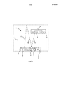
Фиг. 1 изображает систему управления согласно вариантам осуществления;FIG. 1 shows a control system according to embodiments;
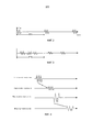
Фиг. 2-7 схематично изображают формы волн (колебательные сигналы) зондовых сигналов согласно вариантам осуществления; иFIG. 2-7 schematically depict waveforms (vibrational signals) of probe signals according to embodiments; and
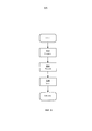
Фиг. 8 является блок-схемой способа согласно вариантам осуществления.FIG. 8 is a flowchart of a method according to embodiments.
ПОДРОБНОЕ ОПИСАНИЕDETAILED DESCRIPTION
Нижеперечисленные варианты осуществления предоставлены посредством примера так, чтобы это раскрытие (описание) было подробным и полным и полностью передавало объем изобретения для специалистов в данной области техники. Аналогичные номера относятся к аналогичным элементам по всему описанию. Упомянутые устройства, раскрытые в нижеперечисленных вариантах осуществления, будут описаны в контексте работы системы.The following embodiments are provided by way of example so that this disclosure (description) will be thorough and complete and fully convey the scope of the invention for those skilled in the art. Similar numbers refer to like elements throughout. Said devices disclosed in the following embodiments will be described in the context of a system operation.
Варианты осуществления настоящего изобретения могут быть применены для усовершенствования локализованного предоставления света в местоположении с фиксированной инфраструктурой датчиков. В этом смысле предоставляются портативные устройства датчика (один из которых ниже упоминается как первый активный датчик), которые предлагают улучшенное обнаружение локального присутствия, и оно является дополнительным компонентом к существующей инфраструктуре.Embodiments of the present invention can be applied to improve the localized provision of light at a location with a fixed sensor infrastructure. In this sense, portable sensor devices are provided (one of which is referred to as the first active sensor below) that offer improved local presence detection and is an additional component to existing infrastructure.
Международная заявка на патент WO2005/069698 описывает носимый детектор пребывания, который основан на использовании уникально модулированного сигнала (например, радиочастотного (RF), инфракрасного (IR) или видимого света, который используется для указания присутствия в некоторых локальных областях так, чтобы некоторые локальные области могли быть освещены должным образом. Это вероятно требует не только использования носимого детектора пребывания, но также и блока приема в контроллере света, который делает возможным различие между потенциально множественными детекторами присутствия, и также идентифицировать их. В частности, в соответствии с WO2005/069698, источник света освещает локальную область светом, который модулируется, чтобы идентифицировать локальную область. В ответ на обнаружение модулированного света носимый детектор пребывания, расположенный в локальной области, излучает сигнал, идентифицирующий локальную область. Таким образом, носимые детекторы являются реактивными, то есть они передают только после приема сигнала от источников света.International patent application WO2005 / 069698 describes a wearable residence detector that uses a uniquely modulated signal (e.g., radio frequency (RF), infrared (IR) or visible light, which is used to indicate presence in some local areas so that some local areas could be properly lit.This probably requires not only the use of a wearable stay detector, but also a reception unit in the light controller, which makes it possible to distinguish between potential about multiple presence detectors, and also to identify them. In particular, in accordance with WO2005 / 069698, the light source illuminates the local area with light that is modulated to identify the local area. In response to the detection of modulated light, a wearable stay detector located in the local area, emits a signal that identifies the local area.Thus, wearable detectors are reactive, that is, they transmit only after receiving a signal from light sources.
В отличие от WO2005/069698 варианты осуществления настоящего изобретения основаны на том, что система уже содержит инфраструктурный ультразвуковой матричный датчик, который выполняет функцию обнаружения присутствия. Согласно настоящему изобретению существует раскрытая портативная система датчика, которая может сосуществовать с датчиком инфраструктуры, таким образом реализуя новые функциональные возможности управления. Портативная система датчика независима от датчика инфраструктуры в том смысле, что она не активизируется или никак иначе не управляется датчиком инфраструктуры, как в случае WO2005/069698.Unlike WO2005 / 069698, embodiments of the present invention are based on the fact that the system already contains an infrastructural ultrasonic array sensor that performs the function of detecting presence. According to the present invention, there is a disclosed portable sensor system that can coexist with an infrastructure sensor, thereby realizing new control functionality. The portable sensor system is independent of the infrastructure sensor in the sense that it is not activated or otherwise controlled by the infrastructure sensor, as in the case of WO2005 / 069698.
Варианты осуществления настоящего изобретения будут раскрыты относительно ультразвуковой модальности датчика, хотя варианты осуществления могут аналогично быть применены к другим активным датчикам, таких как радары. Также предполагается, что ультразвуковой матричный датчик (на который есть ссылка ниже, как на второй активный датчик) фиксируется в инфраструктуре освещения комнаты. Однако, специалисты в области техники понимают, что упомянутый ультразвуковой матричный датчик может быть отделен от инфраструктуры освещения.Embodiments of the present invention will be disclosed regarding the ultrasonic modality of the sensor, although embodiments may similarly be applied to other active sensors, such as radars. It is also assumed that the ultrasonic matrix sensor (referred to below as the second active sensor) is fixed in the room lighting infrastructure. However, those skilled in the art will recognize that said ultrasonic matrix sensor can be separated from the lighting infrastructure.
Фиг. 1 схематично изображает систему 1 управления согласно настоящему изобретению. Система 1 управления согласно схематическому примеру на Фиг. 1 помещена в комнату 10. Типично, комната 10 является комнатой здания. Система 1 управления содержит первый активный датчик 2 и второй активный датчик 3. Первый активный датчик 2 является предпочтительно портативным датчиком. Второй активный датчик 3 является предпочтительно фиксированным датчиком инфраструктуры. Первый активный датчик 2 содержит передатчик 4 и, необязательно, приемник 5. Второй активный датчик 3 содержит передатчик 6, приемник 7 и, необязательно, блок 8 обработки. Система 1 управления может также содержать по меньшей мере один источник 9 света. Согласно вариантам осуществления второй активный датчик 3 и по меньшей мере один из этого по меньшей мере одного источника 9 света является частью одного и того же устройства, например, светильника. Таким образом, источник 9 света, можно сказать, содержит второй активный датчик 3.FIG. 1 schematically depicts a
Передатчик 6 второго активного датчика 3, на этапе S04, скомпонован, чтобы передавать второй зондовый сигнал 11a, как представлено посредством формы волны (колебательного сигнала), изображенной на Фиг. 2, по области, определяемой директивностью передатчика 6. Параметр T определяет длину, по которой форма волны является ненулевой в каждом периоде повторения импульса (PRI) и выбирается согласно требуемому пространственному разрешению. PRI выбирают, чтобы приспособить наибольший ожидаемый диапазон во времени прежде, чем эхо-сигнал 11b переданного второго зондового сигнала 11a, как ожидается, будет принят приемником 7.The
Приемник 7 из второго активного датчика 3 является, предпочтительно, матрицей датчиков приемника и таким образом предпочтительно содержит один или более элементов приемника в матрице. В приемнике 7 принятые сигналы обрабатывают по порядку, чтобы определить информацию восприятия присутствия. Предположим сначала, что эхо-сигнал 11b второго зондового сигнала 11a принят приемником 7, этап S06. Как будет также раскрыто ниже в соответствии с Фиг. 5 и 6, сначала разность сигналов получают посредством взятия разностей эхо-сигналов, соответствующих двум PRI. Статический объект приводит к соответствующему (почти) нулевому компоненту сигнала разности при соответствующем времени прохождения, при этом движущийся объект приводит к ненулевому компоненту сигнала при соответствующем времени прохождения. Мощность в сигнале разности в различных окнах времени прохождения может, таким образом, быть использована посредством второго зондового сигнала 11a и его эхо-сигнала 11b для обнаружения человеческого присутствия в комнате 10. Предположим теперь, что первый активный датчик 2 добавлен в комнату 10. Передатчик 4 первого активного датчика 2 скомпонован, чтобы передавать первый зондовый сигнал 12, этап S02. Предпочтительно первый активный датчик 2 носится пользователем. Когда пользователь первого активного датчика 2 желает локализованное освещение, передатчик 4 первого активного датчика 2 активизируется, например, посредством приема пользовательского ввода от пользователя, для передачи первого зондового сигнала 12. Первый зондовый сигнал 12 принимается приемником 7 второго активного датчика 3, этап S06. Форма волны первого зондового сигнала 12 предпочтительно отличается от формы волны второго зондового сигнала 11a таким образом, что помехи в принимающей матрице датчика между первым зондовым сигналом 11 и вторым зондовым сигналом 12a избегаются, или, по меньшей мере, минимизируются. Это будет также раскрыто ниже со ссылками на Фиг. 5-7.The
Фиг. 3 схематично изображает принятые (эхо-сигналы) зондовые сигналы в конкретном элементе приемника в приемнике 7. Принятые сигналы соответствуют эхо-сигналам 11b двух переданных вторых зондовых сигналов 11a, переданных вторым активным датчиком 3, и одной передаче первого зондового сигнала 12, переданного первым активным датчиком 2. В частности, сплошные и пунктирные формы волн на Фиг. 3 соответствуют эхо-сигналам от движущегося и статического источника, соответственно, и точечная форма волны соответствует принятому первому зондовому сигналу, переданному передатчиком 4 первого активного датчика 2. Таким образом, сигнал, принятый во втором активном датчике 3, и который исходит из первого активного датчика 2, не является эхо-сигналом от первого активного датчика 2, а является прямой передачей от первого активного датчика 2 ко второму активному датчику 3. Следовательно, форма волны первого зондового сигнала 12 от первого активного датчика 3 предпочтительно выбирается, чтобы быть некоррелированной к форме волны второго зондового сигнала 11a (и эхо-сигнала 11b соответственно), переданного вторым активным датчиком 3.FIG. 3 schematically shows the received (echo) probe signals at a particular receiver element in the
Первый зондовый сигнал 12, предпочтительно, содержит только одну пачку форм волны. Первый зондовый сигнал 12 преимущественно содержит только одну пачку форм волны, чтобы избежать исключения первого зондового сигнала 12 во время обработки сигнала в приемнике 7, например, при определении разности между импульсами в двух последовательных PRI. Этот процесс изображен на Фиг. 5. В (i) на Фиг. 5 второй зондовый сигнал (сплошные линии) находится в первом и втором PRI, переданных передатчиком 6 второго активного датчика 3. В (ii) эхо-сигнал второго зондового сигнала находится в первом и втором PRI, принятых приемником 7 второго активного датчика 3 во время τ1 после его передачи. В (iii) первый зондовый сигнал (точечные линии) передается первым активным датчиком 2. В (iv) также первый зондовый сигнал принимается вторым активным датчиком 3 во время τ2 после его передачи. Первый зондовый сигнал 12 принимается в приемнике 7 с произвольной временной задержкой от ее передачи посредством передатчика 4. Таким образом, задержка времени τ2 в большинстве случаев неизвестна в приемнике 7, потому что первый активный датчик 2 и второй активный датчик 3 необязательно синхронизированы. В (v) берется упомянутая разность между полученными сигналами, принятыми в первом и втором PRI, и так как есть только одна версия первого зондового сигнала (где первый зондовый сигнал предпочтительно отличается от второго зондового сигнала), первый зондовый сигнал не затрагивается вычитанием (или по меньшей мере оно не исключается полностью). Вычитание предпочтительно заключается в смещении времени и/или масштабировании сигнала в этих двух PRI.The
Обычно в практических обстоятельствах (например в шумных средах) система управления 1 может быть достаточно устойчивой, если первый активный датчик 2 передает первый зондовый сигнал 12 более 1 раза. Первый зондовый сигнал 12 может быть передан каждое n-е PRI, где n>2. Первый зондовый сигнал 12 предпочтительно не передается в каждом втором PRI, потому что первый зондовый сигнал 12 будет затем исключен, когда будет получена разность в приемнике 7. Таким образом, (передатчик 4) первого активного датчика 2 может быть скомпонован, чтобы передать самое большее один первый зондовый сигнал 12 за каждые три передачи второго зондового сигнала 11a. Предпочтительно первый зондовый сигнал 12 является внутриполосным переданным сигналом относительно приемника 7 второго активного датчика 3. Переданная внутриполосная форма волны (колебательный сигнал) относится к форме волны (колебательному сигналу) с центральной частотой в пределах диапазона частот приемника 7.Usually in practical circumstances (for example, in noisy environments) the
В альтернативном варианте осуществления первый зондовый сигнал 12 является внеполосным сигналом относительно приемника 7 второго активного датчика 3. Такой внеполосный сигнал может, среди прочего, быть передан на акустических частотах или других ультразвуковых частотах в пределах диапазона частот приемника 7. Возможно использовать такой внеполосный сигнал при условии широкополосного частотного отклика элементов приемника второго активного датчика 3. Если принятая мощность превышает заранее определенный порог после корреляции на указанных частотах передачи, то направление прибытия (см. ниже) определяется на основании того, какое определение местоположение достигнута.In an alternative embodiment, the
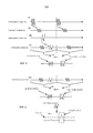
Как отмечено выше, система 1 управления может также содержать блок 8 обработки, который предпочтительно является частью второго активного датчика 3. Блок 8 обработки предпочтительно скомпонован для прогнозной оценки местоположения первого активного датчика 2 на основании принятого первого зондового сигнала 12. Как изображено на Фиг. 6, во втором активном датчике 3 следующая обработка может быть выполнена. В (vi) версия первого зондового сигнала 12 может быть доступной вторым активным датчиком 3. Например, локальная копия формы волны, переданная посредством первого активного датчика 2, поддерживается и коррелируется с принятым сигналом. Если первый активный датчик 2 должен быть уникально определен, то этап предварительной конфигурации может требоваться, где конкретная форма волны ассоциирована с первым активным датчиком 2, и его локальная копия хранится во втором активном датчике 3. Локальная копия предпочтительно является точной копией первого зондового сигнала 12. Если уникальной идентификации первого активного датчика 2 не требуется, то обычная заранее определенная форма волны (предпочтительно все еще отличающаяся от формы волны второго зондового сигнала 11a, который передан вторым активным датчиком 3, но не уникальная относительно различных первых активных датчиков) может быть использована, которая ранее была сохранена (или был доступной) во втором активном датчике 3 (среди прочего посредством программирования или вводом в эксплуатацию). Если дифференциальный сигнал во втором активном датчике 3 коррелирован с локальной копией формы волны от первого активного датчика 2, то в (vii) высокая корреляция может наблюдаться в момент, когда прямой первый зондовый сигнал принят вторым активным датчиком 3. Если корреляция выше, чем порог 'C, тогда может быть определено, что сигнал, равный локальной форме волны, был принят в этот момент времени. Если пик наблюдается из-за корреляции (на Фиг. 6 изображено как «сигнал обнаружен»), то разность фаз сигналов в различных элементах приемника в приемнике 7 может быть использована для определения направления приема (DoA), на основании которого локализуется (определяется его местоположение) первый активный датчик 2 (эквивалентно, пользователь первого активного датчика 2). Стандартный алгоритм DoA может использоваться для оценки DoA. При дальнейшей необязательной обработке DoA может сравниваться с DoA, которое определено (среди прочего, основываясь на отражениях из-за пользователя) первым активным датчиком 2, использующим принятые сигналы во втором активном датчике 3, на основании которого даже может быть определена удаленность пользователя относительно второго активного датчика 3. Компоненты сигнала, за исключением коррелированного компонента сигнала, могут быть использованы для определения присутствия и расширенной информации присутствия, как описано в WO2005/069698. Блок 8 обработки может затем, на основании оцененного местоположения первого активного датчика 2, управлять функцией освещения источника 9 света. Функция освещения предпочтительно относится к освещению местоположения, определенного для первого активного датчика 2.As noted above, the
К настоящему времени предполагалось, что форма волны первого зондового сигнала 12 отличается от формы волны второго зондового сигнала 11a и его эхо-сигнала 11b, который принят приемником 7 второго активного датчика 3. Однако, возможно идентифицировать первый зондовый сигнал 12 также в случае, когда формы волны (колебательные сигналы) первого зондового сигнала 12 и второго зондового сигнала 11a идентичны. Фиг. 7. изображает ситуацию, где форма волны первого зондового сигнала 12 идентична форме волны второго зондового сигнала 11a, но где время прибытия в приемнике 7 отличается. Во втором PRI принимают только один сигнал. Задержка времени для упомянутого одного сигнала во втором PRI равна τ3. Так как только один сигнал принят во втором PRI, можно предположить, что никакая прямая передача не принята во втором PRI. Задержка времени τ3 может затем быть использована для установления порога C. В этом случае порог C будет иметь наклон. Наклон обычно зависит от τ3. Порог C не является, таким образом, фактически фиксированной константой, но пороговой функцией. Пороговая функция C определяется на основании τ3 таким образом, что сигнал в первом PRI соответствует сигналу, принятому во втором PRI при задержке времени τ3, не идентифицированному как прямая передача. Как отмечено на Фиг. 7, два пика имеют одну и ту же высоту, но посредством пороговой функции C только один пик идентифицируется как являющийся представительным для прямой передачи от первого активного датчика 2. Таким образом, прямая передача первого зондового сигнала 12 может быть идентифицирована даже при том, что и форма волны и амплитуда являются теми же самыми, что и у второго зондового сигнала 11a.It has now been assumed that the waveform of the
Альтернативно, если мощность передачи второго зондового сигнала 11a известна, то максимальная полученная мощность любого эхо-сигнала в заданном диапазоне может быть определена. Первый зондовый сигнал 12 первого активного датчика 2 только ослабляется посредством расстояния, а упомянутая мощность является такой же, как после дифференциальной обработки. Можно также предположить, что для заданного диапазона любой сигнал с мощностью выше пороговой инициируется из первого активного датчика. Эта процедура может иметь более высокую скорость необнаружения и может потребовать нескольких ретрансляций от первого активного датчика 3, чтобы гарантировать обнаружение первого зондового сигнала. Кроме того, это может потребовать большей мощности электропередачи передатчика 4 первого активного датчика 3.Alternatively, if the transmit power of the
Согласно вариантам осуществления первый активный датчик 2 также содержит приемник 5. Первый зондовый сигнал 12 затем предпочтительно передается (внутриполосно или внеполосно) только после того, как приемник 5 обнаруживает второй зондовый сигнал 12a, переданный вторым активным датчиком 3. Другими словами, передатчик 4 первого активного датчика 2 может быть скомпонован, чтобы передавать первый зондовый сигнал 11 в ответ на прием второго зондового сигнала 12a приемником 5. Предположим, что продолжительность (времени прохождения) для односторонней передачи (первого и/или второго) зондовых сигналов между первым активным датчиком 2 и вторым активным датчиком равна τ3. Первый зондовый сигнал 12 затем принимается в приемнике 7 при задержке времени приблизительно τ2, которая относится к расстоянию между первым активным датчиком 2 и вторым активным датчиком 3, как изображено на Фиг 4. Местоположение портативного датчика может затем быть получено посредством использования DoA, как определено выше, и посредством времени прохождения сигнала.In embodiments, the first
Согласно вариантам осуществления приемник 5 первого активного датчика 2 является матричным датчиком, который содержит матрицу элементов приемника. Таким образом, когда пользователь первого активного датчика 2 захочет локализованный эффект освещения, первый активный датчик 2 может быть скомпонован, чтобы активизировать свой матричный датчик в режиме прослушивания. Принятые сигналы в матричном датчике, полученные посредством передачи вторых зондовых сигналов 11a от второго активного датчика 3, могут затем быть использованы для определения DoA и определения местоположения первого активного датчика 2 относительно второго активного датчика 3. Эта информация затем может быть сигнализирована назад контроллеру освещения. Подача сигнала может быть осуществлена, используя различные способы воздействия, среди прочего, инфракрасный красный, модулированный свет, испускаемый светодиодами и т.д.According to embodiments, the
Типично зондовые сигналы имеют центральную частоту приблизительно 30-50 кГц, предпочтительно 25-45 кГц, еще более предпочтительно 40 кГц и диапазон частот приблизительно 1-5 кГц, предпочтительно 1-3 кГц, еще более предпочтительно 2 кГц. Как пример, серийно выпускаемые передатчики с центральной частотой 40 кГц имеют диапазон частот 2 кГц.Typically, probe signals have a center frequency of about 30-50 kHz, preferably 25-45 kHz, even more preferably 40 kHz and a frequency range of about 1-5 kHz, preferably 1-3 kHz, even more preferably 2 kHz. As an example, commercially available transmitters with a center frequency of 40 kHz have a frequency range of 2 kHz.
Специалисты в области должны учитывать, что настоящее изобретение ни в коем случае не ограничено предпочтительными вариантами осуществления, описанными выше. Напротив, много модификаций и изменений возможны в рамках приложенной формулы изобретения.Those skilled in the art will appreciate that the present invention is by no means limited to the preferred embodiments described above. On the contrary, many modifications and changes are possible within the scope of the attached claims.
Claims (22)
Applications Claiming Priority (3)
| Application Number | Priority Date | Filing Date | Title |
|---|---|---|---|
| US201261647005P | 2012-05-15 | 2012-05-15 | |
| US61/647,005 | 2012-05-15 | ||
| PCT/IB2013/053802 WO2013171645A2 (en) | 2012-05-15 | 2013-05-10 | Control of lighting devices |
Publications (2)
| Publication Number | Publication Date |
|---|---|
| RU2014150541A RU2014150541A (en) | 2016-07-10 |
| RU2632248C2 true RU2632248C2 (en) | 2017-10-03 |
Family
ID=48782553
Family Applications (1)
| Application Number | Title | Priority Date | Filing Date |
|---|---|---|---|
| RU2014150541A RU2632248C2 (en) | 2012-05-15 | 2013-05-10 | Management of lighting devices |
Country Status (7)
| Country | Link |
|---|---|
| US (1) | US9301374B2 (en) |
| EP (1) | EP2850453B1 (en) |
| JP (1) | JP6207595B2 (en) |
| CN (1) | CN104303076B (en) |
| ES (1) | ES2753074T3 (en) |
| RU (1) | RU2632248C2 (en) |
| WO (1) | WO2013171645A2 (en) |
Families Citing this family (1)
| Publication number | Priority date | Publication date | Assignee | Title |
|---|---|---|---|---|
| US10955550B1 (en) * | 2019-12-09 | 2021-03-23 | Tymphany Acoustic Technology (Huizhou) Co., Ltd. | Synchronization of motion-sensitive acoustic speakers |
Citations (5)
| Publication number | Priority date | Publication date | Assignee | Title |
|---|---|---|---|---|
| EP0681413A2 (en) * | 1994-05-06 | 1995-11-08 | Koninklijke Philips Electronics N.V. | Occupancy sensing device and system for controlling a lamp comprising such a device |
| JPH09287913A (en) * | 1996-04-19 | 1997-11-04 | Matsushita Electric Ind Co Ltd | Apparatus for detecting position of object, method for detecting human body |
| US20040141633A1 (en) * | 2003-01-21 | 2004-07-22 | Minolta Co., Ltd. | Intruding object detection device using background difference method |
| WO2005069698A1 (en) * | 2004-01-12 | 2005-07-28 | Koninklijke Philips Electronics, N.V. | Lighting control with occupancy detection |
| WO2011151772A1 (en) * | 2010-06-03 | 2011-12-08 | Koninklijke Philips Electronics N.V. | Configuration unit and method for configuring a presence detection sensor |
Family Cites Families (19)
| Publication number | Priority date | Publication date | Assignee | Title |
|---|---|---|---|---|
| US3799676A (en) * | 1972-05-26 | 1974-03-26 | Us Air Force | Optical tracking system |
| US5504477A (en) | 1993-11-15 | 1996-04-02 | Wybron, Inc. | Tracking system |
| US5640143A (en) | 1995-02-06 | 1997-06-17 | Mytech Corporation | Occupancy sensor and method of operating same |
| US5905442A (en) * | 1996-02-07 | 1999-05-18 | Lutron Electronics Co., Inc. | Method and apparatus for controlling and determining the status of electrical devices from remote locations |
| US6791458B2 (en) * | 2001-05-22 | 2004-09-14 | Hubbell Incorporated | Dual technology occupancy sensor and method for using the same |
| EP1496371A1 (en) * | 2003-07-07 | 2005-01-12 | Mitsubishi Electric Information Technology Centre Europe B.V. | Generation of packets of waveforms |
| JP5091114B2 (en) * | 2005-04-22 | 2012-12-05 | コーニンクレッカ フィリップス エレクトロニクス エヌ ヴィ | Lighting control |
| EP1966625A1 (en) * | 2005-12-19 | 2008-09-10 | Koninklijke Philips Electronics N.V. | Method and apparatus for lighting control |
| CN101093610A (en) * | 2006-06-19 | 2007-12-26 | 上海国皓电子有限公司 | Radio controlled acoustic, optic and electric recreation apparatus |
| US7943908B2 (en) * | 2007-01-22 | 2011-05-17 | University Of Maryland | Sensor system with surface-plasmon-polariton (SPP) enhanced selective fluorescence excitation and method |
| JP2009098098A (en) * | 2007-10-19 | 2009-05-07 | Yamaguchi Univ | Human body detecting system by ultrasonic radar |
| CN101861761B (en) | 2007-11-16 | 2014-12-17 | 皇家飞利浦电子股份有限公司 | Direction controllable lighting unit with ultrasound |
| JP5466995B2 (en) | 2010-05-24 | 2014-04-09 | パナソニック株式会社 | Remote control system for lighting |
| ES2614878T3 (en) * | 2010-06-01 | 2017-06-02 | Geistlich Pharma Ag | Methods and compositions for oral pharmaceutical therapy |
| WO2011151796A1 (en) | 2010-06-03 | 2011-12-08 | Koninklijke Philips Electronics N.V. | System and method for lighting control |
| US8174931B2 (en) * | 2010-10-08 | 2012-05-08 | HJ Laboratories, LLC | Apparatus and method for providing indoor location, position, or tracking of a mobile computer using building information |
| CN104205182B (en) * | 2012-03-20 | 2018-03-09 | 飞利浦灯具控股公司 | The control of lighting apparatus |
| US8922788B2 (en) * | 2012-12-22 | 2014-12-30 | Covidien Lp | Methods and systems for determining a probe-off condition in a medical device |
| WO2015109277A1 (en) * | 2014-01-17 | 2015-07-23 | Gojo Industries, Inc. | Sensor configuration |
-
2013
- 2013-05-10 RU RU2014150541A patent/RU2632248C2/en active
- 2013-05-10 WO PCT/IB2013/053802 patent/WO2013171645A2/en active Application Filing
- 2013-05-10 CN CN201380025287.7A patent/CN104303076B/en active Active
- 2013-05-10 US US14/394,879 patent/US9301374B2/en active Active
- 2013-05-10 EP EP13735415.5A patent/EP2850453B1/en active Active
- 2013-05-10 ES ES13735415T patent/ES2753074T3/en active Active
- 2013-05-10 JP JP2015512174A patent/JP6207595B2/en active Active
Patent Citations (5)
| Publication number | Priority date | Publication date | Assignee | Title |
|---|---|---|---|---|
| EP0681413A2 (en) * | 1994-05-06 | 1995-11-08 | Koninklijke Philips Electronics N.V. | Occupancy sensing device and system for controlling a lamp comprising such a device |
| JPH09287913A (en) * | 1996-04-19 | 1997-11-04 | Matsushita Electric Ind Co Ltd | Apparatus for detecting position of object, method for detecting human body |
| US20040141633A1 (en) * | 2003-01-21 | 2004-07-22 | Minolta Co., Ltd. | Intruding object detection device using background difference method |
| WO2005069698A1 (en) * | 2004-01-12 | 2005-07-28 | Koninklijke Philips Electronics, N.V. | Lighting control with occupancy detection |
| WO2011151772A1 (en) * | 2010-06-03 | 2011-12-08 | Koninklijke Philips Electronics N.V. | Configuration unit and method for configuring a presence detection sensor |
Also Published As
| Publication number | Publication date |
|---|---|
| EP2850453A2 (en) | 2015-03-25 |
| US20150123561A1 (en) | 2015-05-07 |
| US9301374B2 (en) | 2016-03-29 |
| EP2850453B1 (en) | 2019-09-25 |
| JP6207595B2 (en) | 2017-10-04 |
| WO2013171645A2 (en) | 2013-11-21 |
| CN104303076B (en) | 2017-11-21 |
| WO2013171645A3 (en) | 2014-01-23 |
| ES2753074T3 (en) | 2020-04-07 |
| CN104303076A (en) | 2015-01-21 |
| RU2014150541A (en) | 2016-07-10 |
| JP2015524143A (en) | 2015-08-20 |
Similar Documents
| Publication | Publication Date | Title |
|---|---|---|
| JP6198809B2 (en) | Interference detection in active sensor networks | |
| US10444334B2 (en) | Controlling transmission of pulses from a sensor | |
| US10126406B2 (en) | Method and apparatus for performing ultrasonic presence detection | |
| JP6373845B2 (en) | Presence detector and method of operation of presence detector | |
| AU2008240366B2 (en) | Mobile object position determination | |
| US9857458B2 (en) | Controlling transmission of pulses from a sensor | |
| RU2653357C2 (en) | Mitigating disturbance in sensing | |
| RU2632248C2 (en) | Management of lighting devices | |
| KR20100035915A (en) | Uwb radar sensor and operation synchronization method between the uwb radar sensors with overlap area | |
| JP2015524143A5 (en) | ||
| WO2013108229A2 (en) | Robust presence detection through audible components analysis | |
| JP6731621B2 (en) | Equipment control device, equipment control system, and equipment control program |
Legal Events
| Date | Code | Title | Description |
|---|---|---|---|
| HZ9A | Changing address for correspondence with an applicant |